

LG AB-W3067SA3, AB-W3667SA3 Installation Manual

P/NO : MFL62541003
www.lg.com
INSTALLATION MANUAL
AIR CONDITIONER
• Please read this installation manual completely before installing the product.
• Installation work must be performed in accordance with the national wiring
standards by authorized personnel only.
• Please retain this installation manual for future reference after reading it
thoroughly.
TYPE : CEILING CONCEALED DUCT
Model : AB-W3067SA3 / AB-W3667SA3
ENGLISH

• Do not cool excessively indoors. This may be harmful for your health and may consume more
electricity.
• Block sunlight with blinds or curtains while you are operating the air conditioner.
• Keep doors or windows closed tightly while you are operating the air conditioner.
• Adjust the direction of the air flow vertically or horizontally to circulate indoor air.
• Speed up the fan to cool or warm indoor air quickly, in a short period of time.
• Open windows regularly for ventilation as the indoor air quality may deteriorate if the air conditioner is used for many hours.
• Clean the air filter once every 2 weeks. Dust and impurities collected in the air filter may block the
air flow or weaken the cooling / dehumidifying functions.
For your records
Staple your receipt to this page in case you need it to prove the date of purchase or for warranty
purposes. Write the model number and the serial number here:
Model number :
Serial number :
You can find them on a label on the side of each unit.
Dealer’s name :
Date of purchase :
Here are some tips that will help you minimize the power consumption when you use the air
conditioner. You can use your air conditioner more efficiently by referring to the instructions
below:
TIPS FOR SAVING ENERGY
ENGLISH
TIPS FOR SAVING ENERGY
2
3
IMPORTANT SAFETY INSTRUCTIONS
READ ALL INSTRUCTIONS BEFORE USING THE APPLIANCE.
Always comply with the following precautions to avoid dangerous situations and ensure peak
performance of your product
WARNING
It can result in serious injury or death when the directions are ignored
CAUTION
It can result in minor injury or product damage when the directions are ignored
WARNING
• Installation or repairs made by unqualified persons can result in hazards to you and others.
• Installation MUST conform with local building codes or, in the absence of local codes, with
the Nation Electrical Code NFPA 70/ANSI C1-1003 or current edition and Canadian Electrical
Code Part1 CSA C.22.1.
• The information contained in the manual is intended for use by a qualified service technician
familiar with safety procedures and equipped with the proper tools and test instruments.
• Failure to carefully read and follow all instructions in this manual can result in equipment malfunction, property damage, personal injury and/or death.
Installation
• Do not use a defective or underrated circuit breaker. Use this appliance on a dedicated circuit.
- There is risk of fire or electric shock.
• For electrical work, contact the dealer, seller, a qualified electrician, or an Authorized Service Center.
- Do not disassemble or repair the product. There is risk of fire or electric shock.
• Always ground the product.
- There is risk of fire or electric shock.
• Install the panel and the cover of control box securely.
- There is risk of fire or electric shock.
• Always install a dedicated circuit and breaker.
- Improper wiring or installation may cause fire or electric shock.
• Use the correctly rated breaker or fuse.
- There is risk of fire or electric shock.
• Do not modify or extend the power cable.
- There is risk of fire or electric shock.
• Do not let the air conditioner run for a long time when the humidity is very high and a door or a window is left open.
- Moisture may condense and wet or damage furniture.
• Be cautious when unpacking and installing the product.
- Sharp edges could cause injury. Be especially careful of the case edges and the fins on the con-
denser and evaporator.
• For installation, always contact the dealer or an Authorized Service Center.
- There is risk of fire, electric shock, explosion, or injury.
!
!
!
ENGLISH
IMPORTANT SAFETY INSTRUCTIONS

• Do not install the product on a defective installation stand.
- It may cause injury, accident, or damage to the product.
• Be sure the installation area does not deteriorate with age.
- If the base collapses, the air conditioner could fall with it, causing property damage, product failure,
and personal injury.
Operation
• Do not store or use flammable gas or combustibles near the product.
- There is risk of fire or failure of product.
CAUTION
Installation
• Always check for gas (refrigerant) leakage after installation or repair of product.
- Low refrigerant levels may cause failure of product.
• Install the drain hose to ensure that water is drained away properly.
- A bad connection may cause water leakage.
• Keep level even when installing the product.
- To avoid vibration or water leakage.
• Do not install the product where the noise or hot air from the outdoor unit could damage the neighborhoods.
- It may cause a problem for your neighbors.
• Use two or more people to lift and transport the product.
- Avoid personal injury.
• Do not install the product where it will be exposed to sea wind (salt spray) directly.
- It may cause corrosion on the product. Corrosion, particularly on the condenser and evaporator
fins, could cause product malfunction or inefficient operation.
!
ENGLISH
IMPORTANT SAFETY INSTRUCTIONS
4
5
2
TIPS FOR SAVING ENERGY
3
IMPORTANT SAFETY
INSTRUCTIONS
6
INTRODUCTION
6
Features
7
INSTALLATION PLACES
7
Indoor unit
7
Outdoor unit
8
THE INDOOR UNIT
INSTALLATION
8
Indoor unit installation
11
Insulation, others
11
Checking the Drainage
12
PIPING LENGTH AND THE
ELEVATION
13
CONNECTING PIPES
13
Preparation of Piping
14
Connecting the pipings to the indoor unit
and drain hose to drain pipe
14
Connecting the pipes to the Outdoor unit
15
LEAKAGE TEST AND
EVACUATION
15
Preparation
15
Leakage test
16
Evacuation
17
WIRING CONNECTION
17
Electrical Wiring
18
Connecting cables to the Indoor Unit
18
Clamping of cables
19
Connecting the cable to the Outdoor Unit
20
FORMING THE PIPING
21
REMOTE CONTROLLER
INSTALLATION
21
Point of remote controller installation
22
Wired remote controller installation
23
EXTERNAL STATIC PRESSURE & FLOW
24
TEST RUNNING
24
Precaution in test running
24
Check the following tiems when installation
is complete
24
Connection of power supply
24
Evaluation of the performance
26
SELF-DIAGNOSIS FUNCTION
26
Indoor Unit Error
27
Outdoor Unit Error
28
DIP SWITCH SETTING
29
ACCESSORY INSTALLATION GUIDE
29
Dry Contact(Only AC 24V)
30
PI485
31
RF Remote Controller
32
Damper Controller
33
Remote Temperature Sensor
34
Two wired remote controller
35
Simple Contact
36
INSTALLATION GUIDE AT
THE SEASIDE
TABLE OF CONTENTS
ENGLISH
TABLE OF CONTENTS
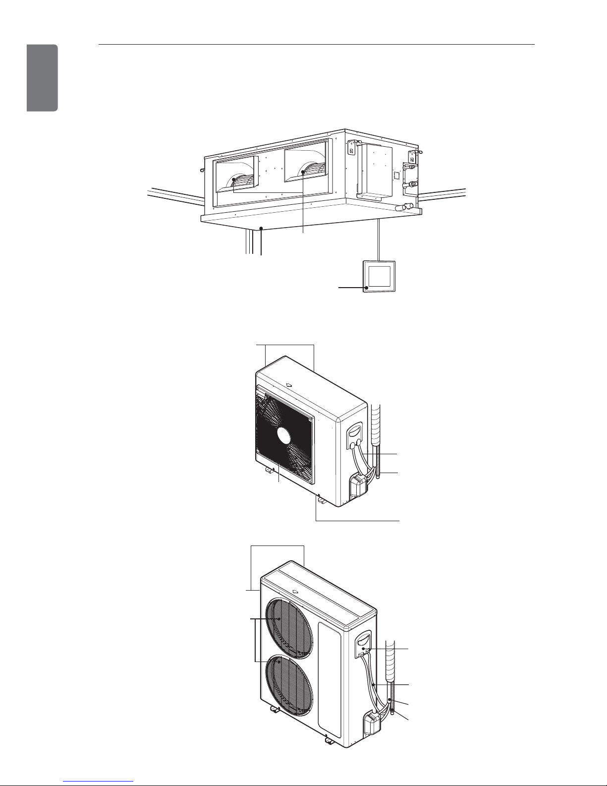
Remote Controller
Air intake vents
Air outlet vents
Air outlet vents
(Side)
(Rear)
Air intake vents
Piping
Drain hose
Connecting
wire
Control
cover
Air Intake
Vents Side
Base Plate
Air Outlet Vents
Connecting
Wires
Drain Hose
Rear
6
INTRODUCTION
ENGLISH
Features
INTRODUCTION
INSTALLATION PLACES
ENGLISH
7
Indoor unit
- The place shall easily bear a load exceeding
four times the indoor unit’s weight.
- The place shall be able to inspect the unit as
the figure.
- The place where the unit shall be leveled.
- The place shall allow easy water drainage.
- The place shall easily connect with the outdoor unit.
- The place where the unit is not affected by
an electrical noise.
- The place where air circulation in the room
will be good .
- There should not be any heat source or
steam near the unit
* Suitable dimension “H” is necessary to get
a slope to drain as figure.
Outdoor unit
- If an awning is built over the unit to prevent
direct sunlight or rain exposure, make sure
that heat radiation from the condenser is not
restricted.
- Ensure that the spaces indicated by arrows
around front, back and side of the unit.
- Do not place animals and plants in the path
of the warm air.
- Take the air conditioner weight into account
and select a place where noise and vibration
are minimum.
- Select a place so that the warm air and noise
from the air conditioner do not disturb neighbors.
H=200 or more
Top view
(unit: mm)
Front view
(unit: mm)
Front
Inspection hole
(600 x 600)
Control box
1000
More than
300
More than 700
More than 600
More thanMore than
300300
Sunroof
Fence or
obstacles
OUTDOOROUTDOOR
U
n
i
t
U
n
i
t
OUTDOOR
Unit
More than
300
Unit : mm
INSTALLATION PLACES
8
ENGLISH
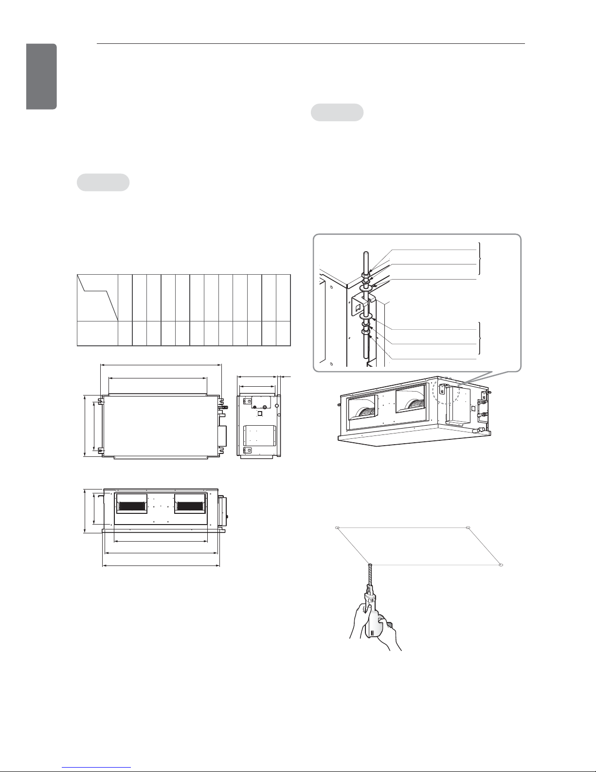
THE INDOOR UNIT INSTALLATION
THE INDOOR UNIT INSTALLATION
Indoor unit installation
• Installation of Unit
Install the unit above the ceiling correctly.
Case1
Position of suspension Bolt
- Apply a joint-canvas between the unit and
duct to absorb unnecessary vibration.
- Apply a filter Accessory at air return hole.
Case2
Position of Console Bolt
- A place where the unit will be leveled and
that can support the weight of the unit.
- A place where the unit can withstand its
vibration.
- A place where service can be easily performed.
- Select and mark the position for fixing bolts.
- Drill the hole for set anchor on the face of
ceiling.
Dimension
Capacity
(Btu/h)
A B C D E F G H I J K L
30/36k
1352 1320 840 287 400 441 563 1172 1365 317 360 40
I
H
C
B
A
FDEG
J
KL
M10 Nut X 4
M10 SP. washer
X 4
M10 washer
X 4
(Local
supply)
M10 washer X 4
M10 SP. washer X 4
M10 Nut
X 4
(Local
supply)
(Unit:mm)

THE INDOOR UNIT INSTALLATION
ENGLISH
- Insert the set anchor and washer onto the suspension bolts for locking the suspension bolts on
the ceiling.
- Mount the suspension bolts to the set anchor firmly.
- Secure the installation plates onto the suspension bolts (adjust level roughly) using nuts, washers and spring washers.
• Local supply
① Set anchor
② Plate washer - M10
③ Spring washer - M10
④ Nut - W3/8 or M10
⑤ Suspension bolt - W3/8 or M10
9
1 Set anchor
Old building New building
2 Plate washer
3 Spring washer
4 Nut
5 Suspension
bolts
Tighten the nut and bolt to prevent unit falling.
CAUTION
!
1 Install declination of the indoor unit is very important for the drain of the duct type air con-
ditioner.
2 Minimum thickness of the insulation for the connecting pipe shall be 10mm.
* The unit must be declined to the drain hose connected when finished installation.
CAUTION
!
Ceiling
1~3mm
Drainage hole
Drainage hole
Safety drain hole Main drain hole
CORRECT INCORRECT
10
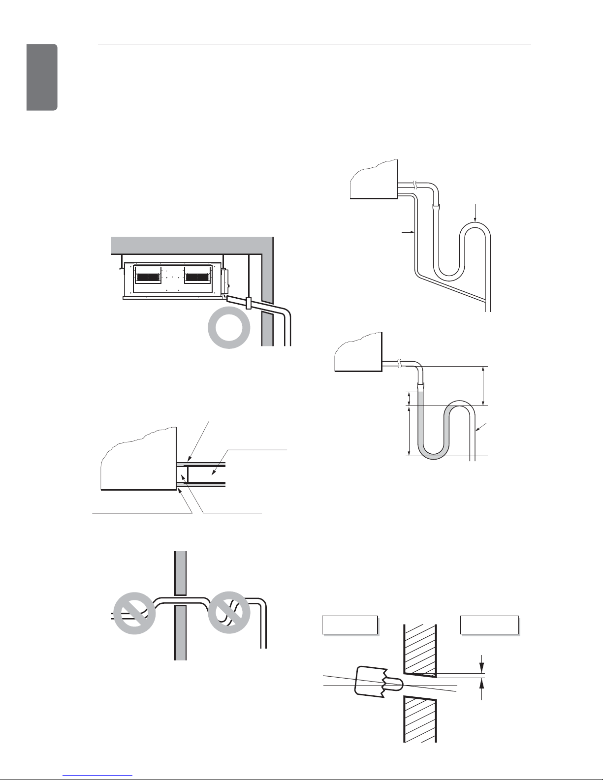
THE INDOOR UNIT INSTALLATION
ENGLISH
Caution for gradient of unit and
drain piping
Lay the drain hose with a downward inclination so water will drain out.
Main drain
- Always lay the drain with downward inclination (1/50 to 1/100).
Prevent any upward flow or reverse flow in
any part.
- 10mm or thicker formed thermal insulator
shall always be provided for the drain pipe.
- Install the P-Trap (or U-Trap) to prevent a
water leakage caused by the blocking of
intake air filter.
- Upward routing not allowed
Safety drain
- There is no need to provide a trap for the
safty drain. If the safty drain pipe is connected to the main drain pipe, make the connection below the trap on the main drain pipe.
- Drill the piping hole with 70mm dia, hole
core drill.
- Piping hole should be slightly slant to the
outdoor side.
CORRECT
U-Trap
B
C
A 70mm
B 2C
C 2 x SP
SP = External
Pressure
(mmAq)
Ex) External Pressure = 10mmAq
A 70mm
B 40mm
C 20mm
A
Safety drain pipe
Main drain pipe
Drainage hole
Make sure to be closed.
Unit
Drainage pipe
(Local supply)
Thermal insulator
(Local supply)
Applied U-Trap Dimension
5~7mm
Indoor Outdoor
WALL
THE INDOOR UNIT INSTALLATION
ENGLISH
Insulation, others
Insulate the joint and tubes completely.
Thermal insulation : All thermal insulation
must comply with local requirement.
Indoor unit
Refrigerant pipe
- Insulate and tape the gas piping.
Test and check
* After all workings are finished, check the
working and operation.
- Air distribution : Is the air circulation good?
- Drain : Is the drainage smoothly and no
sweating?
- Gas leakage : Is the piping connection correctly?
- Wiring : Is the wiring connection correctly?
- Lock-bolt : Is the lock-bolt of compressor
loosened?
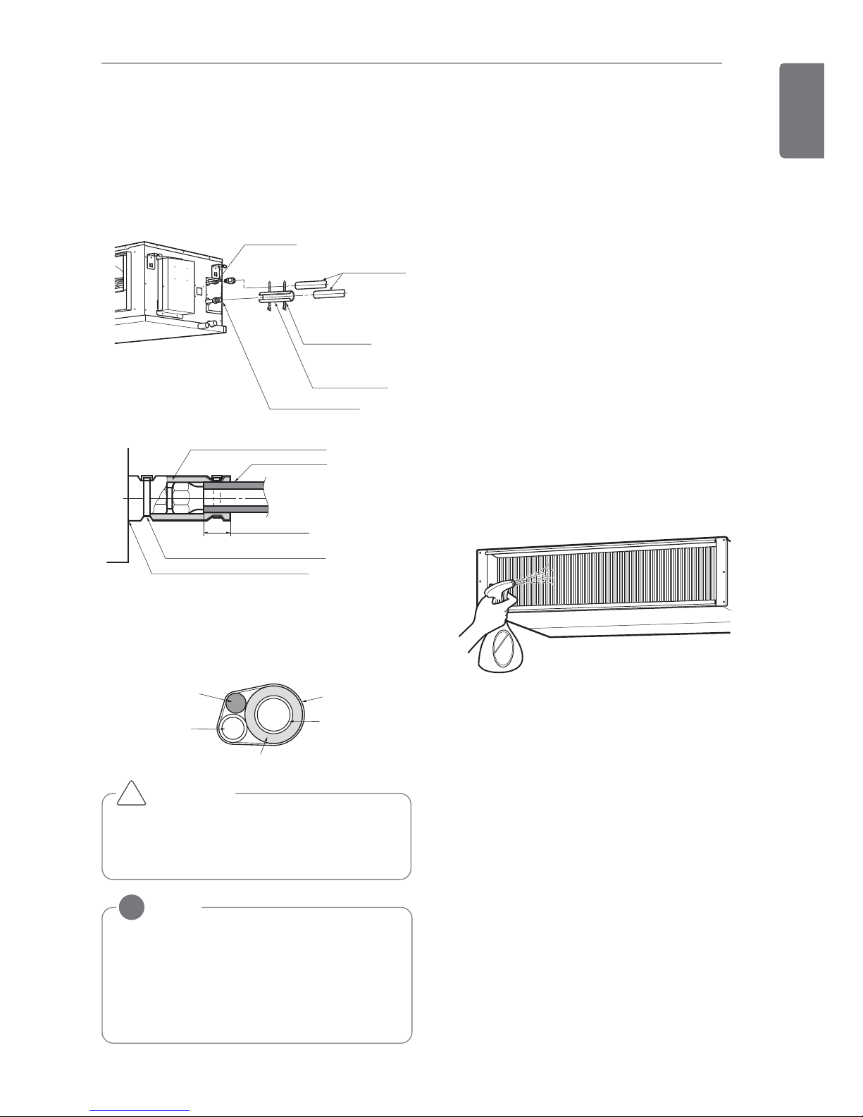
Checking the Drainage
Checking the Drainage
* Check the drainage.
- Spray one or two glasses of water upon the
evaporator.
- Ensure that water flows drain hose of indoor
unit without any leakage.
11
Make sure that there is no clearance here.
Overlap with thermal
insulator for piping.
Thermal insulator for refrigerant pipe
(Local supply)
Thermal insulator for
piping(Local supply)
Hose crip for thermal insulator(Local supply)
Union for
liquid pipe
Refrigerant pipe
and thermal
insulator
(Local supply)
Union for gas pipe
Thermal insulator
for refrigerant pipe
(Local supply)
Hose crip for
thermal insulator
(Local supply)
Power cable
Thermal insulator
Gas pipe
Liquid pipe
Tape
Cutting line of insulation must look upper
direction. Thickness of insulation is
10mm or over.
CAUTION
!
NOTE
!
Recommended Insulation material
Meterial : FOAM PE
Thickness : 10mm
Density : less than 0.032 ±0.005(g/cm2)
Thermal conductivity : less than
0.03(kcal/m.hr.°C)
12
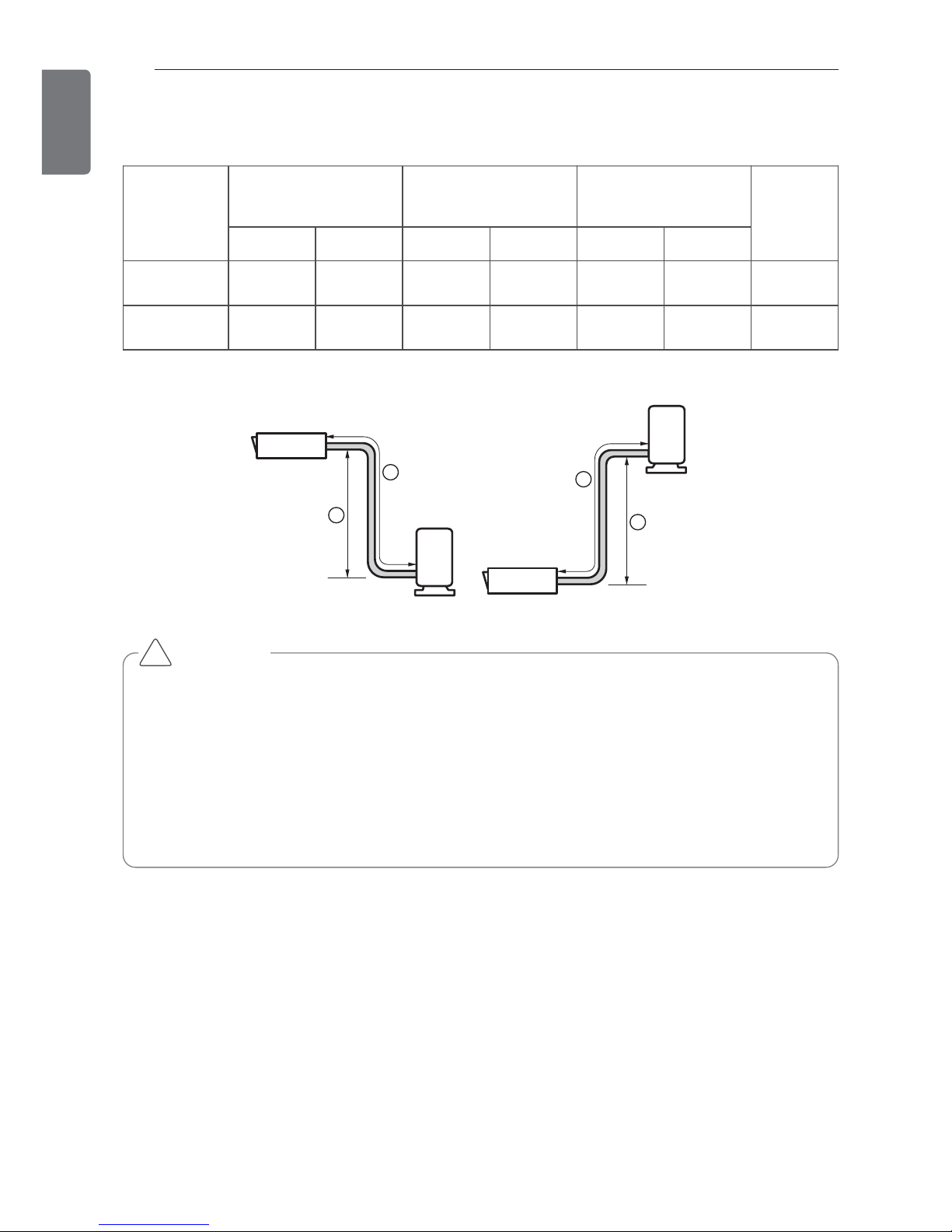
PIPING LENGTH AND THE ELEVATION
ENGLISH
PIPING LENGTH AND THE ELEVATION
Capacity
(Btu/h)
Pipe Size
mm(inch)
Length A(m) Elevation B(m)
*Additional
refriger-
ant(g/m)
Gas Liquid Standard Max. Standard Max.
30 k 15.88(5/8) 9.52(3/8) 7.5 50 0 30 40
36 k 15.88(5/8) 9.52(3/8) 7.5 50 0 30 50
Outdoor unit
Indoor unit
A
B
Outdoor uni
t
Indoor unit
A
B
• The standard pipe length is 7.5 m and no need to additional charge of the refrigerant to
max 15 m. If the pipe length exceeds 15 m, need to additional charge of the refrigerant
which according to the table.
• If 36 kBtu/h model is installed at a distance of 50m, 1,750g of refrigerant should be added
(50-15) x 50g = 1,750g
• Capacity is based on standard length and maximun allowance length is on the basis of reliability.
• Improper refrigerant charge may result in abnormal cycle.
CAUTION
!
 Loading...