

Page 1
- 52 -
Electronic Parts Troubleshooting Guide
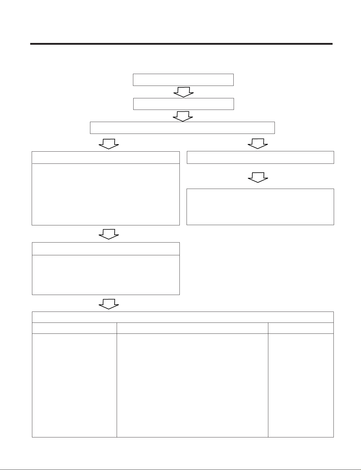
1. Product does not operate at all.
(* Refer to Electronic Control Device drawing and Schematic diagram.)
Turn off Main Power
Turn on Main Power
Does "beeping" sound is made from the Indoor Unit?
Primarily, the operating condition of Micom is OK.
Check the voltage of power(About AC 220V/AC240V, 50Hz)
• Main power's voltage
• Voltage applied to the unit
• Connecting method of Indoor/Outdoor connecting
cable
• Check PWB Ass'y
- Fuse
- Pattern damage
- Varistor(ZNR01J)
Check the connection housing for contacting
• Connector related to CN-TAB1, RY-COMP No. 3 PIN
• Connector related to CN-MOTOR
• Connector contacting of Outdoor Fan/Compressor
• Display PWB Ass'y Check
Check each load(Indoor/Outdoor Fan Motor,
Compressor, Stepping Motor) and contacting
condition of related connector
PCB Board Operation Check
Items
• Power Transformer
(Outdoor unit)
- Input Voltage
- Output Voltage
‹X
• IC01D(7812) Output
(Indoor/Outdoor unit)
‹X
• IC02D(7805) Output
(Indoor/Outdoor unit)
‹X
• IC01A(KIA7036, Reset IC)
X01(8MHz)
• Replace Trans
• Replace IC01D
• Replace IC02D
• Replace faulty parts
- About AC220V/240V±10% - Check the power voltage
- About AC14±3V
• DC +12V
• DC +5V
• Voltage of Micom 10,
(DC +4.5V over) and Soldering condition.
Content Remedy
NO
YES
(After 10 seconds)
Page 2
- 53 -
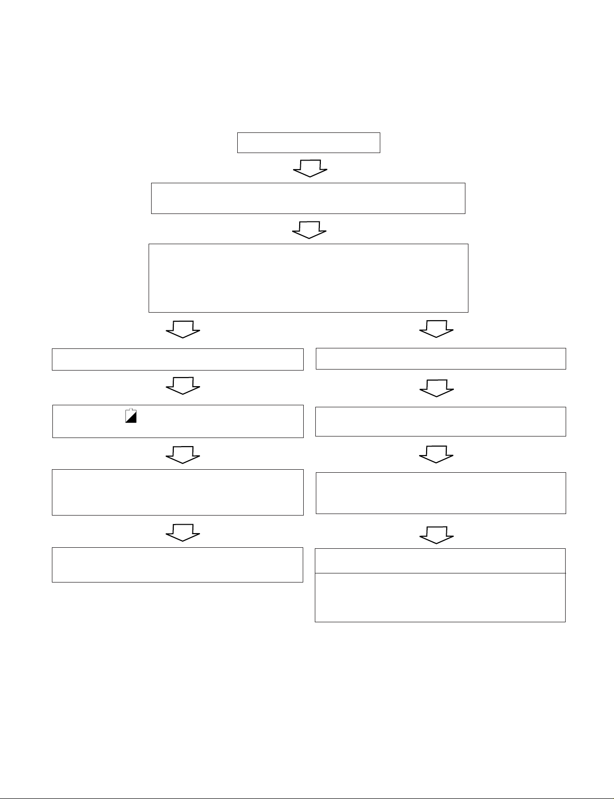
2. The product is not operate with the remote controller.
Turn on Main Power
While the compressor has been stopped, the compressor does not
operate owing to the delaying function for 3 minutes after stopped.
Caused by other parts except the remote controller
Cause by the remote controller
When the mark( ) is displayed in LCD screen, replace
battery.
Check the contact of CN-DISPI connector.
When the compressor stopped Indoor Fan is driven by a low speed.
At this point the wind speed is not controlled by the remote controller.
(When operated in the Sleeping Mode, the wind speed is set to the
low speed by force.)
Check DISP PWB Ass'y
- Voltage between CN DISP1 ¤ - ¤ : DC +5V
When the detect switch(double key) inside the remote
controller door is fault, it is impossible to operate
temperature regulating(¡ª/¡ ) and wind speed selecting.
Check the connecting circuit between the remote controller
MICOM (No. § ) - R17(2Ω) - IR LED - Q1 - R16(2.2KΩ).
Check point
• Check the connecting circuit between PIN §łR02L 5100 Ω - Cø1L(680PF) - MICOM PIN No. 43
• Check Receiver Ass'y
Page 3

- 54 -
3. Compressor/Outdoor Fan are unable to drive.
Turn on Main Power
Operate "Cooling Mode( )" by setting the desired temperature of the
remote controller is less than one of the indoor temperature by 1°C at least.
When in Air Circulation Mode, Compressor/Outdoor Fan is stopped.
Check the sensor for indoor temperature is attached as close as to be
effected by the temperature of Heat Exchanger(EVA).
When the sensor circuit for indoor temperature and connector are in bad
connection or are not engaged, Compressor/Outdoor Fan is stopped.
• Check the related circuit of R02H(12.1K), R04H(6.2K), Micom (No.26, 27)
(Indoor unit).
• Check the indoor temperature sensor is disconnected or not(About 10k Ω/ at 25°C).
Turn off Main Power
• Check the electrical wiring diagram of outdoor side.
• Check the abnormal condition for the component of
Compressor/Outdoor Fan Motor.
• Check the "open" or "short" of conmecting wires between indoor and
outdoor.
Check Relay(RY - COMP) for driving compressor.
• When the power(About AC220V/240V) is applied to the connecting wire
terminal support transferred to compressor, PWB Ass'y is normal.
• Check the circuit related to the relay.
Check point COMP ON COMP OFF
Between Micom(No.
DC5V DC0V
59) and GND
Between IC01M(No. 15) Below DC 1V
About DC12V
and GND (app)
Page 4

- 55 -
Check the TRIAC high speed operation by Remocon.
(The Indoor Fan Motor is connected)
Turn off Main power
Check the connection of CN-MOTOR
Check the Fan Motor
Check the Fuse(AC250V/T2A)
Turn ON Main Power
Check the related circuit of indoor Fan Motor.
• The pin NO 63 of Micom, and the part for driving TRIAC(the input and
output signal of IC01M, PIN NO 1, 16)
• Check the pattern
• Check the TRIAC
- TRIAC Open: Indoor Fan Motor never operate
- TRIAC short: Indoor Fan Motor always operates in case of ON or OFF.
4. When indoor Fan does not operate.
The voltage of PIN NO 1(blue) and 3(yellow) of CN-MOTOR.
About AC 180V over About AC 50V over
TRIAC is not damaged TRIAC Check
Page 5

- 56 -
6. When Heating does not operate
Operate “Heating Mode( )” by setting the desired temperature of the
remote controller is higher than one of the indoor temperature by 2°C
at least.
In heating Mode, the indoor fan operates in case the pipe temperature
is higher than 28°C.
Turn ON Main Power
• Confirm that the Vertical Louver is normally geared with the shaft of
Stepping Motor.
• If the regular torque is detected when rotating the Vertical Louver with
hands ¢¡ Normal
• Check the connecting condition of CN-U/D Connector
• Check the soldering condition(on PWB) of CN-U/D Connector
If there are no problems after above checks
• Confirm the assembly conditions that are catching and interfering parts
in the rotation radial of the Vertical Louver
5. When Vertical Louver does not operate.
Check the operating circuit of the Vertical Louver
• Confirm that there is DC +12V between pin¤ (RED) of CN-U/D and
GND.
• Confirm that there is a soldering short at following terminals.
- Between , , and of MICOM
- Between , , and of IC01M
- Between , , and of IC01M
60 61 62 63
3 4 5 6
11 12 13 14
Page 6

- 57 -
Check the connector of intake and pipe sensor(thermistors)
• Check the related circuit of R02H(12.1K), R04H(6.2K),
Micom(No. 26, 27).
• Check the indoor room temperature is disconnected or not (about
10KΩ/at 25°C).
• Check the indoor pipe temperature is disconnected or not (about
5KΩ/at 25°C).
Check the DC voltage on the PWB ASS’Y
• The details of check are as followings
Check point
Between Micom
(NO.59) and GND
Between IC01M
(NO.15) and GND
Comp ON
DC 5V
Below DC 1V
Comp OFF
DC 0V
About DC
12V
Check point
Between Micom
(No. 51) and GND
Between IC02M
(No. 15) and GND
4 way ON
DC 5V
Below DC 1V
4 way OFF
DC 0V
About DC 12V
Check point
Between Micom
(NO.53) and GND
Between IC02M
(No. 14) and GND
Fan ON
DC 5V
Below DC 1V
Fan OFF
DC 0V
About DC 12V
• Comp Relay.
• 4 way Relay
• Outdoor fan Relay
Turn off Main Power
• Check the electrical wiring diagram of outdoor side.
• Check the abnormal condition for the component of
Compressor/Outdoor Fan Motor, 4 way.
• Check the "open" or "short" of connecting wires between indoor and
outdoor.
 Loading...