

Page 1
- 38 -
Disassembly of the parts (Indoor unit)
Warning :
Disconnect the unit from power supply before making
any checks.
Be sure the power switch is set to “OFF”.
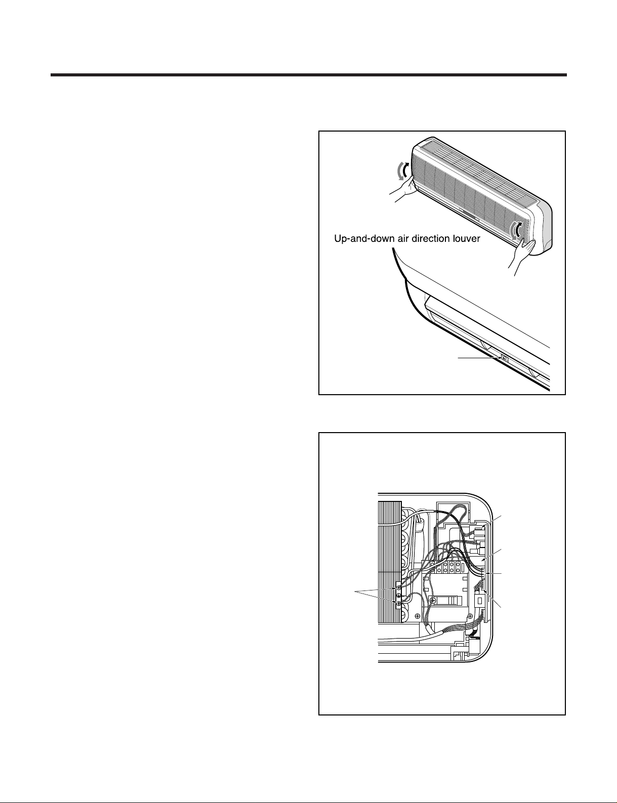
To remove the Grille from the Chassis.
• Set the up-and-down air discharge louver to open
position (horizontally) by finger pressure.
• Remove the securing screws
• To remove the Grille, pull the lower left and right
side of the grille toward you (slightly tilted) and lift it
straight upward.
1. To remove the sensor, housing connect, earth
conductor & step motor conductor with sensor
holder, Motor, Evaporator & P.C.B.
Screw
(3EA)
Power
Conductor
Step Motor
Conductor
Earth
Conductor
Motor
Conductor
Sensor
Conductor
■ LS-K1823/1863/1867/2465/2665/2669CL/CM/CN
Page 2
- 39 -
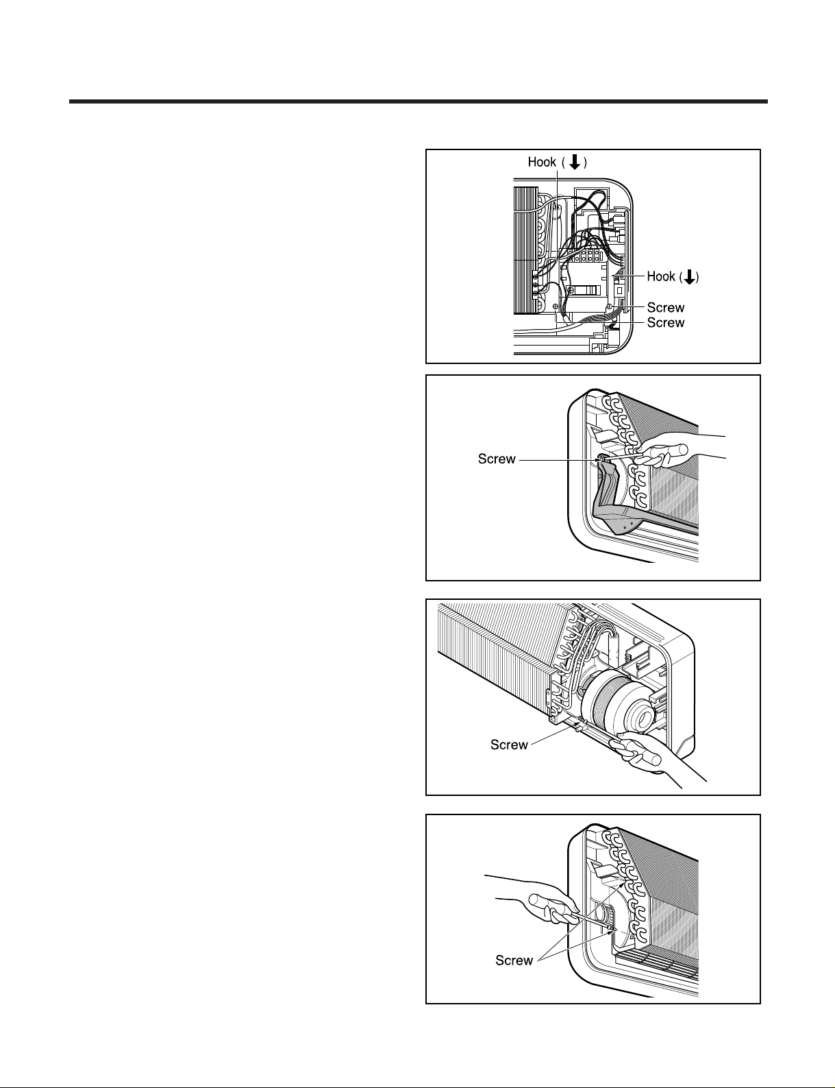
2. To remove the Control Box.
• Remove 2 securing screws.
• Pull the control box out from the chassis carefully.
3. To remove the Discharge Grille.
• Remove the securing screw.
• Pressing the right side of the discharge grille
downward slightly, unhook the discharge grille.
• Pull the discharge grille out from the chassis
carefully.
4. To remove the Evaporator.
• Remove 3 screws securing the evaporator(at the
left 1EA, at the right 2EA).
Page 3

- 40 -
• Unhook the tab on the right inside of the chassis
at the same time, slightly pull the evaporator
toward you until the tab is clear of the slot.
5. To remove the Cross-Flow Fan
• Loosen the screw securing the cross-flow fan to
the fan motor (do not remove).
• Lift up the right side of the cross-flow fan and the
fan motor, separate the fan motor from the
cross-flow fan.
• Remove the left end of the cross-flow fan from
the self-aligning bearing.
Page 4

Warning :
Disconnect the unit from power supply before making
any checks.
Be sure the power switch is set to “OFF”.
To remove the Grille from the Chassis
• Set the up-and-down air discharge louver to open
position (horizontally) by finger pressure.
• Remove the securing screws
• To remove the Grille, pull the lower left and right side
of the grille toward you (slightly tilted) and lift it
straight upward.
To remove the Grille from the Chassis
• Remove the cover control➀ from the grille➁.
• Separate the black lead wire from the white
connector.
• Remove screws secured (➂ 3 EA).
• Pull the grille➁ out from the chassis carefully.
1. To remove the sensor, housing connect, earth
conductor & step motor conductor with sensor
holder, Motor, Evaporator & P.C.B.
- 41 -
■ LS-K1824/1864/2466/2666CL/CM/CN/AL
Screw
(3EA)
Power
Conductor
Step Motor
Conductor
Earth
Conductor
Motor
Conductor
Sensor
Conductor
BLACK WHITE
1
3
2
Page 5

2. To remove the Control Box.
• Remove 2 securing screws.
• Pull the control box out from the chassis carefully.
3. To remove the Discharge Grille.
• Remove the securing screw.
• Pressing the right side of the discharge grille
downward slightly, unhook the discharge grille.
• Pull the discharge grille out from the chassis
carefully.
4. To remove the Evaporator.
• Remove 3 screws securing the evaporator(at the
left 1EA, at the right 2EA).
- 42 -
Page 6

• Unhook the tab on the right inside of the chassis
at the same time, slightly pull the evaporator
toward you until the tab is clear of the slot.
5. To remove the Cross-Flow Fan
• Loosen the screw securing the cross-flow fan to
the fan motor (do not remove).
• Lift up the right side of the cross-flow fan and the
fan motor, separate the fan motor from the
cross-flow fan.
• Remove the left end of the cross-flow fan from
the self-aligning bearing.
- 43 -
 Loading...