

LG A2UN186FA0, A3UN216FA0, A4UN306FA0 Schematic

Multi Type Room
Air Conditioner
SERVICE MANUAL
INDOOR UNIT: AMNN076L/M/NQA0
AMNN096L/M/NQA0
AMNN126L/M/NRA0
AMNN186L/M/NTA0
AMNN246L/M/NTA0
AMNN096APA0
AMNN126APA0
AMNN126TEA0
AMNN186TEA0
AMNN186VBA0
OUTDOOR UNIT: A2UN186FA0
A3UN216FA0
A4UN306FA0

Functions...................................................................................................................................... 3
Product Specifications.................................................................................................................6
Dimensions..................................................................................................................................10
Wiring Diagram ...........................................................................................................................15
Refrigeration Cycle Diagram......................................................................................................17
Operation Details ........................................................................................................................18
Display Function.........................................................................................................................34
Self-diagnosis Function .............................................................................................................34
Installation...................................................................................................................................35
Operation.....................................................................................................................................73
Disassembly of the parts (Indoor Unit).....................................................................................77
Valve service(3-way)...................................................................................................................86
Cycle Troubleshooting Guide ....................................................................................................90
Electronic Parts Troubleshooting Guide...................................................................................91
Electronic Control Device ........................................................................................................104
Schematic Diagram...................................................................................................................111
Exploded View and Replacement Parts List...........................................................................116
- 2 -
Contents
- 3 -
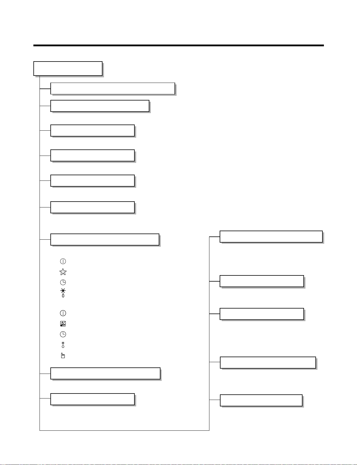
Functions
• Room temperature sensor. (THERMISTOR)
• Maintains the room temperature in accordance with the Setting Temp.
• Indoor fan is delayed for 5 seconds at the starting.
• Restarting is inhibited for approx. 3 minutes.
• Room/Art Cool/Convertible Type Indoor Unit: High, Med, Low, Chaos
• Cassette Type Indoor Unit: High, Mde, Low, Auto
Indoor Unit
Operation ON/OFF by Remote controller
Sensing the Room Temperature
Room temperature control
Starting Current Control
Time Delay Safety Control
Indoor Fan Speed Control
Operation indication Lamps (LED)
Soft Dry Operation Mode
• Both the indoor and outdoor fan
stops during deicing.
• Hot start after deice ends.
• The indoor fan stops until the
evaporator piping temperature will be
reached at 28°C.
Sleep Mode Auto Control
Natural Air Control by CHAOS Logic
Airflow Direction Control
Deice (defrost) control (Heating)
• The fan is switched to intermittent or irregular operation
• The fan speed is automatically switched
from high to low speed.
• Room/Art Cool/Convertible type Indoor Unit
-- Lights up in operation
-- Lights up in Sleep Mode
-- Lights up in Timer Mode
-- Lights up in Deice Mode
• Cassette type Indoor Unit
-- Lights up in Operation
-- Lights up in Filter replacement
-- Lights up in Timer Mode
-- Lights up in Defrost Mode or Hot Start Operation.
-- Operation procedures when the remote control
can't be used.
• Intermittent operation of fan at low speed.
•
The fan is switched to low(Cooling), med(Heating) speed.
• The unit will be stopped after 1, 2, 3, 4, 5, 6, 7 hours.
• The louver can be set at the desired position or swing up and down automatically.
•
The function will be operated while in any
operation mode with selecting the function.
• The function is to be stopped while it is
operating with selecting the function.
PLASMA
Hot-start Control (Heating)

- 4 -
• If power is on, it will operate to chage capacitor on controller and power relay will operate after about
10sec.
• The final operating freq. of comp. is set the lowest freq. that limited outdoor temp., discharge pipe temp.,
target freq., owing to CT.
• It will be changed the drive voltage of comp. according to operating frequency.
• It is only operated in the heating operation mode except defrosting operation.
• High speed/Low speed
Outdoor Unit
Power relay control
Comp. Freq. control
Overheatng. Protection(Power module)
Freq. speed control(up/down speed)
V/F control
Total current control (over current protection)
DC peak current control
4 way valve control
Outdoor fan motor control
Discharge pipe temp. control
Overpressure protection
- 5 -
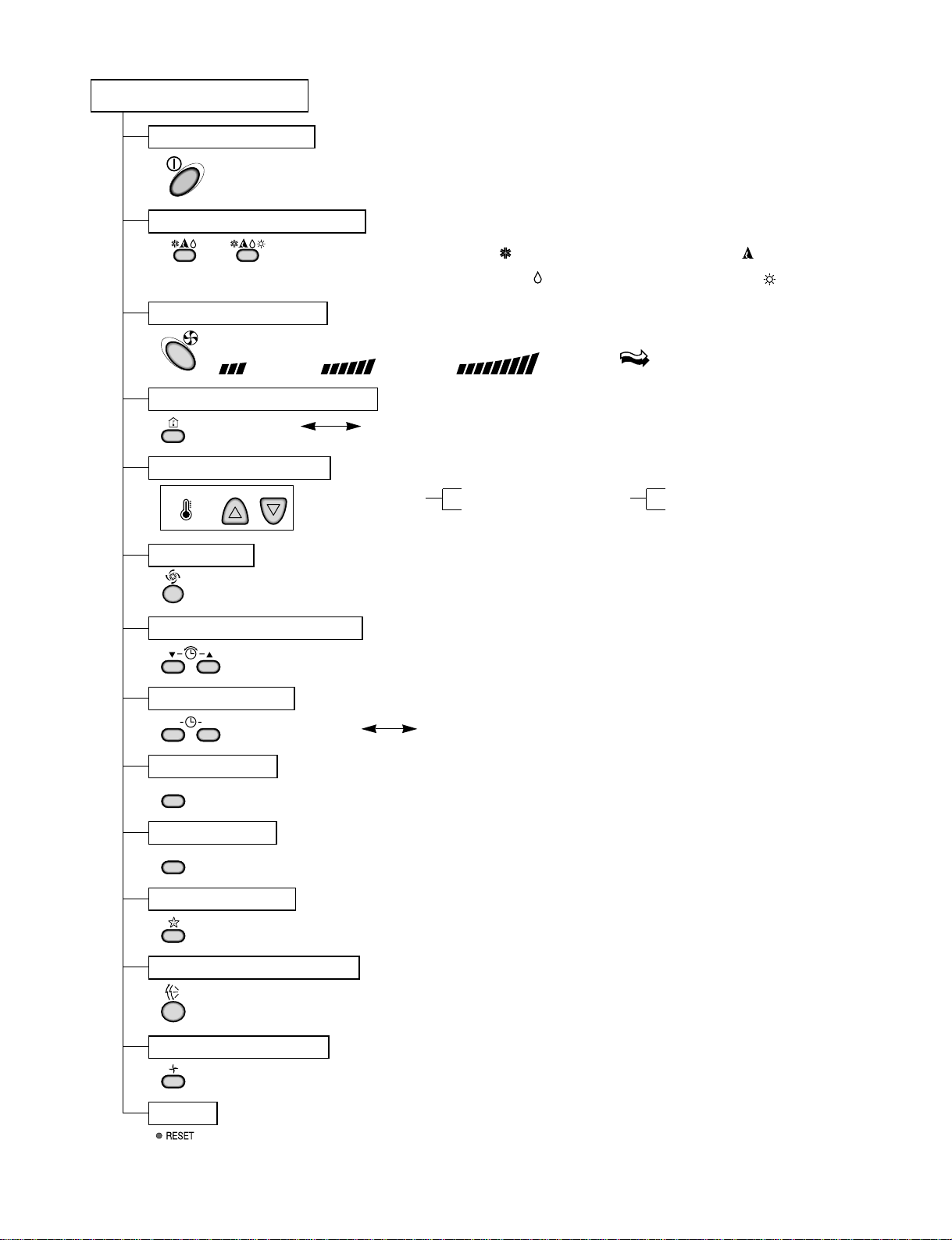
Remote Controller
JET COOL
Healthy Dehumidification Operation Mode.
( )
Operation Mode Selection
(Cooling
model only)
(Heating
model only)
Cooling Operation Mode.( )
Heating Operation Mode.( )
Auto Operation Mode.( )
Sleep Operation
Fan Operation Mode
Room, Temperature Display
Setting the Time or Timer
Airflow Direction Control
Operation ON/OFF
Temperature Setting
TEMPERATURE
LOWHIGH
Timer Selection
ON OFF
Timer Setting
SET
Timer Cancel
CANCEL
Reset
Fan Speed Selection
(Low) (Med) (High) (CHAOS)
: (High: 39°C LOW : 11°C)
Down to 18°C
Up to 30°C
Cooling
: OFF, ON, OFF ON
: Cancel Sleep Mode, Timer ON or Timer OFF
: 1, 2, 3, 4, 5, 6, 7, Off Timer
: Fan Operates without cooling or heating.
Down to 16°C
Up to 30°C
Heating

- 6 -
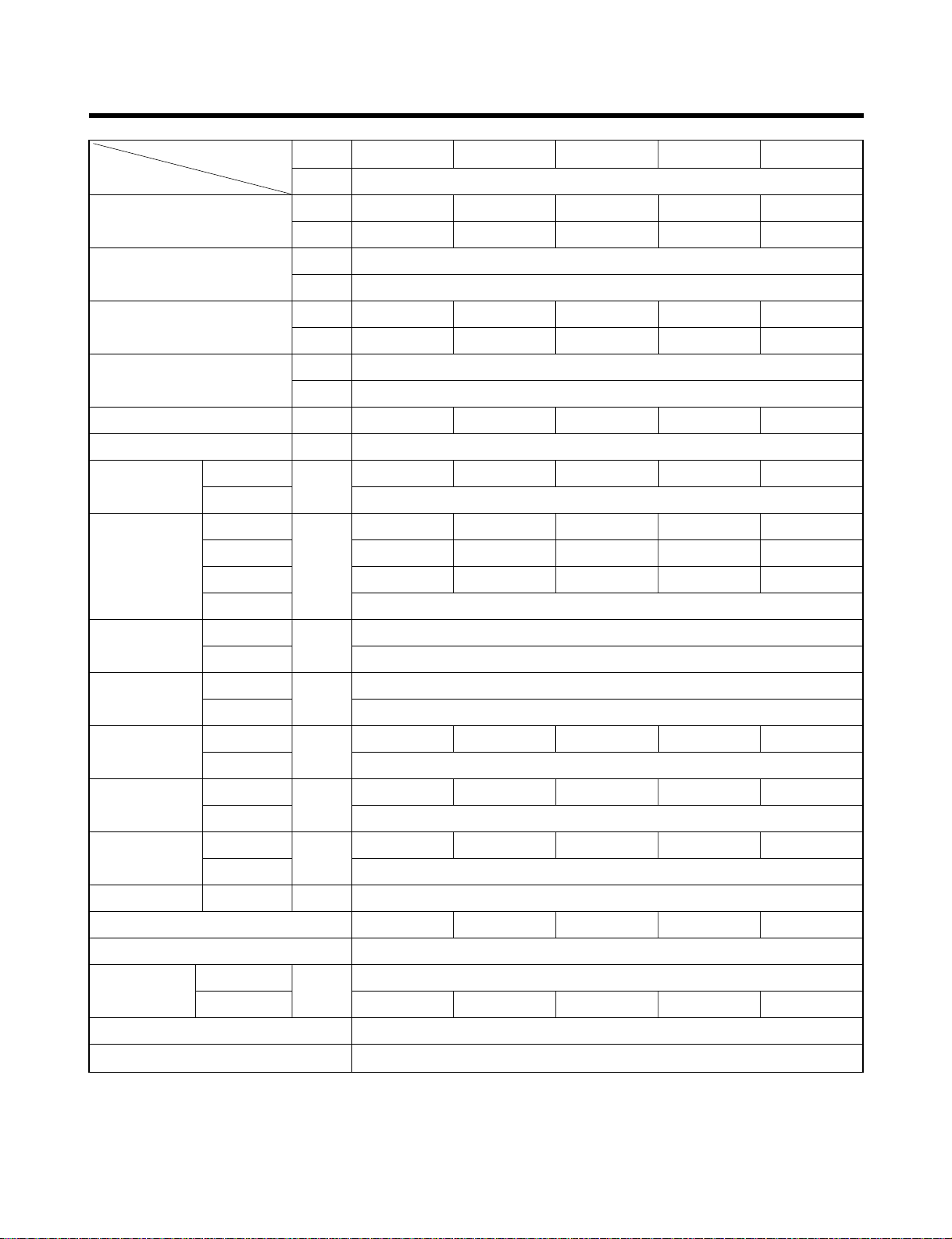
Product Specifications
AMNN076L/M/NQA0 AMNN096L/M/NQA0 AMNN126L/M/NRA0 AMNN186L/M/NTA0
A3-N216FA0/A2-N186FA0
Model
Item
Cooling Capacitor (Indoor)
Btu/h
W
Max. Cooling Capacitor (Outdoor)
Btu/h
W
Heating Capacitor (Indoor)
Btu/h
W
Max.
Heating Capacitor (Outdoor)
Btu/h
W
Moisture Removal l/h
Power Supply Ø, V, Hz
Air Circulation
Indoor, Max
CMM
Outdoor, Max
Indoor, High
Noise Level (1m)
Indoor, Med
dB(A)±1
Indoor, Low
Outdoor, Max
Input
Cooling
W
Heating
Running Current
Cooling
A
Heating
Motor Output
Indoor
W
Outdoor
Dimensions
Indoor mm
Outdoor (W*D*H)
Net Weight
Indoor
Kg
Outdoor
Refrigerant R-410A g
Airflow Direction Control(Up & Down)
Remocon Type
Service Valve
Luquid
inch(mm)
Gas
Sleeping Operation
Connection Cable
7,000 9,000 12,000 18,000
2,051 2,637 3,517 5,274
23,400
6,856
8,000 10,000 13,000 19,000
2,344 2,930 3,809 5,567
25,200
7,384
1.0 1.2 1.7 2.0
1, 220-240, 50
6.5 7.0 9.5 13
56
35 37 40 43
33 34 36 40
30 31 32 37
54
880~2,660
1,210~2,360
4.6~12.1
6.1~11.1
5.3 8.4 14.4 22
68
824 x155 x 260 824 x155 x 260 900 x 156 x 285 1090 x 172 x 314
870 x 320 x 655
77 812
64
1600(at 7.5m)
OO OO
L.C.D Wireless
1/4"(6.35)
3/8"(9.52) 3/8"(9.52) 1/2"(12.7) 1/2"(12.7)
O
O
Indoor
Outdoor
- 7 -
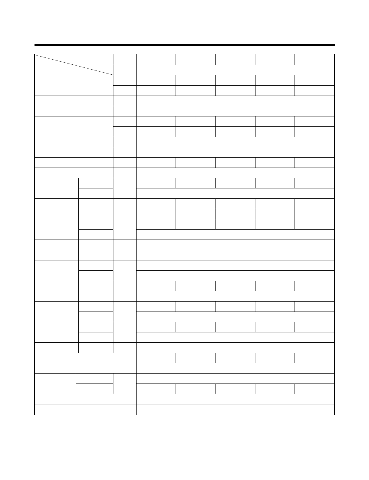
AMNN076L/M/NQA0 AMNN096L/M/NQA0 AMNN126L/M/NRA0 AMNN186L/M/NTA0 AMNN246L/M/NTA0
A4-N306FA0
Model
Item
Cooling Capacitor (Indoor)
Btu/h
W
Max. Cooling Capacitor (Outdoor)
Btu/h
W
Heating Capacitor (Indoor)
Btu/h
W
Max. Heating Capacitor (Outdoor)
Btu/h
W
Moisture Removal l/h
Power Supply Ø, V, Hz
Air Circulation
Indoor, Max
CMM
Outdoor, Max
Indoor, High
Noise Level (1m)
Indoor, Med
dB(A)±1
Indoor, Low
Outdoor, Max
Input
Cooling
W
Heating
Running Current
Cooling
A
Heating
Motor Output
Indoor
W
Outdoor
Dimensions
Indoor mm
Outdoor (W*D*H)
Net Weight
Indoor
Kg
Outdoor
Refrigerant R-410A g
Airflow Direction Control(Up & Down)
Remocon Type
Service Valve
Luquid
inch(mm)
Gas
Sleeping Operation
Connection Cable
7,000 9,000 12,000 18,000 23,000
2,051 2,637 3,517 5,274 6,739
31,000
9,083
8,000 10,000 13,800 19,000 26,000
2,344 2,930 4,044 5,567 7,618
34,000
9,962
1.0 1.2 1.7 2.0 2.5
1, 220-240, 50
6.5 7.0 9.5 13 14
60
35 37 40 43 47
33 34 36 40 44
30 31 32 37 40
58
1,430~3,800
1,950~3,910
7.0~19.5
9.3~20.0
5.3 8.4 14.4 22 29
68
824 x 155 x 260 824 x 155 x 260 900 x 156 x 285 1090 x 172 x 314 1090 x 172 x 314
870 x 320 x 800
7781212
75
2,000(at 7.5m)
OOOOO
L.C.D Wireless
1/4"(6.35)
3/8"(9.52) 3/8"(9.52) 1/2"(12.7) 1/2"(12.7) 1/2"(12.7)
O
O
Indoor
Outdoor

- 8 -
AMNN096APA0 AMNN126APA0 AMNN126TEA0 AMNN186TEA0 AMNN186VBA0
A3-N216FA0/A2-N186FA0
Model
Item
Cooling Capacitor (Indoor)
Btu/h
W
Max. Cooling Capacitor (Outdoor)
Btu/h
W
Heating Capacitor (Indoor)
Btu/h
W
Max. Heating Capacitor (Outdoor)
Btu/h
W
Moisture Removal l/h
Power Supply Ø, V, Hz
Air Circulation
Indoor, Max
CMM
Outdoor, Max
Indoor, High
Noise Level (1m)
Indoor, Med
dB(A)±1
Indoor, Low
Outdoor, Max
Input
Cooling
W
Heating
Running Current
Cooling
A
Heating
Motor Output
Indoor
W
Outdoor
Dimensions
Indoor mm
Outdoor (W*D*H)
Net Weight
Indoor
Kg
Outdoor
Refrigerant R-410A g
Airflow Direction Control(Up & Down)
Remocon Type
Service Valve
Luquid
inch(mm)
Gas
Sleeping Operation
Connection Cable
9,000 12,000 12,000 18,000 18,000
2,638 3,517 3,517 5,275 5,275
23,400
6,856
10,000 13,800 13,800 19,000 19,000
2,931 4,044 4,044 5,567 5,567
25,200
7,384
1.0 1.2 1.5 3.3 2.5
1, 220-240, 50
7.0 8.3 9.25 13.5 14
56
39 41 41 47 49
35 38 39 45 47
33 36 37 43 45
54
880~2,660
1,210~2,360
4.6~12.1
6.1~11.1
24 24 18.3 25 -
64
570 x 137 x 568 570 x 137 x 568 570 x 570 x 269 570 x 570 x 269 1,200 x 205 x 615
870 x 320 x 655
9 9 19 19 30
64
1,600
OOOOO
L.C.D Wireless
1/4"(6.35)
3/8"(9.52) 1/2"(12.7) 1/2"(12.7) 1/2"(12.7) 1/2"(12.7)
O
O
Indoor
Outdoor
- 9 -
AMNN096APA0 AMNN126APA0 AMNN126TEA0 AMNN186TEA0 AMNN186VBA0
A4-N306FA0
Model
Item
Cooling Capacitor (Indoor)
Btu/h
W
Max. Cooling Capacitor (Outdoor)
Btu/h
W
Heating Capacitor (Indoor)
Btu/h
W
Max. Heating Capacitor (Outdoor)
Btu/h
W
Moisture Removal l/h
Power Supply Ø, V, Hz
Air Circulation
Indoor, Max
CMM
Outdoor, Max
Indoor, High
Noise Level (1m)
Indoor, Med
dB(A)±1
Indoor, Low
Outdoor, Max
Input
Cooling
W
Heating
Running Current
Cooling
A
Heating
Motor Output
Indoor
W
Outdoor
Dimensions
Indoor mm
Outdoor (W*D*H)
Net Weight
Indoor
Kg
Outdoor
Refrigerant R-410A g
Airflow Direction Control(Up & Down)
Remocon Type
Service Valve
Luquid
inch(mm)
Gas
Sleeping Operation
Connection Cable
9,000 12,000 12,000 18,000 18,000
2,638 3,517 3,517 5,275 5,275
23,400
6,856
10,000 13,800 13,800 19,000 19,000
2,931 4,044 4,044 5,567 5,567
25,200
7,384
1.0 1.2 1.5 3.3 2.5
1, 220-240, 50
7.0 8.3 9.25 13.5 14
60
39 41 41 47 49
35 38 39 45 47
33 36 37 43 45
58
1,430~3,800
1,950~3,910
7.0~19.5
9.3~20.0
24 24 18.3 25 -
64
570 x 137 x 568 570 x 137 x 568 570 x 570 x 269 570 x 570 x 269 1,200 x 205 x 615
870 x 320 x 655
9 9 19 19 30
64
2,000(at 7.5m)
OOOOO
L.C.D Wireless
1/4"(6.35)
3/8"(9.52) 1/2"(12.7) 1/2"(12.7) 1/2"(12.7) 1/2"(12.7)
O
O
Indoor
Outdoor
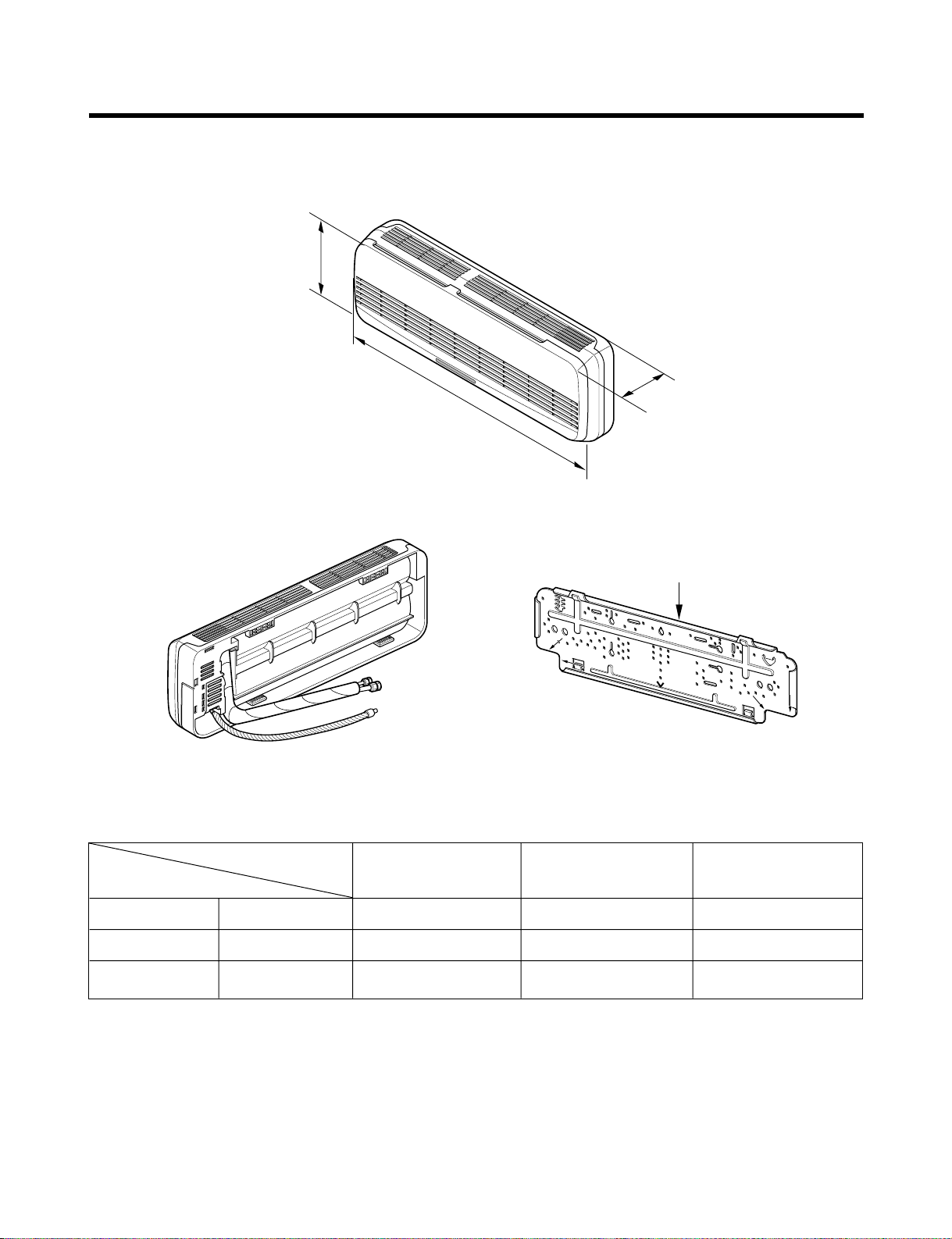
1. Indoor Unit
• Room Type Indoor Unit
- 10 -
Dimensions
Installation plate
D
H
W
W mm 824 900 1,090
H mm 260 285 314
D mm 155 156 172
7K, 9K Btu Series 12K Btu Series 18K, 24K Btu Series
MODEL
DIM
- 11 -
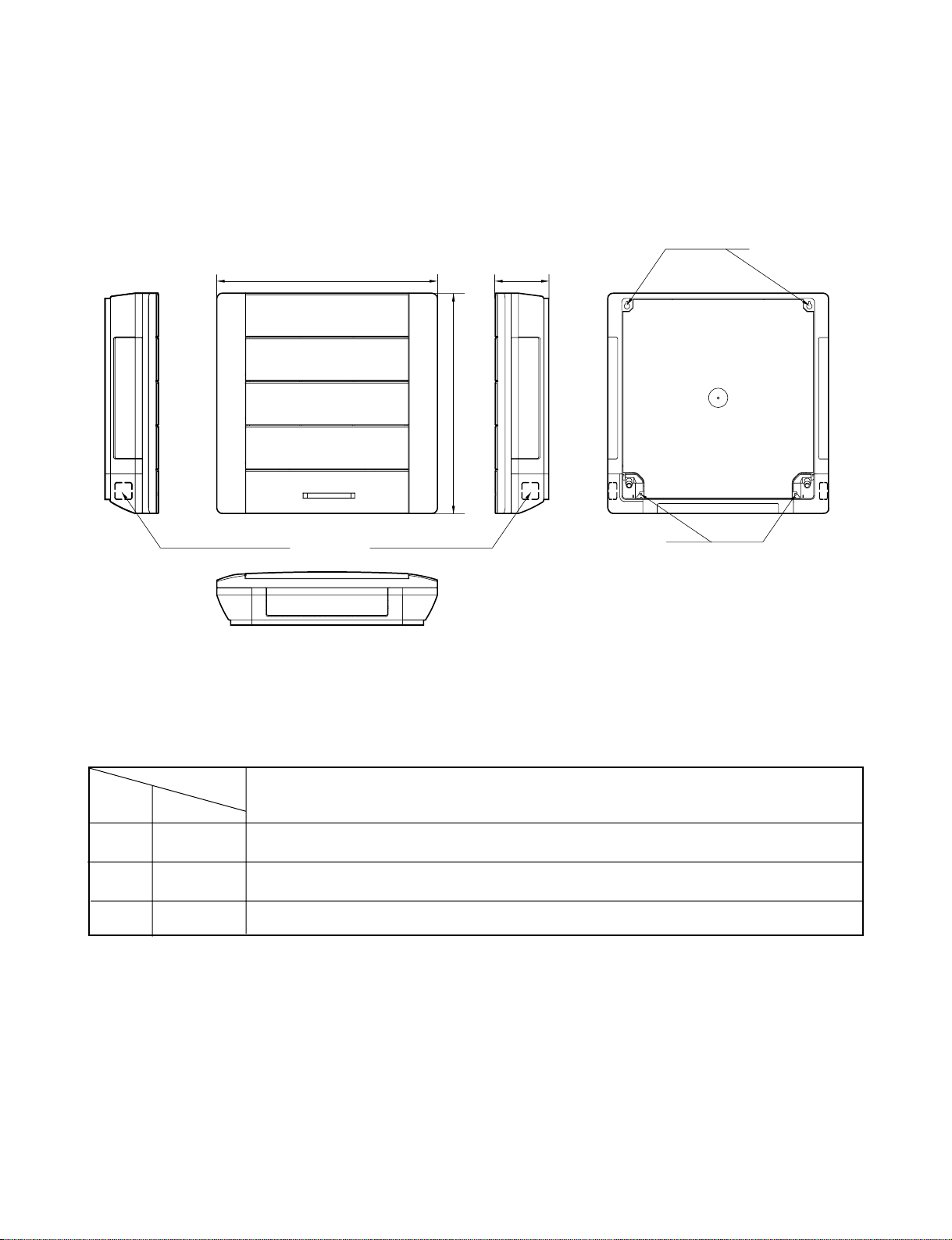
• Art Cool Type Indoor Unit
Pipe Hole
Fix Hole
Hanger Hole
H
W
D
MODEL
DIM Unit
W mm 570
H mm 568
D mm 137
INDOOR UNIT
- 12 -
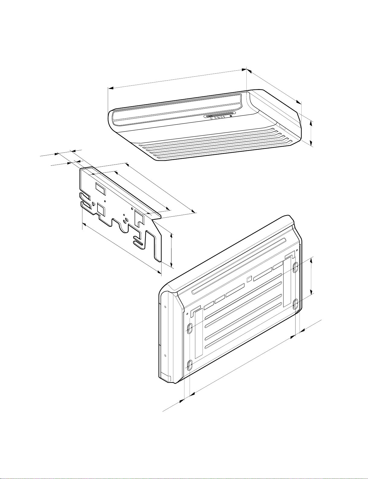
• Convertible Type Indoor Unit
250mm
36mm
36mm
1076mm
1200mm
205mm
615mm
392mm
265mm
468mm
R
63mm
38mm
175mm
(Installation Plate)
(Rear Side)
- 13 -
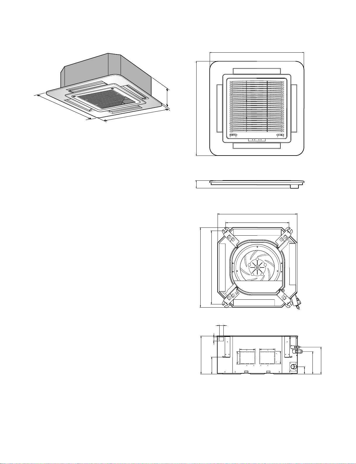
• Cassette Type Indoor Unit
269
67055
570
269
190.5
160
52
90
90
120.4
30
521
670
570
450
40
110 110
670
670
CLOSE OPEN OPEN CLOSE

- 14 -
W
D
L1
L2
L4
L3
H
L7L5L6
L10
L9
L9
L8
L10
W mm 870 870
H mm 655 800
D mm 320 320
L1 mm 370 370
L2 mm 25 25
L3 mm 630 775
L4 mm 25 25
L5 mm 546 546
L6 mm 160 160
L7 mm 160 160
L8 mm 53 53
L9 mm 50 50
L10 mm 40 40
A2UN186FA0/A3UN216FA0 A4UN306FA0
MODEL
DIM
2. Outdoor Unit
- 15 -
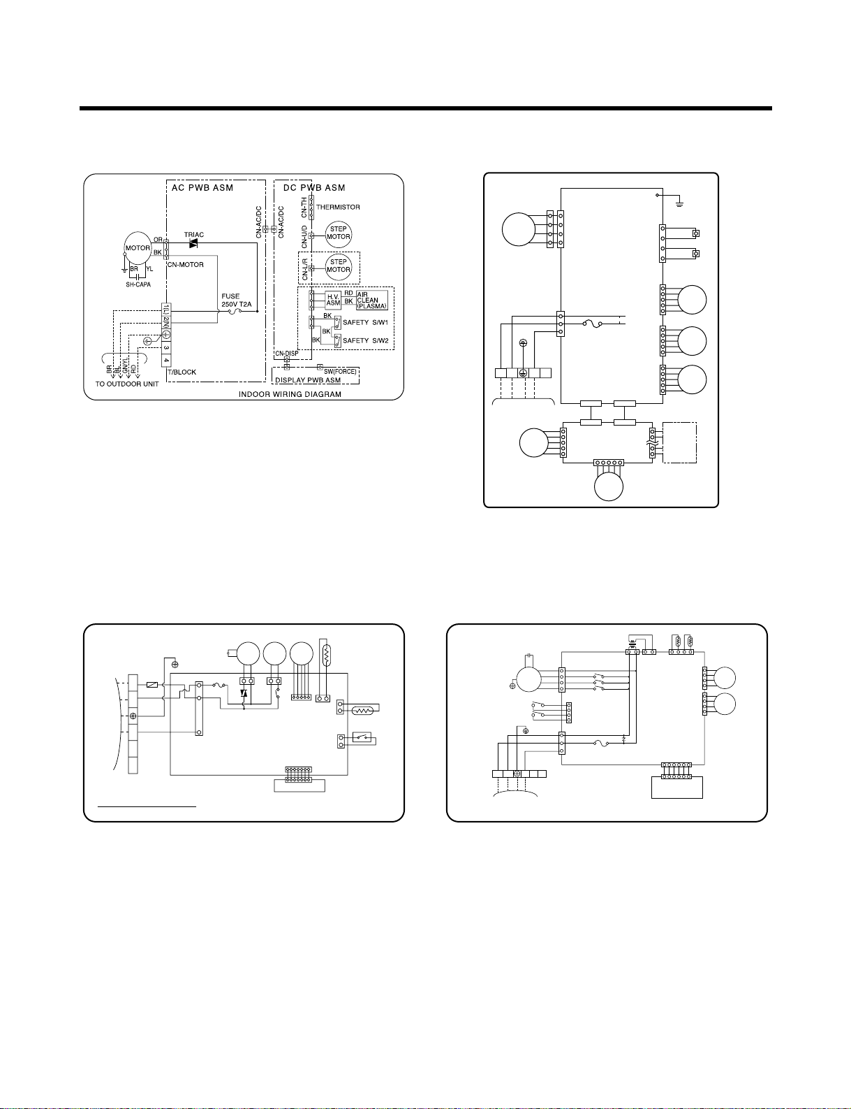
Wiring Diagram
1. Room Type Indoor Unit 2. Art Cool Type Indoor Unit
3. Cassette Type Indoor Unit 4. Convertible Type Indoor Unit
INDOOR WIRING DIAGRAM
CONNECT
PCB ASSY
DISPLAY
PCB
ASSY
MAIN PCB ASSY
CN-GND
CN-TH1CN-UDCN-LR1CN-LR2
CN-MOTOR2
CN-POWER
CN-D1
FUSE
250V 3.15A
CN-D2
BK
WH
YL
RD
FAN
MOTOR
STEP
MOTOR
STEP
MOTOR
STEP
MOTOR
STEP
MOTOR
STEP
MOTOR
TO OUTDOOR UNIT
BR
BL
GN/YL
RD
1(L) 2(N)
3854A20219A
34
Z
CAPACITOR
BR YL
CN-FAN
CN-POWER
RY-L
RY-M
RY-H
CN-TRANS
CN-UP/DOWN 1,2
TRANSFORMER
THERMISTOR
CN-TH
MAIN PCB
ASSY
OR
RD
RDBLBR
BL
BK
DOOR S/W 1,2
FUSE T3.15A
MOTOR
GN/YL
GN/YL
TO OUTDOOR UNIT
1(L)2(N)
4
3854A20220A
INDOOR WIRING DIAGRAM
CN-DISP
DISPLAY PCB
ASSY
TERMINAL
BLOCK
STEP
MOTOR
STEP
MOTOR
56
INDOOR WIRING DIAGRAM
INDOOR
MOTOR
DRAIN
PUMP
STEP
MOTOR
ROOM
SENSOR
PIPE
SENSOR
FLOAT S/W
CN - DISP
DISPLAY PCB
TERMINAL
BLOCK
TO OUTDOOR UNIT
3854A20221A
BR
YL
BK
OR
BL
BL
BR
RD
GN/YL
BL
3(L) 4(N) 5 6 7
FUSE T3.15A
FUSE
250V 5A
3854A20135F

BR
Comp.
U
UN
P
IPM
W
W
4WAY
V
V
RD
RD
YL
RD
RD
RD
RD
RD
BR
CT
BR
BR
BL
BL
WH
BK
BK
BK
BK BK
BK
BK
YL
H/P SWITCH
L/P SWITCH
OPTION
BRIDGE
DIODE
BRIDGE
DIODE
CAPACITOR
(400V,165µF)
400V,2500µF(DC LINK)
CAPACITOR
S.V
POWER
RELAY
BR
33331(L) 2(N) 1(L) 2(N) 1(L) 2(N)
BR
BR
BR
BR
BL
10
24
GN/YL
GN/YL
BL
BL
BL
BL
BL
GN/YL GN/YL
WH
WH
WH
BL
WH
WH
WH
(WH)
(RD)
(WH)
(RD)
GND
YL
YL
BR
BK
BK
NL
BK
WH
RD
BL
WH
BK
BL
CNGATE1
CNGATE2
CNIPM
CNIPM
CNGATE1
D-LEV
CN-DATA
CN-POWER CN-PWR
RY-START
250V, 3.15A
FUSE
RY-
PWR
CN-AC
REACTOR
POWER-OUT
FUSE
250V,25A
POWER-IN
A-LEV
B-LEV
C-LEV
(8PIN)
CN-LEV4CN-LEV1CN-LEV2CN-LEV3CN-TH6CN-TH5
CN-TH4
CN-TH3
CN-TH2
CN-TH1
COND
SENSOR
AIR
SENSOR
A-PIPE
SENSOR
B-PIPE
SENSOR
C-PIPE
SENSOR
D-PIPE
SENSOR
SUCTION
SENSOR
DISCHARGE
SENSOR
(7PIN) (9PIN)
CNGATE2
MAIN
PCB
CN-FAN
RY-LOW
RY-HIGH
CN-DC
CN-4WAY
CN-SV(H)CN-SV
WH
WH
WH
OPTION
TO INDOOR UNIT
MAIN POWER
1Ø, 220~240V, 50Hz
3854AP7050Z
D
C
BA
NOISE
FILTER
S.V
MOTOR
CAPACITOR
BL
BR YL
YL BR BL BK OR
BK
OR
- 16 -
4. Outdoor Unit
- 17 -
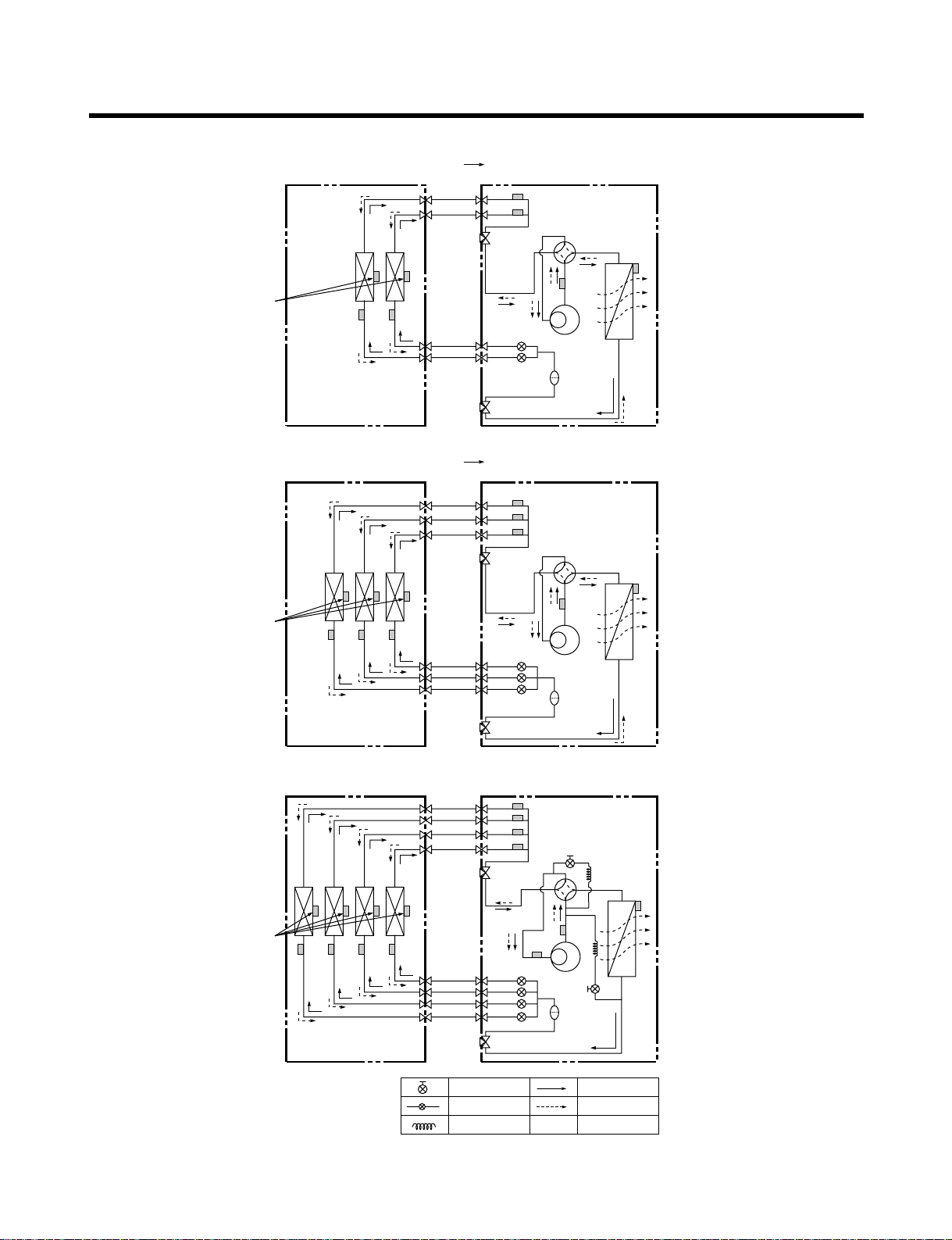
Refrigeration Cycle Diagram
ex)
LEV
Solenoid valve
Capillary tube
Cooling & Deice
Heating
Indoor Unit Outdoor Unit
UNIT-D UNIT-C UNIT-B UNIT-A
A-LEV
B-LEV
C-LEV
D-LEV
Gas side
Service Valve
Indoor
temperature
sensor
Heat
Exchanger
Heating
sensor
Solenoid
Valve
D-gas pipe sensor
C-gas pipe sensor
B-gas pipe sensor
A-gas pipe sensor
A-liquid pipe
sensor
B-liquid pipe
sensor
C-liquid pipe
sensor
D-liquid pipe
sensor
Liquid side
Service Valve
Strainer
Indoor Unit Outdoor Unit
UNIT-B UNIT-A
A-LEV
B-LEV
Gas side
Service Valve
Indoor
temperature
sensor
Comp
Heat
Exchanger
Heating
sensor
4-WAY VALVE
Discharge
pipe
sensor
Refrigerant flow
B-gas pipe sensor
A-gas pipe sensor
A-liquid pipe
sensor
B-liquid pipe
sensor
Liquid side
Service Valve
Strainer
Indoor Unit Outdoor Unit
UNIT-C UNIT-B UNIT-A
A-LEV
B-LEV
C-LEV
Gas side
Service Valve
Indoor
temperature
sensor
Comp
Heat
Exchanger
Heating
sensor
4-WAY VALVE
Discharge
pipe
sensor
C-gas pipe sensor
Refrigerant flow
B-gas pipe sensor
A-gas pipe sensor
A-liquid pipe
sensor
B-liquid pipe
sensor
C-liquid pipe
sensor
Liquid side
Service Valve
Strainer
Comp
Section pipe
sensor
Discharge
pipe
sensor
1. A2-N186FA0
2. A3-N216FA0
3. A4-N306FA0

-18-
Operation Details
1. Room/Art Cool Type Indoor Unit
(1) The Function of main control
• DISPLAY
Operation Indicator
• On while in appliance operation, off while in appliance pause
• Flashing while in disconnection or short in Thermistor (3 sec off / 0.5 sec on)
Sleep Timer Indicator
• On while in sleep timer mode, off when sleep timer cancel or appliance operation pause
Timer Indicator
• On while in timer mode (on/off), off when timer mode is completed or canceled
Defrost Indicator
• Off except when hot start during heating mode operation or while in defrost control
■ Cooling Mode Operation
• When the intake air temperature reaches 0.5°C below the setting temp, the compressor and the outdoor fan
stop.
• When it reaches 0.5°C above the setting temp, they start to operate again.
Compressor ON Temp ➲ Setting Temp+0.5°C
Compressor OFF Temp ➲ Setting Temp-0.5°C
• While in compressor running, operating with the airflow speed set by the remote control. While in compressor
not running, operating with the low airflow speed regardless of the setting.
■ Soft Dry Operation Mode
• When the dehumidification operation input by the remote control is received, the intake air temperature is
detected and the setting temp is automatically set according to the intake air temperature.
26°C ≤ Intake Air Temp ➲ 25°C
24°C ≤ Intake Intake Air Temp<26°C ➲ Intake Air Temp-1°C
18°C ≤ Intake Intake Air Temp<24°C ➲ Intake Air Temp-0.5°C
Intake Air Temp<18°C ➲ 18°C
• While in compressor off, the indoor fan repeats low airflow speed and pause.
• While the intake air temp is between compressor on temp. and compressor off temp., 10-min dehumidification
operation and 4-min compressor off repeat.
Compressor ON Temp. ➲ Setting Temp+0.5°C
Compressor OFF Temp. ➲ Setting Temp-0.5°C
• In 10-min dehumidification operation, the indoor fan operates with the low airflow speed.
■ Heating Mode Operation
• When the intake air temp reaches +3°…above the setting temp, the compressor is turned off. When below
the setting temp, the compressor is turned on.
Compressor ON Temp. ➲ Setting Temp.
Compressor OFF Temp. ➲ Setting Temp.+3°C
• While in compressor on, the indoor fan is off when the indoor pipe temp. is below 26°C, when above 28°C , it
operates with the low or setting airflow speed.

-19-
• While in compressor off, the indoor fan is off when the indoor pipe temp is below 33°C, when above 35°C , it
operates with the low airflow speed.
• If overloaded while in heating mode operation, in order to prevent the compressor from OLP operation, the
outdoor fan is turned on/off according to the indoor pipe temp.
• While in defrost control, both of the indoor and outdoor fans are turned off.
■ Defrost Control
• Defrost operation is controlled by timer and sensing temperature of outdoor pipe.
• The first defrost starts only when the outdoor pipe temperature falls below -5°C after 40 minutes passed from
starting of heating operation and more than 10 minutes operation of compressor.
• Defrost ends after 12 minutes passed from starting of defrost operation or after the outdoor fan operates within max. 2 minutes 30 seconds when the outdoor pipe temperature rises over 12°C even it before 12 minutes.
• The second defrost starts only when the outdoor pipe temperature falls below -5°C after 40 minutes passed
from ending of the first defrost and more than 10 minutes operation of compressor.
■ Fuzzy Operation
• When any of operation mode is not selected like the moment of the power on or when 3 hrs has passed since
the operation off, the operation mode is selected.
• When determining the operation mode, the compressor, the outdoor fan, and the 4 way valve are off and only
the indoor fan is operated for 15 seconds. Then an operation mode is selected according to the intake air
temp at that moment as follows.
24°C ≤ Inatake Air Temp ➲ Fuzzy Operation for Cooling
21°C ≤ Inatake Air Temp<24°C ➲ Fuzzy Operation for Dehumidification
Inatake Air Temp<21°C ➲ Fuzzy Operation for Heating
• If any of the operation modes among cooling / dehumidification / heating mode operations is carried out for 10
sec or longer before Fuzzy operation, the mode before Fuzzy operation is operated.
1) Fuzzy Operation for Cooling
• According to the setting temperature selected by Fuzzy rule, when the intake air temp is 0.5°C or more below
the setting temp, the compressor is turned off. When 0.5°C or more above the setting temp, the compressor
is turned on.
Compressor ON Temp ➲ Setting Temp +0.5°C
Compressor OFF Temp ➲ Setting Temp – 0.5°C
• At the beginning of Fuzzy mode operation, the setting temperature is automatically selected according to the
intake air temp at that time.
26°C≤ Intake Air Temp ➲ 25°C
24°C≤ Intake Air Temp<26°C ➲ Intake Air Temp – 1°C
22°C≤ Intake Air Temp<24°C ➲ Intake Air Temp – 0.5°C
18°C≤ Intake Air Temp<22°C ➲ Intake Air Temp
Intake Air Temp<18°C ➲ 18°C
• When the Fuzzy key (Temperature Control key) is input after the initial setting temperature is selected, the
Fuzzy key value and the intake air temperature at that time are compared to select the setting temperature
automatically according to the Fuzzy rule.
• While in Fuzzy operation, the airflow speed of the indoor fan is automatically selected according to the temperature.

-20-
2) Fuzzy Operation for Dehumidification
• According to the setting temperature selected by Fuzzy rule, when the intake air temp is 0.5°C or more below
the setting temp, the compressor is turned off. When 0.5°C or more above the setting temp, the compressor
is turned on.
Compressor ON Temp ➲ Setting Temp + 0.5°C
Compressor OFF Temp ➲ Setting Temp – 0.5°C
• At the beginning of Fuzzy mode operation, the setting temperature is automatically selected according to the
intake air temp at that time.
26°C ≤ Intake Air Temp ➲ 25°C
24°C ≤ Intake Air Temp<26°C ➲ Intake Air Temp – 1°C
22°C ≤ Intake Air Temp<24°C ➲ Intake Air Temp – 0.5°C
18°C ≤ Intake Air Temp<22°C ➲ Intake Air Temp
Intake Air Temp<18°C ➲ 18°C
• When the Fuzzy key (Temperature Control key) is input after the initial setting temperature is selected, the
Fuzzy key value and the intake air temperature at that time are compared to select the setting temperature
automatically according to the Fuzzy rule.
• While in Fuzzy operation, the airflow speed of the indoor fan repeats the low airflow speed or pause as in
dehumidification operation.
3) Fuzzy Operation for Heating
• According to the setting temperature selected by Fuzzy rule, when the intake air temp is 3°C or more above
the setting temp, the compressor is turned off. When below the setting temp, the compressor is turned on.
Compressor ON Temp ➲ Setting Temp
Compressor OFF Temp ➲ Setting Temp + 3°C
• At the beginning of Fuzzy mode operation, the setting temperature is automatically selected according to the
intake air temp at that time.
20°C≤Intake Air Temp ➲ Intake Air Temp + 0.5°C
Intake Air Temp<20°C ➲ 20°C
• When the Fuzzy key (Temperature Control key) is input after the initial setting temperature is selected, the
Fuzzy key value and the intake air temperature at that time are compared to select the setting temperature
automatically according to the Fuzzy rule.
• While in Fuzzy operation, the airflow speed of the indoor fan is set to the high or the medium according to the
intake air temperature and the setting temperature.
■ Airflow Speed Selection
• The airflow speed of the indoor fan is set to high, medium, low, or chaos (auto) by the input of the airflow
speed selection key on the remote control.
■ On-Timer Operation
• When the set time is reached after the time is input by the remote control, the appliance starts to operate.
• The timer LED is on when the on-timer is input. It is off when the time set by the timer is reached.
• If the appliance is operating at the time set by the timer, the operation continues.
While in Fuzzy operation, the airflow speed of the indoor fan is automatically selected according to the temperature.
■ Off-Timer Operation
• When the set time is reached after the time is input by the remote control, the appliance stops operating.
• The timer LED is on when the off-timer is input. It is off when the time set by the timer is reached.
• If the appliance is on pause at the time set by the timer, the pause continues.

-21-
■ Off-Timer <=> On-Timer Operation
• When the set time is reached after the on/off time is input by the remote control, the on/off-timer operation is
carried out according to the set time.
■ Sleep Timer Operation
• When the sleep time is reached after <1,2,3,4,5,6,7,0(cancel) hr> is input by the remote control while in appliance operation, the operation of the appliance stops.
• While the appliance is on pause, the sleep timer mode cannot be input.
• While in cooling mode operation, 30 min later since the start of the sleep timer, the setting temperature
increases by 1°C. After another 30 min elapse, it increases by 1°C again.
• When the sleep timer mode is input while in cooling cycle mode, the airflow speed of the indoor fan is set to
the low.
• When the sleep timer mode is input while in heating cycle mode, the airflow speed of the indoor fan is set to
the medium.
■ Chaos Swing Mode
• By the Chaos Swing key input, the upper/lower vane automatically operates with the Chaos Swing or they are
fixed to the desired direction.
• While in Chaos Swing mode, the angles of cooling and heating cycle operations are different.
■ Chaos Natural Wind Mode
• When the Chaos Natural Wind mode is selected and then operated, the high, medium, or low speed of the airflow mode is operated for 2~15 sec. randomly by the Chaos Simulation.
■ Jet Cool Mode Operation
• While in heating mode or Fuzzy operation, the Jet Cool key cannot be input. When it is input while in the
other mode operation (cooling, dehumidification, ventilation), the Jet Cool mode is operated.
• In the Jet Cool mode, the indoor fan is operated at super-high speed for 30 min at cooling mode operation.
• In the Jet Cool mode operation, the room temperature is controlled to the setting temperature, 18°C.
• When the sleep timer mode is input while in the Jet Cool mode operation, the Jet Cool mode has the priority.
• When the Jet Cool key is input, the upper/lower vanes are reset to those of the initial cooling mode and then
operated in order that the air outflow could reach further.
■ Auto Restarting Operation
• When the power is restored after a sudden power failure while in appliance operation, the mode before the
power failure is kept on the memory and the appliance automatically operates in the mode on the memory.
• The slide switch on the main unit of the appliance should be on the Auto Restarting position in order that the
Auto Restarting operation is available.
• Operation Mode that is kept on the memory
- State of Operation ON/OFF
- Operation Mode/Setting Temp/Selected Airflow Speed
- Sleep Timer Mode/Remaining Time of Sleep Timer (unit of hour)
• Incase the power comes on again after a power failure,
Auto Restarting operation is the function to operate procedures
automatically to the previous operating conditions. (Art Cool Type)

-22-
■ Forced Operation
• To operate the appliance by force in case that the remote control is lost, the forced operation selection switch
is on the main unit of the appliance to operate the appliance in the standard conditions.
• When the power is supplied while the slide switch is on the forced operation position, or when the slide switch
position is switched to the Auto Restarting (or test operation) position or switched from the remote control
position to the forced operation position while the power is on, the forced operation is carried out.
• When the slide switch position is switched from the forced operation position to the Auto Restarting position or
the remote control position, the forced operation is canceled and the appliance stops operating.
• In the forced operation mode, the indoor fan is operated at low speed for around 15 sec and then the operation condition is set according to the intake air temperature as follows.
24°C≤Intake Air Temp ➲ Cooling Mode Operation, 22°C, High Speed
21°C≤Intake Air Temp<24°C ➲ Dehumidification Operation, 23°C, High Speed
Intake Air Temp<21°C ➲ Heating Mode Operation, 24°C, High Speed
■ Remote Control Operation Mode
• When the remote control is selected by the slide switch on the main unit, the appliance operates according to
the input by the remote control.
■ Protection of the evaporator pipe from frosting
• If the indoor pipe temp is below 0°C in 7 min. after the compressor operates without any pause while in cooling cycle operation mode, the compressor and the outdoor fan are turned off in order to protect the indoor
evaporator pipe from frosting.
• When the indoor pipe temp is 7°C and higher after 3 min. pause of the compressor, the compressor and the
outdoor fan is turned on according to the condition of the room temperature.
■ Buzzer Sounding Operation
• When the appliance-operation key is input by the remote control, the short "beep-beep-" sounds.
• When the appliance-pause key is input by the remote control, the long "beep—" sounds.
- 23 -
2. Cassette Type Indoor Unit
(1) The function of main control
■ Time Delay Safety Control
• 3 min
...
The compressor is ceased for 3minutes to balance the pressure in the refrigeration cycle.
(Protection of compressor)
• 5 sec
...
Vertical air flow direction control louvers open in 5 seconds to prevent noise between louvers and wind.
• 5 sec
...
The 4-way valve is ceased for 5 sec. to prevent the refrigerant-gas abnormal noise when the Heating
operation is OFF or switched to the other operation mode when compress is off.
While compressor is running, it takes 3~5 seconds to switch.
■ Auto Swing Control
• This function is to swing the louver up and down automatically.
■ Soft-Dry Operation
• The indoor fan speed is automatically set to the low, so the shift of the indoor fan speed is impossible because of
already being set to the best speed for Dry Operation by Micom Control.
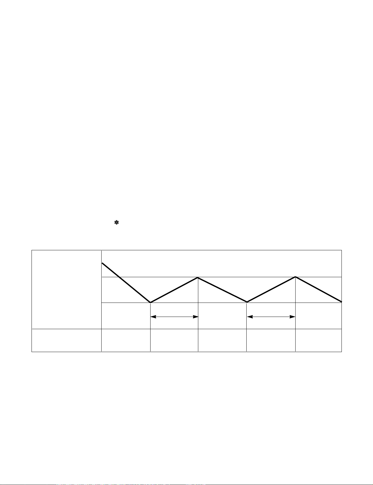
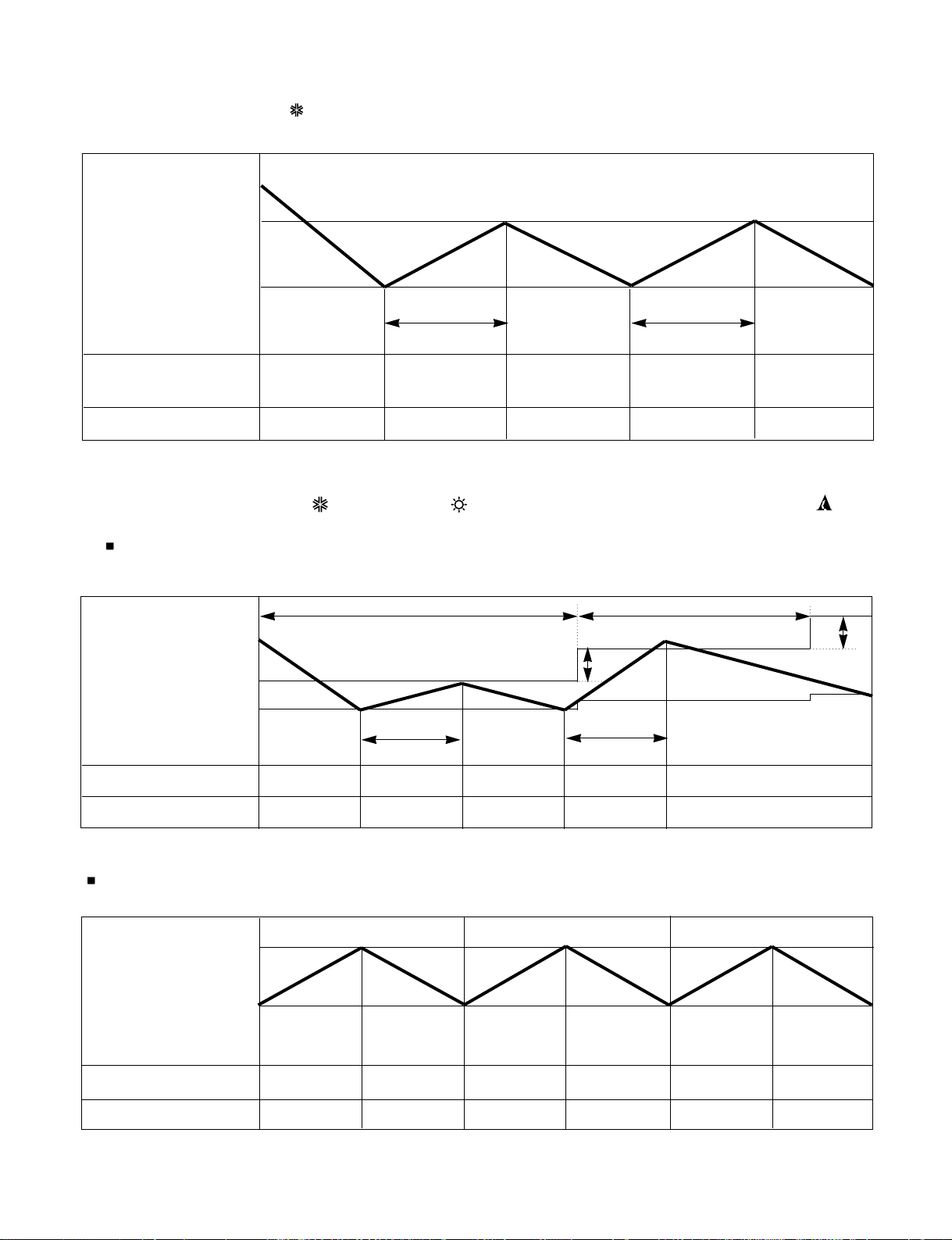
■ Cooling Mode Operation
• When selecting the Cooling( ) Mode Operation, the unit will operate according to the setting by the remote
controller and the operation diagram is as following
Intake Air temp.
COMP. ON
(SET TEMP.+0.5°C)
COMP. OFF
(SET TEMP. -0.5°C) More than More than
3 minutes 3 minutes
Selecting Selecting Selecting
fan speed fan speed fan speed
INDOOR FAN Low Low

- 24 -
Intake Air temp.
Setting temp.+3°C
(Compressor OFF)
Setting temp.
(Compressor ON)
INDOOR FAN Low OFF Low Low OFF
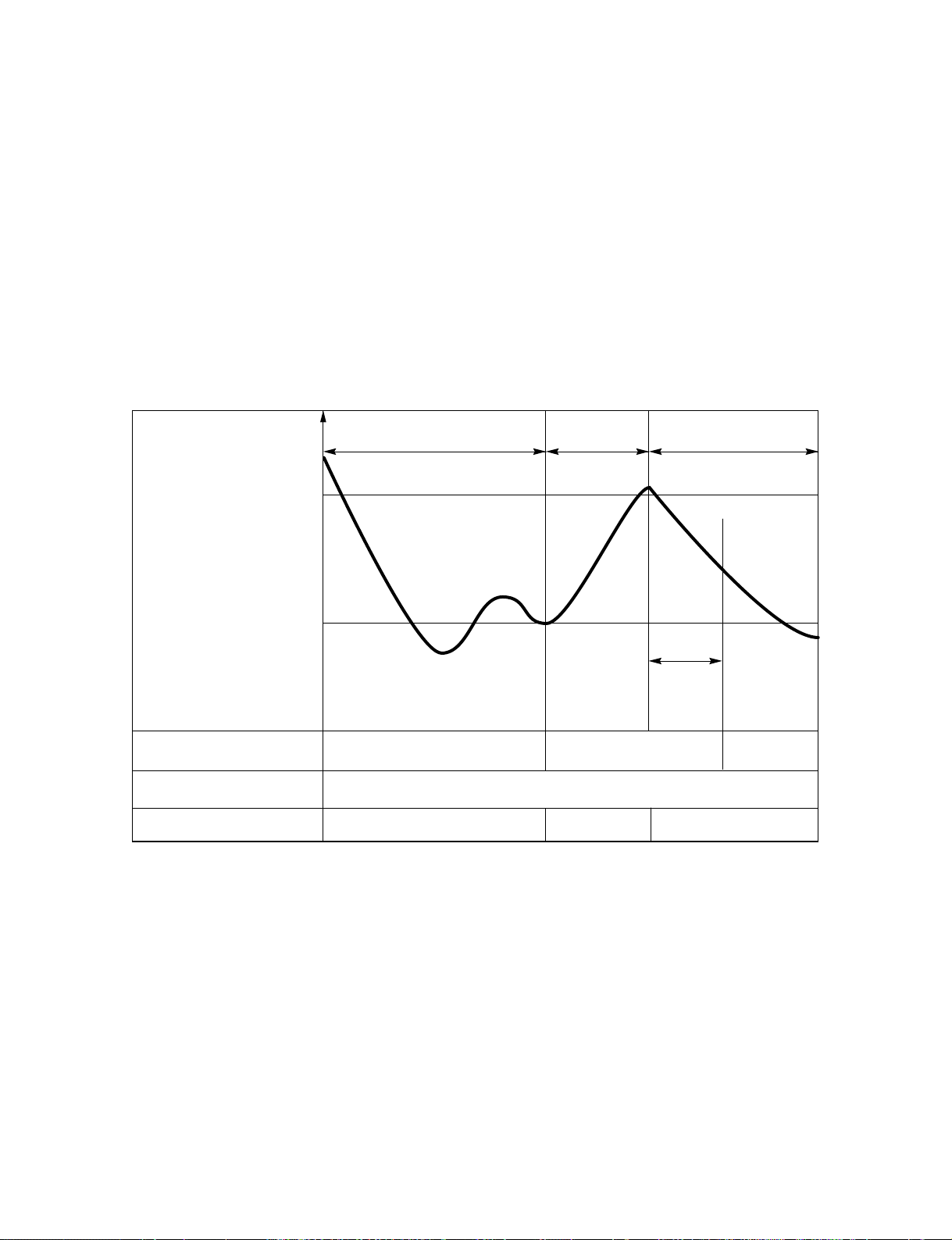
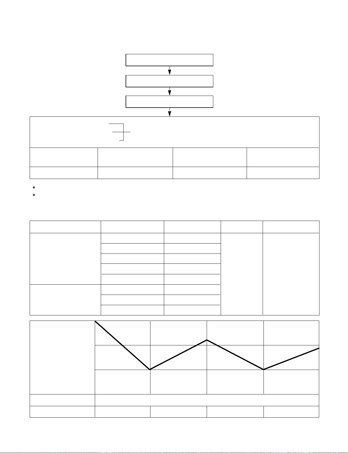
■ Heating Mode Operation
The unit will operate according to the setting by the remote controller and the operation diagram is shown as following.
Hot Start
Low
Selecting
Fan Speed
minimum 3min
Selecting fan
speed
minimum
10sec.
1min
AA
minimum
1min.
minimum
10sec.
B
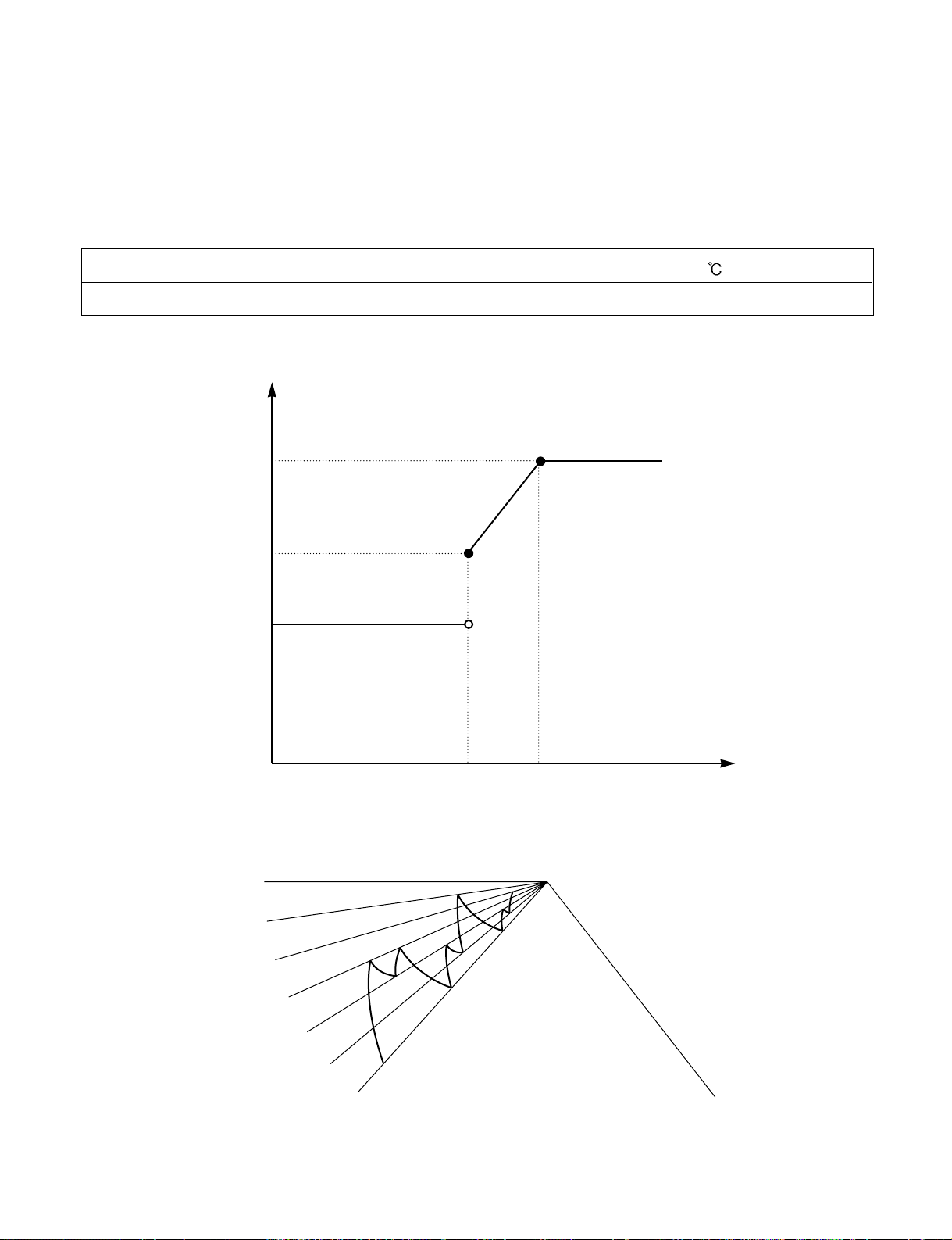
■ Hot-Start Control
The indoor fan stops until the evaporator piping temperature will be reached to 25°C.
The operation diagram is as following.
PIPING
TEMPERATURE
1min
COMPRESSOR
INDOOR FAN OFF LOW
Selected Fan
ON
22°C
25°C
• A point; While the indoor Heat-Exchanger temperature is higher than 40°C fan operates at low speed, when
it becomes lower than 40˚C fan stops.
• B point; When the indoor Heat-Exchanger temperature is higher than 31°C, fan operates at selected fan
speed, when it becomes lower than 31°C, the fan operates at low speed for 10sec, after 10sec, it
operates at selected fan speed.
- 25 -
■ Defrost Control
• While in heating mode operation in order to protect the evaporator pipe of the outdoor unit from freezing, reversed to
cooling cycle to defrost the evaporator pipe of the outdoor unit.
• Defrost control is available 45 min. later since heating mode operation started, and it will not prolong over 10 min.
• Defrost control is carried out according to the following priority order while in heating mode operation.
1st priority : Defrost control is carried out according to the indoor pipe temp 60 min. later since heating mode opera-
tion started.
2nd priority : The temp differences between the indoor pipe temp and the intake air temp 25 min. later(∆T1) and 45
min. later (∆T2) since heating mode operation started are measured, then defrost control is carried out
according to the dirrerence (∆T=∆T1-∆T2)
3rd priority : Defrost control is carried out according to the temp difference (E=TE1-TE2) between the indoor pipe
temperatures of 25 min later(TE1) and 45 min later (TE2) after heating mode operation started.
• When the indoor pipe temp is 41°C or above, defrost control is not carried out even if the condition is one of the
defrost conditions above.
• While in defrost control, the compressor is on and the indoor fan, the outdoor fan, and the 4 way valve are off.
More than 45 minutes
of heating operation
Within
9min. 45sec.
ON OFF
ON
ON
ON OFF
COMPRESSOR
4-WAY VALVE
INDOOR FAN
-6°C ON
12°C OFF
The outdoor
piping Temp.
More than 10 min.
running of compressor
More than 45 minutes
of heating operation
HOT-
START
ON

- 26 -
3. Convertible Type Indoor Unit
(1) The function of main control
■ Time Delay Safety Control
• 3min…The compressor is ceased for 3minutes to balance the pressure in the refrigeration cycle.
(Protection of compressor)
• 5sec…Vertical air flow direction control louvers open in 5 seconds to prevent noise between louvers and wind.
• 30sec… The 4-way valve is ceased for 30sec. to prevent the refrigerant-gas abnormal noise when the Heating
operation is OFF or switched to the other operation mode while compress is off.
While compressor is running, it takes 3~5 seconds to switch.
■ Airflow Direction Control
• This function is to swing the louver up and down automatically and to set it at the desired position.
• The procedure is as the following.
1st ; Press the ON/OFF Button to operate the product.
2nd ; Press the Airflow Direction Control Button to swing the louver up and down automatically.
3nd ; Repress the Airflow Direction Control Button to set the louver as the desired position.
MODE0
1
2
3
4
5
6
7
135°
Cooling
MODE
MODE
MODE
MODE
MODE
MODE
MODE
9
MODE
(CLOSE)
OPEN
135°
12°
Cooling
HeatingHeatingHeating
MODE 1
MODE 2
MODE 3
MODE 4
MODE 5
MODE 6
MODE 7
MODE 8
MODE 9
CLOSE
Heating
Heating
Heating
For Heating Model
• Airflow direction control figure when installed on
the floor.
• Airflow direction control figure when installed
under the ceiling.
OPEN
MODE 1
MODE 2
MODE 3
MODE 4
MODE 5
MODE 6
MODE 7
MODE 8
Cooling
MODE 9
CLOSE
Heating
Heating
12°
135°
OPEN
MODE 1
MODE 2
Cooling
MODE 3
MODE 4
MODE 5
MODE 6
MODE 7
MODE 8
MODE 9
CLOSE
Heating
Heating
12°
135°
- 27 -
3. Cooling Mode Operation
• When selecting the Cooling( ) Mode Operation, the unit will operate according to the setting by the remote controller and the operation diagram is as following
4. Cooling or Heating Mode with Sleep Mode Auto Operation
• When selecting the Cooling( ) or the Heating( ) combined with the Sleep Mode Auto Operation( ), the
operation diagram is as following.
Cooling Mode with the Sleep Mode
• The setting temperature will be raised by 1°C 30minutes later and by 2°C 1 hour later.
• The operation will be stopped after 1, 2, 3, 4, 5, 6, 7 hours.
Heating Mode with the Sleep Mode.
• The operation will be stopped after 1, 2, 3, 4, 5, 6, 7 hours.
Intake Air temp.
COMP. ON
(SET TEMP.+0.5°C)
COMP. OFF
(SET TEMP. -0.5°C) More than More than
3 minutes 3 minutes
INDOOR FAN Low Low Low Low Low
COMPRESSOR ON OFF ON OFF ON
30 minutes 30 minutes
1°C
1°C
Setting Temp. +3°C
(Compressor OFF)
Setting Temp.
(Compressor ON)
Indoor Fan Low. Low. Low. Low. Low. Low.
Compressor ON OFF ON OFF ON OFF
Intake Air temp.
COMP. ON
(SET TEMP.+0.5°C)
COMP. OFF
(SET TEMP. -0.5°C) More than More than
3 minutes 3 minutes
Selecting Selecting Selecting
fan speed fan speed fan speed
COMPRESSOR ON OFF ON OFF ON
INDOOR FAN Low Low
- 28 -
5. Auto Operation
• The operation procedure is as following. (Cooling & Heating Model)
If initial mode is decided, that mode is continued without the room temperature changing.
For cooling operation mode over 24°C setting temperature and fan speed are same as cooling only model.
• Auto Operation for Cooling. (Cooling only Model)
Press Start/Stop Button
Select Auto Operation Mode
Check the Room temperature
Operation mode
Indoor fan speed are automatically decided by Fuzzy rule.
Setting temperature
Intake-air
temperature
Operation Mode Heating Soft Dry Cooling
Operation Condition Intake-air Temperature Setting temperature Fan speed Air Direction Control
Over 26°C25°C
Over 24°C~below 26°C Intake air -1°C
Over 22°C~below 24°C Intake air -0.5°C
Over 20°C~below 22°C intake air temperture
below 20°C20°C
Over 20°C~below 30°C Fuzzy control
below 20°C20°C
over 30°C30°C
below 21°C
below
24°C
~
Over 24°C
Over
21°C
When Auto Operation
initial start
When pressing room temperature setting button
during Auto Operation
Controlled
by Fuzzy logic
In this mode, when
pressing the vertical air diretion control.
Button, louvers
moves to 1/f
rhythm (refer to
page 17)
Intake-Air temp
Setting Temp. +0.5°C
(Compressor OFF)
Setting Temp.-0.5°C
(Compressor ON)
Indoor Fan
Compressor
ON ONOFF OFF
Fuzzy Speed
- 29 -
• Auto Operation for Soft Dry
The Setting temperature will be same as that of the current intake-air temperature.
- Compressor ON temperature; Setting temperature +1°C
- Compressor OFF temperature; Setting temperature -0.5°C
• Auto Operation for Heating.
- Compressor ON temperature; Setting temperature
- Compressor OFF temperature; Setting temperature +3°C
• 1/f rhythm louver operation : In Auto operation mode, when pressing the vertical air direction control button, louver moves as following cycle.
Intake Air temp. below 20°C over 20 ~below 21°C
Setting temp. 20°C Intake air temp. +0.5°C
21.5°C
20°C
20°C
Intake-Air temp.
Setting temp.
20.5°C
21°C
MODE0
MODE1
MODE2
MODE3
Start
MODE4
MODE5
MODE6
End
MODE9
(CLOSED)
- 30 -
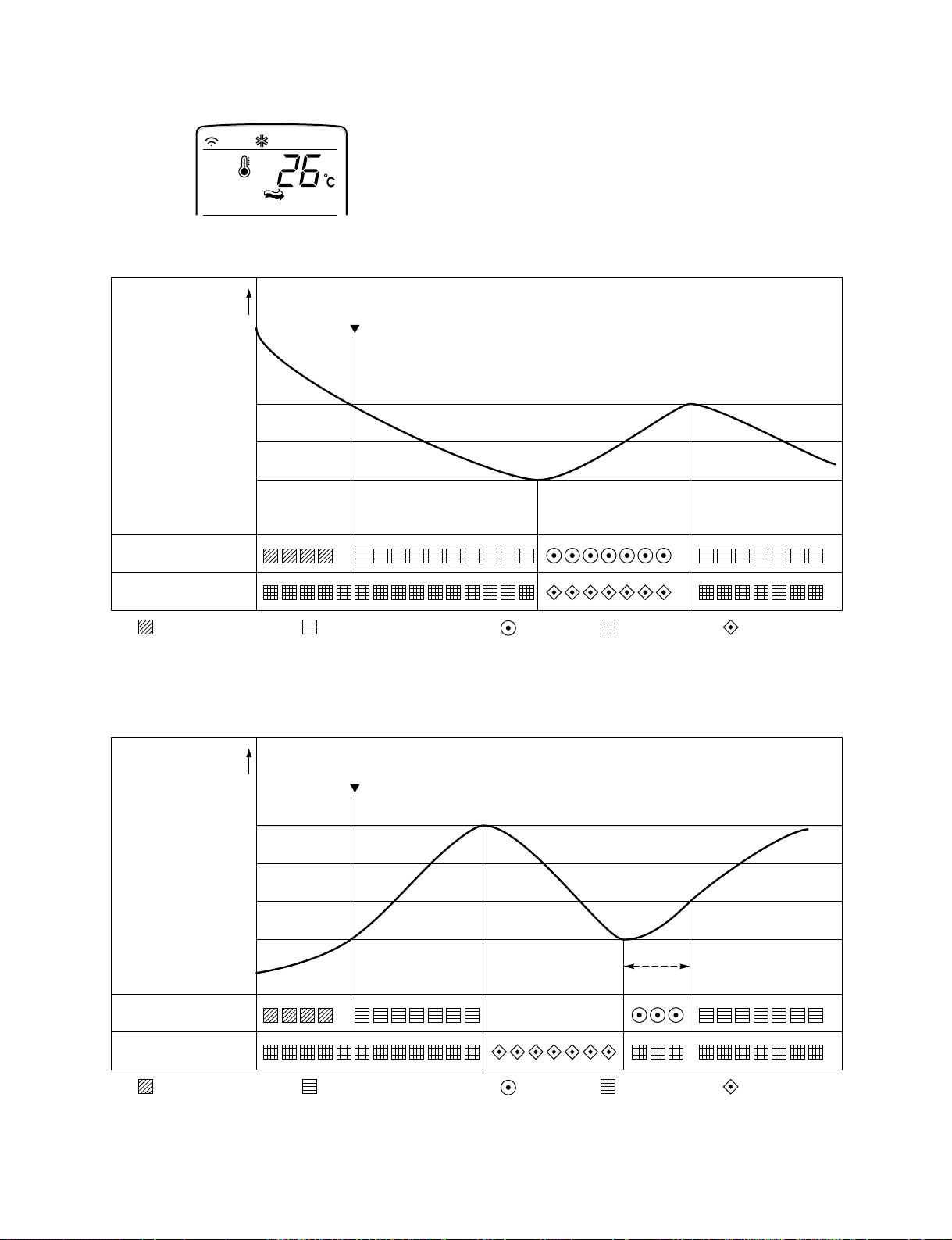
6. Natural wind by CHAOS logic
For more fresh feeling than other fan speed mode, press
the indoor fan Speed Selector and set to CHAOS mode.
In this mode, the wind blows like natural breeze by automatically changing fan speed according to the CHAOS
logic.
Intake Air temp.
OUTDOOR FAN/COMP.
INDOOR FAN
: Setting fan speed : LOW
Cooling on temp.
(Setting temp.+0.5)
Setting CHAOS Natural wind
Setting temp.
Cooling off temp.
(Setting temp.-0.5)
: CHAOS Natural wind
: COMP ON : COMP OFF
GRAPH of Natural wind by the CHAOS logis (During Cooling operation)
Intake Air temp.
30sec
OUTDOOR FAN/COMP.
INDOOR FAN
: Setting fan speed : LOW
Heating off temp.
(Setting temp.+3.0)
Setting CHAOS Natural wind
Heating on temp.
(Setting temp.)
: CHAOS Natural wind
: COMP ON : COMP OFF
GRAPH of Natural wind by the CHAOS logis (During Heating operation)
LOW OR STOP
 Loading...