

LG 9QK W1000NS User Manual

LSP-W1000_EVNT_ENG
Home Monitoring
System
Owner’s Manual
MODEL: LSP-W1000
- LSP-W1000NS
- LSP-W1000PS
- LSP-W1000AC
Before connecting, operating or adjusting this product,
please read this owner’s manual carefully and completely.
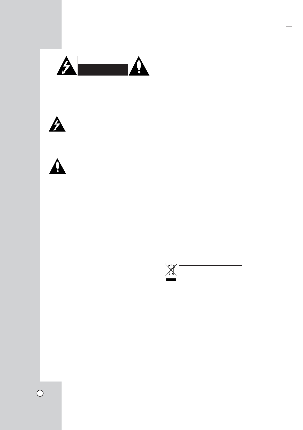
CAUTION
RISK OF ELECTRIC SHOCK
DO NOT OPEN
CAUTION: TO REDUCE THE RISK
OF ELECTRIC SHOCK
DO NOT REMOVE COVER (OR BACK)
NO USER-SERVICEABLE PARTS INSIDE
REFER SERVICING TO QUALIFIED SERVICE
This lightning flash with arrowhead symbol
within an equilateral triangle is intended to
alert the user to the presence of uninsulated dangerous voltage within the product’s
enclosure that may be of sufficient magnitude to constitute a risk of electric shock to
persons.
The exclamation point within an equilateral
triangle is intended to alert the user to the
presence of important operating and maintenance (servicing) instructions in the literature accompanying the product.
FCC WARNING: This equipment may generate or
use radio frequency energy. Changes or modifications to this equipment may cause harmful interference unless the modifications are expressly approved
in the instruction manual. The user could lose the
authority to operate this equipment if an unauthorized
change or modification is made.
REGULATORY INFORMATION: FCC Part 15
This equipment has been tested and found to comply with the limits for a Class B digital device, pursuant to Part 15 of the FCC Rules. These limits are
designed to provide reasonable protection against
harmful interference when the product is operated
in a residential installation. This product generates,
uses, and can radiate radio frequency energy and,
if not installed and used in accordance with the
instruction manual, may cause harmful interference
to radio communications. However, there is no guarantee that interference will not occur in a particular
installation. If this product does cause harmful interference to radio or television reception, which can
be determined by turning the product off and on, the
user is encouraged to try to correct the interference
by one or more of the following measures:
• Reorient or relocate the receiving antenna.
• Increase the separation between the product
and receiver.
• Connect the product into an outlet on a circuit
different from that to which the receiver is connected.
PERSONNEL.
• Consult the dealer or an experienced radio/TV
technician for help.
- Labelling information:
This device complies with Part 15 of the FCC rules.
Operation is subject to the following two conditions:
(1) This device may not cause harmful interference,
and (2) This device must accept any interference
received, including interference that may cause
undesired operation.
- RF Exposure Statement:
The antenna(s) used for this transmitter must be
installed to provide a separation distance of at least
20 cm from all persons and must not be colocated
or operating in conjunction with any antenna or
transmitter other than those contained in this device.
FCC Regulations Part 15 Declaration of
Conformity (DoC)
LG Corporation declares that the equipment
described in this document is within the requirements of the Code of Federal Regulations listed
below:
Title 47 Part 15, Subpart B, Class B for a digital
device.
This declaration is based upon the compliance of
the data transceiver to the above standards. LG has
determined that the models listed have been shown
to comply with the applicable technical standards if
no unauthorized change is made in the equipment
and if the equipment is properly maintained and
operated.
Apparatus shall not be exposed to dripping or
splashing and no objects filled with liquids, such as
vases, shall be placed on the apparatus.
Disposal of your old appliance
1. When this crossed-out wheeled bin symbol is
attached to a product it means the product is
covered by the European Directive 2002/96/
EC.
2. All electrical and electronic products should
be disposed of separately from the municipal
waste stream via designated collection facilities appointed by the government or the local
authorities.
3. The correct disposal of your old appliance will
help prevent potential negative consequences for the environment and human health.
4. For more detailed information about disposal
of your old appliance, please contact your
city office, waste disposal service or the shop
where you purchased the product.
2

Canada Notice
This Class B digital apparatus complies with
Canadian ICES-003, Issue 2, and RSS-210,
Issue 4 (Dec. 2000).
European Union
“To prevent radio interference to the licensed service, this
device is intended to be operated indoors and away from
windows to provide maximum shielding. Equipment (or its
transmit antenna) that is installed outdoors is subject to
licensing.”
Cet appareil numérique de la classe B est conforme
à la norme NMB-003, No. 2, et CNR-210, No. 4 (Dec.
2000).
« Pour empêcher que cet appareil cause du brouillage
au service faisant l'objet d'une licence, il doit être
utilisé à l'intérieur et devrait être placé loin des
fenêtres afi n de fournir un écran de blindage maximal.
Si le matériel (ou son antenne d'émission) est installé
à l'extérieur, il doit faire l'objet d'une licence. »
Operation is subject to the following two conditions:
this device may not cause interference, and (2)
this device must accept any interference, including
interference that may cause undesired operation of
the device.
The term “IC:” before the certifi cation/registration
number only signifi es that the Industry Canada
technical specifi cations were met.
This device has been designed to operate with an
antenna having a maximum gain of 2 dB. Antenna
having a higher gain is strictly prohibited per
regulations of Industry Canada. The required antenna
impedance is 50 ohms.
To reduce potential radio interference to other users,
the antenna type and its gain should be so chosen
that the equivalent isotropically radiated power
(EIRP) is not more than that required for successful
communication.
(1999/5/EC)
Translated Statements of Compliance
[English]
This product follows the provisions of the European
Directive 1999/5/EC.
[Danish]
Dette produkt er i overensstemmelse med det
europæiske direktiv 1999/5/EC
[Dutch]
Dit product is in navolging van de bepalingen van
Europees Directief 1999/5/EC.
[Finnish]
Tämä tuote noudattaa EU-direktiivin 1999/5/EC
määräyksiä.
[French]
Ce produit est conforme aux exigences de la Directive
Européenne 1999/5/EC
[German]
Dieses Produkt entspricht den Bestimmungen der
Europäischen Richtlinie 1999/5/EC
[Greek]
Το προϊόν αυτό πληροί τις προβλέψεις της
Ευρωπαϊκής Οδηγίας 1999/5/ΕC.
[Icelandic]
Þessi vara stenst reglugerð Evrópska Efnahags
Bandalagsins númer 1999/5/EC
[Italian]
Questo prodotto è conforme alla Direttiva Europea
1999/5/EC.
[Norwegian]
Dette produktet er i henhold til bestemmelsene i det
europeiske direktivet 1999/5/EC.
[Portuguese]
Este produto cumpre com as normas da Diretiva
Européia 1999/5/EC.
[Spanish]
Este producto cumple con las normas del Directivo
Europeo 1999/5/EC.
[Swedish]
Denna produkt har tillverkats i enlighet med EGdirektiv 1999/5/EC.
3

France Notice
For Metropolitan departments 2.400 -2.4835 GHz for
indoor use.
Some areas of France have a restricted frequency
band.
There are few possibilities for outdoor use:
On private property or on the private property of public
persons, use is subject to a preliminary authorization
procedure by the Ministry of Defense, with maximum
authorized power of 100 mW in the 2446.5–2483.5
MHz band.
Use outdoors on public property is not permitted.
In the departments listed below, for the entire 2.4 GHz
band:
Maximum authorized power indoors is 100 mW
Maximum authorized power outdoors is 10 mW
There is partial restriction of the 2.4 GHz band
for outdoor/indoor in part of the 2.4 GHz band,
Departments in which the use of the 2400–2483.5
MHz band is permitted with an EIRP of less than 100
mW indoors and less than 10 mW outdoors:
Italia Notice
Outdoor use is prohibited.
EMC Notice
Products bearing the CE marking comply with
the R&TTE Directive (1999/5/EC), EMC Directive
(2004/108/EC) issued by the Commission of the
European Community. Compliance with these
directives implies conformity to the following
European Norms (in parentheses are the equivalent
international standards and regulations):
• EN 55022 (CISPR 22)—Electromagnetic
Interference
• EN55024 (IEC61000-4-2, 3, 4, 5, 6, 8, 11)—
Electromagnetic Immunity
• EN61000-3-2 (IEC61000-3-2)—Power Line
Harmonics
• EN61000-3-3 (IEC61000-3-3)—Power Line Flicker
• EN 300 328-2—Technical requirements for radio
equipment
• EN 301 489-1, -17—General EMC requirements
for radio equipment
4
IMPORTANT SAFETY INSTRUCTIONS
CAUTION:
This product has been designed and manufactured to assure personal safety. Improper use can result in electric shock or fire hazard. The safeguards incorporated in this product will protect you if you observe the following procedures for installation, use, and servicing.
This product does not contain any parts that can be repaired by the user.
DO NOT REMOVE THE CABINET COVER, OR YOU MAY BE EXPOSED TO DANGEROUS VOLTAGE.
REFER SERVICING TO QUALIFIED SERVICE PERSONNEL ONLY.
1. Read these instructions. - All these safety and
operating instructions should be read before the
product is operated.
2. Keep these instructions. - The safety, operating
and use instructions should be retained for future
reference.
3. Heed all warnings. - All warnings on the product
and in the operating instructions should be adhered
to.
4. Follow all instructions. - All operating and use
instructions should be followed.
5. Do not use this apparatus near water. - For
example: near a bath tub, wash bowl, kitchen sink,
laundry tub, in a wet basement; or near a swimming
pool; and other areas located near water.
6. Clean only with dry cloth. - Unplug this product
from the wall outlet before cleaning. Do not use
liquid cleaners.
7. Do not block any ventilation openings. Install
in accordance with the manufacturer's instructions. - Slots and openings in the cabinet are pro-
vided for ventilation and to ensure reliable operation
of the product and to protect it from over-heating.
The openings should never be blocked by placing
the product on a bed, sofa, rug or other similar surface. This product should not be placed in a builtin installation such as a bookcase or rack unless
proper ventilation is provided or the manufacturer’s
instructions have been adhered to.
8. Do not install near any heat sources such as
radiators, heat registers, stoves, or other apparatus (including amplifiers) that produce heat.
9. Do not defeat the safety purpose of the polarized or grounding-type plug. A polarized plug
has two blades with one wider than the other. A
grounding type plug has two blades and a third
grounding prong. The wide blade or the third
prong are provided for your safety. If the provided plug does not fit into your outlet, consult
an electrician for replacement of the obsolete
outlet.
PLEASE READ AND OBSERVE ALL WARNINGS AND INSTRUCTIONS IN THIS OWNER’S
MANUAL. AND THOSE MARKED ON THE PRODUCT. RETAIN THIS BOOKLET FOR FUTURE
REFERENCE.
10. Protect the power cord from being walked on
or pinched particularly at plugs, convenience
receptacles, and the point where they exit from
the apparatus.
11. Only use attachments/accessories specified
by the manufacturer.
12. Use only with the cart, stand, tripod, bracket,
or table specified by the manufacturer, or sold
with the apparatus. When a cart is used, use
caution when moving the cart/apparatus combination to avoid injury from tip-over.
13. Unplug this apparatus during lightning storms
or when unused for long periods of time.
14. Refer all servicing to qualified service personnel. Servicing is required when the apparatus
has been damaged in any way, such as powersupply cord or plug is damaged, liquid has
been spilled or objects have fallen into the
apparatus, the apparatus has been exposed to
rain or moisture, does not operate normally, or
has been dropped.
PROGRAM
ADDITIONAL
5

Contents
Introduction ......................................... 7
Features ...............................................................7
Notice Regarding Wireless Communications ..7
Netstation (Main unit) .........................................8
Front panel ......................................................8
Rear panel ......................................................8
Camera .................................................................9
Front panel ......................................................9
Accessories .........................................................9
Side panel .......................................................9
Rear panel ......................................................9
Remote Control .................................................10
Remote Control Operation ............................10
Connecting cameras ........................................11
Wired connection ..........................................11
Connect the camera with wirelessly .............11
Connecting the Display device .......................11
Video connection ..........................................11
Hookup and Settings ....................... 11
VGA connection ............................................12
Connecting the audio device ...........................12
Connecting the USB device .............................12
Connecting to the network ..............................13
Connecting the power source .........................13
System operation ..............................................14
General explanation of the Live Screen .........15
Viewing System Information ..........................16
Viewing the System Log List ..........................16
Lock function ....................................................16
Menu configuration ..........................................17
General settings ................................................17
Camera settings ................................................17
Information ....................................................17
Record settings .................................................18
Target Media .................................................18
Rec. setting ...................................................19
Display settings ................................................19
Language ......................................................19
Dwell Time ....................................................19
Network settings ...............................................20
WAN Port ......................................................20
DDNS (Dynamic Domain Name System) .....20
Sender Mail ...................................................21
Receiver Mail ................................................21
Notification ...................................................21
Wireless .......................................................22
System Settings ................................................22
Clock .............................................................22
User Password ..............................................22
Recording .......................................... 24
Instant recording ..............................................24
PC requirements ...............................................26
Recommended PC requirements ..................26
Using the Web Viewer ......................................28
AP (Access Point) settings ..............................28
Status ............................................................28
WAN Port Configuration ................................29
Access Control ..............................................29
Denial of Service Setting ..............................30
Port Forwarding ............................................30
Special Application ........................................30
Config File .....................................................31
System Log ...................................................31
IP Filtering .....................................................32
MAC Filtering ................................................32
URL Filtering .................................................32
Upgrade Firmware ........................................33
Reference ......................................... 34
Troubleshooting ...............................................34
Recommended devices ....................................37
Supported external USB device list ..............37
The necessary Capacity for 1Hour
recording (Approximatly) .........................37
Factory default configuration settings ...........38
Specifications ...................................................40
6

Introduction
Features
• Simply connect the LSP-W1000 to your network cameras (sold separately) and to your TV or monitor, and
you'll be able to view camera images conveniently on your TV or monitor.
The LG Wireless cameras can be connected as well, that is you won't have to worry about running cables
from the LSP-W1000 to each camera.
• Use the Pan/Tilt function, aim the camera wherever you want by simply pressing the navigator keys on the
included remote control.
• The camera's built-in sensor detects motion by people or animals moving within the sensor's range. When
the sensor detects motion, the LSP-W1000 can alert you by sounding its built-in buzzer.
• Simply insert an optional USB memory stick or USB type external HDD device and you'll be able to record
movies of your camera images. Later you can use the remote control to play back movies on your TV or
monitor that were recorded by the LSP-W1000.
• Simply press the camera's PRIVACY button to hide the camera's lens when you don't want camera images
to be seen.
• Up to 4 cameras can be connected, allowing you to keep an eye on every room with just 1 LSP-W1000.
• When multiple cameras are registered, you can view up to 4 camera images at once and switch to monitor
a specific camera if necessary.
Notice Regarding Wireless Communications
1. To avoid wireless communication interference and instability, do not use this product near the following
devices.
• Wireless transmitters (radio transmitters, cellular transmitters, etc.)
• Wireless devices which operate at 2.4 GHz (security equipment, POS systems, cordless telephones,
etc.)
• Microwave ovens.
2. Wireless communication range and quality may be affected if the following types of objects are located
between or near this product and other wireless devices connected to this product. In the event that images
do not refresh at a regular rate, become cut off, etc., relocate this product, the other wireless devices, or
the obstacles (if possible) for more stable wireless communications.
• Metal door shutters
• Walls made of concrete, stone, or brick, or walls which contain aluminiumbased heat insulation
• Multiple walls
• Fire doors and glass
• Steel racks or shelves
3. Place cameras and this product at least 2 m (6.5 ft.) away from radios. Do not connect cameras and this
product to a power outlet used by a radio.
4. In case of low picture quality when you use the wireless mode.
• Change the channel of wireless option in the setup menu.
• Set the wireless band option to 11G.
• If you use a Notebook computer via the NetStation, it may cause the bad effect to the camera perfor-
mance.
IntroductionHookup and
Settings
RecordingSearch and
Playback
Client
Program
Reference
7
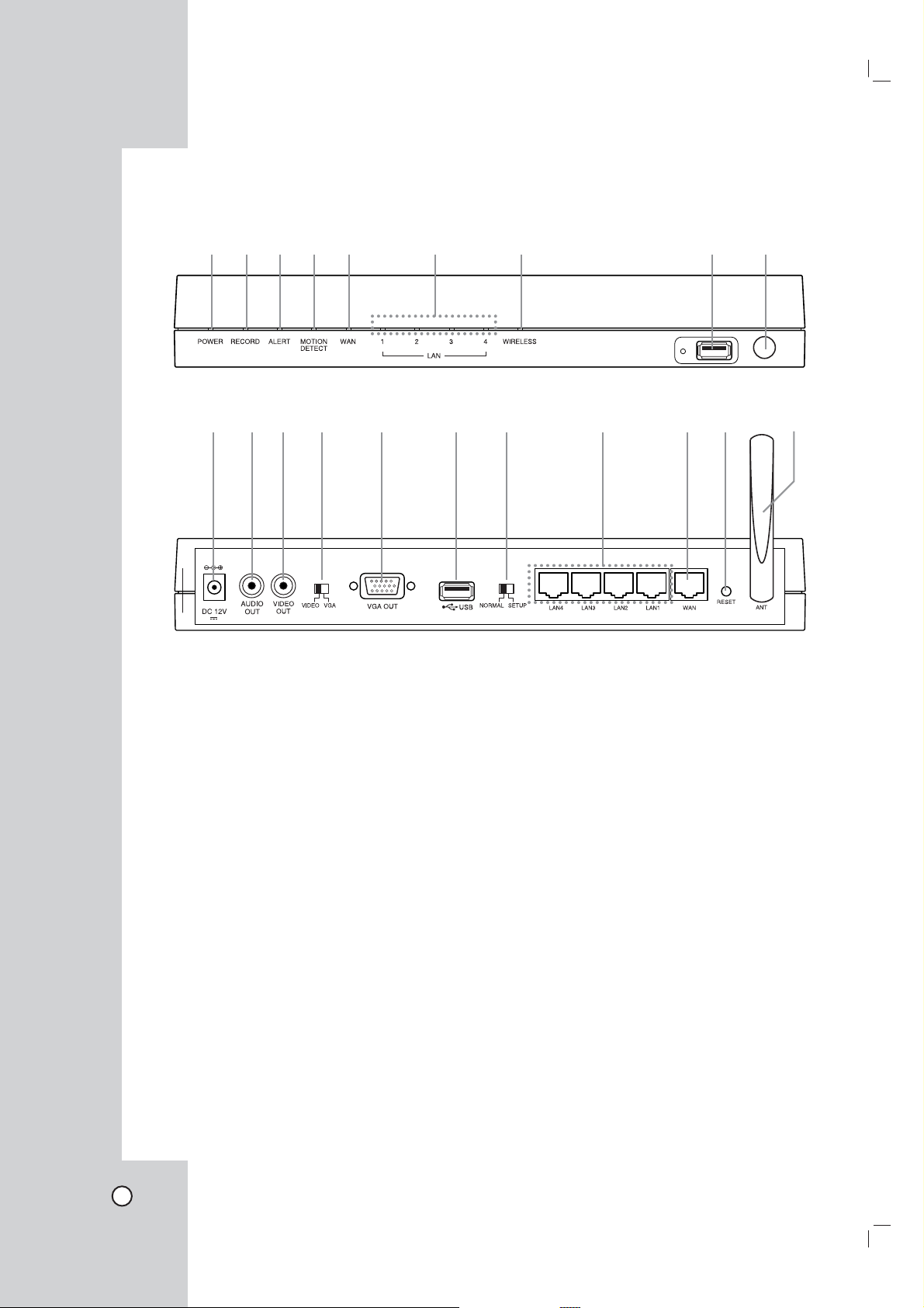
Netstation (Main unit)
Front panel
abc de f g h i
Rear panel
jklm n o p q rs t
a POWER indicator
Lights when the unit is turned on.
b RECORD indicator
Lights when recording is in progress.
c ALERT indicator
Lights when the camera is disconnected or the
system log will not be able to be saved.
d MOTION DETECT indicator
Blinks when a motion is detected.
e WAN indicator
Blinks when a network is connected.
f LAN (1-4) indicators
Fast blinking when the unit is connected to
cameras with LAN cable.
g WIRELESS indicator
Fast blinking when the wireless camera is in
progress.
h USB port
Connect an USB memory stick or USB type
external HDD device for recording or playback.
i Remote Sensor
Point the remote control here.
j DC 12 V power input jack (Class 2 Only).
k AUDIO OUT
Connect the audio input signal of an external
device.
l VIDEO OUT
Connect to a monitor or display device.
m VIDEO/VGA select switch
Video or VGA output mode select switch.
n VGA OUT
Connect a VGA monitor.
o USB port
Connect an USB memory stick or USB type
external HDD device for recording or playback.
p NORMAL/SETUP select switch
Mode select switch. Set the NORMAL mode
to activate this unit. The SETUP mode is used
only for service.
q LAN (1-4) ports
Connect the cameras with straight cable.
r WAN port
Connect the ethernet 10/100Mbps network
cable for controlling this unit via a PC network.
s RESET button
Pushing the button resets the unit using a pointed object. If you need to factory reset, pushing
the button for more 3 seconds and then the unit
will be rebooted automatically.
t Wireless Antenna
8
Camera
Front panel Side panel Rear panel
IntroductionHookup and
abc de fg
a MIC
The microphone is incorporated into the camera.
b STATUS indicator
Displays the camera status.
c PRIVACY button
Set the privacy mode, it allows you to make
sure images from the camera cannot be seen.
d Connection mode select switch
Wired or Wireless mode select switch.
Accessories
AC
adaptor
e Reset button
Resets camera.
f LAN port
Connects with LAN port of main unit by using
the Straight Cable.
g DC 12V power input jack (Class 2 Only)
NetStation
Wiress
Antenna
Remote
Control
Settings
RecordingSearch and
Playback
AC cord
NetStation
Stand
Audio/Video
cable
Lan Cable
AAA Type
Battery
Note: The accessories may be
different depending on models.
Client
Program
Reference
9
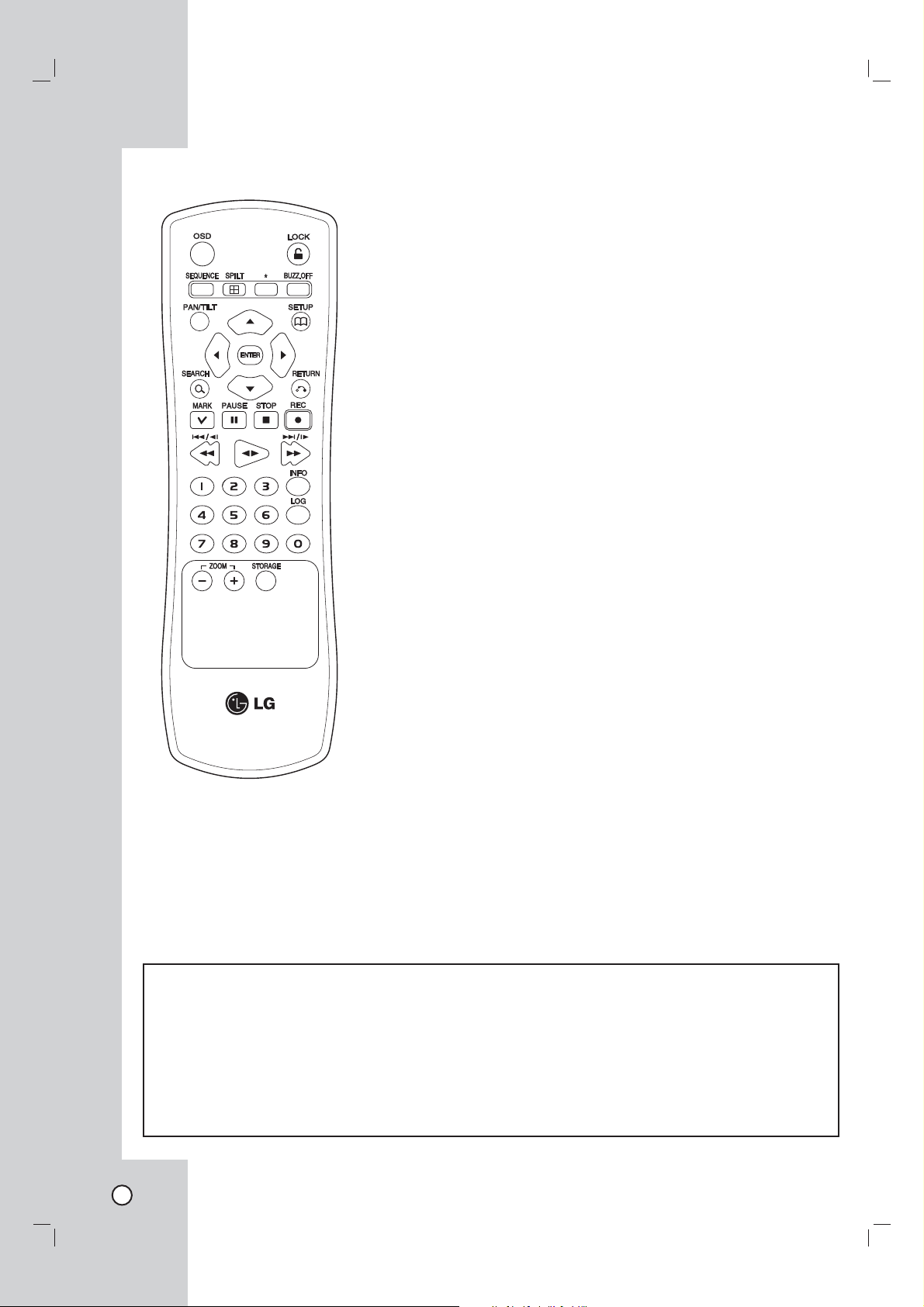
Remote Control
OSD
Accesses or removes the Onscreen Display.
LOCK
Displays the lock menu to change
user type or disable system
operation.
SEQUENCE
View all channels in sequence on
the full screen mode.
SPLIT
Displays the screen mode to full
or 4 screens.
BUZZ.OFF
Cancels alarm activation and
returns the system to the condition
before the alarm was activated.
PAN/TILT
Switches the unit to PAN/TILT
mode to control the connected
camera.
SETUP
Displays the setup menu or cancels operation of the setup menu.
Arrow Buttons (b B v V)
Selects or moves between the
menu options.
ENTER
Confirms menu selections.
SEARCH
Displays the search menu.
RETURN
Returns to the previous menu or
level.
MARK
Makes the mark point. Use this
button to move the registed camera position.
PAUSE (X)
Pauses playback.
STOP(x)
Stops playback or recording.
REC (z)
Starts recording.
m/c/.
Searches the recorded images
in reverse or skips the recorded
images.
bB
Playback or reverse playback of
recorded images.
M/C/>
Forward searches the recorded
images or skips the recorded
images.
Number Buttons (0,1-9)
Selects a channel directly or use
for network settings.
INFO
Displays the system information
window.
LOG
Displays the System Log List window.
ZOOM + / -
Zooms in/out on live images.
STORAGE
Displays the Taget Media Space
Information window.
*: This buttons are not available
for this unit.
Remote Control Operation
Point the remote control at the remote sensor and press the buttons.
Cautions:
• Do not mix old and new batteries and never mix different types of batteries such as standard, alkaline, etc.
• Do not put the batteries in the place where young children can reach.
Remote Control Battery installation
Detach the battery cover on the rear of the remote control, and insert two batteries (size AAA) with 3 and #
aligned correctly.
10
Hookup and Settings
Precautions
Be sure to switch off the camera before
installation and connection.
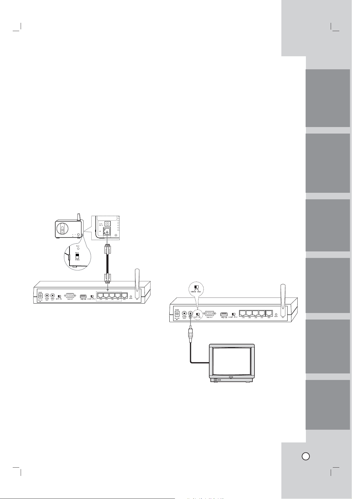
Connecting cameras
Up to 4 cameras can be connected to the Netstation.
You will need to configure the camera registration
settings for cameras connected to the Netstation.
(See page ??).
Wired connection
Set the Camera Mode Select switch to Wired position. Connect the LAN cabel as shown below. Turn
the Netstation and the camera power on.
The camera will be panning and tilting operation.
Rear of
camera
Connect the camera with wirelessly
If you want to connect without wires, following the
next stpes.
1. Set the camera mode select switch to Wireless
position.
2. Pushing the reset button to reset the camera
using a pointed object.
The camera will be panning and tilting operation.
Note:
The wireless function is possible after configuring the
camera registration settings for cameras connected
to this unit. (See page 17).
Connecting the Display device
Make one of the following connections, depending on
the capabilities of your existing equipment.
Video connection
When using the VIDEO OUT jacks, set the Video
Output mode select switch to VIDEO. Connect the
VIDEO OUT jacks on the rear of the Netstation to the
corresponding input jacks on the TV or monitor using
an VIDEO cable.
IntroductionHookup and
Settings
RecordingSearch and
Notes:
• If the camera is not connected to the Netstation
with LAN cable, the panning and tilting operation
is not be activated even if the camera is powered
on condition.
Before connection, set the camera Connection Mode
Select switch to Wired position.
• If you connect or registrer the camera to the
Netstation using the LAN cable, you should use
the supplied LAN cable or STP cable for shield
the electromagnetic interference.
• The camera(s) is(are) will be used after configuring the camera registration settings. (See page
17).
Playback
Client
Program
Note:
If the OSD is displayed too brightly, the OSD may
be shown like flickering on the monitor. In that case,
adjust the brightness.
Reference
11
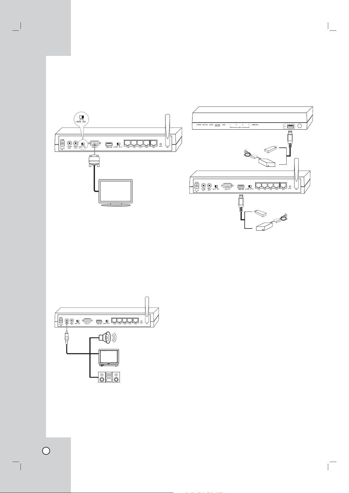
VGA connection
When using the VGA OUT jack, set the Video Output
mode select switch to VGA.
Connect the VGA OUT jacks on the rear of the
NetStation to the corresponding input jacks on the TV
or monitor using an VGA cable.
Note:
If the picture position is unbalanced on the VGA monitor, refer to the owner's manual of the VGA monitor
to adjust the picture position of the VGA monitor.
Connecting the USB device
Connect the USB memory stick or external USB HDD
device for recording or playing. Then, you should use
the recommened USB devices. (see page ??)
Connecting the audio device
Connect the AUDIO OUT jacks on the unit to the
mono audio in jacks on your audio deivce.
12
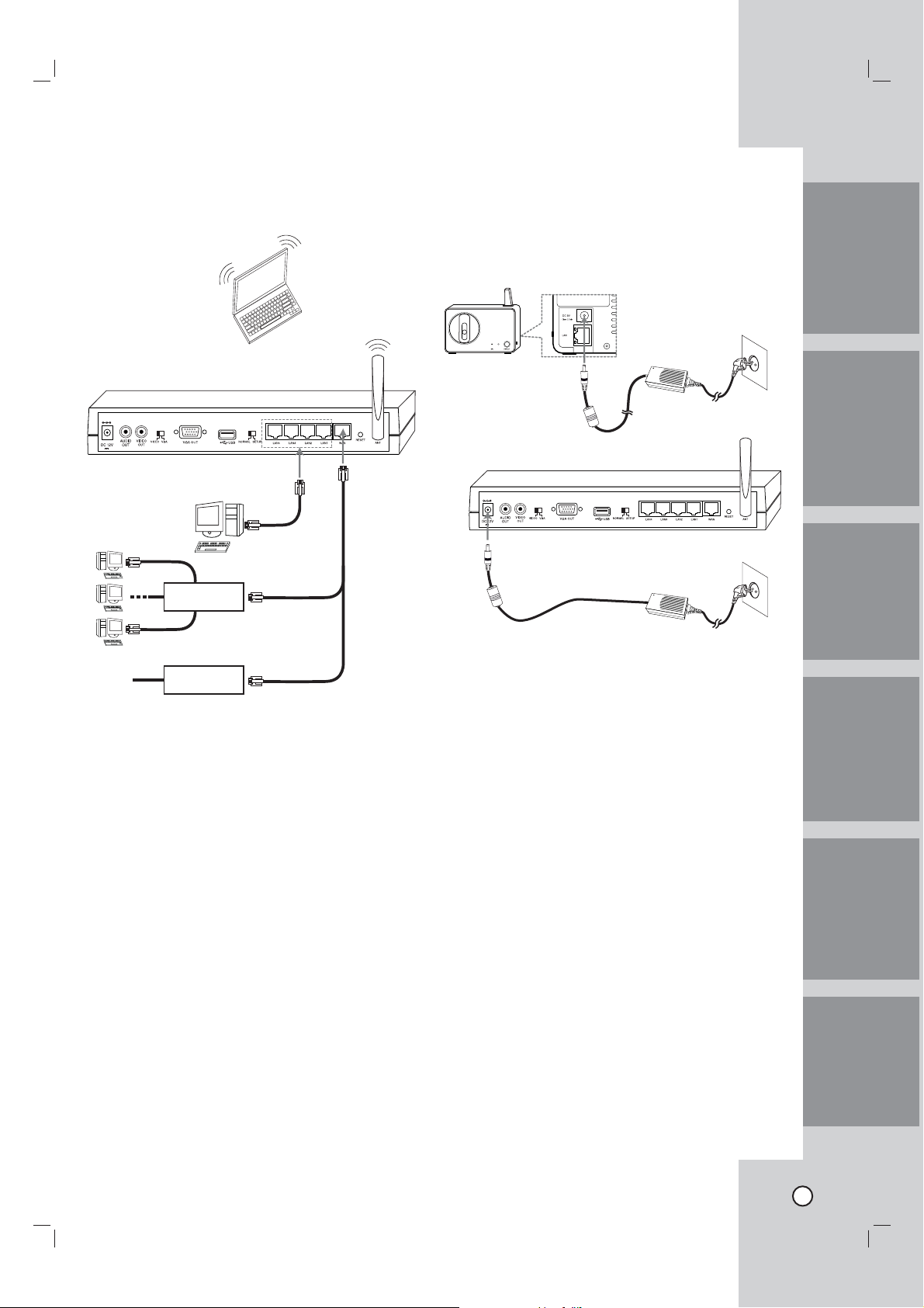
Connecting to the network
Connect the WAN port with a straight ethernet cable.
Router
Connecting the power source
Connect a DC 12 V power source to the DC 12 V
input terminal as shown below. When camera powered up, the camera performs a self-check (including
one panning and tilting operation).
IntroductionHookup and
Settings
RecordingSearch and
Modem
Notes:
• If you use the Router, you should set the Port
Forwarding.
• If the IP address of both Netstation and external
Router is same, the Netstation is not operate
normally. In this case, you should change the IP
address of the Router to solve the problem.
Notes:
• Use the supplied adaptor to prevent malfunction.
• The panning and tilting operation activates only
when the camera is connected to the Netstation
with LAN cabel.
Playback
Client
Program
Reference
13
 Loading...