How it Works
Log In / Sign Up
Buy Points
How it Works
FAQ
Contact Us
Questions and Suggestions
Users
LG
Loading...
#
995FT
10
995FTPLUS
12
995U
99G
11
99G-CS991D-EP
99G-CS991E-EP
99T
3
9CM2315VD1
9CM2315VD2
9CM237CVD1
9GW9718502
9GW97185D3
2
9GW97185D6
9QKA20240
9QKA2920
9QK ACC97WKR
9QK ACC97WKT
9QK CU1511
9QK CX8703IB
9QK CX8753PB
9QK DMFB84 BM
9QK DMFR74
9QK DMMB0502LX
9QK DMMB8811C0
9QK DMMB8811C1
9QK DMPD221
9QK DMPD239
9QK DMPD251
9QK DMPWMN5275
9QK DMR3
9QK DMRS3
9QK DMRS4
9QK DMWB1BH5
9QK DMWB1NP6
9QK DMWL1NB5
9QK DMWL1NB6
9QK DWAM82DB
9QKE00710
9QKE00711
9QKE40010
9QKE40110
9QKE40120
9QKE40210
9QKE40220
9QKE40230
9QKE40250
9QKE40310
9QKE40320
9QKE40330
9QKE40340
9QKE40410
9QKE40420
9QKE40430
9QKE40440
9QKE40450
9QKE40460
9QKE40510
9QKE40520
9QKE40530
9QKE40540
9QKE40610
9QKE40620
9QKE40630
9QKE40640
9QKE40650
9QKE40660
9QK F8010P
9QK-HB954W
9QK-HW904PA
9QK LAC9313SE
9QK LCF810
9QK LCF820
9QK LCS720
9QK-LGX11
9QK-LGX12
9QK LGX30
9QK LGX30G01
9QK LGX30G02
9QK-LN790
9QK LW130W
9QK M4MEDIA
9QK MAX620
9QK MB0402C0
9QK MB0402C1
9QK MB0402C2
9QK MB0502C0
9QK-N10
9QK-N41
9QK R2
9QK T2
9QK TWFMB008D
9QK TWFMK304D
9QK W1000NS
9QK W93 R
9QK W93 T
9QK W94R
9QK WN7111B
9QK WN7522C2
9QK-WN8522D2
9QK WT0601
Loading...
Loading...
Nothing found
9QK R2
User Manual
7 pgs
209.45 Kb
0
Table of contents
Loading...
LG 9QK R2 User Manual
...
LG User Manual
Download
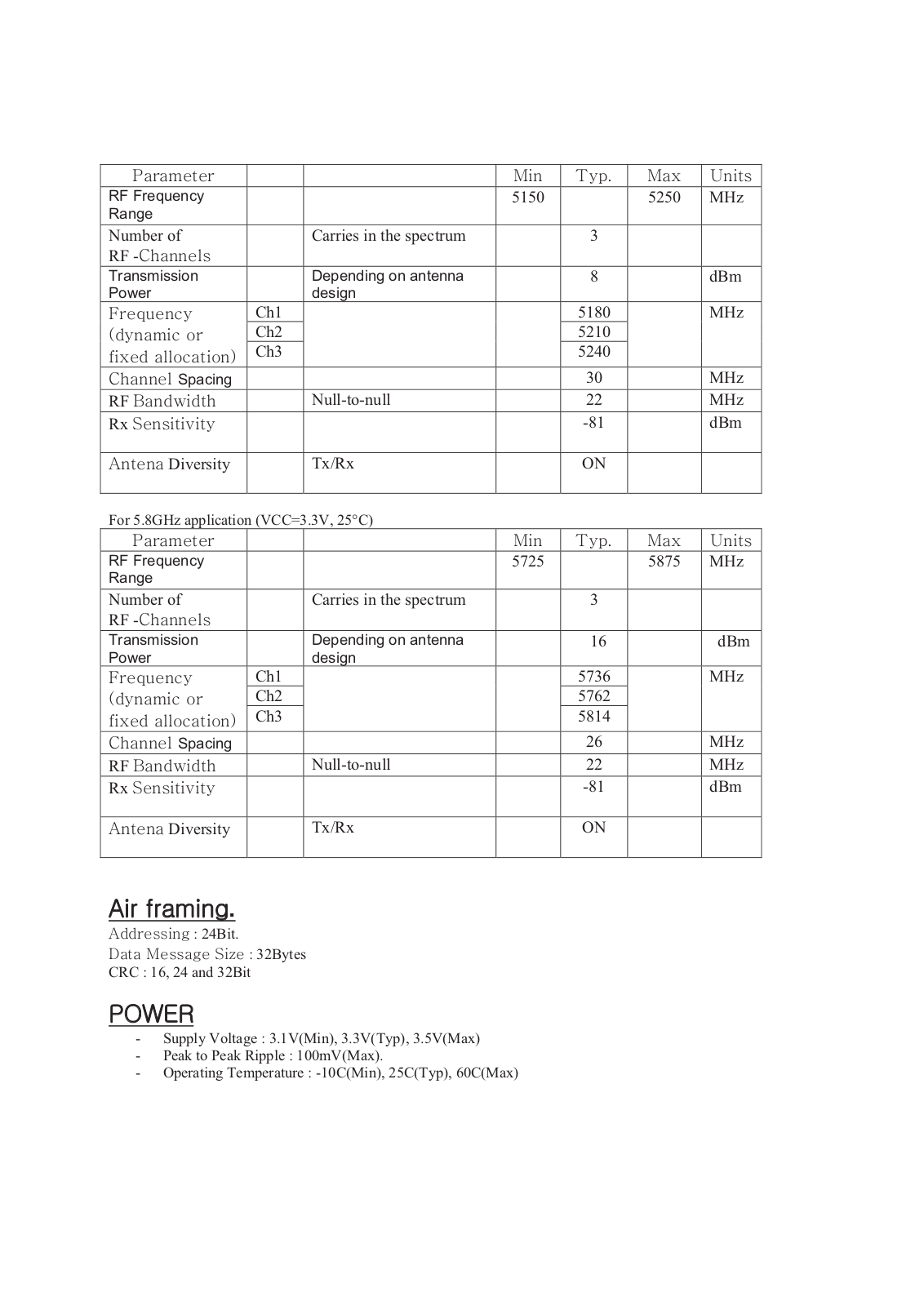
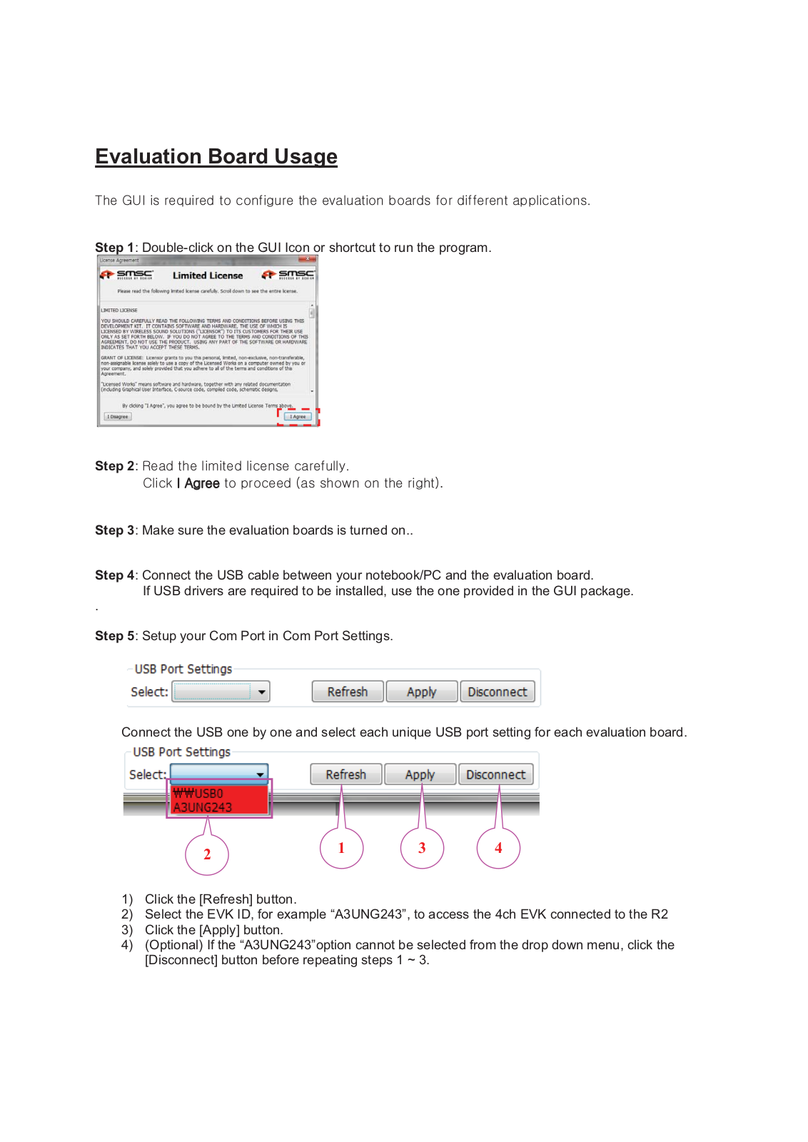
Specifications and Main Features
Frequently Asked Questions
User Manual
Download
Loading...
+
hidden pages
Unhide
You need points to download manuals.
1 point = 1 manual.
You can buy points or you can get point for every manual you upload.
Buy points
Upload your manuals
 Loading...