

LG 9QKE40110 Users manual

Before connecting, operating, or adjusting this product,
please read this instruction booklet carefully and completely.
VCR
OWNER’S MANUAL
MODEL: CC990M
Precautions
Information
2
Note to CATV system
installer: This reminder is
provided to call the CATV
system installer’s attention
to Section 820-40 of the
NEC which provides
guidelines for proper
grounding and, in
particular, specifies that
the cable ground shall be
connected to the
grounding system of the
building, as close to the
point of cable entry as
practical.
WARNING :TO REDUCE THE RISK OF FIRE OR ELECTRIC SHOCK,
DO NOT EXPOSE THIS APPLIANCE TO RAIN OR MOISTURE.
RISK OF ELECTRIC SHOCK
DO NOT OPEN
CAUTION
CAUTION : TO REDUCE THE RISK OF
ELECTRIC SHOCK,
DO NOT REMOVE COVER (OR BACK);
NO USER-SERVICEABLE PARTS INSIDE
REFER SERVICING TO QUALIFIED SERVICE PERSONNEL.
CAUTION : TO PREVENT ELECTRIC SHOCK, DO NOT USE THIS PLUG WITH AN EXTENSION CORD, RECEPTACLE OR
OTHER OUTLET UNLESS THE PLUG CAN BE FULLY INSERTED WITHOUT EXPOSING ANY PARTS OF THE BLADES.
This equipment has been tested and found to comply with the
limits for a Class B digital device, pursuant to Part 15 of the FCC
Rules. These limits are designed to provide reasonable protection
against harmful interference in a residential installation! This
equipment generates, uses and can radiate radio frequency
energy and, if not installed and used in accordance with the
instructions, may cause harmful interference to radio
communications.
However, there is no guarantee that interference will not occur in
a particular installation. If this equipment does cause harmful
interference to radio or television reception, which can be
determined by turning the equipment off and on, the user is
encouraged to try to correct the interference by one or more of
the following measures:
• Reorient or relocate the receiving antenna.
• Increase the separation between the equipment and receiver.
• Connect the equipment into an outlet on a circuit different from
that to which the receiver is connected.
• Consult the dealer or an experienced radio/TV technician for
help.
This Class (B) digital apparatus meets all requirements of the
Canadian Interference-Causing Equipment Regulations.
Cet appareil numérique de la classe (B) respecte toutes les
exigences du Règlement sur le matériel brouilleur du Canada.
REGULATORY INFORMATION
This lightning flash with arrowhead symbol within an
equilateral triangle is intended to alert the user to the
presence of uninsulated dangerous voltage within
the product’s enclosure that may be of sufficient
magnitude to constitute a risk of electric shock to
persons.
The exclamation point within an equilateral triangle is
intended to alert the user to the presence of
important operating and maintenance (servicing)
instructions in the literature accompanying the
product.
FCC WARNING: This equipment may generate or use radio frequency energy. Changes or modifications to this equipment
may cause harmful interference unless the modifications are expressly approved in the instruction manual. The user could lose
the authority to operate this equipment if an unauthorized change or modification is made.
Table of Contents
Features
3
• MTS Hi-Fi Stereo
•
OPR (Optimum Picture Response)
• Easy Graphic Menu
• Video Doctor
(Advanced Self-Diagnosis)
• 181 Channel Frequency
Synthesized Cable Compatible
Tuner with Autochannel
Programming and Multichannel
Scan
• 1 Year/7 Event Timer with DAILY
and WEEKLY Function
• Auto Power and Playback
Functions
• ITR (Instant Timer Recording)
• Real-Time Tape Counter
• Visual Search, Logic Search,
CM Skip
• Clean Still, Slow, Frame Advance
• Auto Tracking Function/
Auto Head Cleaner
• On-screen Display of Function
• Trilingual On-screen
Programming
(English/Spanish/Portuguese)
Features/Contents . . . . . . . . . . . . . .3
Safety Tips . . . . . . . . . . . . . . . . . .4-5
Remote Control . . . . . . . . . . . . . . . .6
Your VCR’s Controls
(Front & Rear) . . . . . . . . . . . . . . . . .7
Connections . . . . . . . . . . . . . . . .8-9
VCR to TV & Antenna to VCR . .8
CATV to VCR . . . . . . . . . . . . . . .9
Display Window . . . . . . . . . . . . . . .10
On-screen Display (OSD) . . . . . . . .11
Setting the On-screen Display . . . .12
Setting the menu . . . . . . . . . . . . . .13
Language Select . . . . . . . . . . .13
Function OSD On/Off . . . . . . . .13
Setting the Clock . . . . . . . . . . .13
Tuning in TV Stations . . . . . . . . . . .14
How to Play Back a Tape . . . . .15-17
Normal Playback . . . . . . . . . . .15
Special Playback . . . . . . . . . . .16
The Others’ Playback . . . . . . . .17
How to Record . . . . . . . . . . . . .18-22
Normal Recording . . . . . . . . . .18
Instant Timer Recording . . . . . .19
Timer Recording . . . . . . . . .20-21
Dubbing and Editing . . . . . . . . .22
Hi-Fi Stereo System . . . . . . . . .23-24
MTS Broadcast . . . . . . . . . . . .23
Audio Output Selection . . . . . . .23
Broadcast type selection
for recording . . . . . . . . . . . . . . .24
SAP Recording . . . . . . . . . . . . .24
Real-Time Counter/
Counter Memory . . . . . . . . . . . . . .25
Other Functions . . . . . . . . . . . . . . .26
Video Doctor . . . . . . . . . . . . . .26
Operating Hints . . . . . . . . . . . .26
ez (easy) Operation . . . . . . . . .27
Troubleshooting . . . . . . . . . . . . . . .28
Specifications . . . . . . . . . . . . . . . .29
Main features of
this VCR
The serial number is found on
the back of this unit. This
number is unique to this unit
and not available to others.
You should record requested
information here and retain this
guide as a permanent record of
your purchase.
Model No.
Serial No.
SAFETY TIPS
4
1. Read Instructions
All the safety and operating
instructions should be read before the
product is operated.
2. Follow Instructions
All operating and use instructions
should be followed.
3. Retain Instructions
The safety and operating instructions
should be retained for future reference.
4. Heed Warnings
All warnings on the product and in the
operating instructions should be
adhered to.
5. Cleaning
Unplug this product from the wall outlet
before cleaning. Do not use liquid
cleaners or aerosol cleaners. Use a
damp cloth for cleaning.
6. Water and Moisture
Do not use this product near water –
for example, near a bath tub, wash
bowl, kitchen sink, or laundry tub, in a
wet basement, or near a swimming
pool.
7. Accessories
Do not place this product on an
unstable cart, stand, tripod, bracket, or
table. The product may fall, causing
serious injury to a child or adult, and
serious damage to the product. Use
only with a cart, stand, tripod, bracket,
or table recommended by the
manufacturer, or sold with the product.
Any mounting of the product should
follow the manufacturer’s instructions,
and should use a mounting accessory
recommended by the manufacturer.
8. Transporting Product
A product and cart
combination should be
moved with care. Quick
stops, excessive force,
and uneven surfaces
may cause the product
and cart combination to
overturn.
9. Attachments
Do not use attachments not
recommended by the product
manufacturer as they may cause
hazards.
10.Ventilation
Slots and openings in the cabinet are
provided for ventilation and to ensure
reliable operation of the product and
to protect it from overheating, and
these openings must not be blocked
or covered. The openings should
never be blocked by placing the
product on a bed, sofa, rug, or other
similar surface. This product should
not be placed in a built-in installation
such as a bookcase or rack unless
proper ventilation is provided or the
manufacturer’s instructions have been
adhered to.
11. Power Sources
This product should be operated only
from the type of power source
indicated on the marking label. If you
are not sure of the type of power
supply to your home, consult your
product dealer or local power
company. For products intended to
operate from battery power, or other
sources, refer to the operating
instructions.
12. Line-Cord Polarization
This product is equipped with a
polarized alternating-current line plug
(a plug having one blade wider than
the other). This plug will fit into the
power outlet only one way. This is a
safety feature. If you are unable to
insert the plug fully into the outlet, try
reversing the plug. If the plug should
still fail to fit, contact your electrician
to replace your obsolete outlet. Do not
defeat the safety purpose of the
polarized plug.
13. Power-Cord Protection
Power-supply cords should be routed
so that they are not likely to be walked
on or pinched by items placed upon or
against them, paying particular
attention to cords at plugs,
convenience receptacles, and the
point where they exit from the product.
Important safeguards for you and your new product
Your product has been manufactured and tested with your safety in mind. However, improper use can result in
potential electrical shock or fire hazards. To avoid defeating the safeguards that have been built into your new
product, please read and observe the following safety points when installing and using your new product, and
save them for future reference.
Observing the simple precautions discussed in this section of the operating guide can help you get many years of
enjoyment and safe operation that are built into your new product.
PORTABLE CART
WARNING
SAFETY TIPS
5
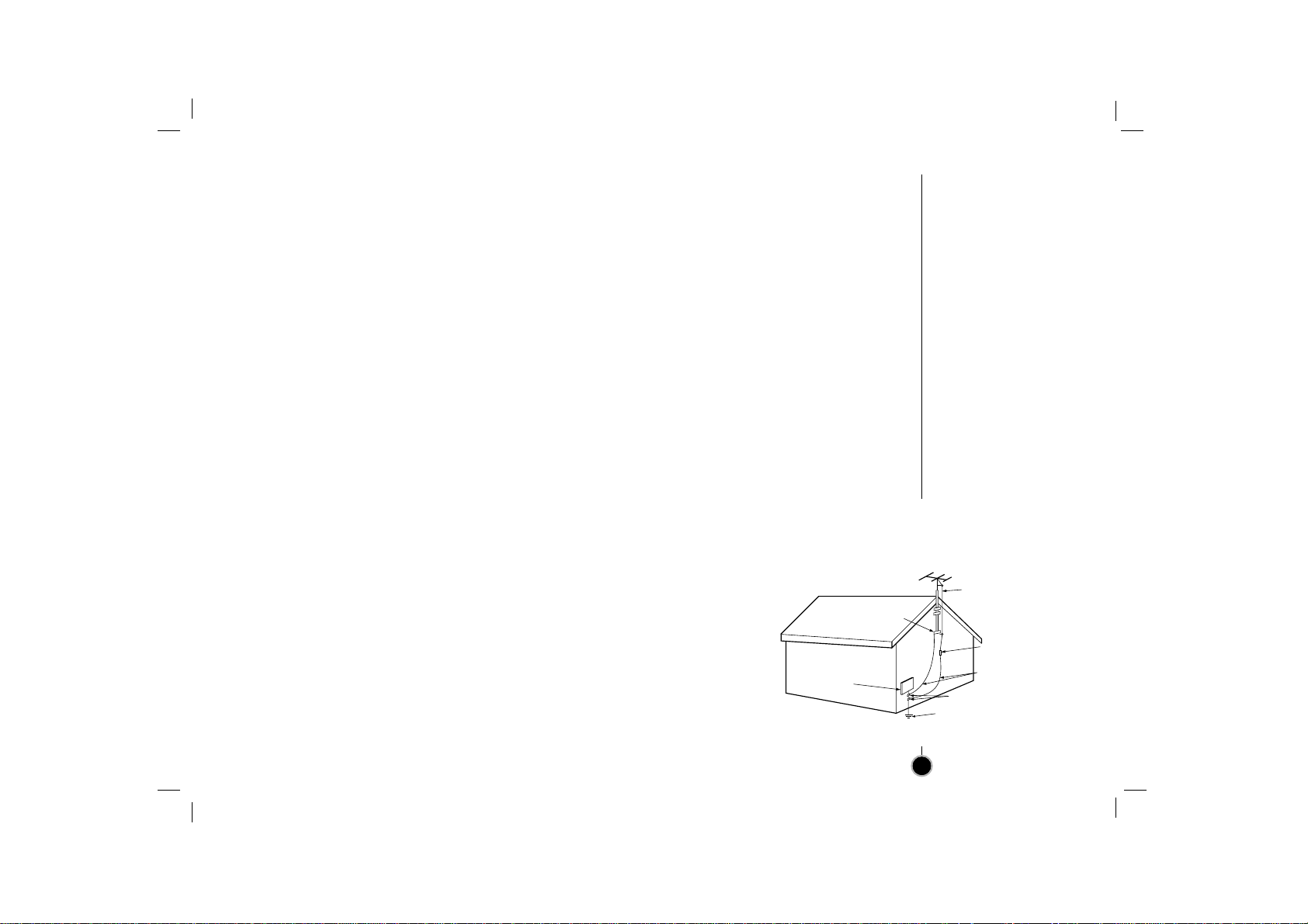
14.Outdoor Antenna Grounding
If an outside antenna or cable system
is connected to the product, be sure
the antenna or cable system is
grounded so as to provide some
protection against voltage surges and
built-up static charges. Article 810 of
the National Electrical Code (U.S.A),
ANSI/NFPA70 provides information
with regard to proper grounding of the
mast and supporting structure,
grounding of the lead-in wire to an
antenna discharge unit, size of
grounding conductors, location of
antenna-discharge unit, connection to
grounding electrodes, and
requirements for the grounding
electrode. (See figure 1 on the right.)
15.Lightning
For added protection for this product
(receiver) during a lightning storm, or
when it is left unattended and unused
for long periods of time, unplug it from
the wall outlet and disconnect the
antenna or cable system. This will
prevent damage to the product due to
lightning and power-line surges.
16. Power Lines
An outside antenna system should not
be located in the vicinity of overhead
power lines or other electric light or
power circuits, or where it can fall into
such power lines or circuits. When
installing an outside antenna system,
extreme care should be taken to keep
from touching such power lines or
circuits as contact with them might be
fatal.
17.Overloading
Do not overload wall outlets and
extension cords as this can result in a
risk of fire or electric shock.
18. Object and Liquid Entry
Never push objects of any kind into
this product through openings as they
may touch dangerous voltage points
or short-out parts that could result in a
fire or electric shock. Never spill liquid
of any kind on the product.
19.Servicing
Do not attempt to service this product
yourself as opening or removing
covers may expose you to dangerous
voltage or other hazards. Refer all
servicing to qualified service
personnel.
20. Damage Requiring Service
Unplug this product from the wall
outlet and refer servicing to qualified
service personnel under the following
conditions:
a. If the power-supply cord or plug is
damaged.
b. If liquid has been spilled, or objects
have fallen into the product.
c. If the product has been exposed to
rain or water.
d. If the product does not operate
normally by following the operating
instructions. Adjust only those
controls that are covered by the
operating instructions as an
improper adjustment of other
controls may result in damage and
will often require extensive work by
a qualified technician to restore the
product to its normal operation.
e. If the product has been dropped or
the cabinet has been damaged.
f. If the product exhibits a distinct
change in performance.
21. Replacement Parts
When replacement parts are required,
be sure the service technician has
used replacement parts specified by
the manufacturer or have the same
characteristics as the original part.
Unauthorized substitutions may result
in fire, electric shock, or other
hazards.
22. Safety Check
Upon completion of any service or
repairs to this product, ask the service
technician to perform safety checks to
determine that the product is in proper
operating condition.
23. Wall or Ceiling Mounting
The product should be mounted to a
wall or ceiling only as recommended
by the manufacturer.
24.Heat
The product should be situated away
from heat sources such as radiators,
heat registers, stoves, or other
products (including amplifiers) that
produce heat.
Figure 1
EXAMPLE OF GROUNDING ACCORDING TO
NATIONAL ELECTRICAL CODE INSTRUCTIONS
Electric Service
Equipment
NEC - NATIONAL ELECTRICAL CODE
Ground
Clamp
Antenna Lead in Wire
Antenna Discharge Unit
(NEC Section 810-20)
Grounding Conductors
(NEC Section 810-21)
Ground Clamps
Power Service Grounding
Electrode System
(NEC Art 250, Part H)
EJECT
CH+/TRK+
CH—/TRK—
CLEAR
ENTER
MENU
REC/
ITR
123
456
789
TV/VCR
SP/EP
SLOW
0
CM SKIP
POWER
ez POWER OFF
ez REPEAT
PLAY
P
/
S
T
I
L
L
S
T
O
P
FFREW
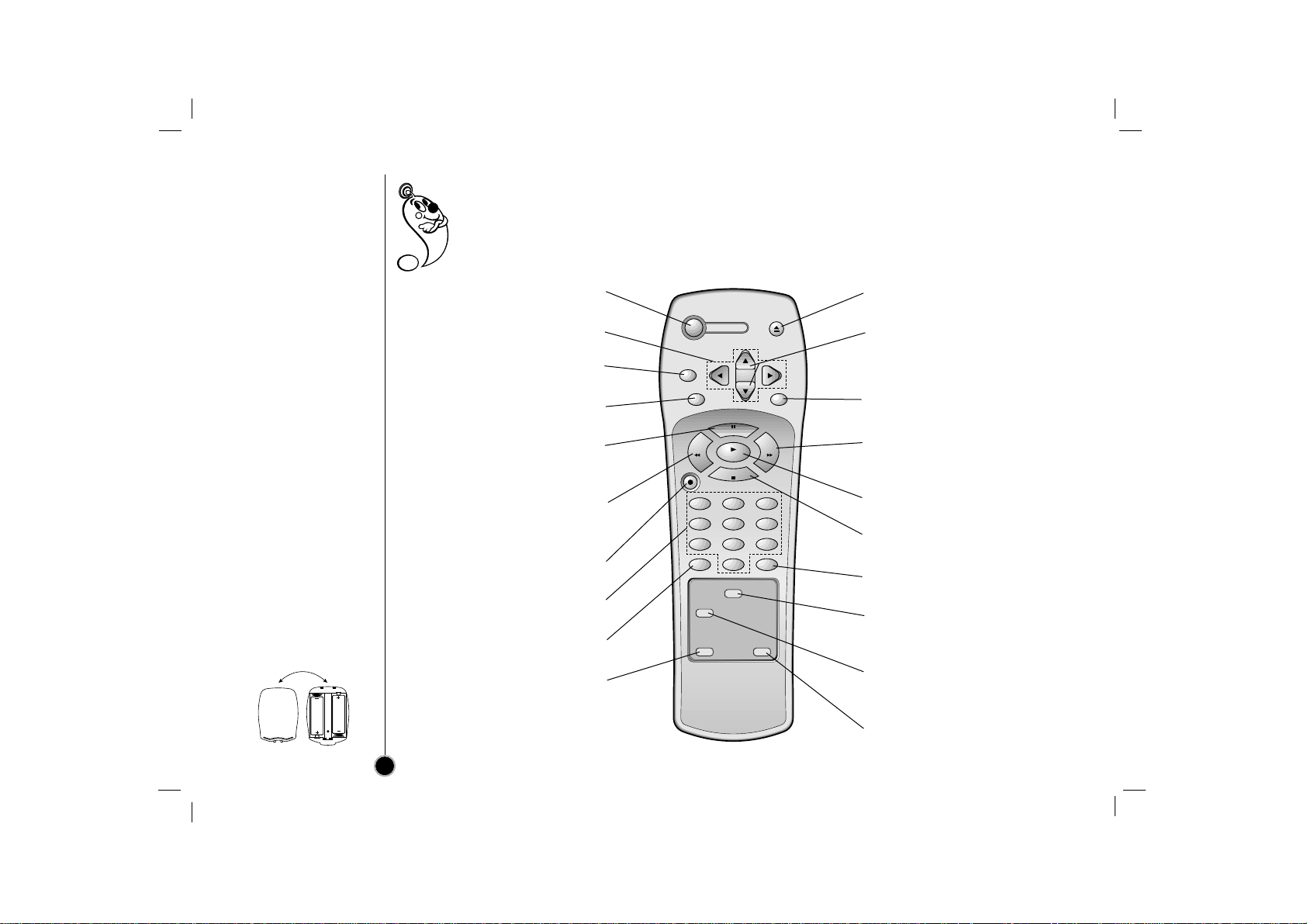
Remote Control
Location & Functions
6
Your video recorder (VCR) is designed so that almost all of it’s features can be controlled from the Remote
Control. Some features can also be controlled from the front panel of the video recorder. The
maximum operating distance that you may control your video recorder is about 25 feet (7.5 meters).
It must also be within an angle of 30 degrees either side of the remote sensor on the front of your
video recorder.
To avoid damage from possible battery leakage, remove the batteries if you do not plan to use the remote control
for an extended period of time. Do not use batteries of differing age or type. Always discard batteries safely.
To install batteries:
Your remote control is
powered by two AAtype
batteries.
1. To insert them, push the
tab backwards and lift
off the cover of the
remote control.
2. Put the two batteries
into the compartment
making sure the + and –
are correctly positioned.
3. Replace the cover.
POWER
To turn the VCR on and off.
DD EE FF GG
ARROWS
For OSD menu setting (page 12).
CLEAR
See the page 25.
ENTER
See the page 11, 12.
P/STILL
To still playback (page 16) or to
pause recording (page 18).
REW (Rewind)
To rewind the tape or for reverse
search (page 16).
REC (Record)/ITR
To start recording (page 18, 19)
NUMBER BUTTONS
To select a channel.
TV/VCR
See the page 18.
ez POWER OFF
See the page 27.
EJECT
To eject the tape in the VCR.
CHANNEL/TRACKING (+/–)
To scan up or down channels or
to obtain the best possible
picture (page 14, 15).
MENU
Shows main menu (page 12).
FF (Fast Forward)
To advance the tape or for
forward search (page 16).
PLAY
To play back a recorded tape.
STOP
To stop the tape.
CM SKIP
See the page 16.
SP/EP
Use to select recording speed
(page 18).
SLOW
For slow motion playback
(page 17).
ez REPEAT
See the page 27.
AA
AA
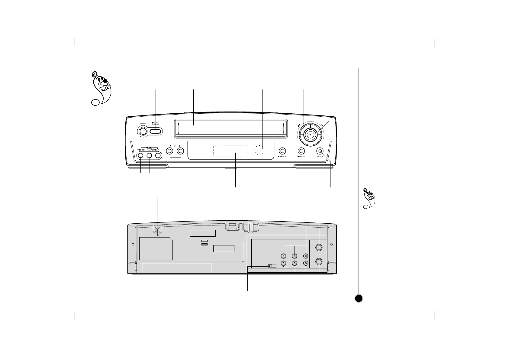
Each button on your VCR has the same function as it’s corresponding button on the remote control.
Your VCR’s
Controls
7
Power
(On/Off)
AUDIO IN Left/Right/
VIDEO IN jacks
(LINE2)
Remote
Control
sensor
Display
window
Channel
Selectors TV/VCR
PAUSE/
STILL
Fast
Forward
REC/ITR
(instant timer record)
Stop & Tape
Eject
Cassette
Compartment
Rewind
Play
You can select LINE1
(from AUDIO/
VIDEO IN jacks at
the rear) or LINE 2
(from AUDIO/ VIDEO IN
jacks at the front) pressing
CH (+/–) continuously to
display “LINE1” or “LINE2”
on the TV screen.
You can also select
“LINE1” or “LINE2” by
pressing 0 button twice or
four times.
VHF/UHF
/CATV
ANT.
IN
OUT
TO
TV
CH3 CH4
VIDEO
OUT
MONO
LINE1(AUX1)
IN
OUT
IN
R - AUDIO - L
Power cord
RF OUT CHANNEL Selector
Set this switch to channel 3 or 4.
AUDIO OUT Left/Right/
VIDEO OUT jacks
AUDIO IN Left/Right/
VIDEO IN jacks
(LINE1)
ANT.(Antenna)IN
(connect the
antenna using this
jack)
OUT TO TV
(connect to your TV
using this jack)
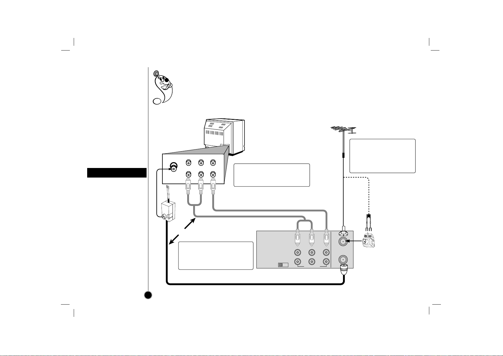
Connections
VCR to TV &
Antenna to VCR
The guidance given on the next two pages is the most common forms of connection. However please
check with your manufacturers instruction books for specific information. Make sure all connections
are made with both your VCR and additional appliance unplugged from the mains to avoid
damaging your equipment. Connecting a VCR using a Audio/Video cable is one of the best ways to
achieve optimum sound and picture quality from video-tape playback. If you own a stereo TV you will
be able to enjoy stereo sound when playing a stereo video tape or stereo TV reception.
When a TV is connected
with a coaxial cable only
When the TV is connected
to the OUT TO TV using a
supplied coaxial cable only,
set the channel selector at
the rear to CH 3 or CH 4,
not employed for
broadcasts, and select the
same channel on the TV.
When a TV is connected
with an audio/video cable
When the TV is connected
using an audio/video cable,
turn the TV and VCR on,
and select the video input
mode on the TV.
VCR reception setting
8
VHF/UHF
/CATV
ANT.
IN
OUT
TO
TV
CH3 CH4
VIDEO
OUT
MONO
LINE1(AUX1)
IN
OUT
IN
R - AUDIO - L
To OUT TO TV
VCR s Back Panel
TV set
Cable/
Antenna
R-AUDIO-L
VIDEO
IN
OUTINOUT
From
AUDIO/VIDEO OUT
To
AUDIO/VIDEO IN
AUDIO/VIDEO Cable
(Supplied)
75 ohm Coaxial Cable
with Antenna Adapter (supplied)
OR
75 ohm
Coaxial
Cable
300 ohm
twin lead
300/75 ohm
Adaptor
(Not supplied)
OR
VHF/UHF Antenna
2-2Audio/Video cable connection
improves the picture and
sound quality.
2-1Connect the supplied Coaxial
Cable to OUT TO TV on the
VCR and antenna connector
on your TV.
1 Disconnect the coaxial
cable (from antenna or
cable company) from your
TV and connect it to
ANT.IN on the VCR.
VHF/UHF
/CATV
ANT.
IN
OUT
TO
TV
CH3 CH4
VIDEO
OUT
MONO
LINE1(AUX1)
IN
OUT
IN
R - AUDIO - L
75 ohm
Cable
System
IN
OUT
CABLE CONVERTER
VCR’s Back Panel
75 ohm Coaxial Cable with
Antenna Adapter (supplied)
TV set
Cable/
Antenna
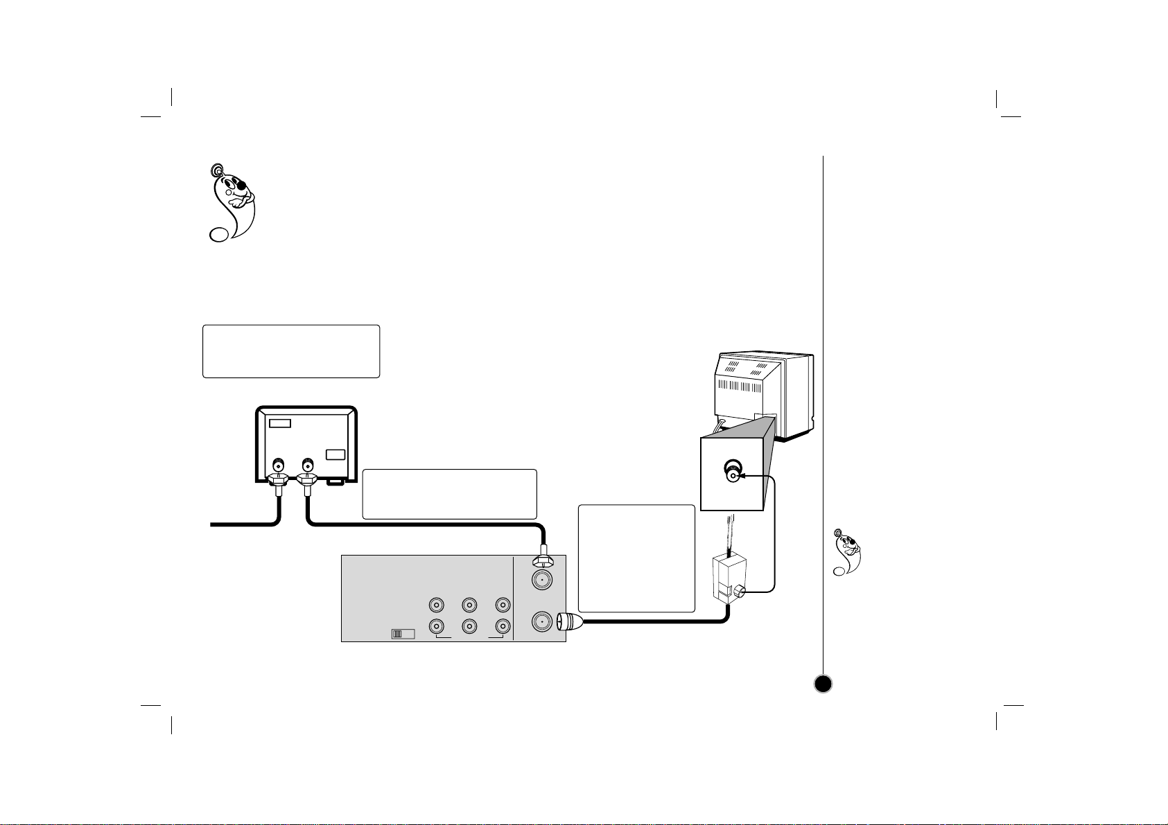
If your cable service supplies you with a cable converter box, you can use the basic connection shown
below.
To view or record CATV channel
1 Set the TV channel to the video output channel as located on the back of the VCR (CH3 or CH4).
2 Set the VCR channel selector to the output channel of the cable converter box by pressing
CH (+/–) or number buttons (0-9) of your VCR. (Example: CH3)
3 Select the channel to view at the Cable Converter Box.
Connections
CATV to VCR
9
With this connection,
you CANNOT
record one
program while
viewing another.
1Connect the cable from the
CATV system to the input on
the CATV converter.
2Connect the output on the
converter to ANT.IN on this
VCR.
3Connect the
supplied coaxial
cable to OUT TO
TV on the VCR
and antenna
connector on
your TV.
 Loading...