

DISASSEMBLY
- 9 -
(b)
(c)
(a)
(a)
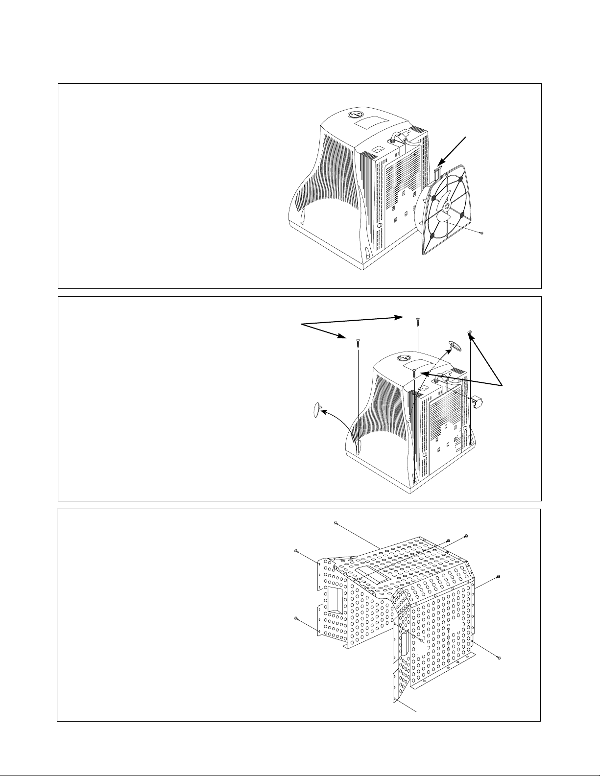
3. TOP SHIELD REMOVAL
1) Remove four screws (a).
2) Remove four screws (b).
3) Remove two screws (c).
5) Slide the Top Shield away from the monitor.
2. BACK COVER REMOVAL
1) Remove two screw covers (a).
2) Remove four screws (b) from the Back Cover.
3) Remove the Signal Cap (c).
4) Slide the Back Cover away from the Front
Cabinet of the monitor.
(b)
(b)
(a)
(a
(c)
(c)
(a)
(b)
(a)
(b)
(a)
1. TILT/SWIVEL REMOVAL
1) Set the monitor face downward.
2) Remove screw (a).
3) Pressing the latch (b), carefully remove
the Tilt/Swivel by pulling it upward.
(b)
- 10 -
5. VIDEO PCB ASSEMBLY & CONTROL PCB ASSEMBLY REMOVAL
1) Disconnect P301, P302, P3 from the Video PCB.
2) Remove the connect (a).
3) Remove the Video PCB Assembly from the main total Assembly.
4) Remove two screws (b).
5) Remove the Control PCB Ass’y.
Anode Cap
DY Pin
(to P701)
Purity
(to P454)
Purity
to P453)
Tilt & Convergence
(to P451)
Degaussing Coil
(to P901)
P451
P454
P401
P453
(a)
(a)
(a)
(b)
(b)
P402
Control PCB
(P201)
P702
P921
P901
P302
P301
(
4. TOTAL CHASSIS ASSEMBLY REMOVAL
1) Disconnect P901 (Degaussing pin),
P701 (DY pin), P451(Tilt & Convergence
pin), P453,P454 (Purity pin) , P401 CDT
Earth Pin from the Main PCB.
2) Disconnect the CDT Earth Pin’s(c) from
the Video PCB.
3) Carefully separate the CDT Board
Assembly from the CDT neck.
4) Discharge the remaining static
electricity by shorting between
the Anode Cap and the CDT ground.
5) Disconnect the Anode Cap
from the CDT.
6) Remove three screws (a).
7) Remove two screws (b).
8) Remove the Total Chassis Assembly
from the Cabinet.
(c)
(c)
P401
(b)
P201
(b)
P402
(a)
P3
P301
P302
P702
 Loading...