

LG 995FT, FB995C-UA-UP BLOCK DIAGRAM
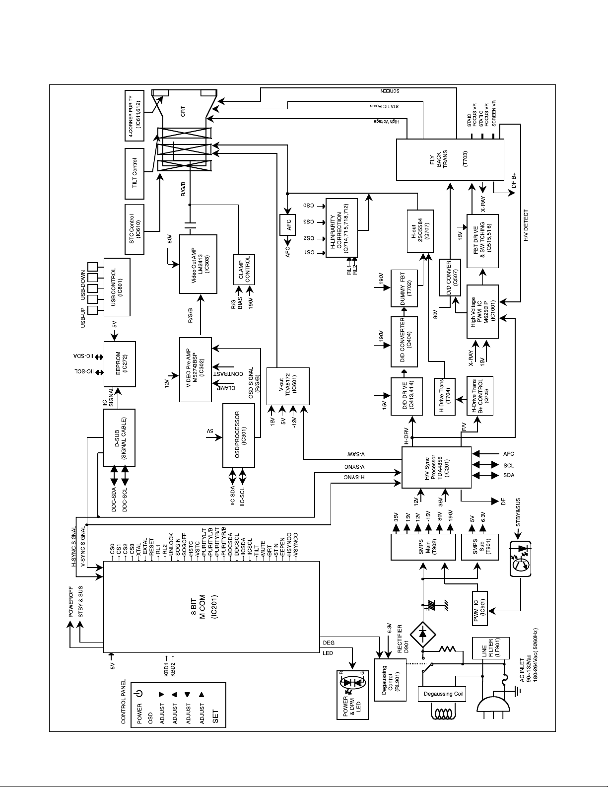
BLOCK DIAGRAM
- 14 -

DESCRIPTION OF BLOCK DIAGRAM
- 15 -
1. Line Filter & Associated Circuit
This is used for suppressing noise of power input line
flowing into the monitor and/or some noise generated in
this monitor flowing out through the power input line.
That is to say, this circuit prevents interference between
the monitor and other electric appliances.
2. Degauss Circuit & Coil
The Degauss circuit consists of the degaussing coil, the
PTC (Positive Temperature Coefficient) thermistor
(TH901), and the relay(RL901). This circuit eliminates
abnormal color of the screen automatically by
degaussing the slot mask in the CRT when turn on the
power switch. When you need to degauss while using
the monitor select DEGAUSS in the SPECIAL on the
OSD menu.
3. SMPS(Switching Mode Power Supply).
This circuit works with power of 90~132Vac/ 196~
264Vac (50/60Hz).
The operation procedure is as follows:
1) AC input voltage is rectified and smoothed by the bridge
diode (D901) and capacitors (C912).
2) The rectified voltage (DC voltage) is applied to the
primary coil of the transformer (T901,T902).
3) The control IC (IC901) generates switching pulse to turn
on and off the primary coil of the transformer (T902)
repeatedly.
4) Depending on the turn ratio of the transformer , the
secondary voltages appear at the secondary coil of the
transformer (T902).
5) These secondary voltages are rectified by each diode
(D922.923,924,926,925,933) and operate the other
circuits. (Deflection , Video Amplifier ,..... etc.).
The switching IC (IC901) controls input-pulse-width and
generates secondary voltages by sub-transformer
(T901).
4. Display Power Management Circuit.
This circuit control power consumption of the monitor by
detecting H and V sync signal.
There are Stand-by and suspend mode.
When no horizontal or vertical sync signal input, the
circuit consists of Q903 and IC913 becomes stand-by
and suspend mode. Its power consumption is below
8W.
5. X-ray Protection.
This circuit detects the rectified DC voltage comes from
the FBT pin 6. If the high volltage of the FBT reaches up
to about 30kV (abnormal state), high voltage control
PWM IC (IC1001) detects it. And PWM IC (IC1001)
prevent output voltage to the gate of switching FET
(Q507). It stops operating primary circuit of the FBT
(T703), and high voltage is not be generated.(In the
normal state, the high voltage is about 27kV.)
6. Micom (Microprocessor) Circuit.
The operating procedure of Micom (Microprocessor) and
its associated circuit is as follows:
1) H and V Sync signal is supplied from the D-sub to the
Micom (IC201).
2) The Micom (IC201) distinguishes polarity and frequency
of H and V sync.
3) The Micom controls each OSD function signals.(H-size,
H-position, V-size, etc.)
4) The controlled data of each mode is stored in itself. User
can adjust screen condition by each OSD function. The
data of the adjust screen condition is stored
automatically.
7. Horizontal and Vertical Synchronous Processor
This circuit generates the horizontal drive pulse and the
vertical drive pulse by taking sync-signal from the signal
cable. This circuit consists of the TDA4856 (IC701) and
the associated circuit.
8. Oscillating Circuit for D/D Converter.
This circuit generates the saw-tooth wave which has the
horizontal period by taking the output of the TDA4856
(IC701).
9. D/D (DC to DC) Converter.
This circuit supplies DC voltage to the horizontal
deflection output circuit by decreasing DC 190V which is
the secondary voltage of the SMPS in accordance with
the input horizontal sync signal.
10. Side-Pincushion Correcting Circuit.
This circuit improves the side-pincushion of the screen
by mixing east-west wave to the output of the horizontal
deflection D/D converter which is used for the supply
voltage source (B+) of the deflection circuit.
11. D/D Drive & Convert Circuit.
This circuit is used for supplying B+ voltage to horizontal
deflection output transistor(Q707). This circuit makes to
add side-pincushion correcting signal to B+ voltage.
12. Horizontal Deflection Output Circuit.
This circuit makes the horizontal deflection by supplying
the saw-tooth current to the horizontal deflection yoke.
13. High Voltage Output & FBT (Fly Back Transformer).
The high voltage output circuit is used for generating
pulse wave to the primary coil of the FBT (Fly Back
Transformer (T703)). A boosted voltage (about 27kV)
appears at the secondary of the FBT and it is supplied to
the anode of the CRT. And there are another output
voltages such as the dynamic focus frequency.
14. H-Linearity Correction Circuit.
This circuit corrects the horizontal linearity for each
horizontal sync frequency.
 Loading...