

LG 98LS95A-5B User manual

OWNER’S MANUAL
MONITOR SIGNAGE
Please read this manual carefully before operating the your set and retain it
for future reference.
MONITOR SIGNAGE MODELS
98LS95A
www.lg.com

TABLE OF CONTENTS
2
ENGLISH
TABLE OF CONTENTS
3 LICENSES
4 ASSEMBLY AND
PREPARATION
4 Accessories
6 Optional Accessories
7 Parts and Buttons
8 Connecting the Speakers
9 Connecting Wi-Fi Dongle
9 Connecting IR and Light Sensor
9 Portrait Layout
10 Connecting the Eye-Bolt Bracket
11 Attaching the Detachable Logo
12 How to Install the Guide Bracket
13 Installing on a Wall
14 REMOTE CONTROL
16 MAKING CONNECTIONS
16 Connecting to a PC
19 External Device Connection
20 Using the Input List
30 USER SETTINGS
30 Main Menu Settings
30 - Quick Settings
31 - Picture Setting
35 - Sound Settings
36 - Network Settings
39 - General Settings
40 Installing the LG Monitor Software
42 TROUBLESHOOTING
44 PRODUCT SPECIFICATIONS
49 IR CODES
51 TO CONTROL MULTIPLE
PRODUCTS
51 Connecting the cable
51 RS-232C Configurations
51 Communication Parameter
52 Command Reference List
54 Transmission/Reception Protocol
20 ENTERTAINMENT
20 Using My Media
20 - Connecting USB storage devices
22 - Files Supported by My Media
25 - Viewing Videos
26 - Viewing Photos
26 Information
26 File Manager
27 - Listening to Music
28 - Settings
29 Picture ID Settings
LICENSES
3
LICENSES
Supported licenses may differ by model. For more information of the licenses, visit www.lg.com.
The terms HDMI and HDMI High-Definition Multimedia Interface, and the
HDMI logo are trademarks or registered trademarks of HDMI Licensing LLC in
the United States and other countries.
This DivX Certified® device has passed rigorous testing to ensure it plays
DivX® video.
To play purchased DivX movies, first register your device at vod.divx.com.
Find your registration code in the DivX VOD section of your device setup
menu.
DivX Certified® to play DivX® video up to HD 1080p, including premium
content.
DivX®, DivX Certified® and associated logos are trademarks of DivX, LLC
and are used under license.
Covered by one or more of the following U.S. patents: 7,295,673; 7,460,668;
7,515,710; 7,519,274.
Manufactured under license from Dolby Laboratories. Dolby and the double-D
symbol are trademarks of Dolby Laboratories.
ENGLISH
For DTS patents, see http://patents.dts.com. Manufactured under license from
DTS Licensing Limited. DTS, the Symbol, & DTS and the Symbol together are
registered trademarks, and DTS 2.0+Digital Out is a trademark of DTS, Inc.
DTS, Inc. All Rights Reserved.
NOTE
• The warranty will not cover any damage caused by using the product in an excessively dusty
environment.
ASSEMBLY AND PREPARATION ASSEMBLY AND PREPARATION
4
ENGLISH
ASSEMBLY AND PREPARATION
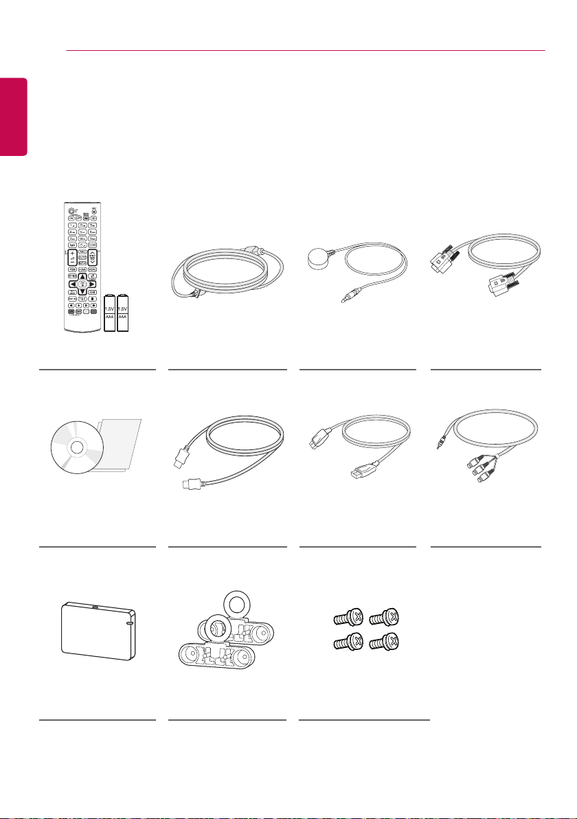
Accessories
Please check whether all the components are included in the box before using the product. If there are any
missing components, contact the retail store where you purchased the product. The illustrations in this manual
may differ from the actual product and accessories.
Remote Control,
Batteries (AAA) 2 EA Power Cord IR and Light Sensor RS-232C Cable
CD (Owner’s Manual)/
Card HDMI Cable DISPLAYPORT Cable
Wi-Fi Dongle
(AN-WF500)
Eye-Bolt Bracket
(2 EA)
Stereo to
COMPONENT
Gender
M4 x L12 Screws (4 EA)
(For Eye-Bolt Bracket)
CAUTION
• Always use genuine components to ensure safety and product performance.
• The product warranty will not cover damage or injury caused by the use of counterfeit components.
NOTE
• The accessories supplied with your product may vary depending upon the model.
• Product specifications or contents in this manual may be changed without prior notice due to
upgrade of product functions.
• SuperSign Software and Manual
- Downloading from the LG Electronics website.
- Visit the LG Electronics website (www.lgecommercial.com/supersign) and download the latest
software for your model.
5
ENGLISH
ASSEMBLY AND PREPARATION ASSEMBLY AND PREPARATION
IR&LIGHT
SENSOR
6
ENGLISH
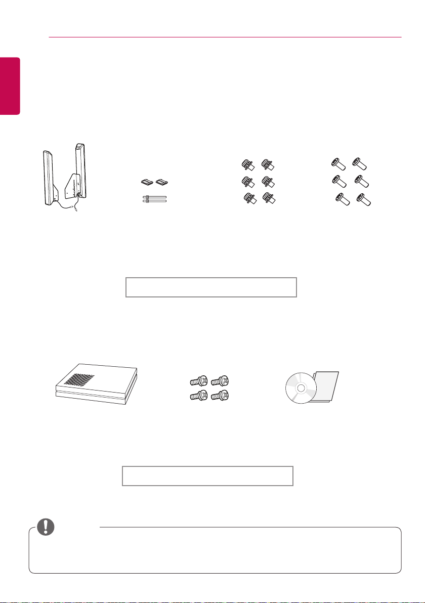
Optional Accessories
Without prior notice, optional accessories are subject to change to improve the performance of the
product, and new accessories may be added. The illustrations in this manual may differ from the actual
product and accessories.
Speakers
SP-2200
Media Player
Cable Holders/
Cable Ties
Media Player Kit
Screws
Diameter 4.0 mm x Pitch
0.7 mm x Length 8 mm
(including spring washer)
Diameter 4.0 mm x Pitch
1.6 mm x Length 10 mm
Speaker Kit
Screws Owner’s Manual
(supplied on CD-ROM) /
Card
Screws
NOTE
• Cable holder/Cable tie may not be available in some areas or for some models.
• Optional accessories are available for some models. If necessary, please purchase them separately.
7
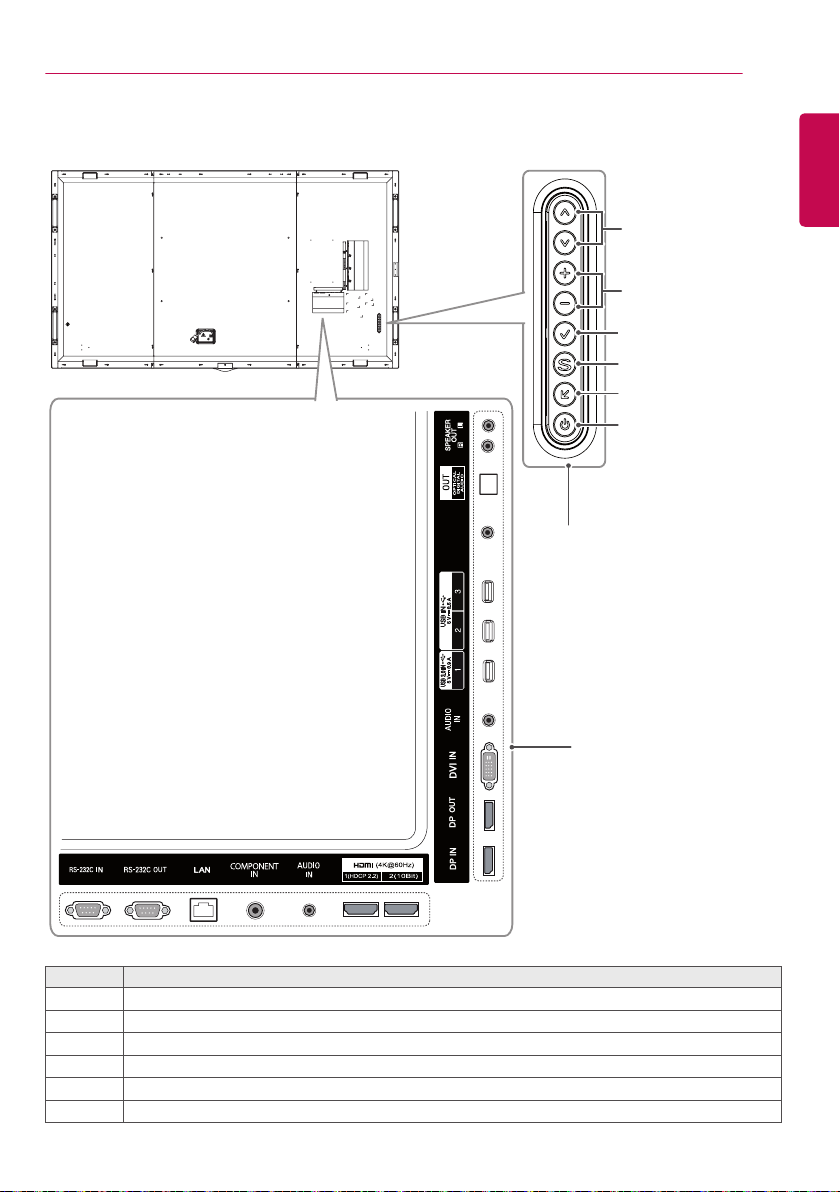
Parts and Buttons
ENGLISH
1
2
3
4
5
6
SENSOR
IR&LIGHT
Screen
Buttons
No. Description
Adjusts up and down.
1
Moves left and right.
2
Displays the current signal and mode.
3
Accesses the main menus, or saves your input and exits the menus.
4
Change the input signal.
5
Turns the power on or off.
6
Input Connectors
ASSEMBLY AND PREPARATION ASSEMBLY AND PREPARATION
8
ENGLISH
Connecting the Speakers
- For certain models only.
1 Connect an input signal cable before
installing the speakers.
2 Mount the speakers by using screws as
shown below. Make sure the power cable is
disconnected before making a connection.
3 Connect the speaker cables noting the
correct polarity. Use cable holders and cable
ties to organize the speaker cables.
NOTE
• Please turn off the power before removing
the cable. Connecting or removing the
speaker cable while turned on may result
in no sound.
9
IR&LIGHT
SENSOR
Connecting Wi-Fi Dongle
1 Attach the Velcro tape provided with the Wi-
Fi dongle to the back of the set.
2 Connect the Wi-Fi dongle and the set using
a USB cable and then attach the dongle to
the set before using.
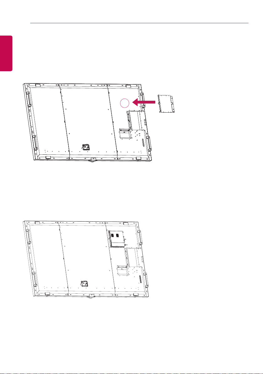
Connecting IR and Light Sensor
When you connect the cable to the product, the
feature for receiving remote control signals is
activated. The IR and light sensor is magnetic.
Attach it to the front edge of the product for use.
[Front]
CAUTION
CAUTION
ENGLISH
NOTE
• Refer to the manual of the Wi-Fi dongle.
• Bluetooth is not supported.
• Refer to the Installation Menu for region
settings.
• The wireless reception may be affected by
the location of the product.
• If there is poor reception in the
recommended location, please change the
location before use.
• Use only the provided Wi-Fi dongle. Other
Wi-Fi dongles may not work properly.
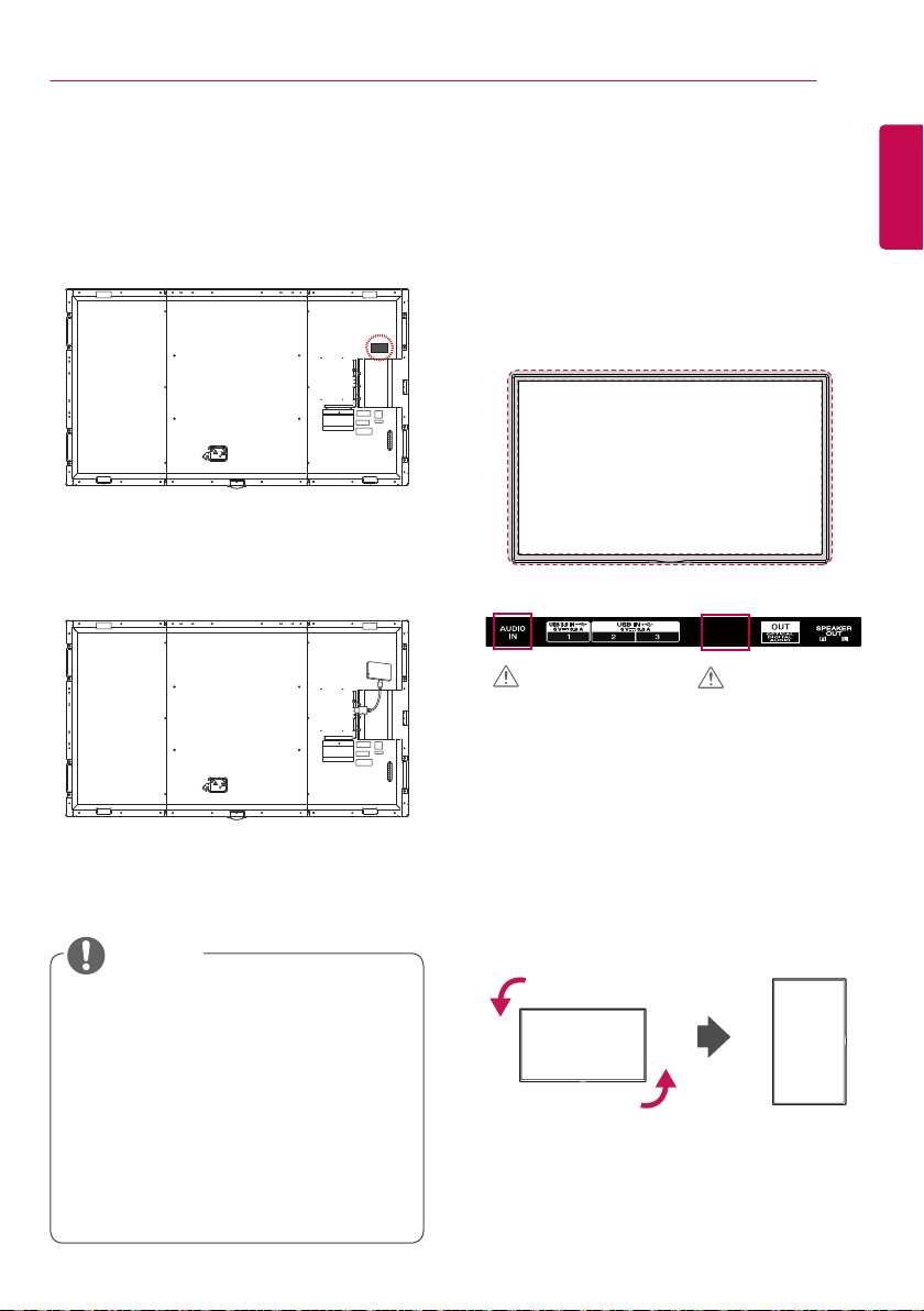
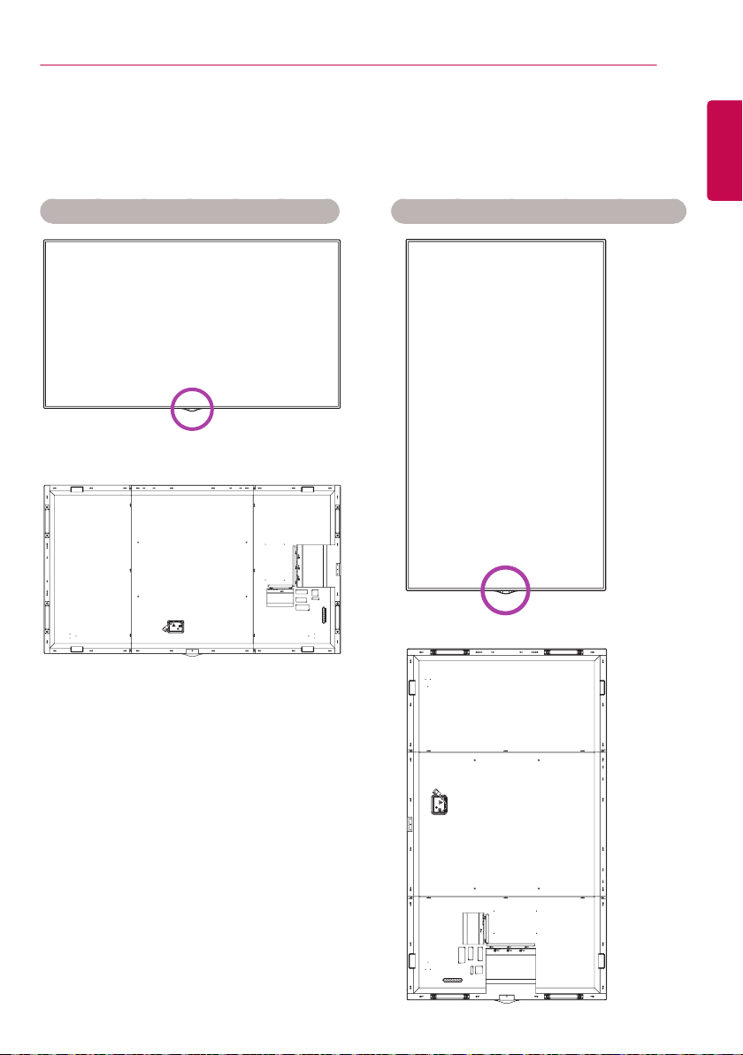
Portrait Layout
When installing in a portrait layout, rotate the
monitor counterclockwise 90 degrees (when
facing the screen).
ASSEMBLY AND PREPARATION ASSEMBLY AND PREPARATION
10
ENGLISH
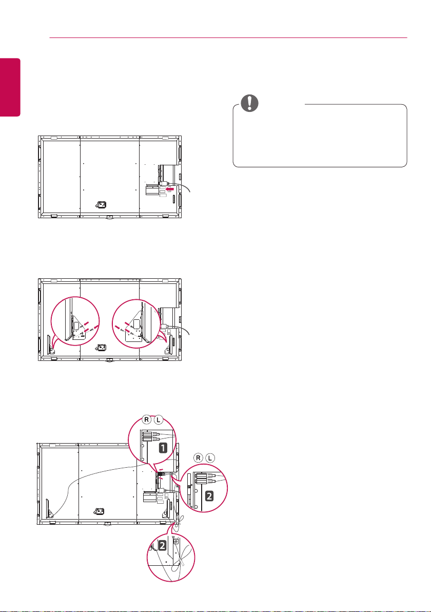
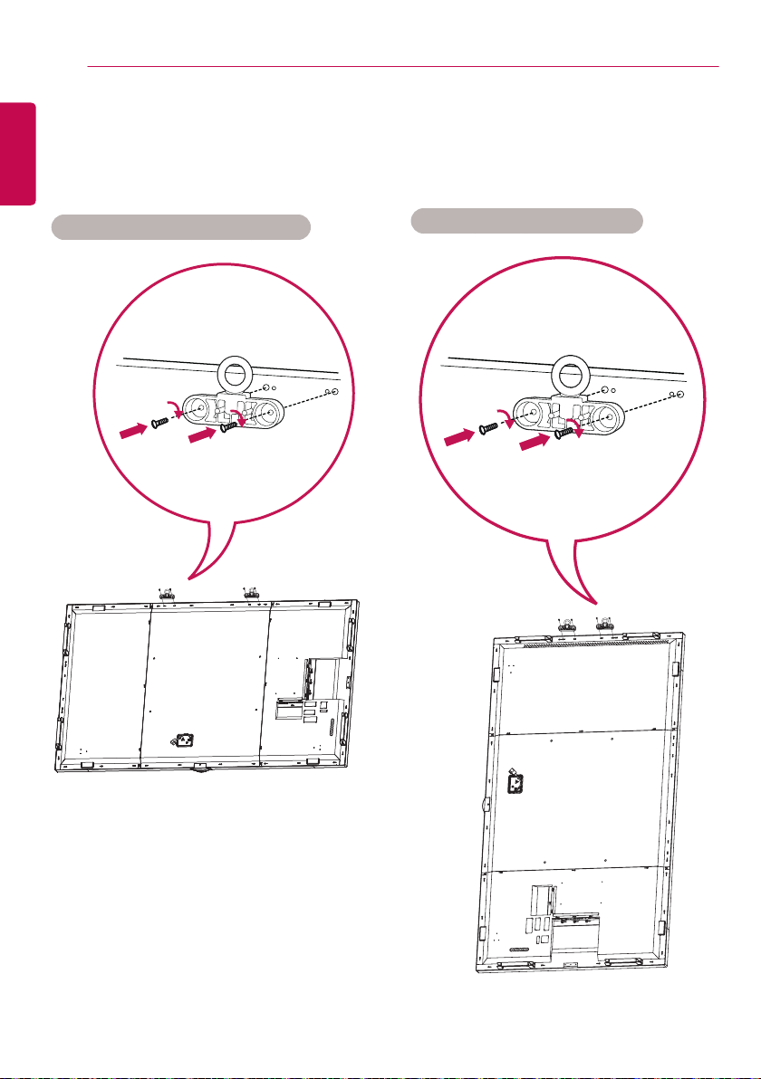
Connecting the Eye-Bolt Bracket
The eye-bolt bracket is designed to be used to lift the set up. Attach the bracket to the product using the
two screws provided.
Installing in Landscape Position
Installing in Portrait Position
11
Attaching the Detachable Logo
Use one screw, inserted from behind, to attach the detachable logo to the monitor. You can position the
logo according to the monitor’s direction.
When the monitor is in the horizontal position
When the monitor is in the vertical position
ENGLISH
ASSEMBLY AND PREPARATION ASSEMBLY AND PREPARATION
12
ENGLISH
How to Install the Guide Bracket
Attach the media player to the guide bracket with 4 fixing screws.
13
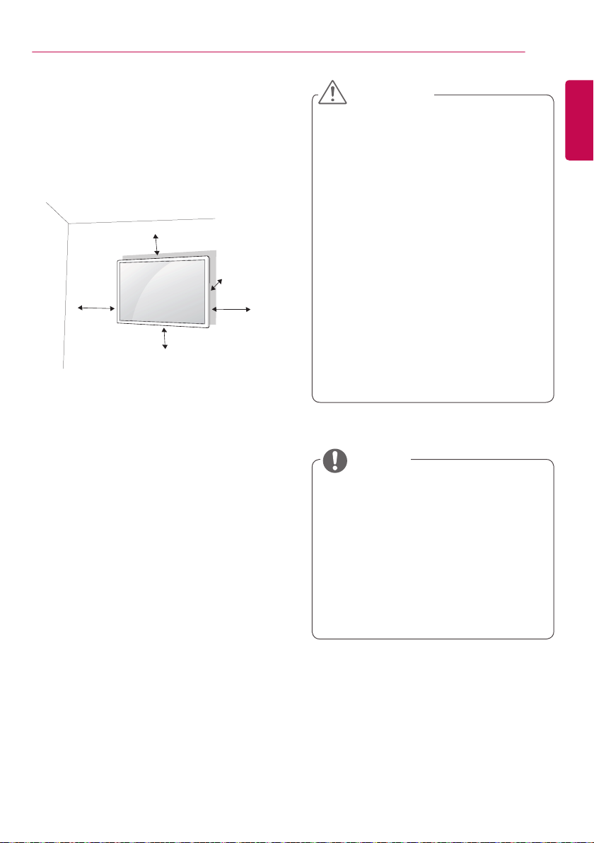
Installing on a Wall
For proper ventilation, allow a clearance of 10
cm on each side and from the wall. Detailed
installation instructions are available from your
dealer, see the optional Tilt Wall Mounting
Bracket Installation and Setup Guide.
10 cm
10 cm
10 cm
10 cm
To install your monitor on a wall, attach a wall
mounting bracket (optional part) to the back of
the monitor.
Make sure that the wall mounting bracket is
securely fixed to the monitor and to the wall.
1. Use only screws and wall mounting brackets
that conform to VESA standards.
2. Screws which are longer than standard
length may damage the inside of the
monitor.
3. A non-VESA standard screw may damage
the product and cause the monitor to fall.
LG Electronics is not liable for any accidents
related to the use of non-standard screws.
4. Please use VESA standard as below.
• 785 mm and above
* Fixing screws: Diameter 8.0 mm x Pitch
1.25 mm x Length 14 mm
* Wall mounting screw spec. (M8 screw)
- Minimum ultimate tensile load :
Min. 12,100N (1,230 kgf)
- Proofing Load : Min. 8,840N (902 kgf)
10 cm
CAUTION
• Disconnect the power cord before moving or
installing the monitor to avoid risk of electric
shock.
• If you install the monitor on a ceiling
or slanted wall, it may fall and result in
injury. Use an authorized LG wall mount
and contact your local dealer or qualified
personnel to assist with the installation.
• Do not over tighten the screws as this may
damage the monitor and void your warranty.
• Use only screws and wall mounting brackets
that meet the VESA standard. Any damage
or injuries caused by misuse or use of
improper accessories are not covered by the
warranty.
• To prevent injury, this apparatus must be
securely attached to the wall in accordance
with the installation instructions. (This only
pertains to Australia and New Zealand.)
NOTE
• The wall mount kit includes the installation
guide and all necessary parts.
• The wall mounting bracket is optional. You
can obtain additional accessories from your
local dealer.
• The length of screws required may differ
depending on the wall mount. Be sure to
use the correct length.
• For more information, please refer to the
guide provided with the wall mount.
ENGLISH
REMOTE CONTROL REMOTE CONTROL
14
ENGLISH
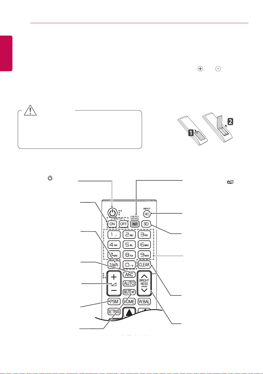
REMOTE CONTROL
The descriptions in this manual are based on the buttons on the remote control. Please read this
manual carefully to use the monitor correctly.
To install batteries, open the battery cover, place batteries (1.5 V AAA) matching and terminals to
the labels inside the compartment, and close the battery cover.
To remove the batteries, perform the installation actions in reverse. The illustrations may differ from the
actual accessories.
CAUTION
• Do not mix old and new batteries, as this may
damage the remote control.
• Be sure to point the remote control toward the
remote control sensor on the monitor.
Turns the monitor on or off.
(POWER)
MONITOR ON
Turns the monitor on.
MONITOR OFF
Turns the monitor off.
1/a/A Button
Toggles between numerical and
alphabetical.
(Depending upon the model, this
feature may not be supported.)
ARC
Selects the Aspect Ratio
mode.
Volume Up/Down
Button
Adjusts the volume.
PSM
Selects the Picture Mode.
MUTE
Mutes all sounds.
ENERGY SAVING( )
Adjusts the brightness of
the picture to reduce energy
consumption.
INPUT
Selects the input mode.
3D
This model does not support
this.
Number and Alphabet
buttons
Enters numerical or alphabetical
characters depending upon the
setting.
(Depending upon the model, this
feature may not be supported.)
CLEAR
Deletes the entered numerical
or alphabetical character.
(Depending upon the model, this
feature may not be supported.)
BRIGHTNESS Button
Adjusts the brightness of the
display. PAGE Function is not
supported in the this model.
(Depending upon the model, this
feature may not be supported.)
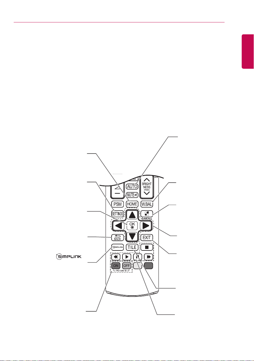
Activates the Launcher.
HOME
SETTINGS
Accesses the main menus or
saves your input and exit menus.
15
ENGLISH
AUTO
Automatically adjusts picture
position and minimizes
image instability (available
for RGB input only).
(Depending upon the model,
this feature may not be
supported.)
W.BAL
This model does not support
this.
Selects menus or options and
OK
confirms your input.
BACK
Allows you to move back one step
in the user interaction function.
Allows you to control various
multimedia devices to enjoy
multimedia simply by using
the remote control through the
SimpLink menu.
(Depending upon the model, this
feature may not be supported.)
ID ON/OFF
When the Picture ID number
matches the Set ID number, you
can control whichever monitor you
want in multi-display format.
S.MENU
SuperSign menu key
(Depending upon the model,
this feature may not be
supported.)
Navigation Buttons
Scrolls through menus or
options.
Exit
Quit all OSD tasks and
applications.
TILE
This model does not support
this.
USB Menu Control
Buttons
Controls media playback.
MAKING CONNECTIONS MAKING CONNECTIONS
16
ENGLISH
MAKING CONNECTIONS
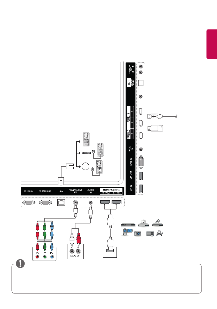
You can connect various external devices to your monitor. Change the input mode and select the
external device you want to connect. For more information about external device connections, see the
user manual provided with each device.
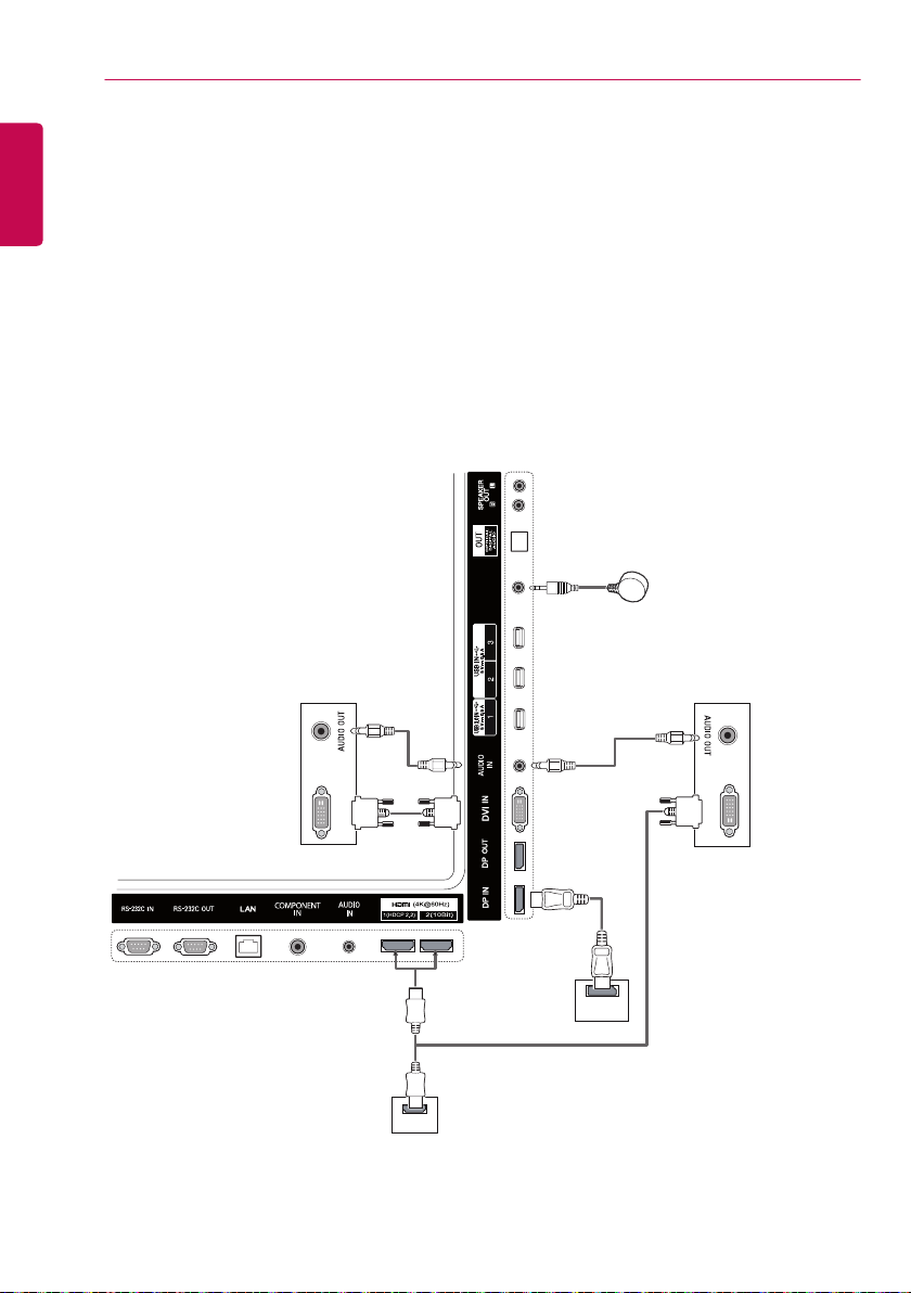
Connecting to a PC
The illustrations may differ from the actual accessories. Some of the cables are not provided.
This monitor supports the Plug & Play* feature.
* Plug & Play: a feature that enables a PC to recognize devices attached by the user without device
configuration or user intervention when powering up.
SENSOR
IR&LIGHT
(not
included)
(not included)
DVI OUT
(not
included)
DVI OUT
(not
included)
DP OUT
HDMI
17
NOTE
• For the best image quality, using the monitor with HDMI connection is recommended.
• To comply with the standard specifications of the product, use a shielded interface cable with a
ferrite core, such as a DVI cable.
• If you turn the monitor on when the set is cold, the screen may flicker. This is normal.
• Sometimes red, green, or blue spots may appear on the screen. This is normal.
• Use a High Speed HDMI
®/TM
cable.
• If you cannot hear any sound in HDMI mode please check your PC settings. Some PCs require
you to manually change the default audio output to HDMI.
• If you want to use HDMI-PC mode, you must set your PC/DTV to PC mode.
• You may experience compatibility issues if you use HDMI-PC mode.
• Make sure the power cable is disconnected.
• Use a certified cable with the HDMI logo attached. If you do not use a certified HDMI cable, the
screen may not display or a connection error may occur.
• Recommended HDMI cable types
- High-Speed HDMI
- High-Speed HDMI
®/TM
cable
®/TM
cable with Ethernet
CAUTION
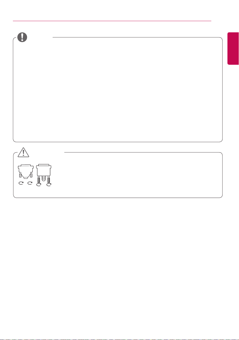
• Connect the signal input cable and tighten it by turning the screws clockwise.
• Do not press the screen with your finger for a prolonged period as this may
result in temporary distortion on the screen.
• Avoid displaying static images on the screen for a long period of time to
prevent image burn. Use a screensaver if possible.
• A wireless communication device near your monitor can affect the image.
ENGLISH
MAKING CONNECTIONS MAKING CONNECTIONS
18
ENGLISH
HDMI (4K @ 60 Hz) input 1 (HDCP2.2), 2 (10 Bit)
HDMI (4K @ 60 Hz) input ports: When using HDMI (4K @ 60 Hz) input port 2 (10-bit), use the provided
HDMI cable. When using an HDMI cable that was not provided, please use a high-speed HDMI cable
(shorter than 3 meters). (Information may vary depending on the model.)
4K@60 Hz input supported formats
Resolution Vertical frequency (Hz) Color depth
HDMI1 HDMI2
8 bit 8 bit 10 bit
3840 X 2160p
59.94
60
YCbCr 4:2:0 YCbCr 4:2:0
― YCbCr 4:2:2
― YCbCr 4:4:4 ―
― RGB 4:4:4 ―
• HDMI specifications may vary depending on the input port. Check the specifications of each device
before connecting.
• HDMI input port 2 is best suited for 4K at 60 Hz (4:4:4, 4:2:2) to enjoy high definition video. However,
video or audio may not be supported depending on the specifications of the external devices. In that
case, please connect to another HDMI port.
NOTE
• DISPLAYPORT does not support Deep Color (YCbCr 4:2:0, YCbCr 4:2:2).
HDMI UHD Deep Colour
Remote Control (HOME) HDMI UHD Deep Colour
• HDMI2 port supports UHD Deep Colour.
• If the device connected to HDMI2 also supports UHD Deep Colour, your picture may be clearer.
• However, if the device doesn’t support it, it may not work properly.
• In that case, connect the device to a different HDMI port or change the TV’s UHD Deep Colour setting
to OFF.
19
External Device Connection
Connect a HD receiver, DVD, or VCR player to the monitor and select an appropriate input mode.
The illustrations may differ from the actual accessories. Some of the cables are not provided. For
the best picture and sound quality, connecting external devices to your monitor using HDMI cables is
recommended.
SENSOR
IR&LIGHT
OR
Direct Connection/
Using the Router/
Using the Internet
Network
(not included)
USB
(not included)
ENGLISH
(not included)
(not
included)
HDMI
HD Receiver/DVD/VCR
Camcorder/Camera/Gaming Device
NOTE
• If you connect a gaming device to the monitor, use the cable provided with the gaming device.
• It is recommended to use the speakers that are provided as optional accessories.
• Use a High Speed HDMI
• High Speed HDMI
®/TM
®/TM
cable.
cables transmit a HD signal up to 1080p and higher.
ENTERTAINMENT ENTERTAINMENT
20
ENGLISH
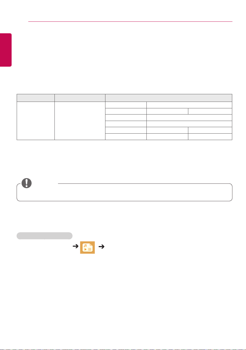
Using the Input List
Remote Control (HOME)
Input Mode Description
HDMI1
HDMI2
DISPLAYPORT
DVI
COMPONENT
You can watch content on a PC,
DVD player, Digital set-top box,
and other high definition devices.
ENTERTAINMENT
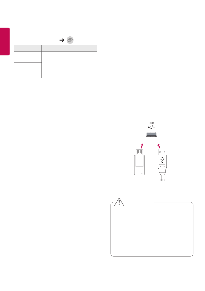
Using My Media
Connecting USB storage devices
Connect a USB storage device such as a USB
flash memory or an external hard drive to the
display and use multimedia features.
Connect a USB flash memory or USB memory
card reader to the display as shown in the
following illustration.
OR
CAUTION
• Do not turn off the monitor or remove a
USB storage device when the My Media
screen is activated. This could result in
loss of files or damage to the USB storage
device.
• Back up files you have saved on a USB
storage device frequently, as loss or
damage to the files may be not covered by
the warranty.
 Loading...