

LG 776FM, FM776F-EA DISASSEMBLY
DISASSEMBLY
- 9 -
(b)
(b)
(a)
(a)
(c)
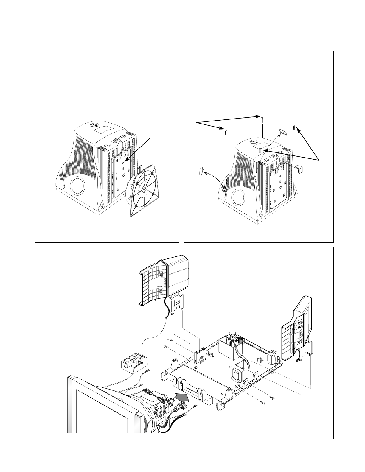
3. SPEAKER ASS’Y REMOVAL
1) Remove four screws (a).
2) Disconnect P802 and P4.
3) Remove the Speaker Ass’y.
2. BACK COVER REMOVAL
1) Remove two screw covers (a).
2) Remove four screws (b) from the Back Cover.
3) Remove the Signal Cap (c).
4) Slide the Back Cover away from the Front
Cabinet of the monitor.
P802
(to P4)
(a)
(a)
(a)
(a)
(a)
1. TILT/SWIVEL REMOVAL
1) Set the monitor face downward.
2) Pressing the latch (a), carefully remove
the Tilt/Swivel by pulling it upward.
- 10 -
(a)
(b)
(b)
(a)
P704
P804
P803
P802
P502
P501
P401
P201
P701
SET
P902
P801
(a)
(b)
(a)
(c)
(c)
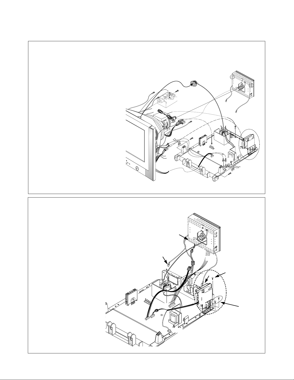
4. TOTAL CHASSIS ASSEMBLY REMOVAL
1) Disconnect P902 (Degaussing pin),
P704 (DY pin), P502, P501 and P701
from the Main PCB.
2) Disconnect P401.
3) Disconnect eight connects (a).
4) Carefully separate the CDT Board
Assembly from the CDT neck.
5) Discharge the remaining static
electricity by shorting between
the Anode Cap and the CDT ground.
6) Disconnect the Anode Cap
from the CDT.
7) Disconnect P801, P802, P803, P804.
8) Remove the screw (b).
9) Remove the MIC Phone Assembly.
10) Remove two screws (c).
11) Remove the Total Chassis Assembly
from the Main Frame.
(a)
5. VIDEO PCB ASSEMBLY & AUDIO ASSEMBLY REMOVAL
1) Remove three screws (a).
2) Disconnect P1, P2, P3.
3) Remove the Audio Assembly.
4) Remove three screws (a).
5) Disconnect P301, P302, and Pin (b).
6) Remove the Video PCB Assembly.
(b)
(a)
P301
P302
P1
P3
P702
P2
P403
P402
P904
 Loading...