

LG 60PZ95V - MU - 60"" Plasma Panel, MU-60PZ95V Owner's Manual

P
SMANUAL
MODELS • MU-60PZ95V
_fore operating
the Monffor.
rel_e
service.
Warning
I
WARNING/CAUTION"
TO REDUCE THE RiSK OF ELECTRIC SHOCK DO NOT REMOVE COVER (OR BACK). NO USER
SERVICEABLE PARTS iNSIDE REFER TO QUALIFIED SERVICE PERSONNEL,
WARNIN G/CAUTION
_& he lightning flash w_th arrowhead symbol, within an equilateral triangle, is intoned to alert the ucer to
the presence of uninsulated 'd_gerous voltage" within the product's enclosu_ that may be of suf_-
cient magnitude to constitute a risk of electric shock to persons.
The exclamation point w_hin an equilateral triangle is intended to alert the user to the presence of
important oper_ing and maintenance (sewicing) instructions in the literature accompanying the appli-
_ce.
WARNINGICAUTION"
TO PREVENT FIRE OR SHOCK HA.ZARDS_ DO NOT EXPOSE THiS PRODUCT TO RAIN OR MOISTURE.
FCC NOTICE
• A Class B digital device
This _uipment has been tested and found to comply with the limi_ for a Class B digital device, pursuant to Pax
15 of the FCC Rules, These limits are design_ to provide reasonable protection against harmful interference in
a residential installation This equipment generates, uses and can radiate radio frequency energy and, if not
instatled and used in accordance with the instructions, may cause harmful interference to radio communications.
However, there is no guarantee th_ interference will net occur in a particular inst_lation, If this equipment does
cause harmful interference to radio or television reception which can be determined by turning the equipment off
and on, the user is encouraged to try to correct the interference by one or more of the following measures:
Reorient or relocate the receiving antenna.
- increase the separation be_een the equipment and receiver.
- Connect the equipment into _ outlet on a circuit different from that to which the receiver is connected.
Conceit the dealer or an experiensed radio1_\J technician for he_p.
• Any changes or modifications not expressly approved by the party responsible for compli-
ance could void the user's authority to operate the equipment.
CAUTION:
Do not attempt to _ify this product in any way wi_out written authoriz_on from LG Eie_onics Unauthorized
ification could vo_ the useCs authority to operate this product
COMPLIANCE:
The responsible party for this product's compliance is:
LG E_ectronics U.S.A., Inc
1000 Sylvan Avenue, Englewood Cliffs, NJ 07632
1-_-243-0000
http://www.lgusa.com
WARNING/CAUTION
TO REDUCE THE RISK OF FIRE AND ELECTRIC SHOCK, DO NOT EXPOSE THIS PRODUCT TO
RAIN OR MOISTURE.
2 Plasma Monitor
J
Cti0ns
f
Important safeguards for you and your new product
Your product has been manufactured and tested wffh your safety in mind However, improper use can resuff in potential elec o
trica_ sh_k or fire hazards. To avoid defeating the safeguards that have been buiff into your new product, please read and
observe the following safety pain_ when installing and using your new product, and save them for future reference.
Observing the simpJe precautions discussed in this bookret can he_p you get many years of enjey_nt and safe oparation
that are b,uiff into your new product.
This product compiies with all applicable U_S Feder_ safety requirements, and those of the Canadian Standards
Association_
t. Read these inatructtons.
2. Keep these instruetions,
3. Heed all warnings.
4. Follow all instructions.
5. Do not use this apparatus near water.
6, Clean only with d_ cloth.
7. _ not block any ventilaUon openings, install in accordance with the _nufactu_r's _natruct|ons.
8. Do not install near any heat sources such as radiators, heat registers, stoves, or other apparatus (including ampli-
fiers)that produce heat,
9. Do not defeat the safely purpose of the polarized or groundtng-typa plug. A po_arlzed plug has two b_ades with
one wider than the other. A grounding type plug has two blades and a third grounding prong, The w_de blade or the
third prong are provided for your safety, if the provided plug d_s not fit into your outlet, consult an electrician for
repl_ement of the obsolete outlet,
10. Protect the power cord from being walked on or pinched particularly at plugs, convenience receptacles, and the
point where they exit from the apparatus.
OwneFs Manual 3
Safetytnstruc#ons
Safety Instructions continued
11. Only use attachments/accessories specified by the manufacturer_
t2. Use only with the cart, stand, tripod, bracket, or table specified by the nmnufacturer, or sold with the apparatus.
When a cart is used, use caution when moving the cartJappe_us combination to avoid injury from tipover_
PORTABLE CART WARNUNG
13. Unplug this apparatus during lightning storms or when unused for long periods of time.
t4. Refer all servicing to qua#lied service personnel. Servicing _s required when the apparatus has been damaged
In any way, such as power=supply cord or plug is damaged, liquid has been spllted or objects have fallen into the
apparatus, the apparatus has exposed to rain or moisture, does not operate normally, or has been dropped.
15. Outdoor Use Marking :
WARNING - To Reduce The Risk Of Fire Or Electric Shock, Do Not Expose This Appliance To Rain Or Moisture.
16. Wet LocaUon Marking :
Apperatus shall not be exposed to dripping or splashing and no objects filled w_tb liquids, such as vases, shall
be placed on the apparatus.
4 Plasma Monitor
Safetyinstructions
Warning/Caution ....................... 2
Safety Instructions ......................... 3~4
Introduction
Controls and Connection Options ............. 7
Remote Contro_ Key Functions .............. 8
Installation
_nsta{_ation Instructions .................... 9-10
Extamal Equipment ConnectJons .......... 11~15
VCR Setup ............................... 11
Cable TV Setup ....................... 11
External A!V Sou roe Setup ............... 12
DVD Setup ............................ 12
DTV Setup / Monitor Out Setup ............. 13
PC Setup .......................... 14-15
Operation
Turning on the Monitor ................... 16
Menu Language Selection ............. 16
Picture Menu Options
APC (AUto Picture Control) ................ 17
XD .................................. 17
Color Temperature Control .................. 17
Fleshtone ......................... 18
sRGB ................................ 18
Manua_ Picture Control(APC set to Off option) ,,. 18
Sound Menu Options
DASP (Digital Auto Sound Processing) ....... 19
BBE ............................. 19
AVL (Auto Votume Leveler) ............... 19
Manual Sound Control(DASP set to Off option) , ,20
Timer Menu Options
Clock Setup .............................. 21
OrdOff Tier Setup ..................... 21
Auto Off/Sleep Timer ................... 21
Speciat Menu Options
Key Lock ....................... 22
ISM (Image Sticking Minimization) Method ....
Low Power .................... 23
XD Demo ..................... 23
Menu Rotation for Ve_ Vicing ............ 23
Screen Menu Options
Auto Adjustment ....................... 24
Setting Picture Format ............. 24
Screen Position ........................ 24
Manual Configure , .................... 25
Selecting VG_JXGA Mode .................. 25
Screen Adjustments ..................... 25
Cinema Mode Setup ...................... 25
Luminance Noise Reduction .............. 26
Initializing (Reset to otigin_ factory value) ..... 26
Split Zoom ............................ 26
PIP (Picture In-Picture)!Double Window Feature
Watching PIP/Doub,ie Window .............. 27
Swapping the P_P/Double Window ....... 27
_ an t_ _ Source for PIP_ Wind_ ,27
Moving the PIP(PIP Mode only) ........... 27
PiP Size . ............................. 27
PIP Transparency (PiP Mode only) .......... 27
External Control Device Setup ................ 28~33
IR Code information ....................... 34~35
Troubleshooting Checklist ....................... 36
i'_intenance ................................. 37
Speclftcations ................................ :38
Warranty ................................... 39~40
Owner's Manual 5
Introduction
lnt
What is a Plasma Display Panel (PDP)?
_fv_ltage is apptied to gas within g_asspanels, ultraviolet rays are produced and fused with a fluorescent substance. At that
instant, light is emitted. A Plasma Display is a next generation fiat Display using this phenomenon.
160 °' - Wide angle range of vision
Your fiat panel plasma screen offers an exceptionally broad viewing angle _-over 160 d_rees, This means that the display is
dear and visibte to viewers who can see the screen _ywhere in the room,
Wide Screen
The screen of the Plasma Display is 60" so wide that your viewing experience is as if you are in a theater,
Multimedia
Connect your p_asmadisplay to a PC and you can use itfor conferencing, games, and intemet browsing. The Picture inoPicture
feature allows you to view your PC and video images simu_neous_y
Versatile
The _ightweight and thin size makes it easy to installyour ptasma display in a variety of locotionswhere conventional TVs wou_d
not fit,
The PDP Manufacturing Process: Why minute colored dots may be present on the PDP screen
The PDP (P_asm_3 Display Pane[) which is the display device of this product is composed of 09 to 2_2 million cells, A few celF
defects wi_Unormally occur in the PDP manufacturing process Several minute colored dots visible on the screen should be accept-
able, This also occurs in other PDP manufacturers products and the tiny dets appearing dees not mean that this PDP is defective,
Thus a few celt defects are not sufficient cau_ for the PDP to be exchanged or returned, Our produ_on technology is designed
to minimize ceil defects during the manufacture and operation of his product_
Cooling Fan Noise
In the _ame way that a fan is used in a PC computer to keep the CPU (Centra_ Processing Unit) coo_, the PDP is equipped with
cooling fans to coo[ the Monitor and improve its reliability. Therefore, a certain [eve[ of noise could occur while the fans are operat-
ing and cooling the PDP,
The fan noise d_sn't have any negative effect on the PDP's efficiency or reliability. The noise from these fans is nor_l during the
operation of this product. We hope you understand that a ce_in level of noise from the cooling fans is acceptable and is not suffi-
cient _tJse for the PD, P to be exchanged or returned.
6 Plasma Monitor
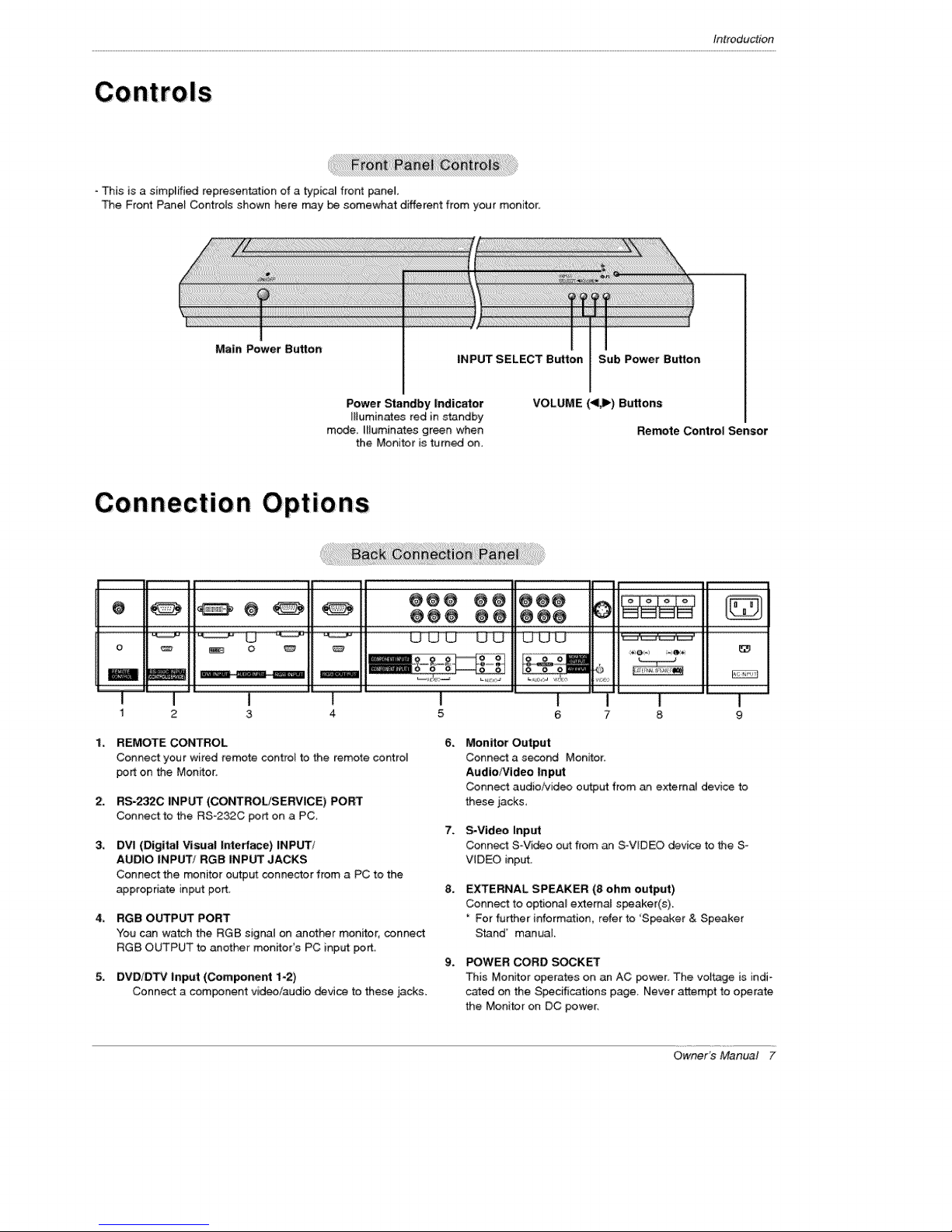
- This is a simplified reptesen_tion of a typicaJ front panel
The Front Panet Co.rots shown here may be somewhat different from your monitor:
Introduction
Main Power Button
Power Standby Indicator
Muminates red in standby
mode. I_luminates green when
the Monitor is turned on.
O O
O
o _
i
1 2
REMOTE CONTROL
Connect your wired _emote cont:ro_ to the remote control
pert on the Monitor:
RS-2320 _NPUT (COt_ROL/SERVICE) PORT
Connect to the RS_232C port on a PC.
DVI (Digital Visua| Interface) INPUT/
AUDIO INPUT! RGB INPUT JACKS
Connect the monitor output connector from a PC to the
appropriate input port
RGB OUTPUT PORT
You can watch the RGB signal on another monitor, connect
RGB OUTPUT to another monitors PC input port
DVD/D_ input (Component 1-2)
Connect a component video/audio _vice to these jacks.
3 4
INPUT SELECT Button Sub Power Button
VOLUME (<_) Buttons
@@@ @@ @@@
_ _ _'_'
I
5
6_
Monitor Output
Conn_ a s_nd Mon_tor:
Audio/Video Input
Connect audio/video output from an external device to
these jacks,
7_
S-Video Input
Conn_ S-Vi_o out from an S°VIDEO device to the S-
VIDEO input,
8.
EXTERNAL SPEAKER (8 ohm output)
Connect to optional external speaker(s).
For further information, refer to 'S_aker & Speaker
Stand' manual.
9_
POWER CORD SOCK_
This Monitor operates on an AC power_ The voltage is indi-
cared on the S_cifications page, Never attempt to operate
the Monitor on DC power,
Remote Control Sensor
I l
6 7 8
OwneFs Manual 7
Introduction
Remote Control Key Functions
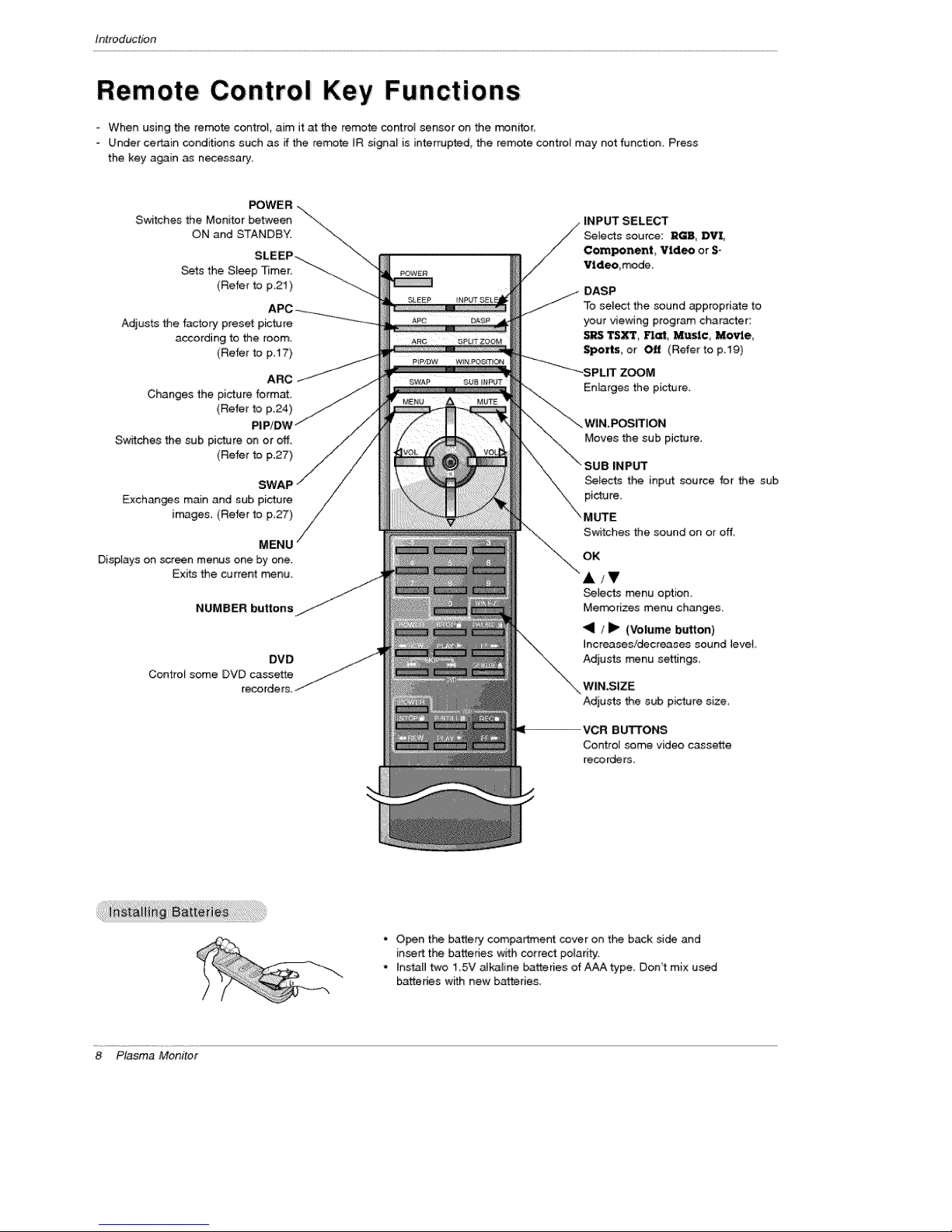
- When using the remote controI, aim it at the remote control sensor on the monifor,
- Under certain conditions such as if the remote [R signa_ is interrupted, the remote control may not function. Press
the key again _ necessary.
Swifches the Monitor between \\
ON and STANDBY, "_\\
Sets the Sleep 'Timer. "--__
Adjusts the factory preset picture
according to the room,
Changes the picture format
Switches the sub picture on or off.
Exchanges main and sub picture
images (Refer to p_27)
Displays on screen menus one by one.
Exits the current Fr_nu_
POWER -.\
SLEEP-_... _'-.
(Refer to p.21) ...._
APC ___ ....
(Refer to p,I7)
ARC/J
(Refer to p.24)
PIP/DV_
(Refer to p127)
MENU
NUMBER buttons
Control some DVD cassette
DVD
recorders.
POWER
DASP
To select the sound appropriate to
your viewing program character:
SRS TS_, Flat, Music Movie,
Sports, or Off (Refer to p,19)
Enlarges the picture.
WIN,POSITION
Moves the sub picture.
INPUT
_lects the input source for the sub
Switches the sound on or off.
OK
A/V
_lects menu option_
Mem#rizes menu changes_
"91 /Jl_ (Volume button)
Increases!decreases sound level
Adjusts menu settings
WIN,SIZE
Adjusts the sub picture size
8 Plasma Monitor
4OR Bu'FrONS
Control _me video cassette
reco rders_
- Open the battery compartment cover on the back side and
insert the batteries with correct po_aritt.
* Install two 15V alkaline batteries of AAA type, Don't mix used
batteries wifh new batteries,
Introduction
i
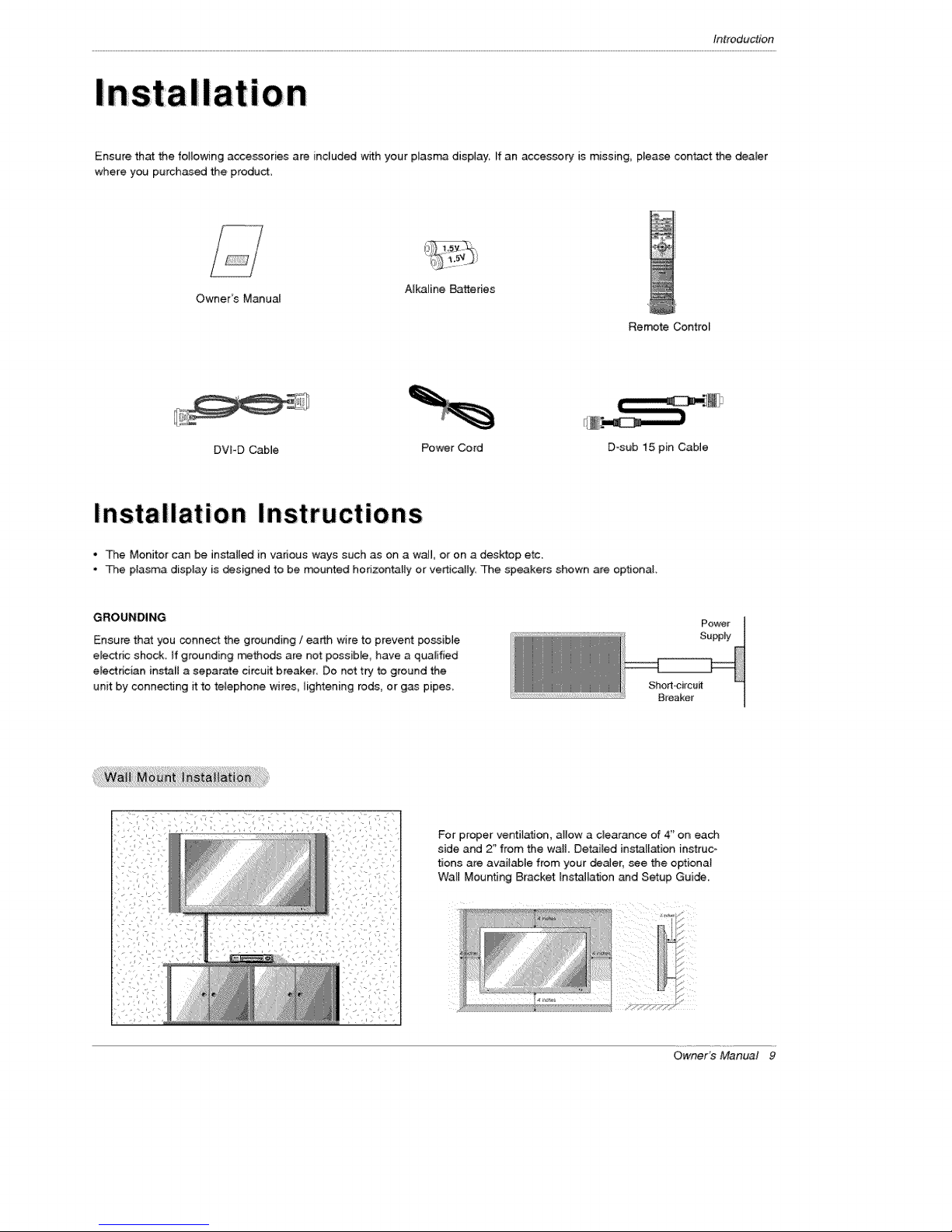
Ensure that the following accessories ate included with your plasma display, ff an accessory is missing, p_ease contact the dea_er
where you purchased the product.
Owner's Manual
DVPD CabJe Power Cord D-sub 15 pin Cable
Alkaline Batteries
Remote Control
InstaIIation Instruc tions
, The Monitor can be insta[[_ in various ways such as on a wail or on a desktop etc.
• The plasma display is designed to be m_unted horizontally or vertically. The speakers shown are optional.
GROUNDING
Ensure that you connect the grounding / earth w{re to prevent po_ibie
electdc shock, ff grounding methods are not passible, have a qualified
electrician instaB a separate circuit breaker Do not try to ground the
unit by connecting it to telephone wires_ lightening rods, or gas pipes.
Power
Supply
Shod-circuff
Breaker
For proper vent#ation, atlow a clearance of 4" on each
side and 2" from the wail Detailed in_l[ation instruco
tions are available from your deaJer, see the optiona}
Wall MountJng Bracket [ns_[ation and Setup Guide.
OwneYs Manual 9
t_talladon
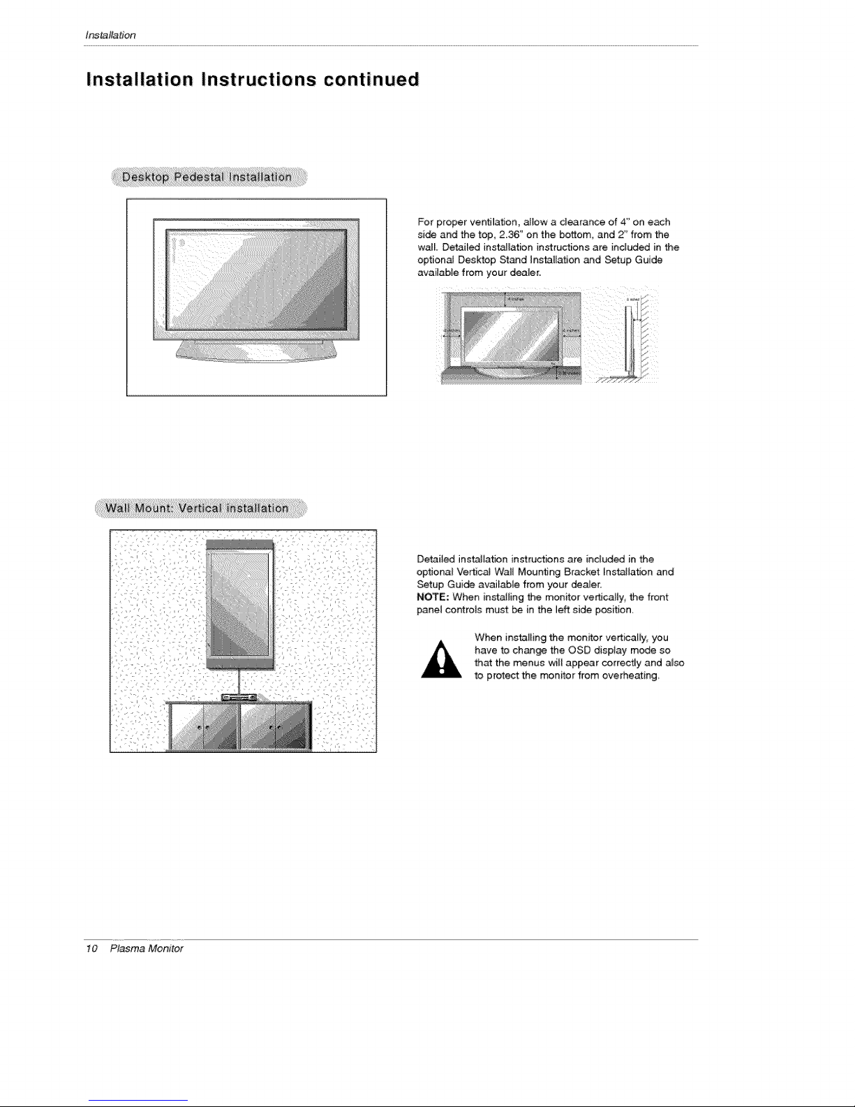
Installation Instructions continued
For proper ventilation, allow a clearance of 4" on each
si_ and the top, 2.36" on the bottom, and 2" from the
wail Detailed ins_lation instructions are included inthe
optional Desktop Stand Installa_on and Setup Guide
available from your dealer.
10 Plasma Monitor
_
Detaiied installation instructions are inciuded in the
optiona{ Ve_cal Wall Mounting Bracket hstall.ation and
Setup Guide avaiEable from your dealer,
NOTE: When installing the monitor ve_cally, the front
panel controls must be in the left side position.
When installing the monrtor verticaliy_ you
have to change the OSD display mode so
that the menus witl appear correctly and a_so
to protect the monitor from overheating
Installation
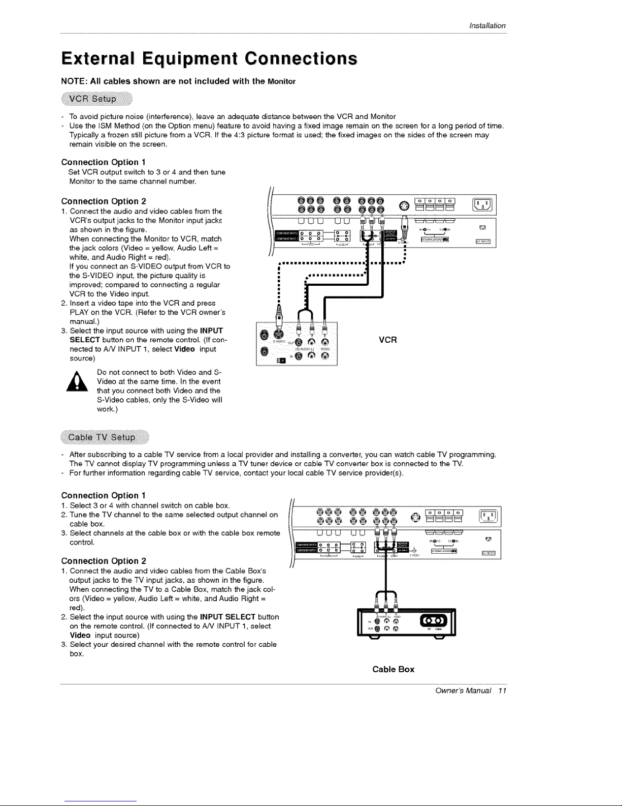
External ipment Connections
NOTE: All cables shown are not included with the Monitor
- To avoid picture noise (interference), _eave an adequate distence between the VCR and Monitor
- Use the ISM Method (on the Option menu) feature to avoid having a fixed image remain on the screen for a long period of time.
Typically a frozen s_Jl[picture from a VCR. [f the 4:3 picture format is used; the fixed images on the sides of the screen may
remain visible on the screen.
Connection Option 1
Set VCR output switch to 3 or 4 and then tune
Monitor to the _me channeMnumber,
Connection Option 2
I, Connect the audio and video cables from the
VCR's output jacks to the Monitor input jack_
as shown in the figure.
When connecting the Monitor to VCR, match
the jack colors (Video = yellow Audio Left =
white, and Audio Right = red).
ff you connect an SWIDEO output from VCR to
the S-WDEO input, the picture quality is
improved; compared to connecting a regumar
VCR to the Vi_o input.
2. insert a video tape into the VCR and press
PLAY on the VCR. (Refer to the VCR owner's
manuaL)
3. Select the input source with using the iNPUT
SELECT button on the remote control (If con-
nected to AiV iNPUT 1, select Video input:
source)
Do not connect to both Video and S-
Video at the san time In the event
that you connect both Video and the
S-Video cab[es_ only the S-Video will
work.)
_mmmmuaaz_ali=lllallsa
!
m
ill llama i1_
- After subscribing to a cable TV service from a ioca_ provider and instaID_g a converter, you can watch cable TV programming.
The TV _nnot display TV programming unless a TV tuner device or cable TV converter _x is oannected to the TV
- }=or further information regarding cable TV service, contact your local cable TV service provider(s).
Connection Option 1
1. Select 3 or 4 with channel switch on cable box
2 Tune the TV channel to the same setected o_put channel on
cable box
3, Select channels at the cable box or with the cabie box remote
control
Connection Option 2
1. Connect the audio and video _b[es from the Cable Box's
outp_ jacks to the TV input _acks, as shown in the figure.
When connecting the TV to a Cable Box, match the jack cor-
ers (Video = ye[[ow_ Audio Left = white, and Audio Right =
red).
2. Select the input sour_ w_h using the iNPUT SELECT button
on the remote cor_roL (ff connected to #JV _NPUT 1 select:
Video input source)
3. _4ect your _sired charmer with the remote control for cable
box.
Cabre Box
Owner's Manual 11

t_taflation
How to conneGt
Connect the audio and video cables from the externat
equipment's output jacks to the Monitor input jacks, as
shown in the figure.
When connecting the Monitor to extema_ equipment, match
the jack colors (Video = yellow; Audio Left = white, and
Audio Right = red).
How to use
1. Select the input source with using the INPUT SELECT but-
ton on the remote control (If connected to AAJ INPUT 1,
select Video input source).
2. Operate the corresponding external equipment. Refer to
external equip_nt operating guide.
Camco_er
Video Game Set
How to connect
1. Connect the DVD video outputs (Y, PB, P_) to the COMPO=
NENT (Y, Pa, PR) INPUT jacks on the Monitor and connect the
DVD audio outputs to the AUDIO INPUT jacks on the Monitor,
as shown in the figure.
2. If your DVD only has an S-Video output jack, connect this to the
S-VIDEO input on the Monitor and connect the DVD audio out*
puts to the AUDIO tNPUT jacks on the Monitor, as shown in the
figure.
NOTE: ff your DVD p_ayer does not have component video output,
use SWideo.
HOW to U_
1_ Turn on the DVD player, insert a DVD_
2, Use the INPUT SELECT button on the remote control to select
Component 1 or Component 2, (If connected to S-VIDEO,
select the Video external input source,)
3. Refer to the DVD player's manua_ for oper_ing instructions,
• Component Input ports
To get better picture quality, connect a DVD player to the com-
ponent input ports as shown below,
Component ports
on the Monitor
Video output ports
on DVD player
DVD
12 Plasma Monitor
 Loading...