

Page 1
PLASMA TV
SERVICE MANUAL
CAUTION
BEFORE SERVICING THE CHASSIS,
READ THE SAFETY PRECAUTIONS IN THIS MANUAL.
CHASSIS : PU13A
MODEL : 60PZ550 50PZ550-UA
MODEL : 60PZ540 50PZ540-UB
North/Latin America http://aic.lgservice.com
Europe/Africa http://eic.lgservice.com
Asia/Oceania http://biz.lgservice.com
Internal Use Only
Printed in Korea
P/NO : MFL67001503(1101-REV00)
Page 2

- 2 -
LGE Internal Use OnlyCopyright ©2011 LG Electronics Inc. All rights reserved.
Only for training and service purposes
CONTENTS
CONTENTS ............................................................................................................................... 2
SAFETY PRECAUTIONS ...........................................................................................................3
SPECIFICATION.........................................................................................................................4
ADJUSTMENT INSTRUCTION ..................................................................................................6
BLOCK DIAGRAM ...................................................................................................................13
EXPLODED VIEW ...................................................................................................................14
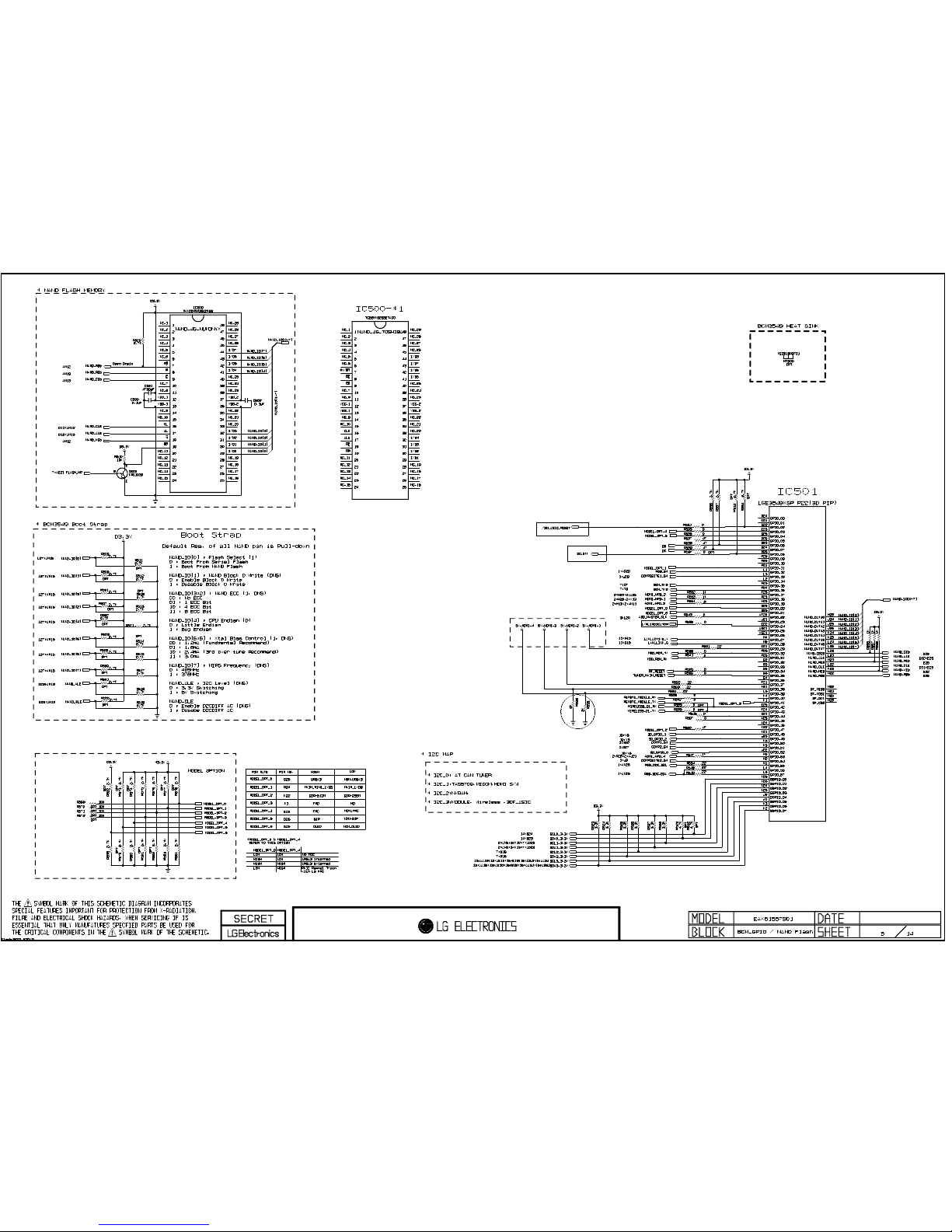
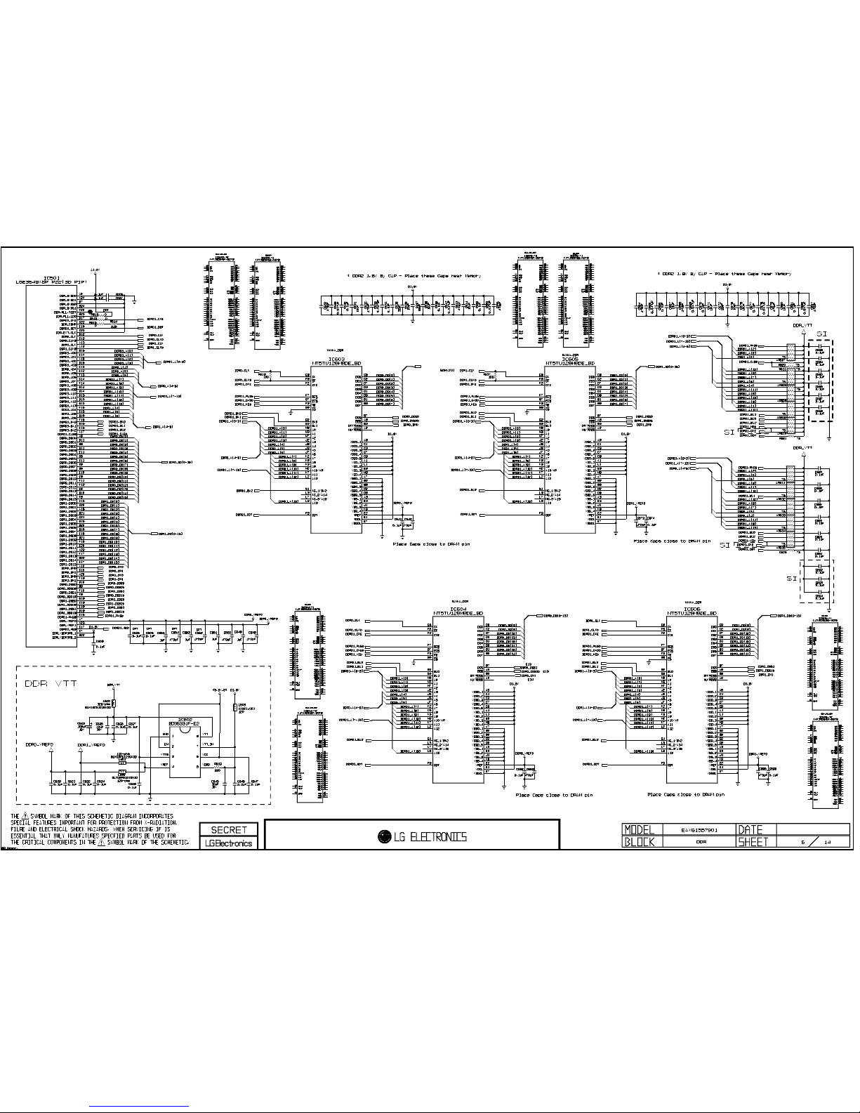
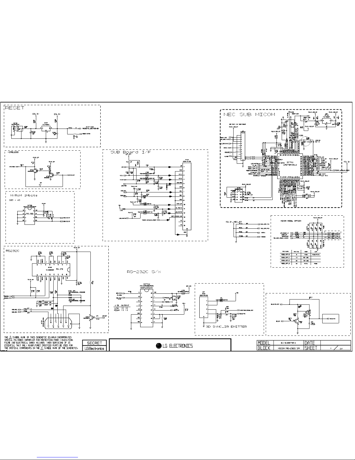
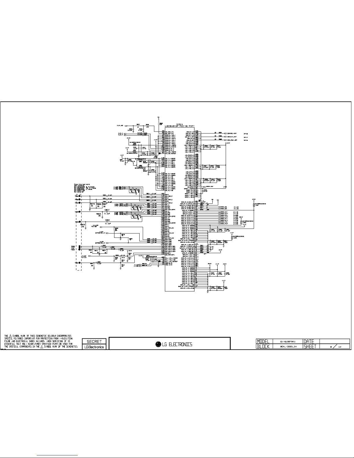
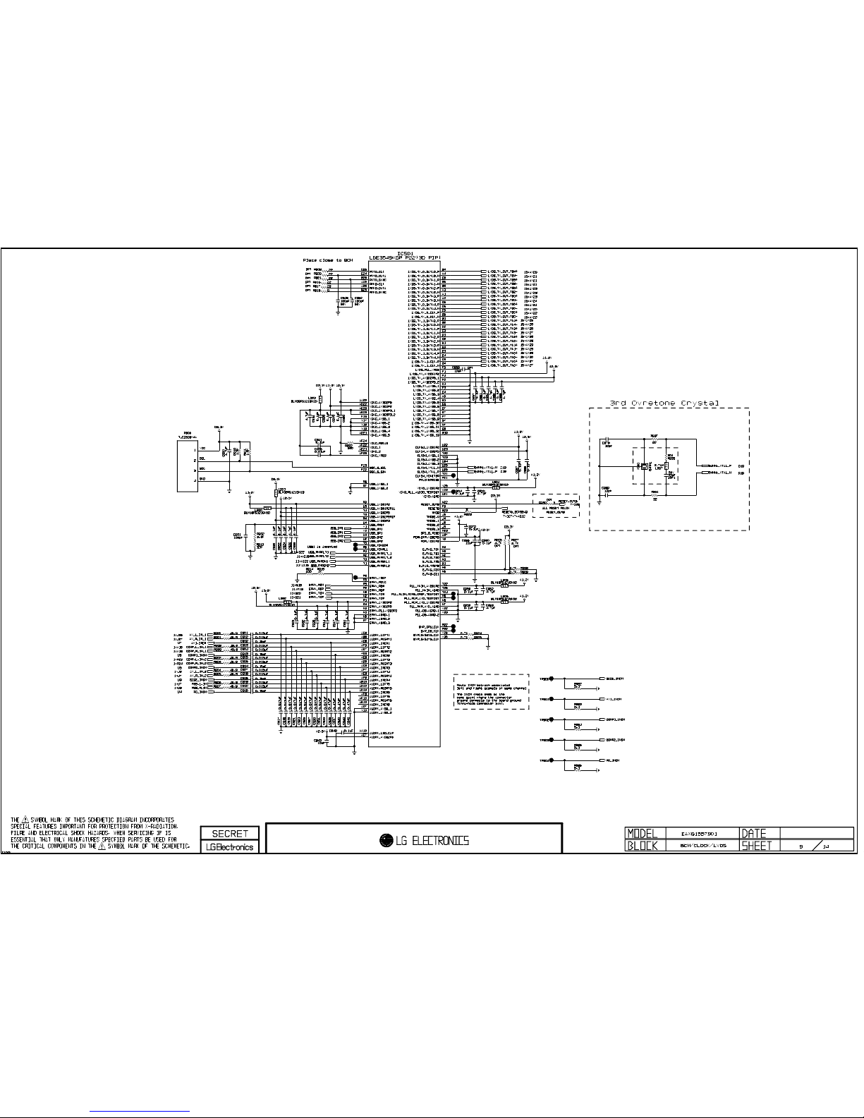
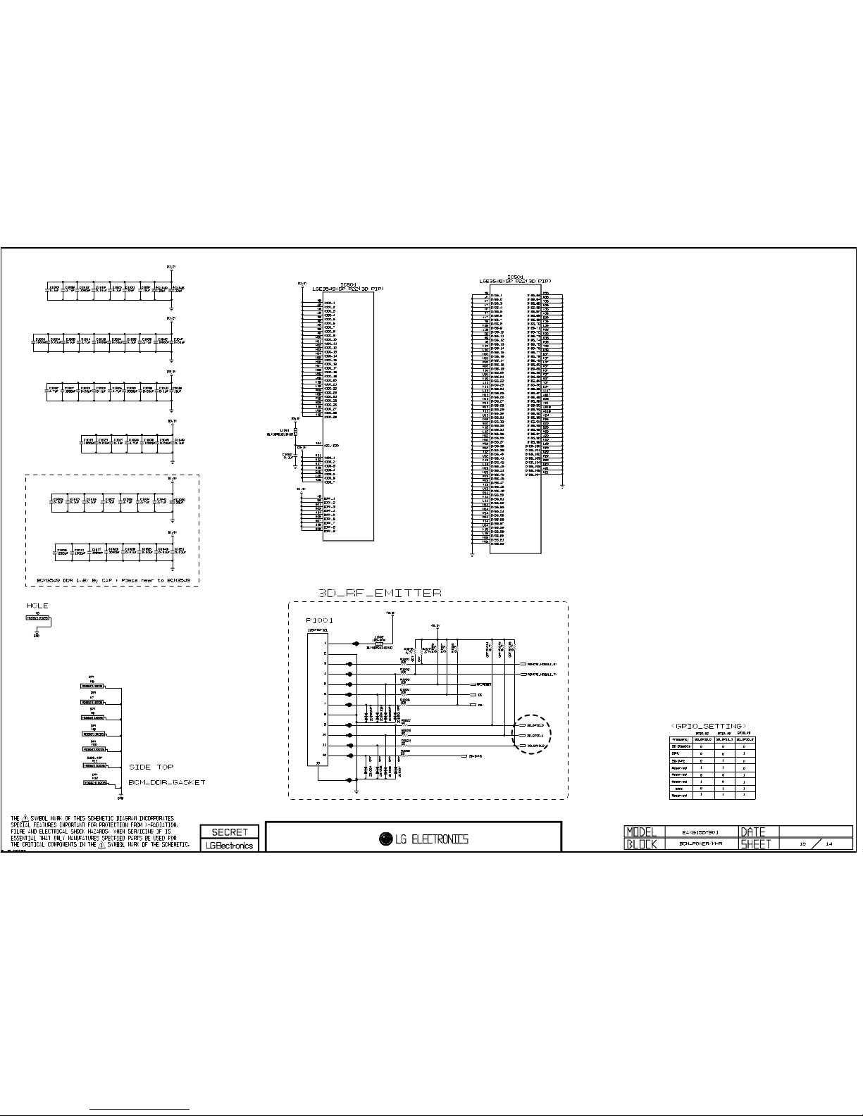
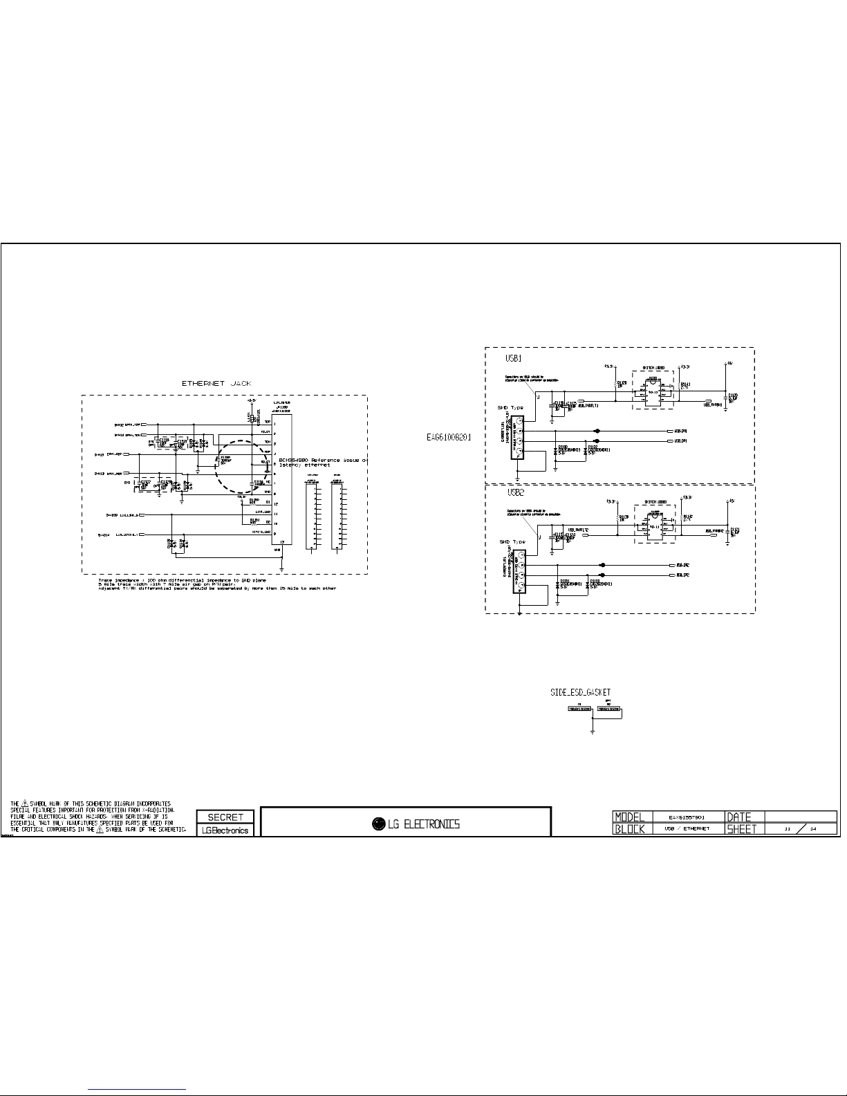
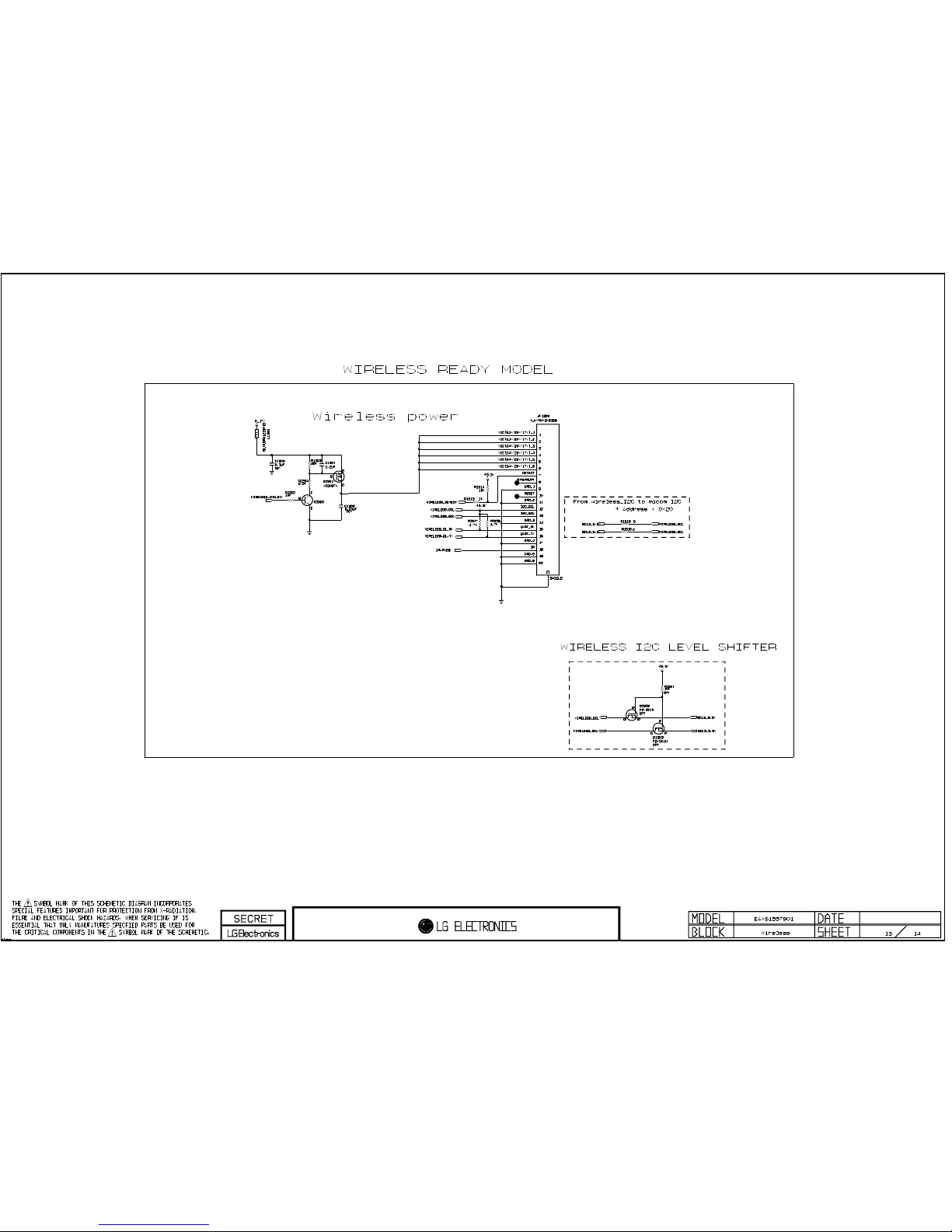
CIRCUIT DIAGRAM .....................................................................................................................
Page 3

- 3 -
LGE Internal Use OnlyCopyright ©2011 LG Electronics Inc. All rights reserved.
Only for training and service purposes
SAFETY PRECAUTIONS
Many electrical and mechanical parts in this chassis have special safety-related characteristics. These parts are identified by in
the Schematic Diagram and Exploded View.
It is essential that these special safety parts should be replaced with the same components as recommended in this manual to
prevent X-RADIATION, Shock, Fire, or other Hazards.
Do not modify the original design without permission of manufacturer.
General Guidance
An isolation Transformer should always be used during the
servicing of a receiver whose chassis is not isolated from the AC
power line. Use a transformer of adequate power rating as this
protects the technician from accidents resulting in personal injury
from electrical shocks.
It will also protect the receiver and it's components from being
damaged by accidental shorts of the circuitry that may be
inadvertently introduced during the service operation.
If any fuse (or Fusible Resistor) in this monitor is blown, replace it
with the specified.
When replacing a high wattage resistor (Oxide Metal Film
Resistor, over 1 W), keep the resistor 10 mm away from PCB.
Keep wires away from high voltage or high temperature parts.
Due to high vacuum and large surface area of picture tube,
extreme care should be used in handling the Picture Tube.
Do not lift the Picture tube by it's Neck.
Leakage Current Cold Check(Antenna Cold Check)
With the instrument AC plug removed from AC source, connect
an electrical jumper across the two AC plug prongs. Place the
AC switch in the on position, connect one lead of ohm-meter to
the AC plug prongs tied together and touch other ohm-meter
lead in turn to each exposed metallic parts such as antenna
terminals, phone jacks, etc.
If the exposed metallic part has a return path to the chassis, the
measured resistance should be between 1 MΩ and 5.2 MΩ.
When the exposed metal has no return path to the chassis the
reading must be infinite.
An other abnormality exists that must be corrected before the
receiver is returned to the customer.
Leakage Current Hot Check (See below Figure)
Plug the AC cord directly into the AC outlet.
Do not use a line Isolation Transformer during this check.
Connect 1.5 K/10watt resistor in parallel with a 0.15 uF capacitor
between a known good earth ground (Water Pipe, Conduit, etc.)
and the exposed metallic parts.
Measure the AC voltage across the resistor using AC voltmeter
with 1000 ohms/volt or more sensitivity.
Reverse plug the AC cord into the AC outlet and repeat AC
voltage measurements for each exposed metallic part. Any
voltage measured must not exceed 0.75 volt RMS which is
corresponds to 0.5 mA.
In case any measurement is out of the limits specified, there is
possibility of shock hazard and the set must be checked and
repaired before it is returned to the customer.
Leakage Current Hot Check circuit
1.5 Kohm/10W
To Instrument's
exposed
METALLIC PARTS
Good Earth Ground
such as WATER PIPE,
CONDUIT etc.
AC Volt-meter
IMPORTANT SAFETY NOTICE
0.15uF
Page 4

- 4 -
LGE Internal Use OnlyCopyright ©2011 LG Electronics Inc. All rights reserved.
Only for training and service purposes
SPECIFICATIONS
NOTE : Specifications and others are subject to change without notice for improvement
.
1. Application Range
(1) This spec sheet is applied all of PDP TV with PU13A chassis.
2. Specification
Each part is tested as below without special appointment.
(1) Temperature : 25 °C ± 5 °C (77 °F ± 9 °F), CST : 40 °C ± 5 °C
(2) Relative Humidity : 65 % ± 10 %
(3) Power Voltage : Standard input voltage (100 V - 240 V ~ 50 / 60 Hz)
* Standard Voltage of each product is marked by models
(4) Specification and performance of each parts are followed each drawing and specification by part number in accordance with
BOM.
(5) The receiver must be operated for about 5 minutes prior to the adjustment.
3. Test Method
(1) Performance : LGE TV test method followed.
(2) Demanded other specification
Safety : UL, CSA, IEC specification, CE
EMC : FCC, ICES, IEC specification, CE
Model Name
60PZ550-UA
60PZ540-UB
Remark
Safety : UL1492, CSA C22.2.No.1
EMC : FCC Class B, IC Class B
Market
NORTH AMERICA
CANADA / MEXICO
Model Name
60PZ550-UA
60PZ540-UB
Brand
LG
Market
NORTH AMERICA
CANADA / MEXICO
Page 5

- 5 -
LGE Internal Use OnlyCopyright ©2011 LG Electronics Inc. All rights reserved.
Only for training and service purposes
4. General Specification
No Item Specification Remark
1. Receiving System 1) ATSC / NTSC-M
2. Available Channel 1) VHF : 02~13
2) UHF : 14~69
3) DTV : 02-69
4) CATV : 01~135
5) CADTV : 01~135
3. Input Voltage 1) AC 100 V - 240 V ~ 50 / 60 Hz N.America Mark : 110V, 60Hz
4. Market NORTH AMERICA, KOREA
5. Screen Size 127 cm (50 inch) Wide(1920 × 1080) 50PZ550/540
152 cm (60 inch) Wide(1920 × 1080) 60PZ550/540
6. Aspect Ratio 16:9
7. Tuning System FS
8. PDP Module PDP50R3#### (1920 × 1080) 50PZ550/540
PDP60R3#### (1920 × 1080) 60PZ550/540
9. Operating Environment 1) Temp : 0 deg ~ 40 deg
2) Humidity : ~ 80 %
10. Storage Environment 1) Temp : -20 deg ~ 60 deg
2) Humidity : ~ 85 %
Page 6

- 6 -
LGE Internal Use OnlyCopyright ©2011 LG Electronics Inc. All rights reserved.
Only for training and service purposes
ADJUSTMENT INSTRUCTION
1. Application Range
This spec. sheet applies to PU13A Chassis applied PDP TV
all models manufactured in TV factory.
2. Specification
(1) Because this is not a hot chassis, it is not necessary to use
an isolation transformer. However, the use of isolation
transformer will help protect test instrument.
(2) Adjustment must be done in the correct order.
(3) The adjustment must be performed in the circumstance of
25 cC ± 5 cC of temperature and 65 % ± 10 % of relative
humidity if there is no specific designation.
(4) The input voltage of the receiver must keep 100 V - 240 V,
50 / 60 Hz.
(5) The receiver must be operated for about 5 minutes prior to
the adjustment when module is in the circumstance of over
15 cC
- In case of keeping module is in the circumstance of 0 cC,
it should be placed in the circumstance of above 15 cC for
2 hours
- In case of keeping module is in the circumstance of below
-20 cC, it should be placed in the circumstance of above
15 cC for 3 hours.
O After RGB Full White in HEAT-RUN Mode, the receiver
must be operated prior to the adjustment.
O Enter into HEAT-RUN MODE
1) Press the POWER ON KEY on R/C for adjustment.
2) OSD display and screen display PATTERN MODE.
- Set is activated HEAT run without signal generator in this
mode.
- Single color pattern ( WHITE ) of HEAT RUN MODE uses
to check panel.
Caution) When still image is displayed for a period of 20 minutes
or longer (especially where W/B scale is strong. Digital
pattern 13ch and/or Cross hatch pattern 09ch), there
can some afterimage in the black level area.
3. Adjustment items
3-1. Board-level adjustment
- Mac address and Idfile(ESN) Download
(Except For Mexico/Canada Models)
- Adjust 480i Comp1 adj.
- Adjust 1080p Comp1 adj.
- Adjust 1920*1080 RGB adj.
- EDID/DDC download
Above adjustment items can be also performed in Final
Assembly if needed. Both Board-level and Final assembly
adjustment items can be check using In-Start Menu 1.
Adjust Check.
3-2. Final assembly adjustment
- White Balance adjustment
- RS-232C functionality check
- Factory Option setting per destination
- Ship-out mode setting (In-Stop)
3-3. Etc.
- Ship-out mode
- Service Option Default
- USB Download(S/W Update, Option)
4. MAC Address and ESN Key Write
4-1. Equipment & Condition
- Play file: Serial.exe
- MAC Address edit
- Input Start / End MAC address
4-2. Download method
(1) Communication Prot connection
Connect: PCBA Jig-> RS-232C Port== PC-> RS-232C Port
(2) MAC Address Download
- Com 1,2,3,4 and 115200(Baudrate)
- Port connection button click(1)
- Load button click(2) for MAC Address write.
- Start MAC Address write button(3)
- Check the OK Or NG
(3) Input the ESN Key (Except For Mexico/Canada Models)
- download Model sending Key file
- input by 1 by SET so as not to be duplicated
Page 7
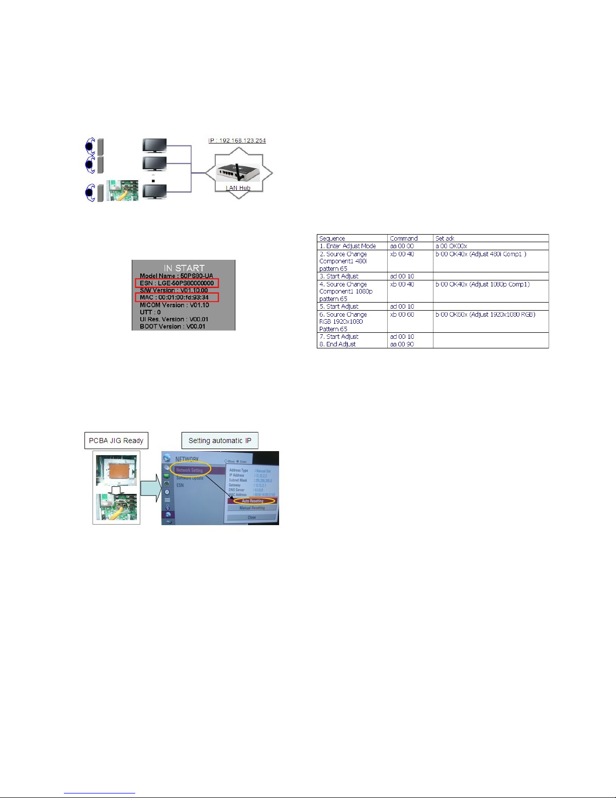
5. LAN PORT + ESN INSPECTION
5-1. Equipment & Condition
- Each other connection to LAN Port of IP Hub and Jig
5-2. MAC Address & ESN Key confirmation
- Push “IN-START” Key in service remote controller.
5-3. LAN PORT INSPECTION(PING TEST)
- LAN Port connection with PCB
- Network setting at MENU Mode of TV
- setting automatic IP
- Setting state confirmation
-> If automatic setting is finished, you confirm IP and MAC
Address.
- remove LAN CABLE
6. ADC adjustment
6-1. Overview
ADC adjustment is needed to find the optimum black level and
gain in Analog-to-Digital device and to compensate RGB
deviation.
6-2. Equipment & Condition
(1) Jig (RS-232C protocol)
(2). Internal pattern is used. No external signal is needed.
6-3. Adjustment
(1) Adj. protocol
(2) Check adjust device
Pattern Generator : (MSPG-925FA)
Adjust 480i Comp1
(MSPG-925FA:model :209 , pattern :65)
Adjust 1080p Comp1
(MSPG-925FA:model :225 , pattern :65)
Adjust RGB (MSPG-925FA:model :225 , pattern :65)
The PU02A have not ECHO.
7. EDID(The Extended Display
Identification Data) / DDC(Display
Data Channel) download
7-1. Overview
It is a VESA regulation. A PC or a MNT will display an optimal
resolution through information sharing without any necessity
of user input. It is a realization of °∞Plug and Play°±.
7-2. Equipment
- Adj. R/C
- Since embedded EDID data is used, EDID download jig,
HDMI cable and D-sub cable are not need.
7-3. Download method
(1) Press Adj. key On the Adj. R/C, press Adj. key then select
EDID D/L. By pressing Enter key, EDID download will
begin.
(2) If Download is successful, OK is displayed.
(3) If Download is a failure, NG is displayed.
(4) Re-try download
- 7 -
LGE Internal Use OnlyCopyright ©2011 LG Electronics Inc. All rights reserved.
Only for training and service purposes
Page 8
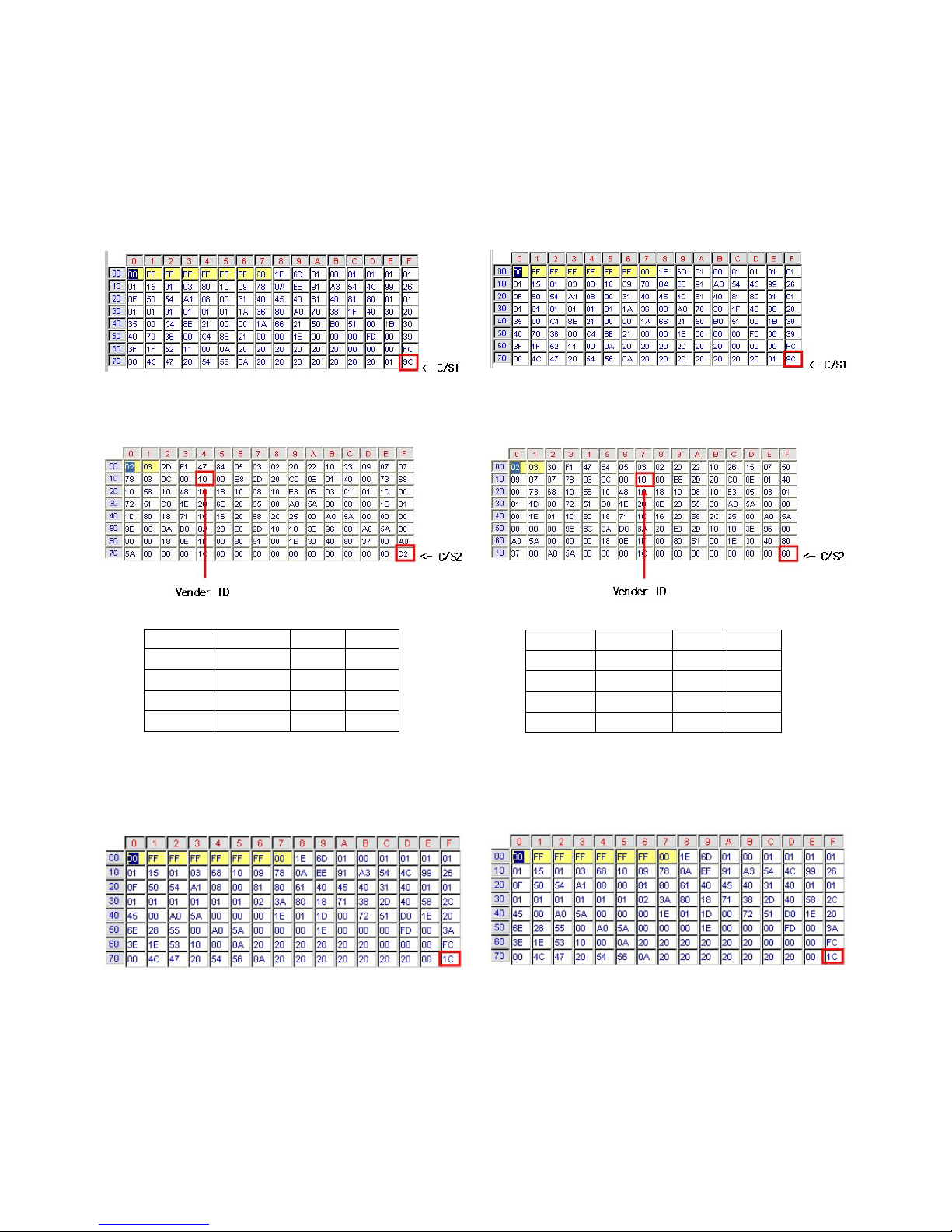
7-4. EDID DATA(PCM)
- Reference: Download is only possible in POWER ON
MODE.
- HDMI
EDID Block 0, Bytes 0-127 [00H-7FH]
Block Type: EDID 1.3
EDID Block 1, Bytes 128-255 [80H-FFH]
Block Type: CEA EDID Timing Extension Version 3
RGB [C/S: 1C]
EDID Block 0, Bytes 0-127 [00H-7FH]
Block Type: EDID 1.3
7-5. EDID DATA(AC-3)
- Reference: Download is only possible in POWER ON
MODE.
- HDMI
EDID Block 0, Bytes 0-127 [00H-7FH]
Block Type: EDID 1.3
EDID Block 1, Bytes 128-255 [80H-FFH]
Block Type: CEA EDID Timing Extension Version 3
RGB [C/S: 1C]
EDID Block 0, Bytes 0-127 [00H-7FH]
Block Type: EDID 1.3
- 8 -
LGE Internal Use OnlyCopyright ©2011 LG Electronics Inc. All rights reserved.
Only for training and service purposes
Vender ID C/S1 C/S2
HDMI1 10 9C D2
HDMI2 20 9C C2
HDMI3 30 9C B2
HDMI4 40 9C A2
Vender ID C/S1 C/S2
HDMI1 10 9C 60
HDMI2 20 9C 50
HDMI3 30 9C 40
HDMI4 40 9C 30
Page 9

8. White Balance adj.
8-1. Overview
(1) W/B adj.: Objective & How-it-works
1) Objective: To reduce each Panel’s W/B deviation
2) How-it-works: When R/G/B gain in the OSD is at 192, it
means the panel is at its Full Dynamic
Range. In order to prevent saturation of
Full Dynamic range and data, one of
R/G/B is fixed at 192, and the other two is
lowered to find the desired value.
8-2. Equipment
(1) Color Analyzer : CA-210 (NCG: CH 9 / WCG: CH12 /PDP
Module:CH10)
(2) Adj. Computer
(During auto adj., RS-232C protocol is needed)
(3) Adj. R/C
(4) Video Signal Generator MSPG-925F 720p/216Gray
(Model:217, Pattern:78)
-> Only when internal pattern is not available
- Color Analyzer Matrix should be calibrated using CS-1000
8-3. Equipment connection map
8-4. Adj. Command (Protocol)
O Protocol
<Command Format>
- LEN: Number of Data Byte to be send
- CMD: Command
- VAL: FOS Data
- CS: Checksum of sent Data
- A: Acknowledge
Ex) [Send: JA_00_DD] / [Ack: A_00_okDDX]
O RS-232C Command used during auto-adj.
Ex) wb 00 00 -> Begin white balance auto-adj.
wb 00 10 -> Gain adj.
ja 00 ff -> Adj. data
jb 00 c0
...
...
wb 00 1f -> Gain adj. complete
*(wb 00 20(Start), wb 00 2f(End)) -> Off-set adj.
wb 00 ff -> End white balance auto-adj.
8-5. Auto Adj. method
(1) Set TV in adj. mode using POWER On Key
(2) Zero calibrate probe then place it on the center of the
Display
(3) Connect Cable(RS-232C)
(4) Select mode in adj. Program and begin adj.
(5) When adj. is complete (OK Sign), check adj. status per
mode
(Warm, Medium, Cool)
(6) Remove probe and RS-232C cable to complete adj.
- Adj. must begin w/ command “wb 00 00”, and end “wb 00
ff” and adj. offset if needed.
- Offset adjust limit value.
Offset Min = 34 (Decimal)
Offset Max = 94 (Decimal)
8-6. Manual adj. method
Dynamic contrast : off
Dynamic color : off
OPC : Off
Energy saving mode : Off
(1) Set TV Picture Mode to Standard and in Advanced
Control, set Dynamic Contrast and Color ‘ Off ’ .
(2) Set TV in adj. mode using POWER On Key
(3) Press ADJ key -> EZ adjust using adj. R/C
(4) Using CH + / - KEY, select 10.TEST PATTERN then press
Enter to place in HEAT RUN mode and wait for 30
minutes.
(4) Zero calibrate the probe of Color Analyzer, then place it on
the center of LCD module within 10 cm of the surface.
(5) Press ADJ key -> 7. White-Balance then press the cursor
to the right (KEY
G)
(When
G is pressed Full White internal pattern will be
displayed)
(6) One of R Gain / G Gain / B Gain should be fixed at 192,
and the rest will be lowered to meet the desired value.
(7) Adj. is performed in COOL, MEDIUM, WARM 3 modes of
color temperature
(8) Off set Adjust in MEDIUM, WARM 2 modes of color
temperature ( Only THX Model )
V If internal pattern is not available, use HDMI input. In EZ
Adj. menu 7.White Balance, you can select one of 3
options: None, Inner, HDMI. Default is inner. By selecting
HDMI, you can adjust using HDMI signal.
- 9 -
LGE Internal Use OnlyCopyright ©2011 LG Electronics Inc. All rights reserved.
Only for training and service purposes
Model 100 Point WB mode WB Adj. Program
Non THX Model lists.
50PZ550-UA Only Adjust Medium Use Matrix
60PZ550-UA (Color Temperature) Adj. Program
50PZ540-UB mode RUN_Matrix_ADJ
60PZ540-UB ( Matrix Type )
Page 10
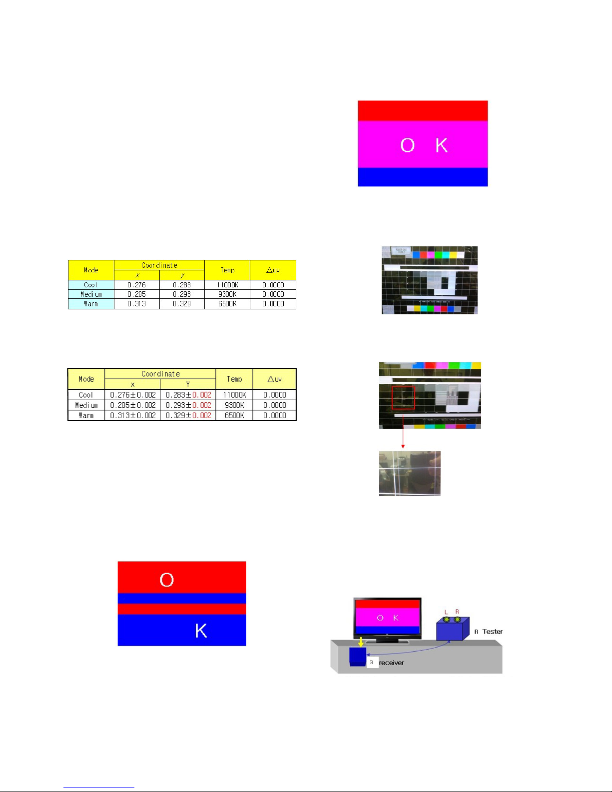
V Adj. condition and cautionary items
(1) Lighting condition in surrounding area
Surrounding lighting should be lower than 10 lux. Try
to isolate adj. area into dark surrounding.
(2) Probe location
- PDP : Color Analyzer (CA-100, CA-100+, CA210)
probe should be firmly attached to the Module
- LCD : Color Analyzer (CA-210) probe should be within
10cm and perpendicular of the module surface
(80°~ 100°)
- In case of LCD, B/L on should be checked using no
signal or Full white Pattern
8-7. Reference (White Balance adj.
coordinate and color temperature)
O Standard color coordinate and temperature using CS-1000
O Luminance: Full white 216 Gray
O Standard color coordinate and temperature using CA-210(CH
10)
- Gain color coordinate
O Pattern : Full white 216 Gray
9. 3D Function Test
9-1. 3D Pattern Inspection
(Pattern Generator MSHG-600 or MSPG-6100, HDMI mode
NO. 872 , pattern No. 83)
(1) Please input 3D test pattern like below
(2) When 3D entrance OSD is automatically displayed, Push
the OK key
(3) When took off 3D shutter glasses, Check whether viewing
the pattern like below picture)
9-2. 2D TO 3D CONVERT INSPECTION
(1) Input Combination Pattern like (Fig.1) in HDMI Input
(2) Enter the Swap Button(Yellow Color)
Check the separated line in the SET
* When you enter the swap button. Depth value is set to
Maximum value(20) automatically Worker has to enter the
ETC Key Before using the swap button
9-3. RF Glasses , 3D RF Emitter Check
* Power Only Mode
* MSHG-600 or MSPG-6100
- 10 -
LGE Internal Use OnlyCopyright ©2011 LG Electronics Inc. All rights reserved.
Only for training and service purposes
(Fig.1)
Page 11
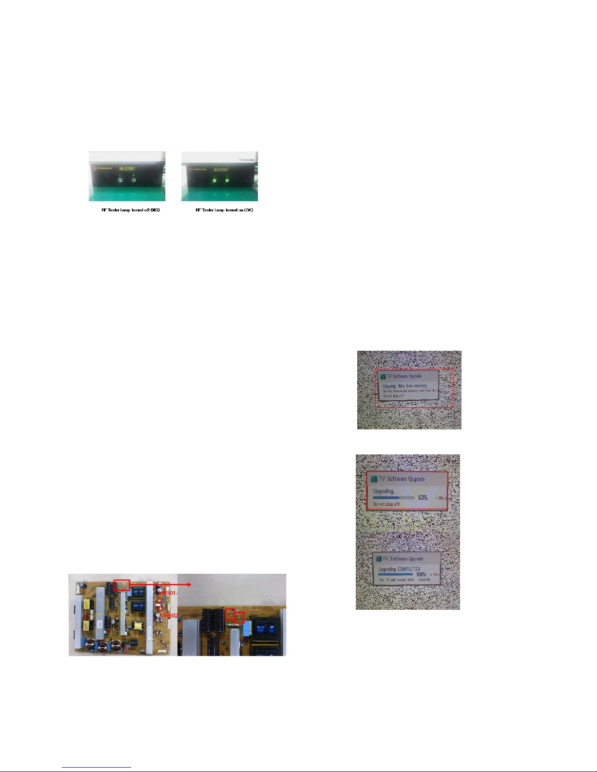
* Test Scenario
(1) Set TV in adj. mode using Power Only Key
(2) HDMI 1.4 Frame Packing 3D images are input to the 3D
Video Player
(3) Check the 3D Video Display.
(4) If RF emitter signal is correctly received to RFreceiver, the
lamp of RF tester turn on
10. Option selection per country
10-1. Overview
O Option selection is only done for models in Non-USA North
America due to rating
O Applied model: PU13A Chassis applied USA Model(Not
Canada, Mexico)
10-2. Method
(1) Press ADJ key on the Adj. R/C, then select Country Group
Menu
(2) Depending on destination, select KR or US, then on the
lower option, select US, CA, MX. Selection is done using
+, - KEY
10-3. Ship-out (Default) mode check
(Instop)
O After final inspection, press In-Stop key of the Adj. R/C and
check that the unit goes to Stand-by mode.
10-4. POWER Supply Unit PCB Ass'y Va/Vs
Voltage adjustment.
(1) Test equipment : D.M.M 1EA
(2) Connection Diagram for Measuring : refer to (Fig.1)
(3) Vs adjustment (refer fig.1)
1) Connect + terminal of D.M.M. to Vs pin of P811, connect
-terminal to GND pin of P811
2) After turning VR901, voltage of D.M.M adjustment as
same as Vs voltage which on label of panel left/top (
deviation ; ± 0.5V)
(4) Va adjustment (refer fig.1)
1) After receiving 100% Full White Pattern, HEAT RUN.
2) Connect + terminal of D.M.M. to Va pin of P811, connect
-terminal to GND pin of P811
- After turning VR502,voltage of D.M.M adjustment as
same as Va voltage which on label of panel left/top
(deviation; ± 0.5V)
11. USB Download (S/W Update,
*.epk File Download)
(1) Put the USB Stick to the USB socket
(2) Automatically detecting update file in USB Stick
- If your downloaded program version in USB Stick is Low,
it didn’t work.
But your downloaded version is High, USB data is
automatically detecting
(3) Show the message “Copying files from memory”
(4) Updating is staring.
(5) Updating Completed, The TV will restart automatically.
(6) If your TV is turned on, check your updated version and
Tool option. (explain the Tool option, next stage)
* If downloading version is more high than your TV have,
TV can lost all channel data. In this case, you have to
channel recover. if all channel data is cleared, you didn’t
have a DTV/ATV test on production line.
- 11 -
LGE Internal Use OnlyCopyright ©2011 LG Electronics Inc. All rights reserved.
Only for training and service purposes
(Fig.1)
Page 12
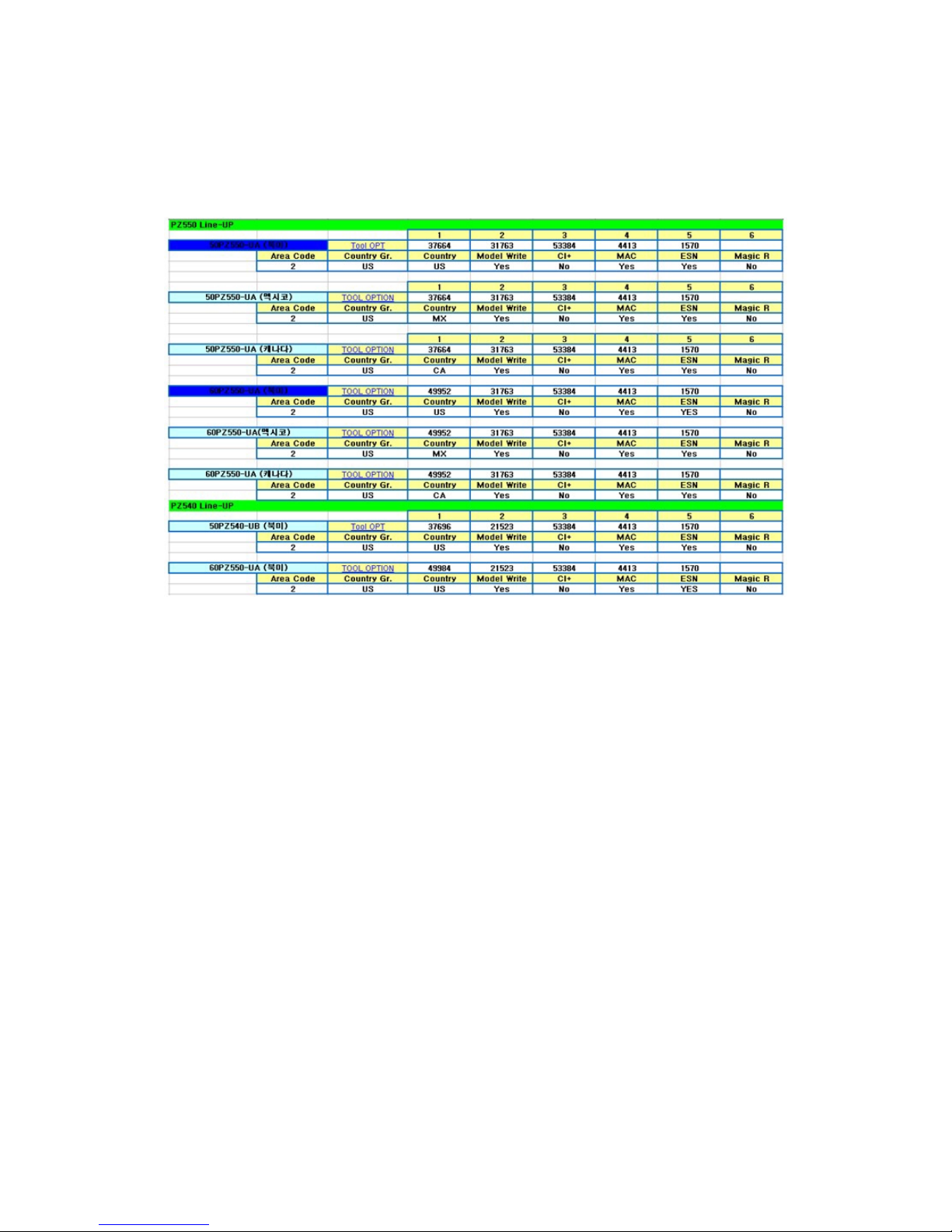
* After downloading, have to adjust TOOL OPTION again.
(1) Push "IN-START" key in service remote controller.
(2) Select "Tool Option 1" and Push “OK” button.
(3) Punch in the number. (Each model has their number.)
(4) Completed selecting Tool option.
- 12 -
LGE Internal Use OnlyCopyright ©2011 LG Electronics Inc. All rights reserved.
Only for training and service purposes
Page 13
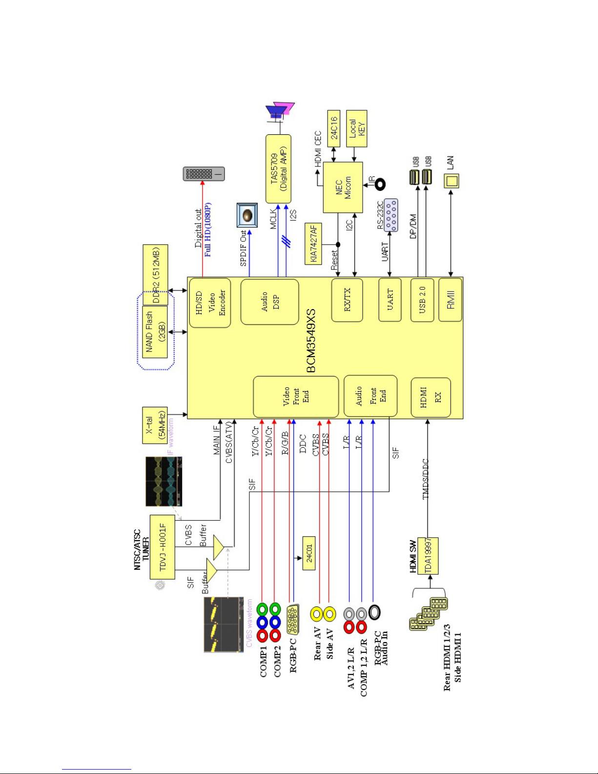
- 13 -
LGE Internal Use OnlyCopyright ©2011 LG Electronics Inc. All rights reserved.
Only for training and service purposes
BLOCK DIAGRAM
Page 14
- 14 -
LGE Internal Use Only
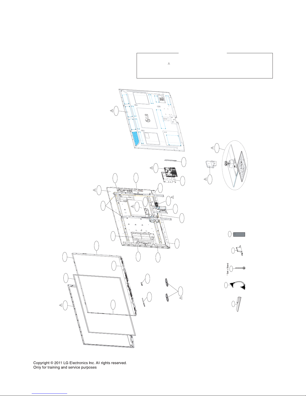
EXPLODED VIEW
590
200
400
520
300
305
301
602
202
203
501
205
209
207
208
240
601
303
304
302
580
910
900
120
206
204
201
570
560
Many electrical and mechanical parts in this chassis have special safety-related characteristics. These
parts are identified by in the Schematic Diagram and EXPLODED VIEW.
It is essential that these special safety parts should be replaced with the same components as
recommended in this manual to prevent X-RADIATION, Shock, Fire, or other Hazards.
Do not modify the original design without permission of manufacturer.
IMPORTANT SAFETY NOTICE
A10
LV1
A12
A4
A2
Page 15
Copyright © 2010 LG Electronics Inc. All rights reserved.
Only for training and service purposes
LGE Internal Use Only
Page 16
Copyright © 2010 LG Electronics Inc. All rights reserved.
Only for training and service purposes
LGE Internal Use Only
Page 17
Copyright © 2010 LG Electronics Inc. All rights reserved.
Only for training and service purposes
LGE Internal Use Only
Page 18
Copyright © 2010 LG Electronics Inc. All rights reserved.
Only for training and service purposes
LGE Internal Use Only
Page 19
Copyright © 2010 LG Electronics Inc. All rights reserved.
Only for training and service purposes
LGE Internal Use Only
Page 20
Copyright © 2010 LG Electronics Inc. All rights reserved.
Only for training and service purposes
LGE Internal Use Only
Page 21
Copyright © 2010 LG Electronics Inc. All rights reserved.
Only for training and service purposes
LGE Internal Use Only
Page 22
Copyright © 2010 LG Electronics Inc. All rights reserved.
Only for training and service purposes
LGE Internal Use Only
Page 23
Copyright © 2010 LG Electronics Inc. All rights reserved.
Only for training and service purposes
LGE Internal Use Only
Page 24
Copyright © 2010 LG Electronics Inc. All rights reserved.
Only for training and service purposes
LGE Internal Use Only
Page 25
Copyright © 2010 LG Electronics Inc. All rights reserved.
Only for training and service purposes
LGE Internal Use Only
Page 26
Copyright © 2010 LG Electronics Inc. All rights reserved.
Only for training and service purposes
LGE Internal Use Only
Page 27
Copyright © 2010 LG Electronics Inc. All rights reserved.
Only for training and service purposes
LGE Internal Use Only
Page 28
Copyright © 2010 LG Electronics Inc. All rights reserved.
Only for training and service purposes
LGE Internal Use Only
Page 29
Copyright © 2010 LG Electronics Inc. All rights reserved.
Only for training and service purposes
LGE Internal Use Only
Page 30
Page 31
Great Company Great People
GP2R_BCM (PU13A) Training manual
GP2R_BCM (PU13A) Training manual
Contents
-Block Diagram
Great Company Great People
2010.12.03
- Power Flow Diagram
PDP ATSC Gr. LEE SANG WON
- Trouble Shooting Guide
Page 32
Great Company Great People
Trouble Shooting Guide for LG Service Man
Trouble Shooting Guide for LG Service Man
5/37
PU13A Model Lists
-50PZ550-UA , 60PZ550-UA
-50PZ540-UB , 60PZ540-UB
Page 33
Great Company Great People
6/37
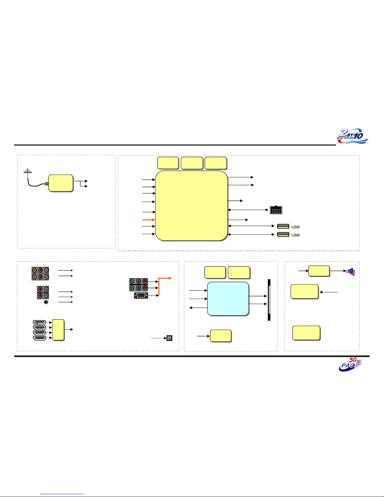
Block Diagram – Over view
DDR2
512MB
533MHz
DDR2
512MB
533MHz
BCM3549XSP_3D_PIP
(400MHz)
BCM3549XSP_3D_PIP
(400MHz)
1080P
LVDS
(External Input/Output)
EXT_IN
HDMI
CVBS1,2
CVBS1/
SIF_LIVE
ATSC/ NTSC
LGIT
TDVJ-H101F
IF
BCM_I2S
Audio_AMP
TAS5709
Audio_AMP
TAS5709
CVBS1/LR
CVBS2/LR
COMP1_LR
COMP2_LR
RGB_LR
EXT_IN
HDMI
NAND
4Gbit
NAND
4Gbit
Ethernet
(Etc)
USB2
SPDIF
SIF_LIVE
LR1,2
IF
BCM_I2S
USB1
COMP1/2
HDMI 1.3 x 4
RGB
4:1 Switch
NXP19997
NEC Micom
uPD
NEC Micom
uPD
BCM_SPDIF
BCM_SPDIF
COMP_LR1,2
RGB_LR
LAN
LG8300_3DF_ASIC
LG8300_3DF_ASIC
(3DF_Block)
1080P
1080P(L)
1080P(R)
DDR2
256Mb
400MHz
DDR2
256Mb
400MHz
Serial Flash
2Mbit
Serial Flash
2Mbit
3D_Sync_Out
3D_Sync_Out
RF_Tx
RF_Tx
L/R Indicator
GPIO24
L/R Indicator
X-TAL
54MHz
X-TAL
54MHz
Wireless
Interface
Wireless
Interface
CEC Control
Page 34
Great Company Great People
6/37
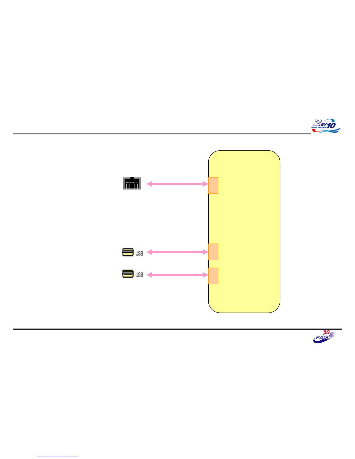
Block Diagram – USB , Ethernet
BCM3549XSP_3D_PIP
USB1 DP/DN
USB_1_DP/DM2
Ethernet
EPHY TX/RX
LAN
USB_2_DP/DM2
USB2 DP/DN
Page 35
Great Company Great People
6/37
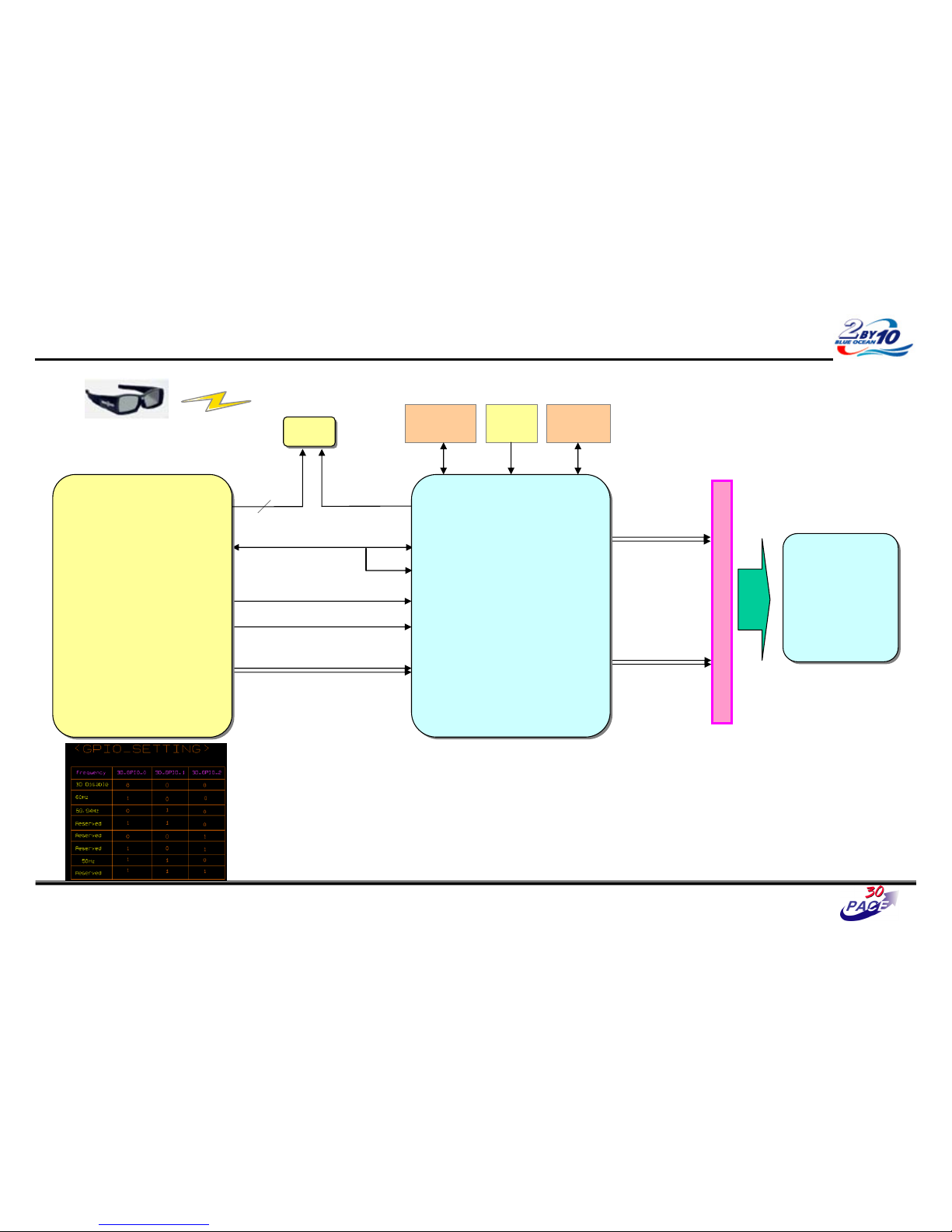
Block Diagram – 3DF Block Diagram
I2C
L/R DETECT
3DF_ASIC RESET
LVDS 2Ch
DDR2
(256Mbit)
3D :
1920x1080/60Hz
(S/S, T/B, C/B, F/S)
1920x1080/48Hz
(F/S)
X-tal
(25MHz)
Serial_Flash
(2Mbit)
LVDS 2Ch
Left (2D):
1920x1080/60Hz
LVDS ( 80Pin )
LVDS 2Ch
3D_SYNC_OUT
■ Processing
LVDS-Rx , Dual Link 10 bit (25~85MHz)
LVDS-Tx , Quad Link 10 bit (25~85MHz)
DDR2-PHY : 333MHz (Max.350MHz)
(DDR2 x16 1ea, 512Mb/256Mb)
GPIO#32
BCM3549_XSP
(3D_PIP)
BCM3549_XSP
(3D_PIP)
3DF_ASIC
LG8300
3DF_ASIC
LG8300
PDP
PDP
3D_SYNC
EMITTER_PULSE
Right :
1920x1080/60Hz
1920x1080
60Hz
PO_RST_N
GPIO[2]
I2C
I2C_M
RF_Tx
RF_Tx
RF_Shutter_Glasses
3D_GPIO
3
Page 36
Great Company Great People
6/37
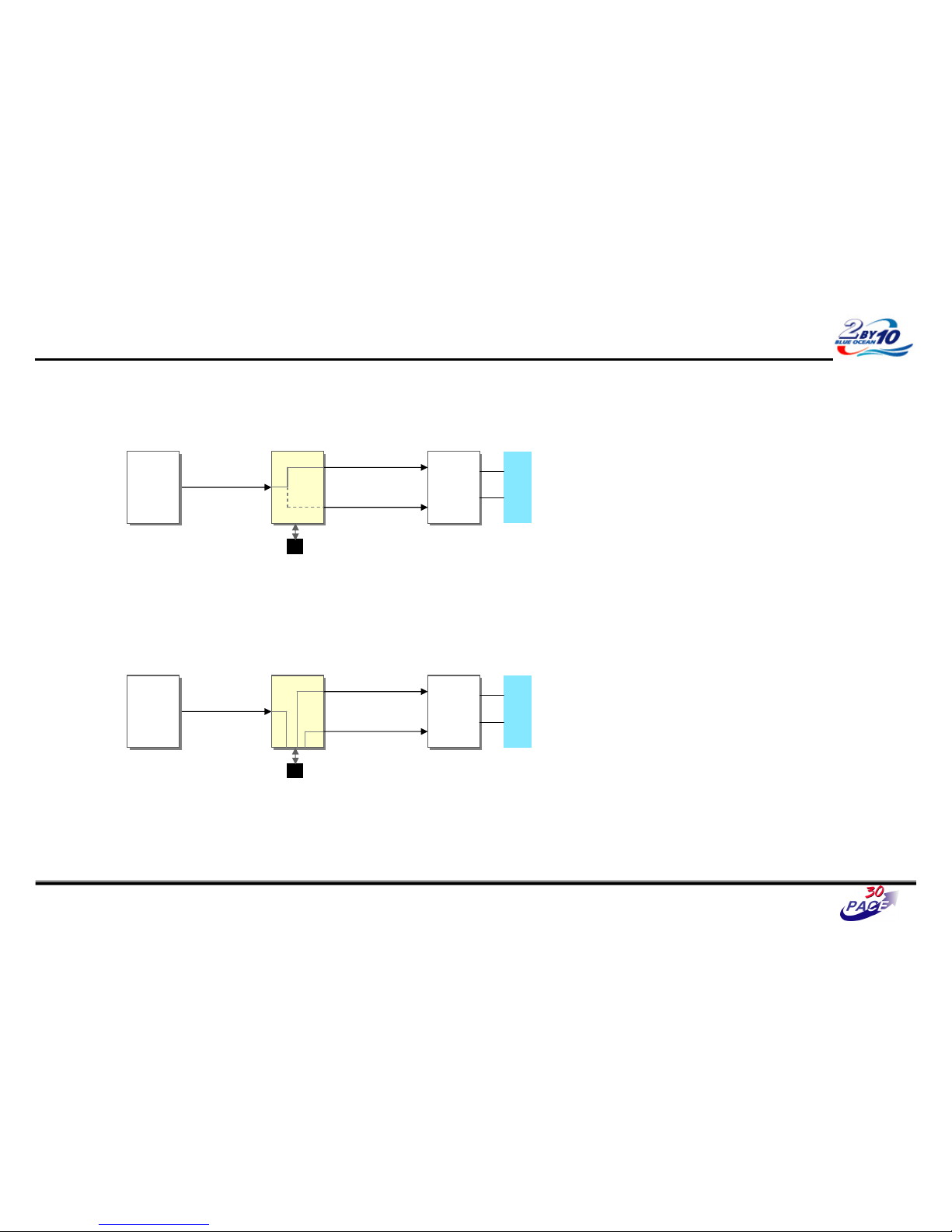
3D Block Operation , FHD Display
2D Mode
- Direct Bypass
1920x1080
60Hz
PDP
DTV SoC
DTV SoC
LG8300
LG8300
PDP
Controller
PDP
Controller
3D Mode
- Scaling & Formatting
2D :
1920x1080/60Hz
LVDS 2Ch
LVDS 2Ch
1920x1080
60Hz
PDP
DTV SoC
DTV SoC
LG8300
LG8300
PDP
Controller
PDP
Controller
3D :
1920x1080/60Hz
(S/S, T/B, C/B, F/S)
1920x1080/48Hz
(F/S)
LVDS 2Ch
2D : 1920x1080/60Hz
Left :
1920x1080/60Hz
LVDS 2Ch
Right :
1920x1080/60Hz
LVDS 2Ch
Page 37
Great Company Great People
6/37
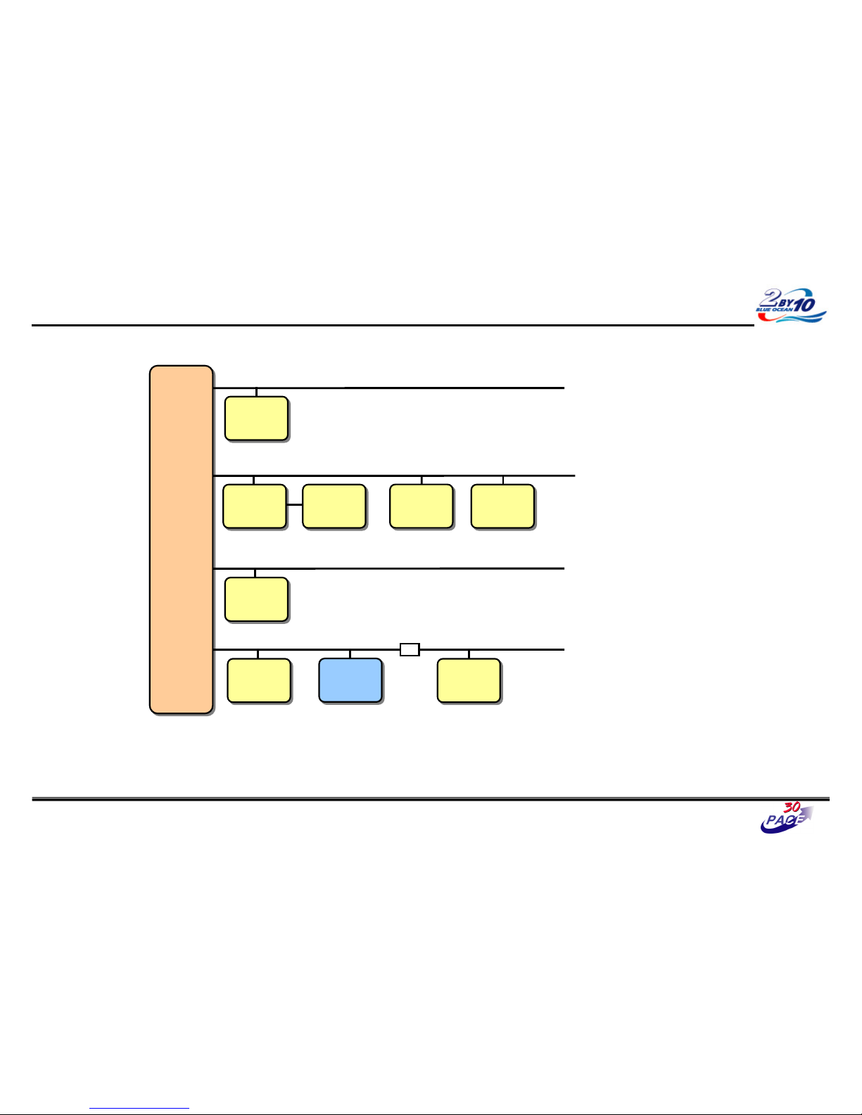
I2C MAP
BCM3549
BCM3549
CH2
CH3
CH1
Tuner
0xC2
Tuner
0xC2
EEPROM
24M01
0xA0
EEPROM
24M01
0xA0
EyeQ Green
R:0x20-22
G:0x70-72
B:0x90-92
EyeQ Green
R:0x20-22
G:0x70-72
B:0x90-92
Micom
uPD78F0513
0x52
Micom
uPD78F0513
0x52
CH4
Audio AMP
TAS5709
0x36
Audio AMP
TAS5709
0x36
HDMI S/W
TDA9997
0xC0
HDMI S/W
TDA9997
0xC0
PDP_Module
50R3
0x1C
PDP_Module
50R3
0x1C
Wireless
0x20
Wireless
0x20
3DF_ASIC
LG8300
0x3C
3DF_ASIC
LG8300
0x3C
Level Shift
Page 38
Great Company Great People
6/37
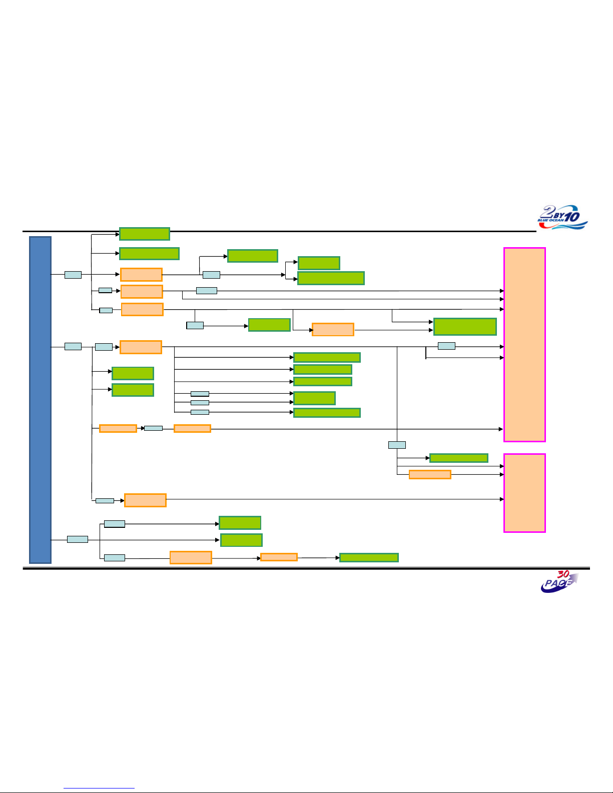
Power Rail
P
O
w
E
R
B
O
A
R
D
+5V
IC405
(TPS54418)
D1.2V
IC603,604,605,606
(DDR3)
IC100
BCM3549
+5V_ST
IC103
(RGB EEPROM)
D1.8V
L414
L413
A1.2V
IC400
(AP2121)
L413
+3.3V_ST +3.3V_NEC_ST
L415
IC701
NEC MICOM
IC700
NEC MICOM EEPROM
IC401
(TPS54319)
+1.8V_HDMI
L201
IC200
HDMI S/W
IC402
(AOZ1024)
+3.3V
L411
D3.3V
L302
L303
+3.3V_AU_AVDD
+3.3V_DVDD
IC300
AUDIO AMP
L801
+3.3V_HDMI
IC200(HDMI S/W)
IC500(NAND Flash)
IC705(NVRAM)
TU600(TUNER)
A2.5V
D1.2V
D1.8V
D3.3V
+7V_TU
P_17V
L403
IC300
AUDIO AMP
IC404
(TPS54231)
TU1400(TUNER)
IC1101
(USB OCP IC)
IC1102
(USB OCP IC)
L405
0.29A
3.08A
0.28A
0.23A
0.97A
IC406(LDO)
+5V_TU
L402
IC702
(RS-232C Rec.)
IC704
(RS-232C SW
IC602
(BD35331)
DDR_VREF
L416
L407
Wireless
L1300
L419
IC1500
LG8300
IC1502(Serial_Flash)
L420
L1500
IC1700
(AOZ1072)
IC1703(LDO)
3V3
1V8
1V0
IC502(LDO)Q801
Page 39
Great Company Great People
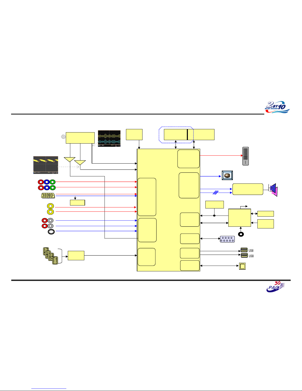
Power-Up Boot Fail Trouble Shooting
8/37
CVBS waveform
IF waveform
TAS5709
(Digital AMP)
Reset
I2S
BCM3549XS
MCLK
HDMI CEC
IR
CVBS
Buffer
SIF
Buffer
RS-232C
I2C
CVBS(ATV)
NTSC/ATSC
TUNER
X-tal
(54MHz)
NAND Flash
(2GB)
DDR2 (512MB)
TDVJ-H001F
KIA7427AF
KIA7427AF
24C16
24C16
Local
Local
KEY
KEY
MAIN IF
DP/DM
DP/DM
NEC
NEC
Micom
Micom
COMP1
COMP2
Y/Cb/Cr
Y/Cb/Cr
R/G/B
RGB-PC
Rear AV
CVBS
Side AV
CVBS
AV1,2 L/R
COMP 1,2 L/R
L/R
L/R
RGB-PC
Audio In
Rear HDMI 1/2/3
Side HDMI 1
SIF
Audio
Front
End
Video
Front
End
TMDS/DDC
HDMI
RX
Digital out
Full HD(1080P)
HD/SD
Video
Encoder
Audio
DSP
SPDIF Out
UART
RX/TX
UART
UART
USB 2.0
RMII
RMII
24C01
DDC
SIF
TDA19997
TDA19997
HDMI SW
LAN
LAN
Page 40
Great Company Great People
Power-Up Boot Fail Trouble Shooting
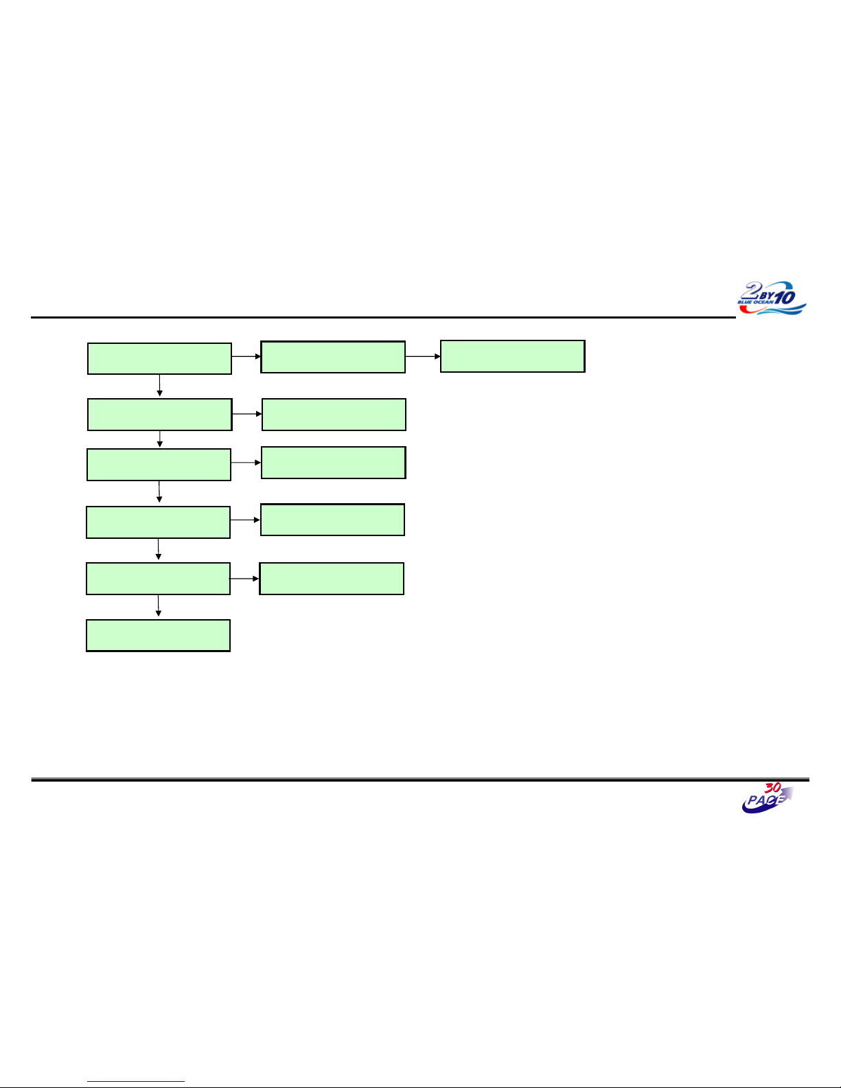
Check P400 All
Voltage Level (ST_5V)
Check Power connector
OK ?
Replace Power board
Y
NY
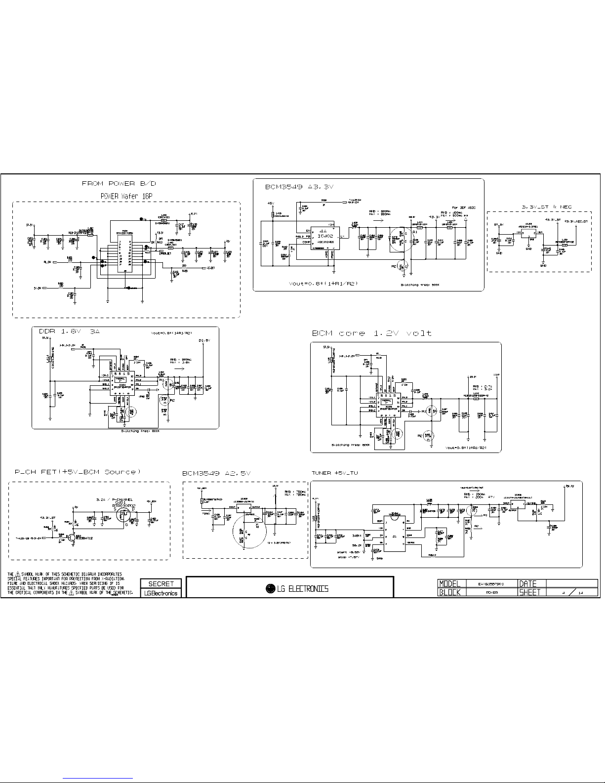
Check L412
Voltage Level 1.2V
Replace IC405
Y
N
Check IC403 (pin2)
Voltage Level 2.5V
Replace IC403
Y
N
Check L411
Voltage Level 3.3V
Check L402 (pin3) Output
Voltage Level (ST_5V)
Replace L402
N
Y
7/37
Replace IC402
N
Y
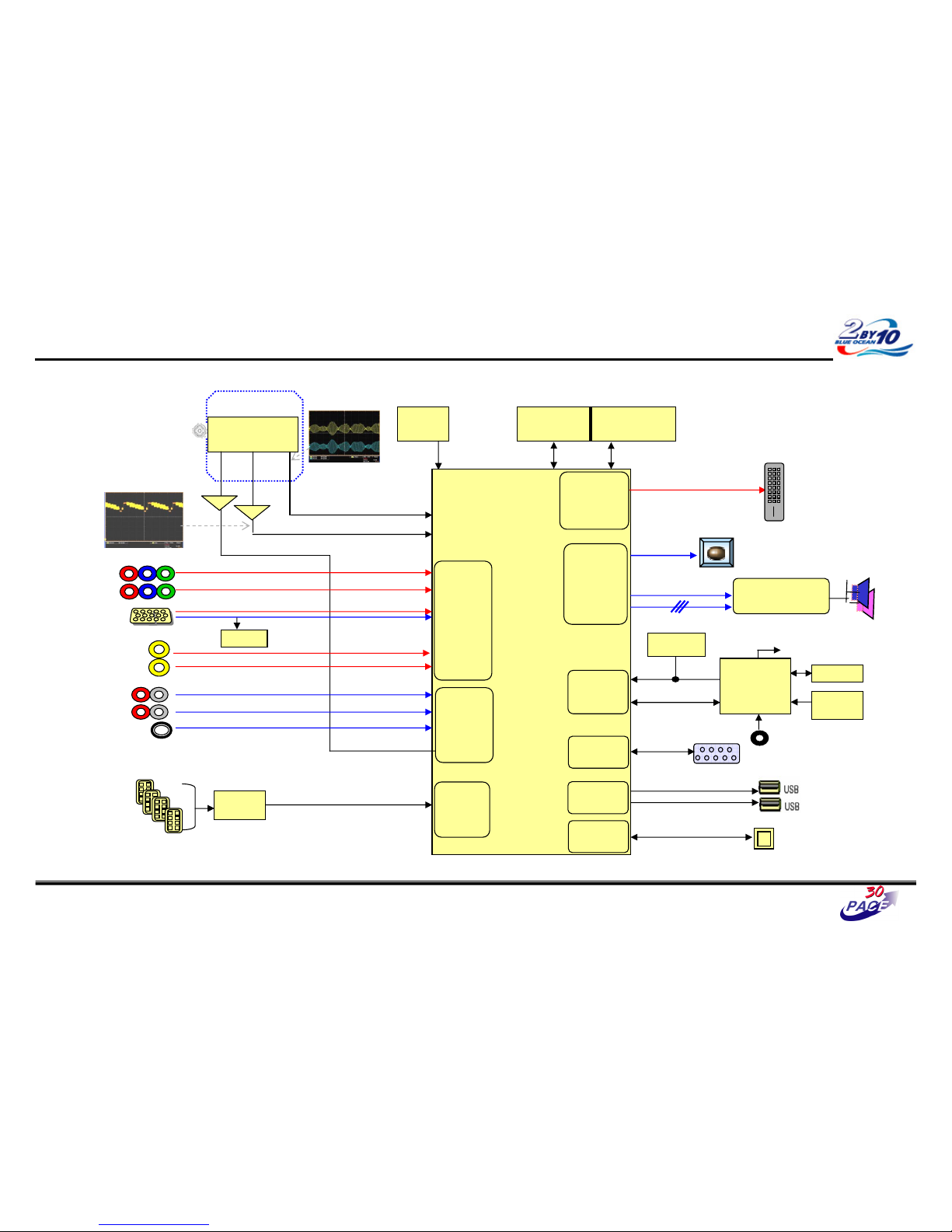
Replace IC501
Page 41
Great Company Great People
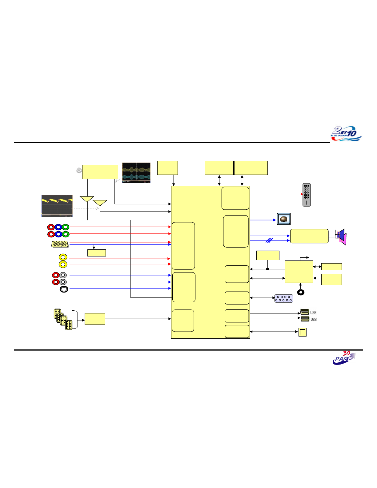
No OSD Trouble Shooting
8/37
CVBS waveform
IF waveform
TAS5709
(Digital AMP)
Reset
I2S
BCM3549XS
MCLK
HDMI CEC
IR
CVBS
Buffer
SIF
Buffer
RS-232C
I2C
CVBS(ATV)
NTSC/ATSC
TUNER
X-tal
(54MHz)
NAND Flash
(2GB)
DDR2 (512MB)
TDVJ-H001F
KIA7427AF
KIA7427AF
24C16
24C16
Local
Local
KEY
KEY
MAIN IF
DP/DM
DP/DM
NEC
NEC
Micom
Micom
COMP1
COMP2
Y/Cb/Cr
Y/Cb/Cr
R/G/B
RGB-PC
Rear AV
CVBS
Side AV
CVBS
AV1,2 L/R
COMP 1,2 L/R
L/R
L/R
RGB-PC
Audio In
Rear HDMI 1/2/3
Side HDMI 1
SIF
Audio
Front
End
Video
Front
End
TMDS/DDC
HDMI
RX
Digital out
Full HD(1080P)
HD/SD
Video
Encoder
Audio
DSP
SPDIF Out
UART
RX/TX
UART
UART
USB 2.0
RMII
RMII
24C01
DDC
SIF
TDA19997
TDA19997
HDMI SW
LAN
LAN
Page 42
Great Company Great People
No OSD Trouble Shooting
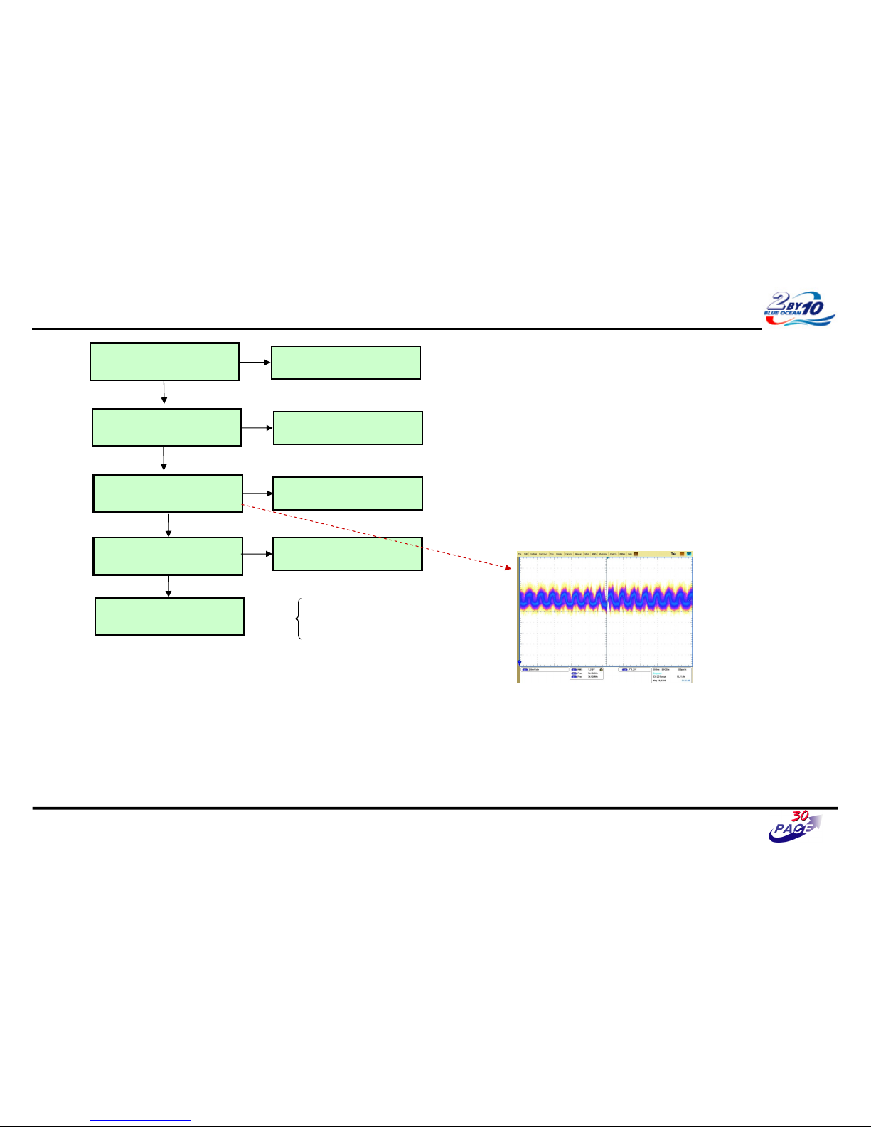
Check P1500
#33(TXAC-) , #32(TXAC+) ,
#17(TXBC-) , #16(TXBC+)
Maybe BCM has problems
Replace IC501
Check LVDS Cable for damage or
open conductors.
Check PDP Module
Control board
Refer to Module CAS
Y
N
Y
Replace Cable
N
Y
Check SMPS Vs,Va, 5V,17V
Replace Power Board
N
Check P400
5V_ON
Check GPIO Path of IC701
N
Y
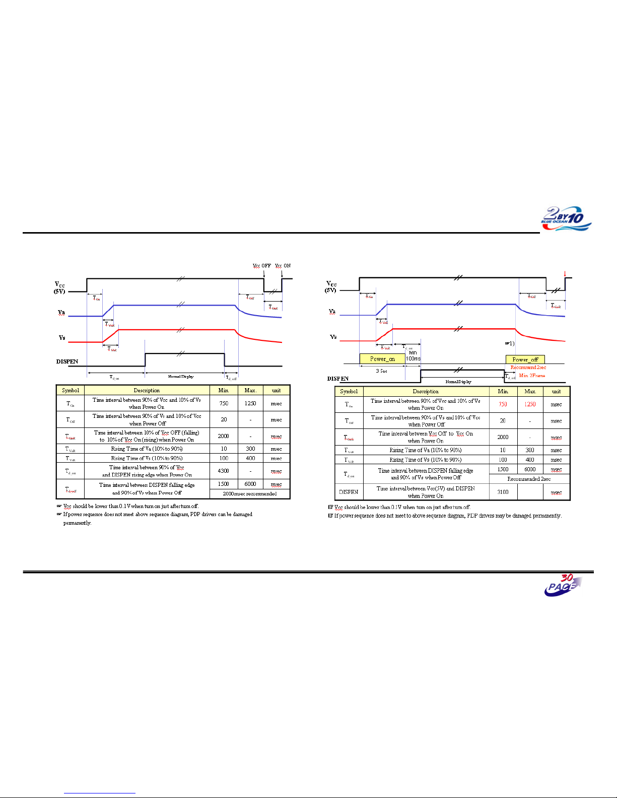
Electrical Specifications
Power Supply Sequence
Input Signal Timing Specification
Control Signal Register
Check CAS
It should satisfy the Pixel Clock on CAS.
9/37
Page 43
Great Company Great People
No OSD Trouble Shooting (Module Power Sequence)
< 50R3 >
10/37
< 60R3 >
Page 44
Great Company Great People
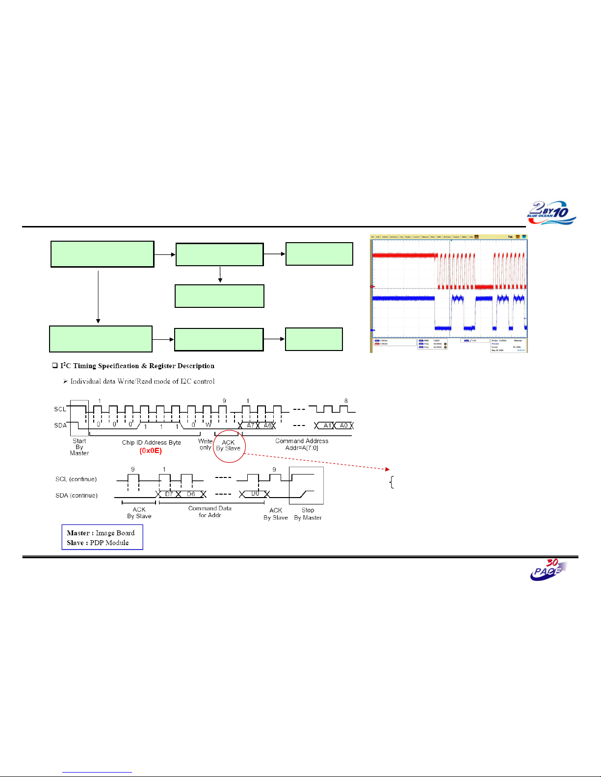
Module Control Trouble Shooting
“TILT” on Adjust Remocon
: PDP internal pattern displays?
PDP Module Power is OK?
N
PDP Module is OK.
Check P1500 SCL,SDA line SCL,SD
A line #75 , #77
Check Signal
: X900 output
N
Y
< Sample Signal on R2717, R2703 >
SCL
SDA
ACK signal Check
Low : OK
High : Error
Replace X900
N
Check SMPS & cable
N
Y
Replace PDP Module
11/37
Page 45
Great Company Great People
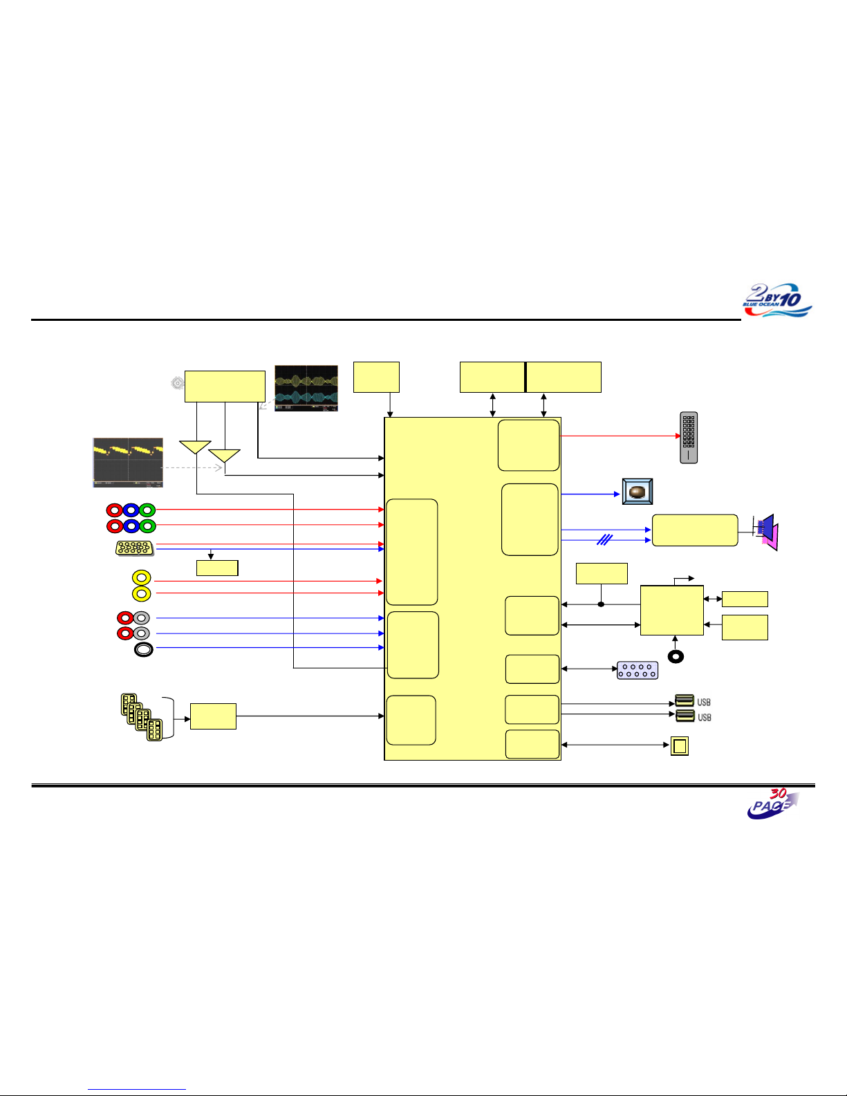
Digital TV Video Trouble Shooting
12/37
CVBS waveform
IF waveform
TAS5709
(Digital AMP)
Reset
I2S
BCM3549XS
MCLK
HDMI CEC
IR
CVBS
Buffer
SIF
Buffer
RS-232C
I2C
CVBS(ATV)
NTSC/ATSC
TUNER
X-tal
(54MHz)
NAND Flash
(2GB)
DDR2 (512MB)
TDVJ-H001F
KIA7427AF
KIA7427AF
24C16
24C16
Local
Local
KEY
KEY
MAIN IF
DP/DM
DP/DM
NEC
NEC
Micom
Micom
COMP1
COMP2
Y/Cb/Cr
Y/Cb/Cr
R/G/B
RGB-PC
Rear AV
CVBS
Side AV
CVBS
AV1,2 L/R
COMP 1,2 L/R
L/R
L/R
RGB-PC
Audio In
Rear HDMI 1/2/3
Side HDMI 1
SIF
Audio
Front
End
Video
Front
End
TMDS/DDC
HDMI
RX
Digital out
Full HD(1080P)
HD/SD
Video
Encoder
Audio
DSP
SPDIF Out
UART
RX/TX
UART
UART
USB 2.0
RMII
RMII
24C01
DDC
SIF
TDA19997
TDA19997
HDMI SW
LAN
LAN
Page 46
Great Company Great People
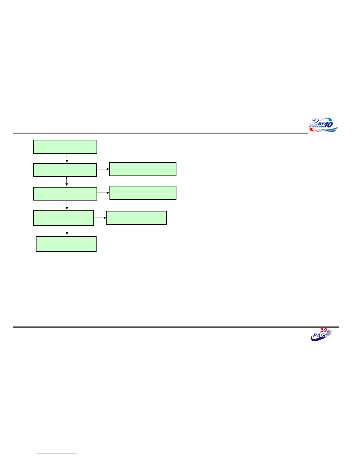
Digital TV Video Trouble Shooting
Check RF Cable
Y
Check Tuner 5V,7V Power
IC404(7V),IC406(5V)
Replace IC404 or IC406
Y
N
Y
Check IF_P,IF_N
R1412, R1413
Maybe Tuner has problems
: Replace Tuner
Y
Check PDP Module
Control board
Refer to Module CAS
13/37
N
Check 1500
#33(TXAC-) , #32(TXAC+) ,
#17(TXBC-) , #16(TXBC+)
Maybe BCM has problems
Replace IC501
N
Page 47
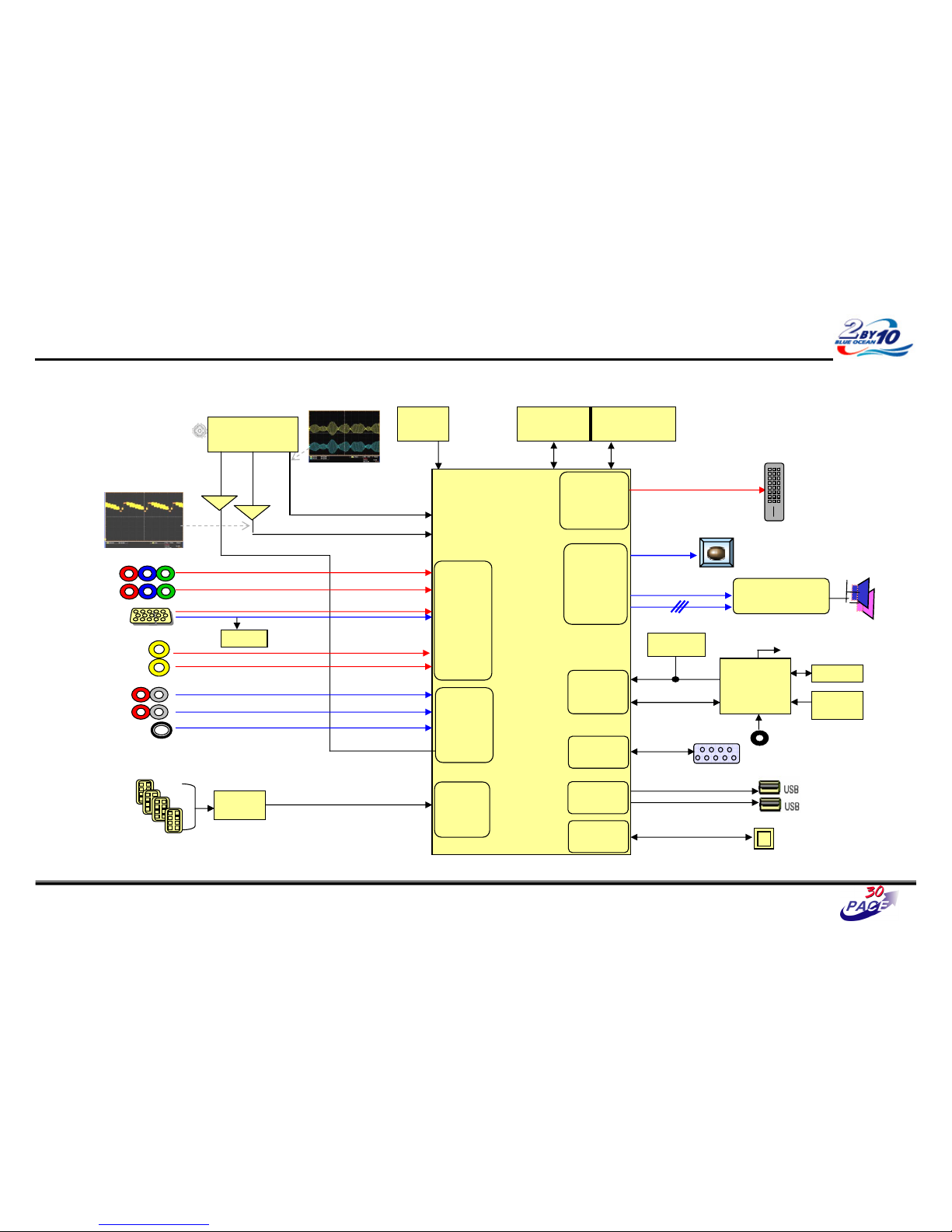
Great Company Great People
Analog TV Video Trouble Shooting
14/37
CVBS waveform
IF waveform
TAS5709
(Digital AMP)
Reset
I2S
BCM3549XS
MCLK
HDMI CEC
IR
CVBS
Buffer
SIF
Buffer
RS-232C
I2C
CVBS(ATV)
NTSC/ATSC
TUNER
X-tal
(54MHz)
NAND Flash
(2GB)
DDR2 (512MB)
TDVJ-H001F
KIA7427AF
KIA7427AF
24C16
24C16
Local
Local
KEY
KEY
MAIN IF
DP/DM
DP/DM
NEC
NEC
Micom
Micom
COMP1
COMP2
Y/Cb/Cr
Y/Cb/Cr
R/G/B
RGB-PC
Rear AV
CVBS
Side AV
CVBS
AV1,2 L/R
COMP 1,2 L/R
L/R
L/R
RGB-PC
Audio In
Rear HDMI 1/2/3
Side HDMI 1
SIF
Audio
Front
End
Video
Front
End
TMDS/DDC
HDMI
RX
Digital out
Full HD(1080P)
HD/SD
Video
Encoder
Audio
DSP
SPDIF Out
UART
RX/TX
UART
UART
USB 2.0
RMII
RMII
24C01
DDC
SIF
TDA19997
TDA19997
HDMI SW
LAN
LAN
Page 48
Great Company Great People
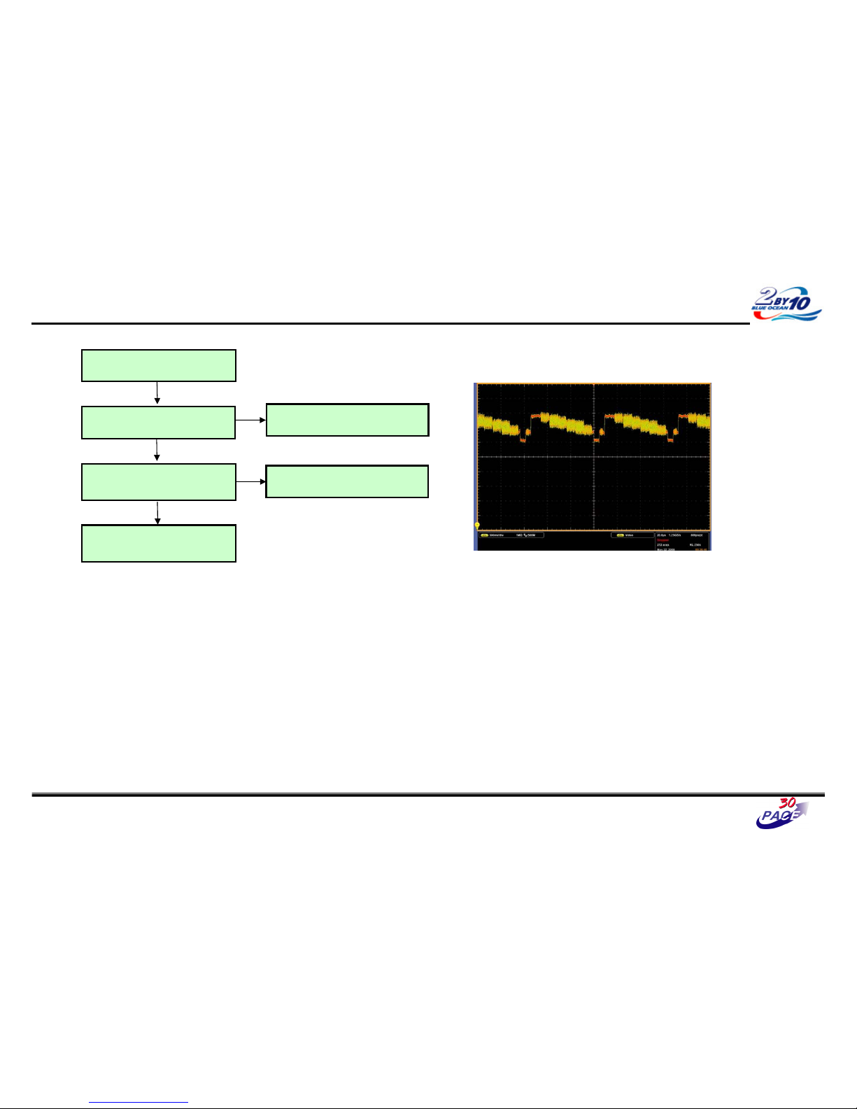
Analog TV Video Trouble Shooting
Check RF Cable
Check CVBS signal
TU1400 #11 Pin
Replace Tuner(TU1400)
Y
N
Check Tuner 5V,7V Power
IC404(7V),IC406(5V)
Replace IC404 or IC406
Y
N
Y
Replace BCM3549XS(IC501)
< CVBS waveform – sample >
- Defend on the input signal.
15/37
Page 49
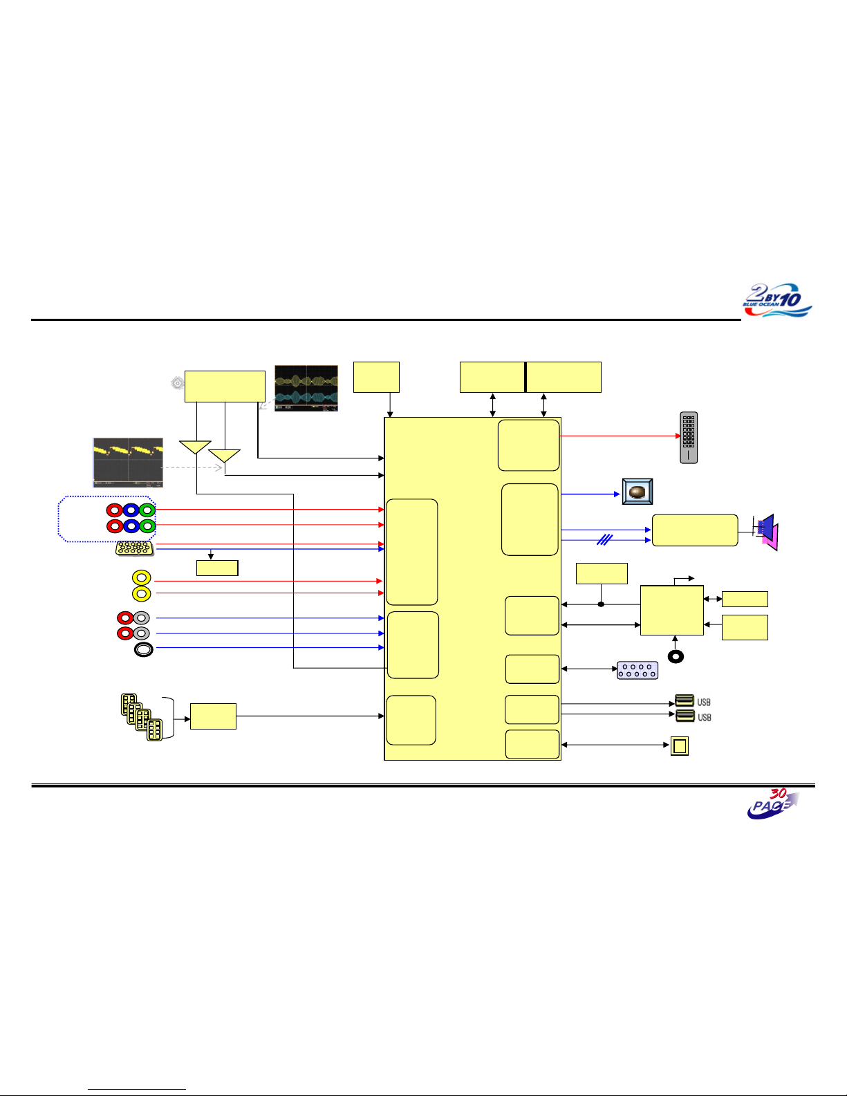
Great Company Great People
Component Video Trouble Shooting
16/37
CVBS waveform
IF waveform
TAS5709
(Digital AMP)
Reset
I2S
BCM3549XS
MCLK
HDMI CEC
IR
CVBS
Buffer
SIF
Buffer
RS-232C
I2C
CVBS(ATV)
NTSC/ATSC
TUNER
X-tal
(54MHz)
NAND Flash
(2GB)
DDR2 (512MB)
TDVJ-H001F
KIA7427AF
KIA7427AF
24C16
24C16
Local
Local
KEY
KEY
MAIN IF
DP/DM
DP/DM
NEC
NEC
Micom
Micom
COMP1
COMP2
Y/Cb/Cr
Y/Cb/Cr
R/G/B
RGB-PC
Rear AV
CVBS
Side AV
CVBS
AV1,2 L/R
COMP 1,2 L/R
L/R
L/R
RGB-PC
Audio In
Rear HDMI 1/2/3
Side HDMI 1
SIF
Audio
Front
End
Video
Front
End
TMDS/DDC
HDMI
RX
Digital out
Full HD(1080P)
HD/SD
Video
Encoder
Audio
DSP
SPDIF Out
UART
RX/TX
UART
UART
USB 2.0
RMII
RMII
24C01
DDC
SIF
TDA19997
TDA19997
HDMI SW
LAN
LAN
Page 50
Great Company Great People
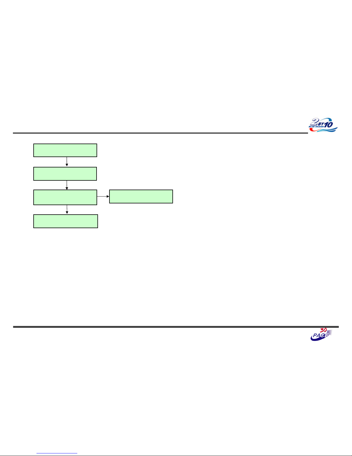
Component Video Trouble Shooting
Check input signal format
Is it supported?
Check signal
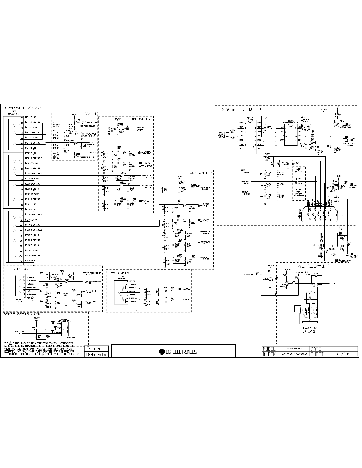
L100~L105
Y
Check the damage of JK100
And Replace Connector
N
Y
Replace BCM3549XS(IC501)
Y
Check Component Cable
※ Measured signals depend on the input signal.
17/37
Page 51
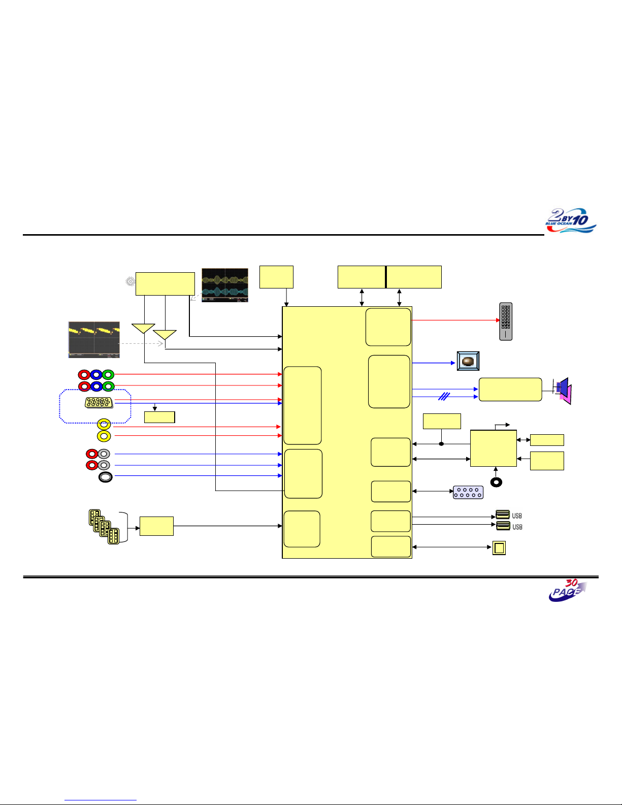
Great Company Great People
RGB Video Trouble Shooting
18/37
CVBS waveform
IF waveform
TAS5709
(Digital AMP)
Reset
I2S
BCM3549XS
MCLK
HDMI CEC
IR
CVBS
Buffer
SIF
Buffer
RS-232C
I2C
CVBS(ATV)
NTSC/ATSC
TUNER
X-tal
(54MHz)
NAND Flash
(2GB)
DDR2 (512MB)
TDVJ-H001F
KIA7427AF
KIA7427AF
24C16
24C16
Local
Local
KEY
KEY
MAIN IF
DP/DM
DP/DM
NEC
NEC
Micom
Micom
COMP1
COMP2
Y/Cb/Cr
Y/Cb/Cr
R/G/B
RGB-PC
Rear AV
CVBS
Side AV
CVBS
AV1,2 L/R
COMP 1,2 L/R
L/R
L/R
RGB-PC
Audio In
Rear HDMI 1/2/3
Side HDMI 1
SIF
Audio
Front
End
Video
Front
End
TMDS/DDC
HDMI
RX
Digital out
Full HD(1080P)
HD/SD
Video
Encoder
Audio
DSP
SPDIF Out
UART
RX/TX
UART
UART
USB 2.0
RMII
RMII
24C01
DDC
SIF
TDA19997
TDA19997
HDMI SW
LAN
LAN
Page 52
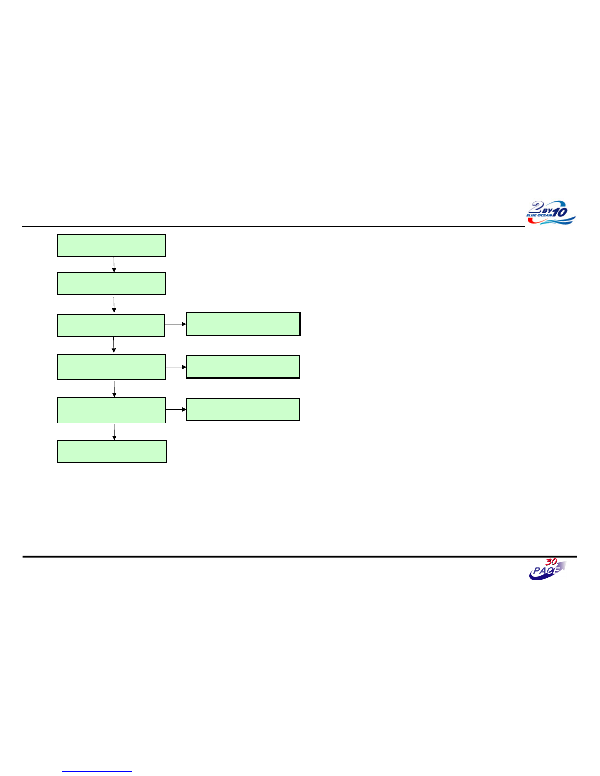
Great Company Great People
RGB Video Trouble Shooting
Check input signal format
Is it supported?
Check signal, Hsync, Vsync
R135, R136
Replace R135, R136.
Check signal
R137~R139
Y
N
Check P100
Replace connector (P100).
Y
N
Y
Replace R137~R139
N
Replace BCM3549XS(IC501)
Y
Check RGB Cable conductors for
damage
Y
※ Measured signals depend on the input signal.
19/37
Page 53
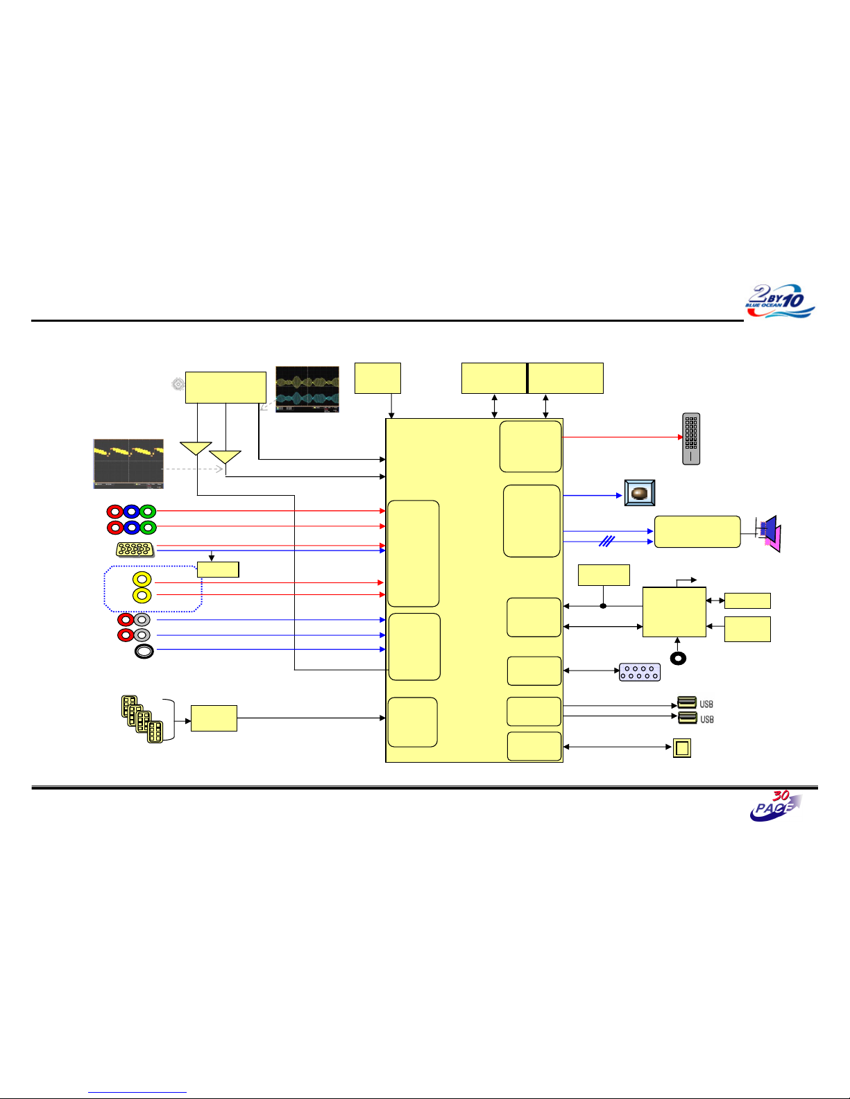
Great Company Great People
AV Video Trouble Shooting
20/37
CVBS waveform
IF waveform
TAS5709
(Digital AMP)
Reset
I2S
BCM3549XS
MCLK
HDMI CEC
IR
CVBS
Buffer
SIF
Buffer
RS-232C
I2C
CVBS(ATV)
NTSC/ATSC
TUNER
X-tal
(54MHz)
NAND Flash
(2GB)
DDR2 (512MB)
TDVJ-H001F
KIA7427AF
KIA7427AF
24C16
24C16
Local
Local
KEY
KEY
MAIN IF
DP/DM
DP/DM
NEC
NEC
Micom
Micom
COMP1
COMP2
Y/Cb/Cr
Y/Cb/Cr
R/G/B
RGB-PC
Rear AV
CVBS
Side AV
CVBS
AV1,2 L/R
COMP 1,2 L/R
L/R
L/R
RGB-PC
Audio In
Rear HDMI 1/2/3
Side HDMI 1
SIF
Audio
Front
End
Video
Front
End
TMDS/DDC
HDMI
RX
Digital out
Full HD(1080P)
HD/SD
Video
Encoder
Audio
DSP
SPDIF Out
UART
RX/TX
UART
UART
USB 2.0
RMII
RMII
24C01
DDC
SIF
TDA19997
TDA19997
HDMI SW
LAN
LAN
Page 54
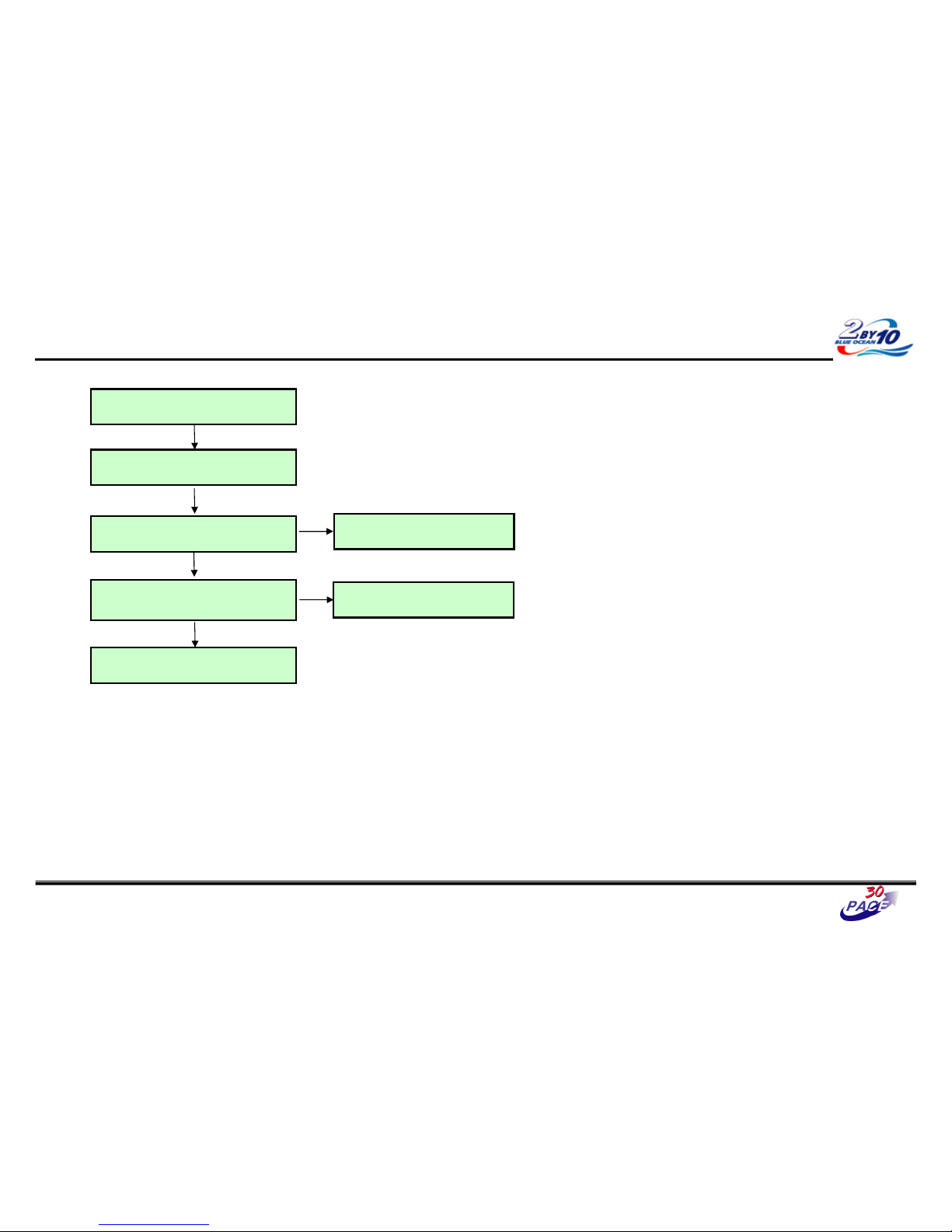
Great Company Great People
AV Video Trouble Shooting
Check input signal format
Is it supported?
Check signal
R105(Rear AV), R106 (Side AV)
Replace Resistor
Y
N
Check AV port of JK100 (Rear)
Check JK101 (Side)
Replace or reseat connector
Y
N
Y
Replace BCM3549XS(IC501)
Check AV Cable / S-Video Cable for damage or
open conductors
Y
21/37
※ Measured signals depend on the input signal.
Page 55
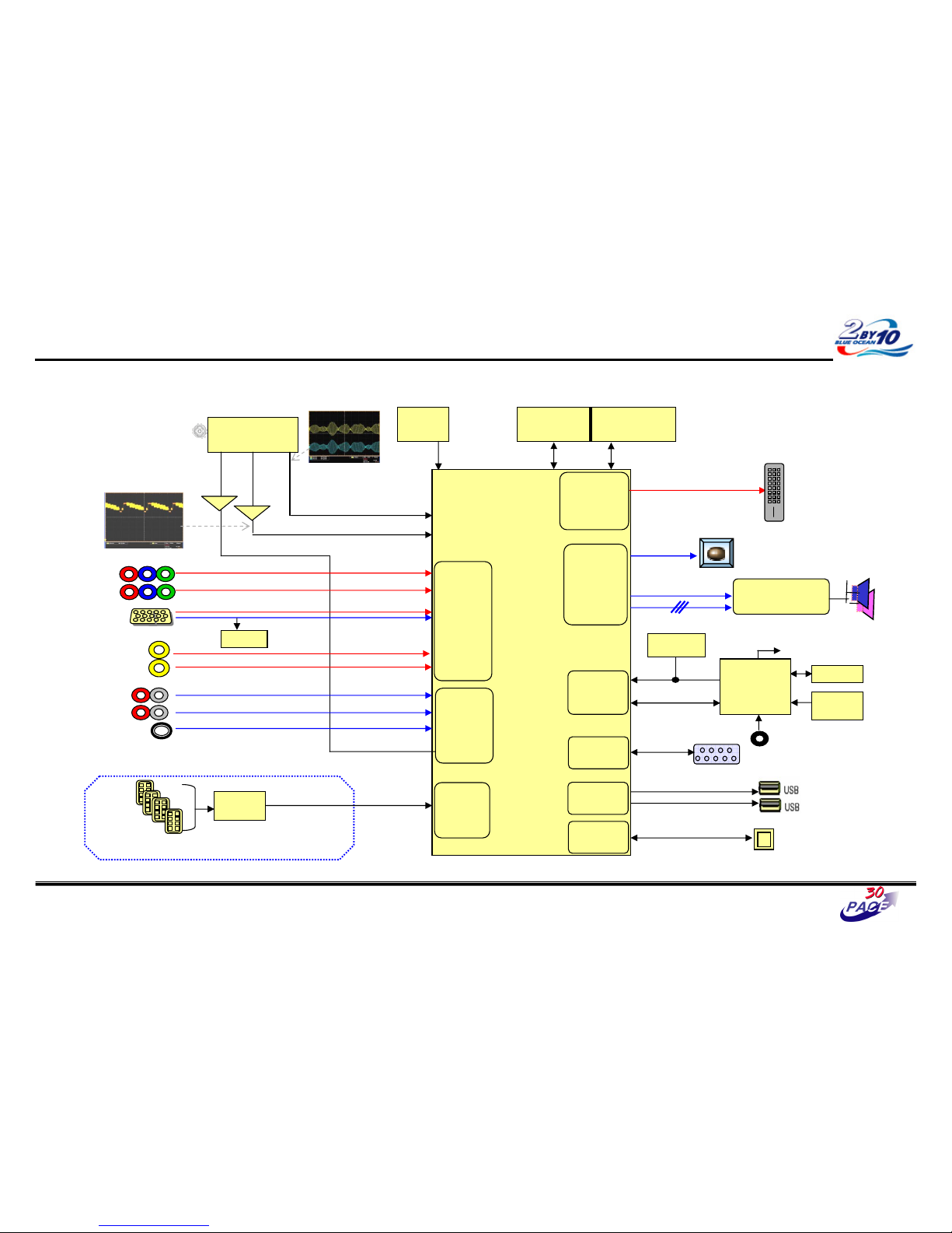
Great Company Great People
HDMI Video Trouble Shooting
22/37
CVBS waveform
IF waveform
TAS5709
(Digital AMP)
Reset
I2S
BCM3549XS
MCLK
HDMI CEC
IR
CVBS
Buffer
SIF
Buffer
RS-232C
I2C
CVBS(ATV)
NTSC/ATSC
TUNER
X-tal
(54MHz)
NAND Flash
(2GB)
DDR2 (512MB)
TDVJ-H001F
KIA7427AF
KIA7427AF
24C16
24C16
Local
Local
KEY
KEY
MAIN IF
DP/DM
DP/DM
NEC
NEC
Micom
Micom
COMP1
COMP2
Y/Cb/Cr
Y/Cb/Cr
R/G/B
RGB-PC
Rear AV
CVBS
Side AV
CVBS
AV1,2 L/R
COMP 1,2 L/R
L/R
L/R
RGB-PC
Audio In
Rear HDMI 1/2/3
Side HDMI 1
SIF
Audio
Front
End
Video
Front
End
TMDS/DDC
HDMI
RX
Digital out
Full HD(1080P)
HD/SD
Video
Encoder
Audio
DSP
SPDIF Out
UART
RX/TX
UART
UART
USB 2.0
RMII
RMII
24C01
DDC
SIF
TDA19997
TDA19997
HDMI SW
LAN
LAN
Page 56
Great Company Great People
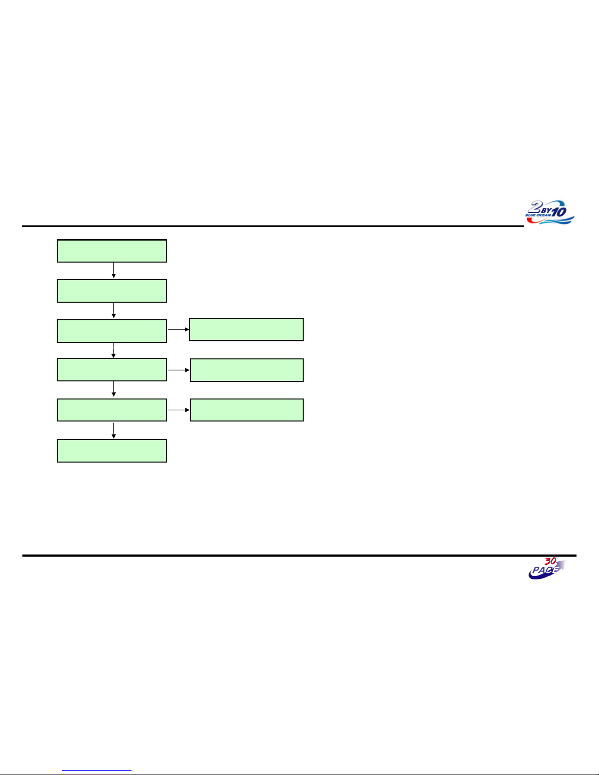
HDMI Video Trouble Shooting
Check input signal format
Is it supported?
Y
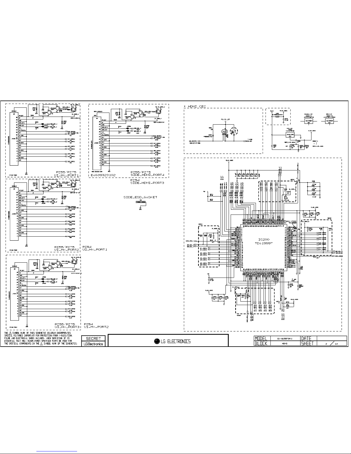
Check JK200~JK203 for proper
connection or damage
Replace connector
Y
N
Y
Check HDMI Cable for damage or open
conductors
Check EDID
SVC REMOTCONTROL
Check HDMI SW(IC200)
Power(L200/1) & I2C Signal(R270/1)
EDID D/L
Y
N
Replace IC200
Y
N
Replace BCM3549XS(IC501)
23/37
Page 57
Great Company Great People
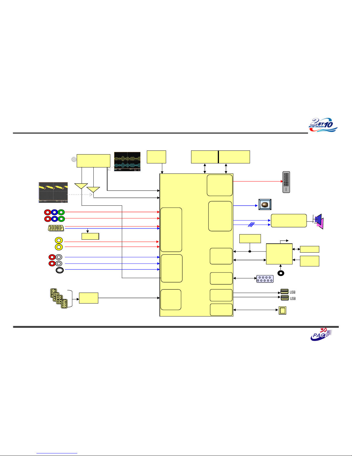
All Source Audio Trouble Shooting
24/37
CVBS waveform
IF waveform
TAS5709
(Digital AMP)
Reset
I2S
BCM3549XS
MCLK
HDMI CEC
IR
CVBS
Buffer
SIF
Buffer
RS-232C
I2C
CVBS(ATV)
NTSC/ATSC
TUNER
X-tal
(54MHz)
NAND Flash
(2GB)
DDR2 (512MB)
TDVJ-H001F
KIA7427AF
KIA7427AF
24C16
24C16
Local
Local
KEY
KEY
MAIN IF
DP/DM
DP/DM
NEC
NEC
Micom
Micom
COMP1
COMP2
Y/Cb/Cr
Y/Cb/Cr
R/G/B
RGB-PC
Rear AV
CVBS
Side AV
CVBS
AV1,2 L/R
COMP 1,2 L/R
L/R
L/R
RGB-PC
Audio In
Rear HDMI 1/2/3
Side HDMI 1
SIF
Audio
Front
End
Video
Front
End
TMDS/DDC
HDMI
RX
Digital out
Full HD(1080P)
HD/SD
Video
Encoder
Audio
DSP
SPDIF Out
UART
RX/TX
UART
UART
USB 2.0
RMII
RMII
24C01
DDC
SIF
TDA19997
TDA19997
HDMI SW
LAN
LAN
Page 58
Great Company Great People
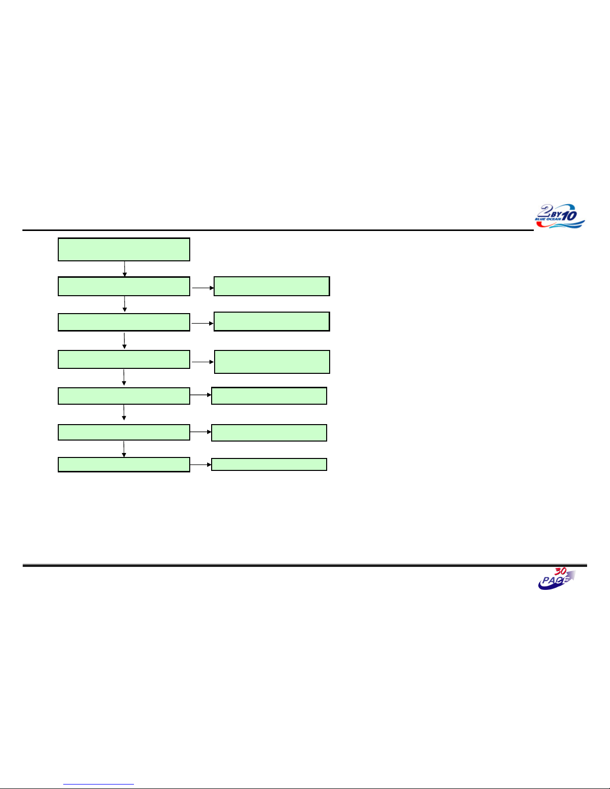
All Source Audio Trouble Shooting
Make sure you can’t hear any audio
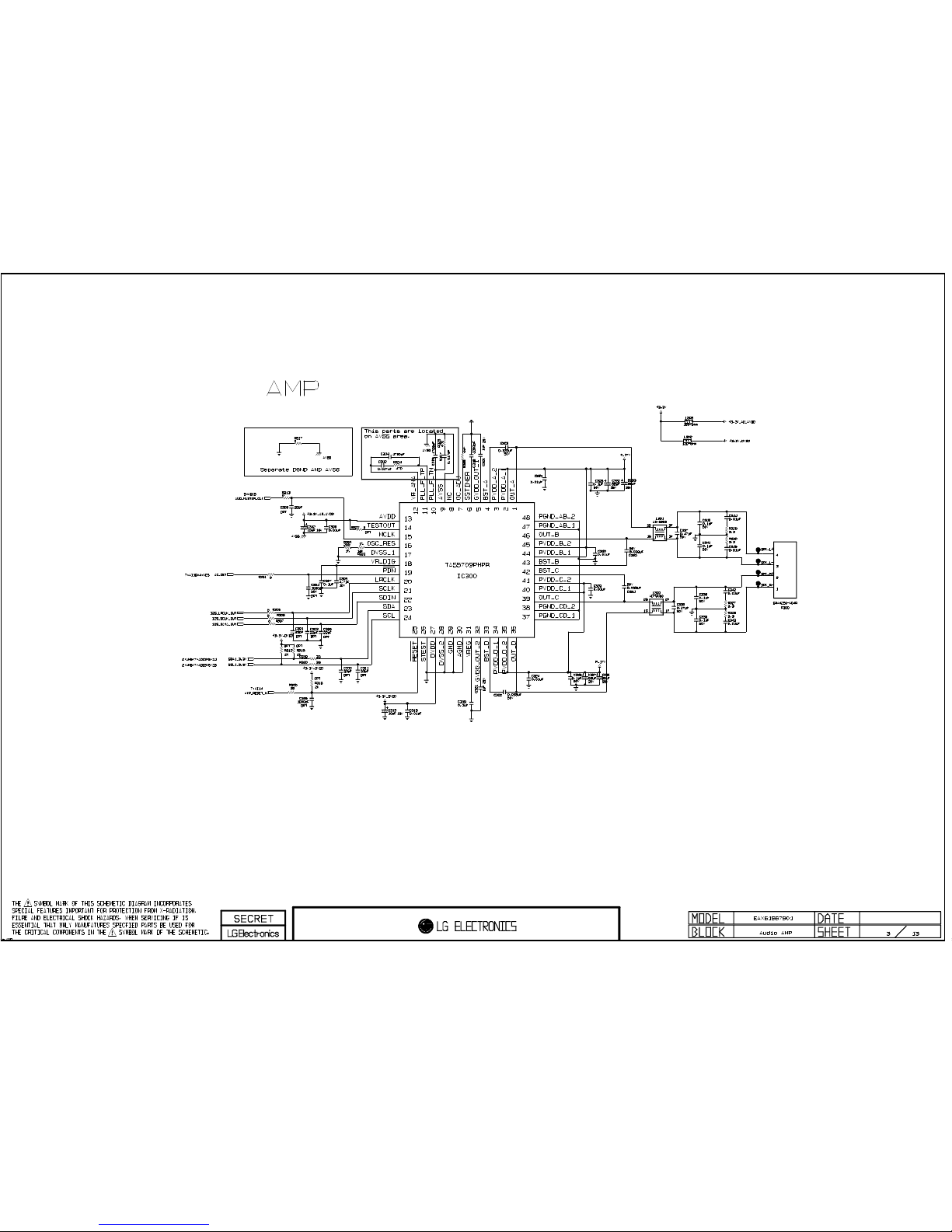
Check Signal (PWM)
L300 L301
Replace L300 L301
Y
N
Check Power
16V(C325), 3.3V(L302)
Check 16V(C325), 3.3V(L302)
Y
N
Check Connector
P300
Check BCM I2S Output
R305~R307
Y
Replace IC501.
N
Check speaker for damage.
Y
Check IC300 Status
/PDN(#19), /Reset(#25) is High?
Replace IC300
N
Replace P300
N
Replace the Speaker
N
Y
Y
25/37
Page 59
Great Company Great People
Digital TV Audio Trouble Shooting
26/37
CVBS waveform
IF waveform
TAS5709
(Digital AMP)
Reset
I2S
BCM3549XS
MCLK
HDMI CEC
IR
CVBS
Buffer
SIF
Buffer
RS-232C
I2C
CVBS(ATV)
NTSC/ATSC
TUNER
X-tal
(54MHz)
NAND Flash
(2GB)
DDR2 (512MB)
TDVJ-H001F
KIA7427AF
KIA7427AF
24C16
24C16
Local
Local
KEY
KEY
MAIN IF
DP/DM
DP/DM
NEC
NEC
Micom
Micom
COMP1
COMP2
Y/Cb/Cr
Y/Cb/Cr
R/G/B
RGB-PC
Rear AV
CVBS
Side AV
CVBS
AV1,2 L/R
COMP 1,2 L/R
L/R
L/R
RGB-PC
Audio In
Rear HDMI 1/2/3
Side HDMI 1
SIF
Audio
Front
End
Video
Front
End
TMDS/DDC
HDMI
RX
Digital out
Full HD(1080P)
HD/SD
Video
Encoder
Audio
DSP
SPDIF Out
UART
RX/TX
UART
UART
USB 2.0
RMII
RMII
24C01
DDC
SIF
TDA19997
TDA19997
HDMI SW
LAN
LAN
Page 60
Great Company Great People
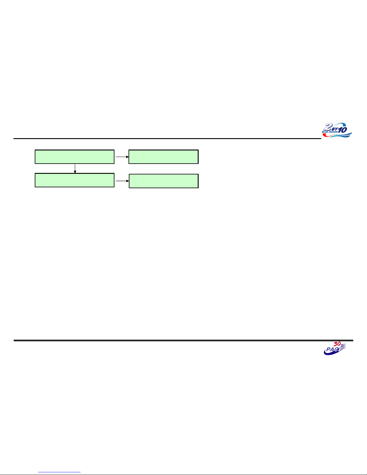
Digital TV Audio Trouble Shooting
Check video output
Follow procedure All source audio trouble
shooting (on page 25)
Y
Follow procedure digital TV video
trouble shooting (on page 13)
N
N
Replace BCM3549XS (IC501)
27/37
Page 61
Great Company Great People
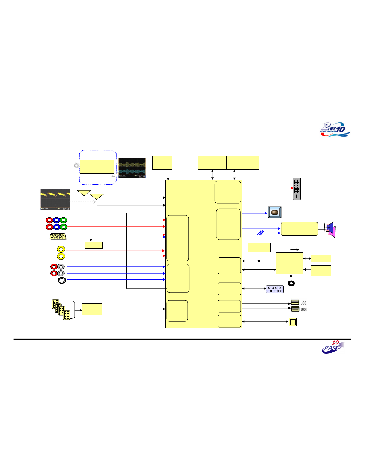
Analog TV Audio Trouble Shooting
28/37
CVBS waveform
IF waveform
TAS5709
(Digital AMP)
Reset
I2S
BCM3549XS
MCLK
HDMI CEC
IR
CVBS
Buffer
SIF
Buffer
RS-232C
I2C
CVBS(ATV)
NTSC/ATSC
TUNER
X-tal
(54MHz)
NAND Flash
(2GB)
DDR2 (512MB)
TDVJ-H001F
KIA7427AF
KIA7427AF
24C16
24C16
Local
Local
KEY
KEY
MAIN IF
DP/DM
DP/DM
NEC
NEC
Micom
Micom
COMP1
COMP2
Y/Cb/Cr
Y/Cb/Cr
R/G/B
RGB-PC
Rear AV
CVBS
Side AV
CVBS
AV1,2 L/R
COMP 1,2 L/R
L/R
L/R
RGB-PC
Audio In
Rear HDMI 1/2/3
Side HDMI 1
SIF
Audio
Front
End
Video
Front
End
TMDS/DDC
HDMI
RX
Digital out
Full HD(1080P)
HD/SD
Video
Encoder
Audio
DSP
SPDIF Out
UART
RX/TX
UART
UART
USB 2.0
RMII
RMII
24C01
DDC
SIF
TDA19997
TDA19997
HDMI SW
LAN
LAN
Page 62
Great Company Great People
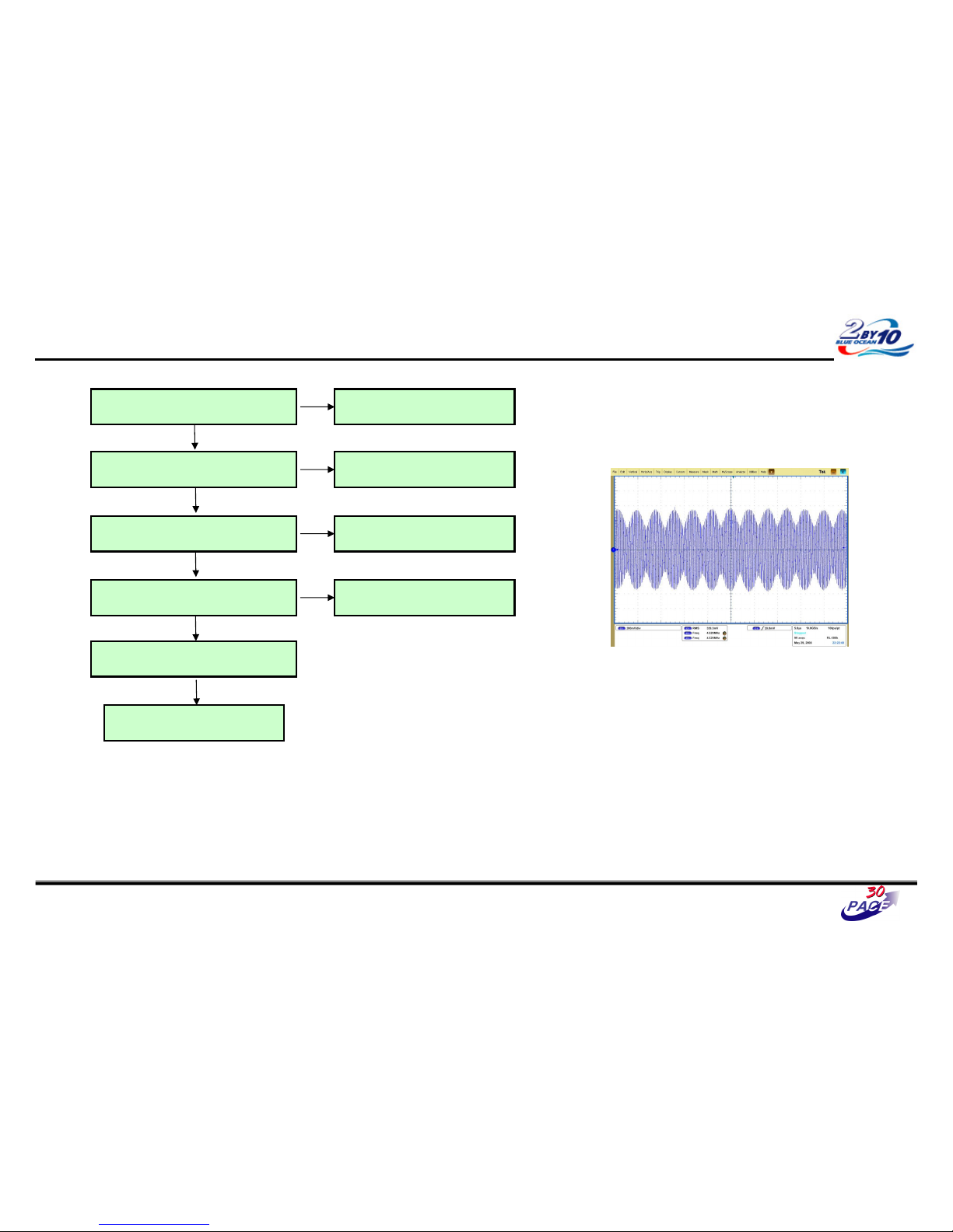
Analog TV Audio Trouble Shooting
Check video output
Follow procedure All source audio trouble
shooting (on page 25)
Y
Follow procedure analog TV video
trouble shooting (on page 15)
N
Replace BCM3549XS (IC501)
Check TU1400 (pin3) for 5V Replace IC404 or IC406
N
Y
Check SIF signal (TU1400 #9) Replace Tuner
N
Y
Check SIF signal (R1439) Check SIF line
N
Y
29/37
< SIF waveform – sample >
- Defend on the input signal.
Y
Page 63
Great Company Great People
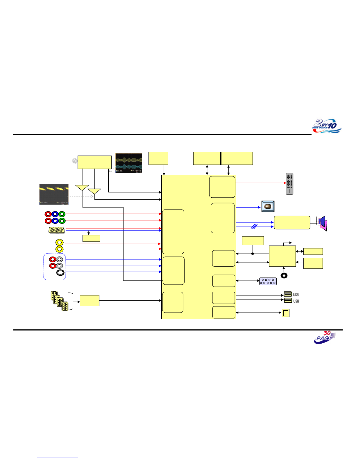
Component / RGB / AV Audio Trouble Shooting
30/37
CVBS waveform
IF waveform
TAS5709
(Digital AMP)
Reset
I2S
BCM3549XS
MCLK
HDMI CEC
IR
CVBS
Buffer
SIF
Buffer
RS-232C
I2C
CVBS(ATV)
NTSC/ATSC
TUNER
X-tal
(54MHz)
NAND Flash
(2GB)
DDR2 (512MB)
TDVJ-H001F
KIA7427AF
KIA7427AF
24C16
24C16
Local
Local
KEY
KEY
MAIN IF
DP/DM
DP/DM
NEC
NEC
Micom
Micom
COMP1
COMP2
Y/Cb/Cr
Y/Cb/Cr
R/G/B
RGB-PC
Rear AV
CVBS
Side AV
CVBS
AV1,2 L/R
COMP 1,2 L/R
L/R
L/R
RGB-PC
Audio In
Rear HDMI 1/2/3
Side HDMI 1
SIF
Audio
Front
End
Video
Front
End
TMDS/DDC
HDMI
RX
Digital out
Full HD(1080P)
HD/SD
Video
Encoder
Audio
DSP
SPDIF Out
UART
RX/TX
UART
UART
USB 2.0
RMII
RMII
24C01
DDC
SIF
TDA19997
TDA19997
HDMI SW
LAN
LAN
Page 64
Great Company Great People
Component / RGB / AV Audio Trouble Shooting
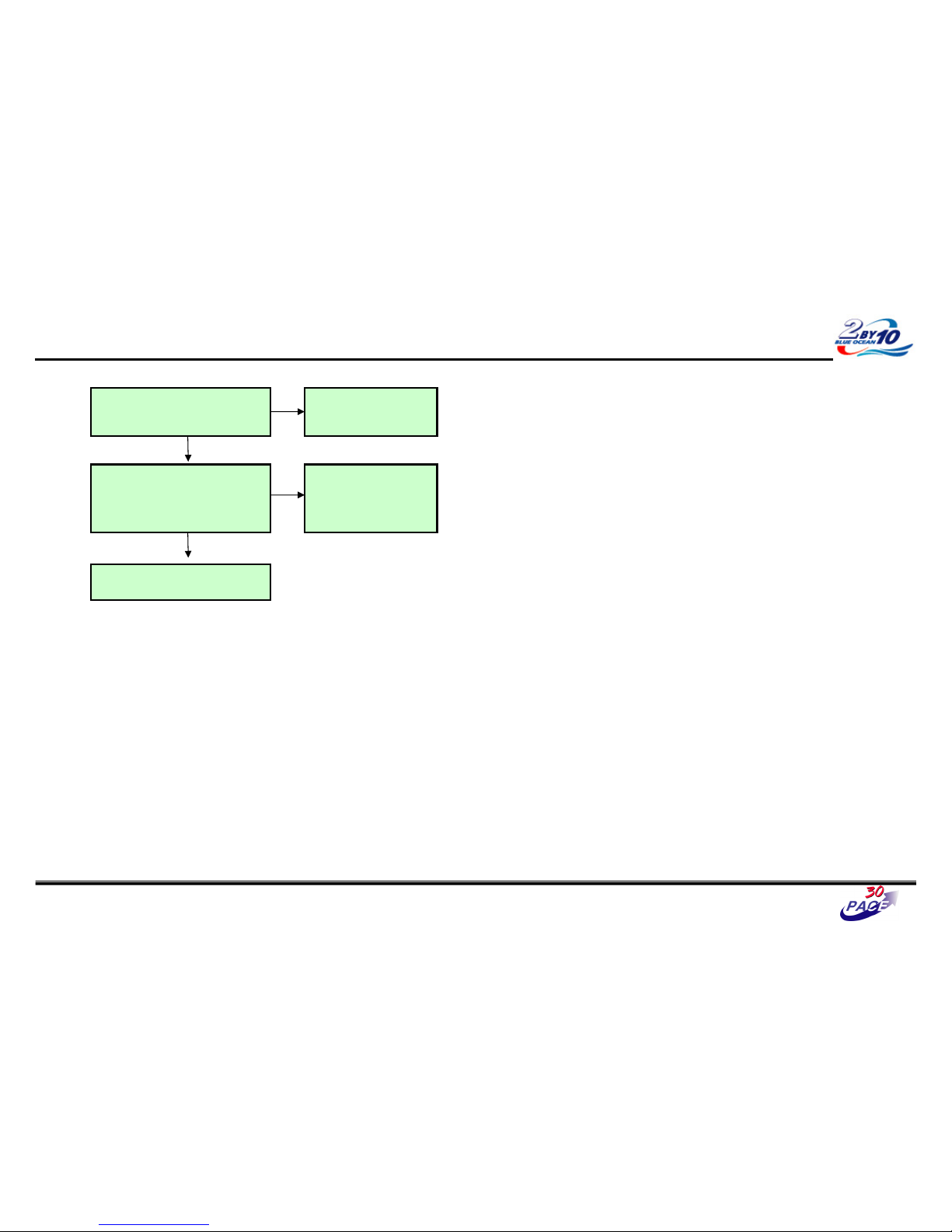
Check Connector and cables
JK100 (Component, AV Rear)
P100 (RGB)
JK101 (AV Side)
Replace connector or cable if
found damaged
N
Y
Check signal
R126 / R127 (Component1)
R117 / R118 (Component2)
R149 / R150 (RGB)
R109 / R110 (AV Rear)
R111 / R112 (AV Side)
Replace the Resistor
N
Y
31/37
Follow procedure All source audio
trouble shooting (on page 25)
Page 65
Great Company Great People
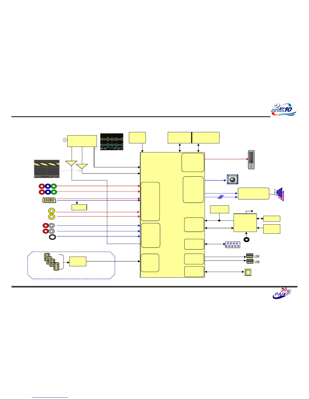
HDMI Audio Trouble Shooting
32/37
CVBS waveform
IF waveform
TAS5709
(Digital AMP)
Reset
I2S
BCM3549XS
MCLK
HDMI CEC
IR
CVBS
Buffer
SIF
Buffer
RS-232C
I2C
CVBS(ATV)
NTSC/ATSC
TUNER
X-tal
(54MHz)
NAND Flash
(2GB)
DDR2 (512MB)
TDVJ-H001F
KIA7427AF
KIA7427AF
24C16
24C16
Local
Local
KEY
KEY
MAIN IF
DP/DM
DP/DM
NEC
NEC
Micom
Micom
COMP1
COMP2
Y/Cb/Cr
Y/Cb/Cr
R/G/B
RGB-PC
Rear AV
CVBS
Side AV
CVBS
AV1,2 L/R
COMP 1,2 L/R
L/R
L/R
RGB-PC
Audio In
Rear HDMI 1/2/3
Side HDMI 1
SIF
Audio
Front
End
Video
Front
End
TMDS/DDC
HDMI
RX
Digital out
Full HD(1080P)
HD/SD
Video
Encoder
Audio
DSP
SPDIF Out
UART
RX/TX
UART
UART
USB 2.0
RMII
RMII
24C01
DDC
SIF
TDA19997
TDA19997
HDMI SW
LAN
LAN
Page 66
Great Company Great People
HDMI Audio Trouble Shooting
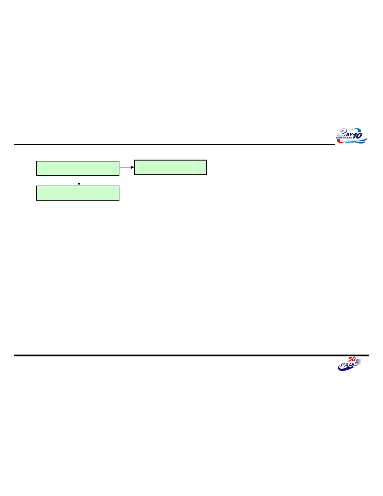
Follow procedure All source audio trouble
shooting (on page 25)
Check EDID
Re-download EDID data.
Y
N
33/37
Page 67
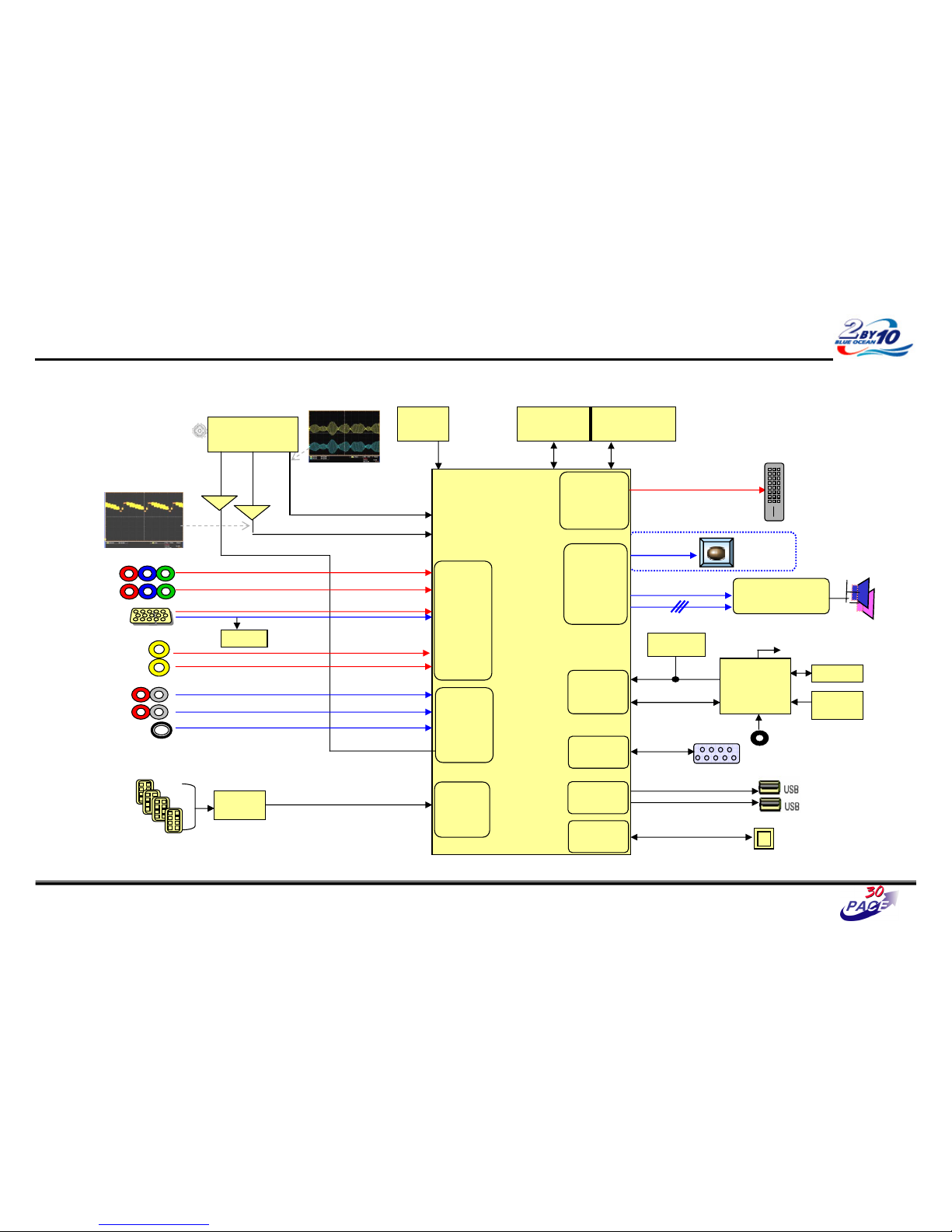
Great Company Great People
OPTIC Audio Out Trouble Shooting
34/37
CVBS waveform
IF waveform
TAS5709
(Digital AMP)
Reset
I2S
BCM3549XS
MCLK
HDMI CEC
IR
CVBS
Buffer
SIF
Buffer
RS-232C
I2C
CVBS(ATV)
NTSC/ATSC
TUNER
X-tal
(54MHz)
NAND Flash
(2GB)
DDR2 (512MB)
TDVJ-H001F
KIA7427AF
KIA7427AF
24C16
24C16
Local
Local
KEY
KEY
MAIN IF
DP/DM
DP/DM
NEC
NEC
Micom
Micom
COMP1
COMP2
Y/Cb/Cr
Y/Cb/Cr
R/G/B
RGB-PC
Rear AV
CVBS
Side AV
CVBS
AV1,2 L/R
COMP 1,2 L/R
L/R
L/R
RGB-PC
Audio In
Rear HDMI 1/2/3
Side HDMI 1
SIF
Audio
Front
End
Video
Front
End
TMDS/DDC
HDMI
RX
Digital out
Full HD(1080P)
HD/SD
Video
Encoder
Audio
DSP
SPDIF Out
UART
RX/TX
UART
UART
USB 2.0
RMII
RMII
24C01
DDC
SIF
TDA19997
TDA19997
HDMI SW
LAN
LAN
Page 68
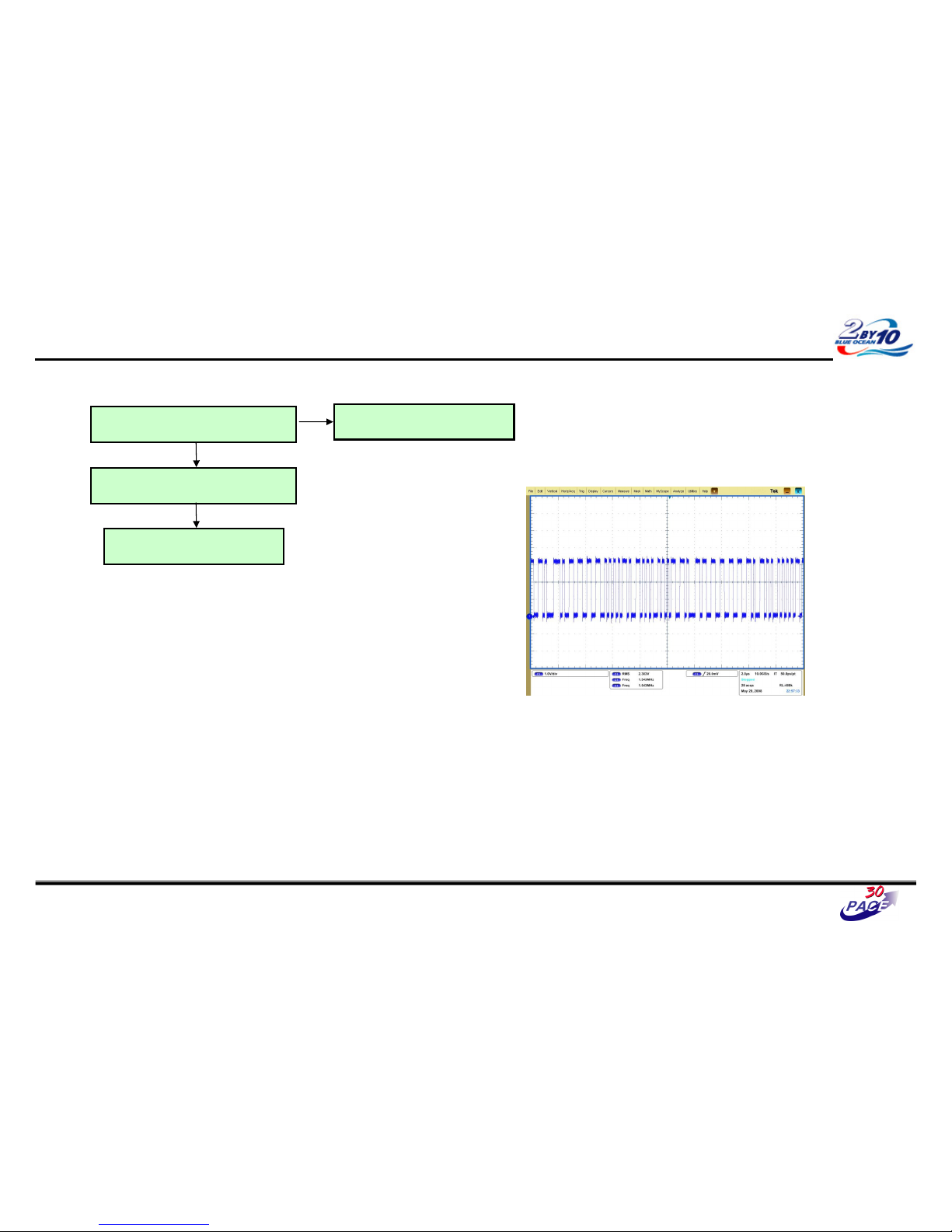
Great Company Great People
Check Signal (JK104 #3)
Check SPDIF signal (R140)
Replace BCM3549XS (IC501)
Y
N
OPTIC Audio Out Trouble Shooting
35/37
Y
Replace JK104
< SPDIF waveform – sample >
- Defend on the input signal.
Page 69
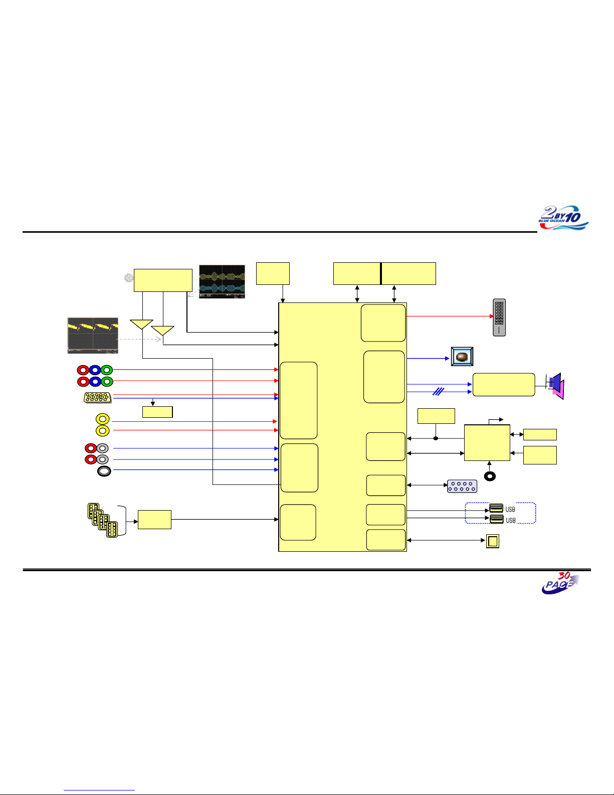
Great Company Great People
USB Trouble Shooting
36/37
CVBS waveform
IF waveform
TAS5709
(Digital AMP)
Reset
I2S
BCM3549XS
MCLK
HDMI CEC
IR
CVBS
Buffer
SIF
Buffer
RS-232C
I2C
CVBS(ATV)
NTSC/ATSC
TUNER
X-tal
(54MHz)
NAND Flash
(2GB)
DDR2 (512MB)
TDVJ-H001F
KIA7427AF
KIA7427AF
24C16
24C16
Local
Local
KEY
KEY
MAIN IF
DP/DM
DP/DM
NEC
NEC
Micom
Micom
COMP1
COMP2
Y/Cb/Cr
Y/Cb/Cr
R/G/B
RGB-PC
Rear AV
CVBS
Side AV
CVBS
AV1,2 L/R
COMP 1,2 L/R
L/R
L/R
RGB-PC
Audio In
Rear HDMI 1/2/3
Side HDMI 1
SIF
Audio
Front
End
Video
Front
End
TMDS/DDC
HDMI
RX
Digital out
Full HD(1080P)
HD/SD
Video
Encoder
Audio
DSP
SPDIF Out
UART
RX/TX
UART
UART
USB 2.0
RMII
RMII
24C01
DDC
SIF
TDA19997
TDA19997
HDMI SW
LAN
LAN
Page 70
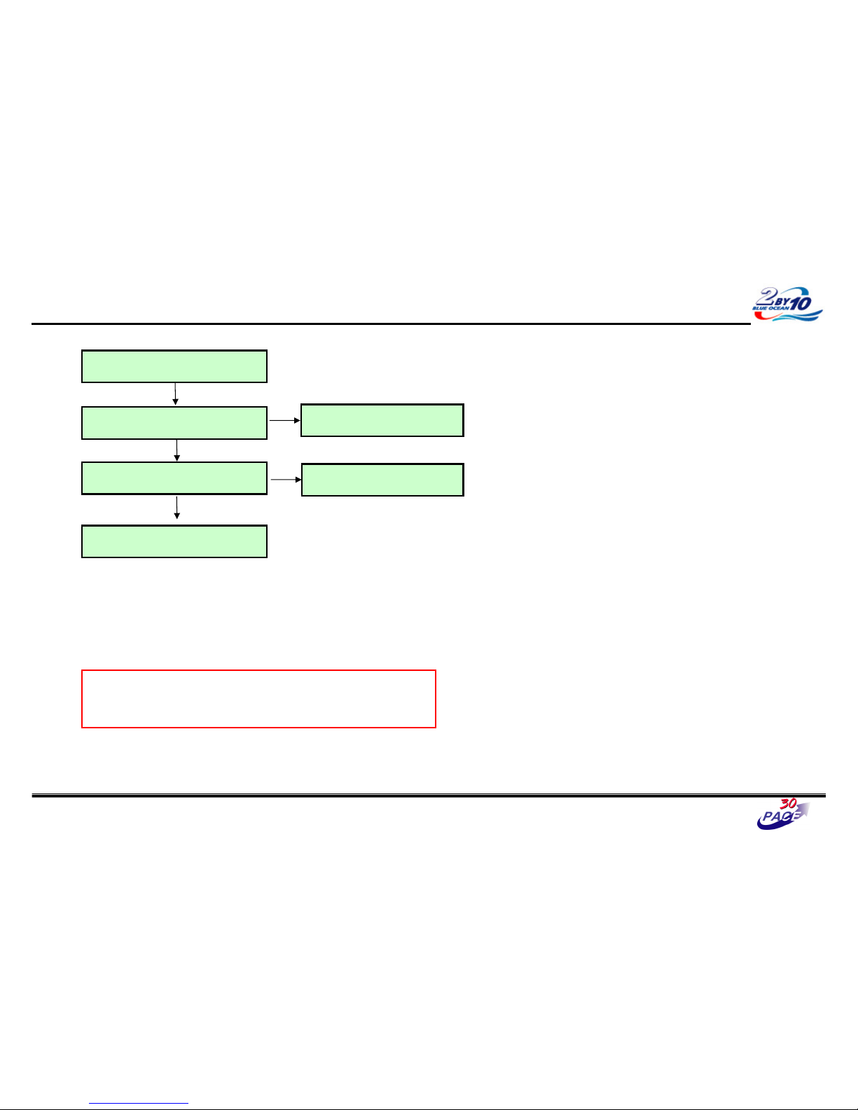
Great Company Great People
USB Trouble Shooting
Check USB 2.0 Cable for damage or open
conductors
Check IC1101/2 voltage level 5V
Y
N
Replace IC1101/2
Check P1101/2
Replace P601
Y
N
Replace BCM3549XS (IC501)
Y
• Exception
- USB power could be disabled by inrushing current
- In this case, remove the device and try to reboot the TV (AC power off/on)
37/37
 Loading...