

LG 60PG30 Owner’s Manual

0
(%
PLASMA TV
OWNER'S MANUAL
42PG10 50PG10
42PG20 50PG20
42PG20C 50PG20C
50PG30 60PG30
50PG30C 60PG30C
ENERGY STAR is a set of power-saving
guidelines issued by the U.S.
Environmental Protection Agency(EPA).
As an ENERGYSTAR
Partner LGEU. S.A.,Inc.
hasdetermined that this
product meets the
ENERGYSTAR guidelines
for energy efficiency.
Please read this manual carefully before operating
your set.
Retain it for future reference.
Record model number and serial number of the set.
See the label attached on the back cover and quote
this information to yo
when you requi
P/NO : SAC30708031 (0808-REV04)
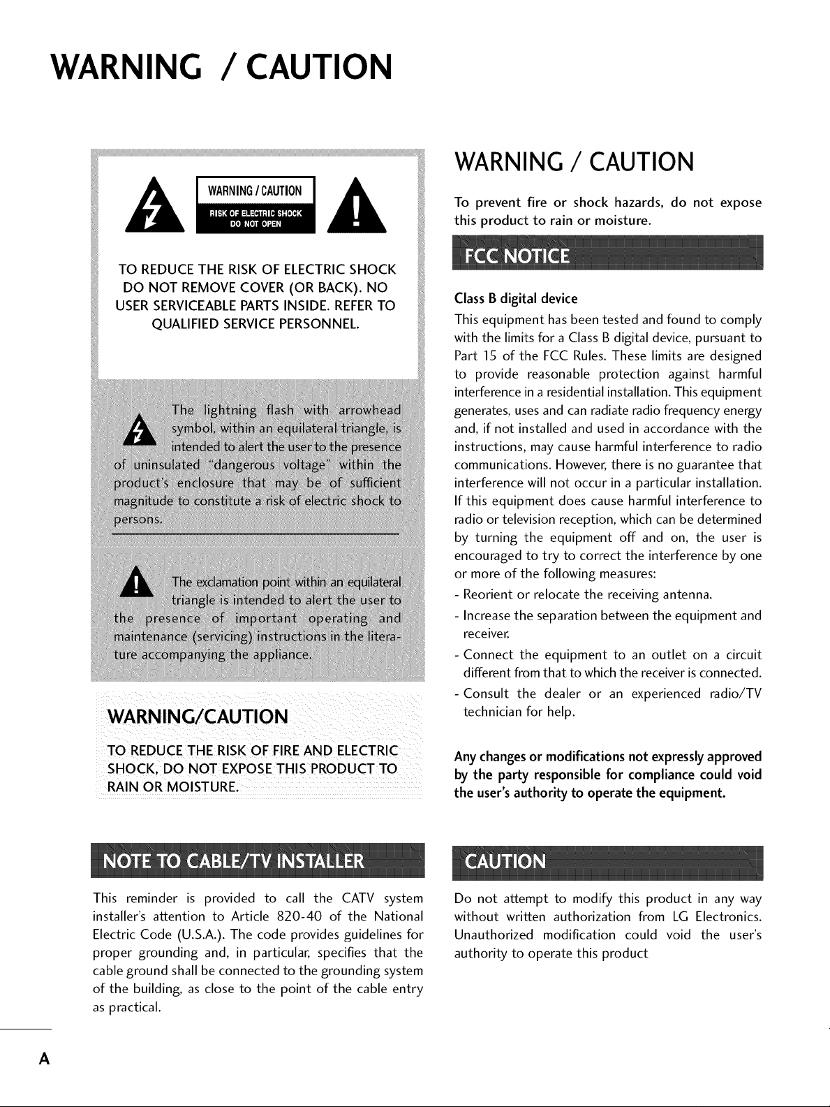
WARNING / CAUTION
WARNING / CAUTION
WARNING/CAUTION
TO REDUCE THE RISK OF ELECTRICSHOCK
DO NOT REMOVE COVER (OR BACK). NO
USER SERVICEABLEPARTSINSIDE. REFERTO
QUALIFIED SERVICEPERSONNEL.
To prevent fire or shock hazards, do not expose
this product to rain or moisture.
Class B digital device
This equipment has been tested and found to comply
with the limits for a Class B digital device, pursuant to
Part 15 of the FCC Rules. These limits are designed
to provide reasonable protection against harmful
interference in a residential installation. This equipment
generates, uses and can radiate radio frequency energy
and, if not installed and used in accordance with the
instructions, may cause harmful interference to radio
communications. However, there is no guarantee that
interference will not occur in a particular installation.
If this equipment does cause harmful interference to
radio or television reception, which can be determined
by turning the equipment off and on, the user is
encouraged to try to correct the interference by one
or more of the following measures:
- Reorient or relocate the receiving antenna.
- Increase the separation between the equipment and
receiver.
- Connect the equipment to an outlet on a circuit
different from that to which the receiver is connected.
-Consult the dealer or an experienced radio/TV
technician for help.
TO REDUCETHE RISK OF FIREAND ELECTRIC
RAIN OR MOISTURE,
This reminder is provided to call the CATV system
installer's attention to Article 820-40 of the National
Electric Code (U.S.A.). The code provides guidelines for
proper grounding and, in particular, specifies that the
cable ground shall be connected to the grounding system
of the building, as close to the point of the cable entry
as practical.
Any changes or modifications not expressly approved
by the party responsible for compliance could void
the user's authority to operate the equipment.
Do not attempt to modify this product in any way
without written authorization from LG Electronics.
Unauthorized modification could void the user's
authority to operate this product
A
SAFETYINSTRUCTIONS
IMPORTANT SAFETYINSTRUCTIONS
Read these instructions.
Keep these instructions.
Heed all warnings.
Follow all instructions.
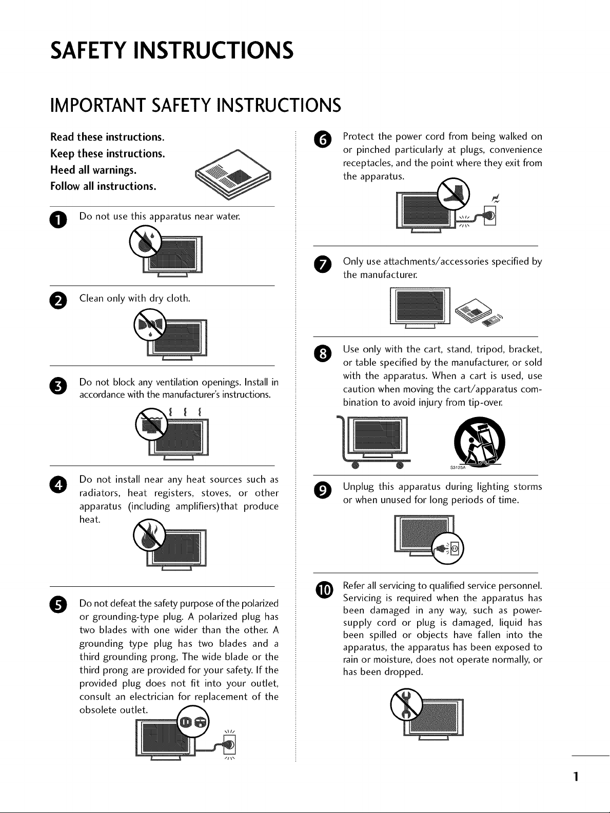
O Do not use this apparatus nearwater.
Clean only with dry cloth.
Do not block any ventilation openings. Install in
accordance with the manufacturer's instructions.
Protect the power cord from being walked on
0
or pinched particularly at plugs, convenience
receptacles, and the point where they exit from
the apparatus.
Only use attachments/accessories specified by
the manufacturer.
Use only with the cart, stand, tripod, bracket,
0
or table specified by the manufacturer, or sold
with the apparatus. When a cart is used, use
caution when moving the cart/apparatus com-
bination to avoid injury from tip-over.
Do not install near any heat sources such as
O
radiators, heat registers, stoves, or other
apparatus (including amplifiers)that produce
heat.
Do not defeat the safety purpose of the polarized
0
or grounding-type plug. A polarized plug has
two blades with one wider than the other. A
grounding type plug has two blades and a
third grounding prong, The wide blade or the
third prong are provided for your safety. If the
provided plug does not fit into your outlet,
consult an electrician for replacement of the
obsolete outlet.
@
S3125A
Unplug this apparatus during lighting storms
or when unused for long periods of time.
Refer all servicing to qualified service personnel.
@
Servicing is required when the apparatus has
been damaged in any way, such as power-
supply cord or plug is damaged, liquid has
been spilled or objects have fallen into the
apparatus, the apparatus has been exposed to
rain or moisture, does not operate normally, or
has been dropped.
SAFETYINSTRUCTIONS
Never touch this apparatus or antenna during
a thunder or lighting storm.
When mounting a TV on the wall, make sure
0
not to install the TV by the hanging power and
signal cables on the back of the TV.
Do not allow an impact shock or any objects to
0
fall into the product, and do not drop onto the
screen with something.
CAUTION concerning the Power Cord:
0
It is recommend that appliances be placed
upon a dedicated circuit; that is, a single
outlet circuit which powers only that appliance
and has no additional outlets or branch
circuits. Check the specification page of this
owner's manual to be certain.
Do not connect too many appliances to the
same AC power outlet as this could result in
fire or electric shock.
Do not overload wall outlets. Overloaded wall
outlets, loose or damaged wall outlets, extension
cords, frayed power cords, or damaged or
cracked wire insulation are dangerous. Any of
these conditions could result in electric shock
or fire. Periodically examine the cord of your
appliance, and if its appearance indicates damage
or deterioration, unplug it, discontinue use of
the appliance, and have the cord replaced with
an exact replacement part by an authorized
servicer. Protect the power cord from physical
or mechanical abuse, such as being twisted,
kinked, pinched, closed in a door, or walked
upon. Pay particular attention to plugs, wall
outlets, and the point where the cord exits the
appliance.
Do not make the TV with the power cord
plugged in. Do not use a damaged or loose
power cord. Be sure do grasp the plug when
unplugging the power cord. Do not pull on the
power cord to unplug the TV.
WARNING - To reduce the risk of fire or electrical
O
shock, do not expose this product to rain,
moisture or other liquids. Do not touch the TV
with wet hands. Do not install this product
near flammable objects such as gasoline or
candles or expose the TV to direct air
conditioning.
Do not expose to dripping or splashing and do
not place objects filled with liquids, such as
vases, cups, etc. on or over the apparatus (e.g.
on shelves above the unit).
GROUNDING
O
Ensure that you connect the earth ground wire
to prevent possible electric shock (i.e. a TV
with a three-prong grounded AC plug must be
connected to a three-prong grounded AC out-
let). If grounding methods are not possible,
have a qualified electrician install a separate
circuit breaker.
Do not try to ground the unit by connecting it
to telephone wires, lightening rods, or gas
pipes.
DISCONNECTING DEVICE FROM MAINS
O
Mains plug is the disconnecting device. The
plug must remain readily operable.
Power
Supply
Keep the product away from direct sunlight.
2
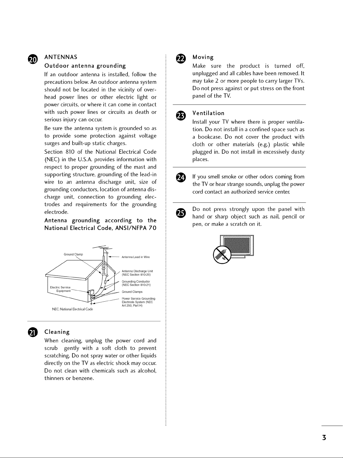
ANTENNAS
@
Outdoor antenna grounding
If an outdoor antenna is installed, follow the
precautions below. An outdoor antenna system
should not be located in the vicinity of over-
head power lines or other electric light or
power circuits, or where it can come in contact
with such power lines or circuits as death or
serious injury can occur.
Be sure the antenna system is grounded so as
to provide some protection against voltage
surges and built-up static charges.
Section 810 of the National Electrical Code
(NEC) in the U.S.A. provides information with
respect to proper grounding of the mast and
supporting structure, grounding of the lead-in
wire to an antenna discharge unit, size of
grounding conductors, location of antenna dis-
charge unit, connection to grounding elec-
trodes and requirements for the grounding
electrode.
Antenna grounding according to the
National Electrical Code, ANSl/NFPA 70
Moving
Make sure the product is turned off,
unplugged and all cables have been removed. It
may take 2 or more people to carry larger TVs.
Do not press against or put stress on the front
panel of the TV.
Ventilation
Install your TV where there is proper ventila-
tion. Do not install in a confined space such as
a bookcase. Do not cover the product with
cloth or other materials (e.g.) plastic while
plugged in. Do not install in excessively dusty
places.
you
If smell smoke or other odors coming from
the TV or hearstrange sounds,unplug the power
cord contact an authorized servicecenter.
Do not press strongly upon the panel with
hand or sharp object such as nail, pencil or
pen, or make a scratch on it.
Ground Clamp
NEC: National Electrical Code
Cleaning
O
When cleaning, unplug the power cord and
scrub gently with a soft cloth to prevent
scratching. Do not spray water or other liquids
directly on the TV as electric shock may occur.
Do not clean with chemicals such as alcohol,
thinners or benzene.
Antenna Lead in Wire
Antenna Discharge Unit
(NEC Section 810-20)
Grounding Conductor
(NEC Section 810-21)
Ground Clamps
Power Service Grounding
Electrode System (NEC
Art 250, Part H)
3
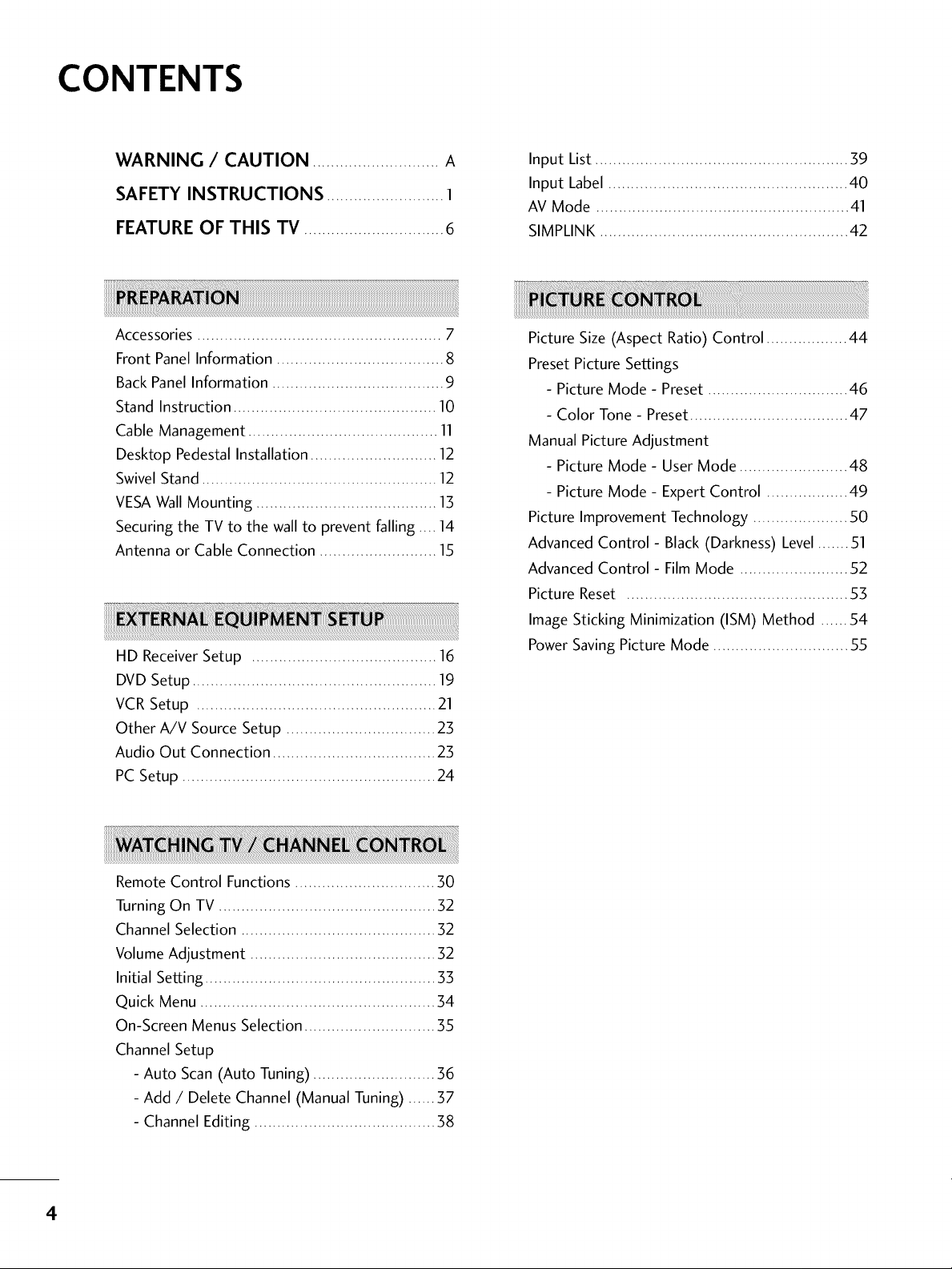
CONTENTS
WARNING / CAUTION ............................ A
SAFETY INSTRUCTIONS .......................... 1
FEATURE OF THIS TV ............................... 6
Accessories ...................................................... 7
Front Panel Information ..................................... 8
Back Panel Information ...................................... 9
Stand Instruction ............................................. 10
Cable Management .......................................... 11
Desktop Pedestal Installation ............................ 12
Swivel Stand .................................................... 12
VESAWall Mounting ........................................ 13
Securing the TV to the wall to prevent falling .... 14
Antenna or Cable Connection .......................... 15
HD Receiver Setup ......................................... 16
DVD Setup ...................................................... 19
VCR Setup ..................................................... 21
Other A/V Source Setup ................................. 23
Audio Out Connection .................................... 23
PC Setup ........................................................ 24
Input List ........................................................ 39
Input Label ..................................................... 40
AV Mode ........................................................ 41
SIMPLINK ....................................................... 42
Picture Size (Aspect Ratio) Control .................. 44
Preset Picture Settings
- Picture Mode - Preset ............................... 46
- Color Tone - Preset................................... 47
Manual Picture Adjustment
- Picture Mode - User Mode ........................ 48
- Picture Mode - Expert Control .................. 49
Picture Improvement Technology ..................... 50
Advanced Control- Black (Darkness) Level....... 51
Advanced Control- Film Mode ........................ 52
Picture Reset ................................................. 53
Image Sticking Minimization (ISM) Method ...... 54
Power Saving Picture Mode .............................. 55
Remote Control Functions ............................... 30
Turning On TV ................................................ 32
Channel Selection ........................................... 32
Volume Adjustment ......................................... 32
Initial Setting ................................................... 33
Quick Menu .................................................... 34
On-Screen Menus Selection ............................. 35
Channel Setup
- Auto Scan (Auto Tuning) ........................... 36
- Add / Delete Channel (Manual Tuning) ...... 37
- Channel Editing ........................................ 38
4
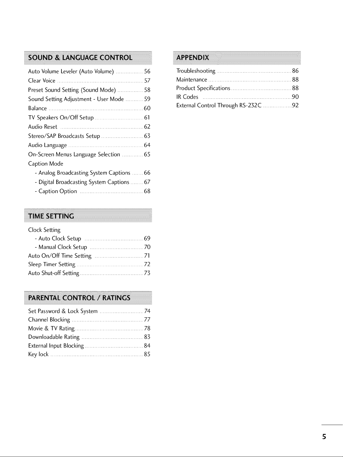
Auto Volume Leveler (Auto Volume) ................. _%
Clear Voice ..................................................... 57
Preset Sound Setting (Sound Mode) ................ 58
Sound Setting Adjustment - User Mode ........... 59
Balance .......................................................... 60
TV SpeakersOn/Off Setup .............................. 61
Audio Reset ................................................... 62
Stereo/SAP Broadcasts Setup .......................... 63
Audio Language .............................................. 64
On-Screen Menus Language Selection ............. 65
Caption Mode
- Analog Broadcasting System Captions ....... 66
- Digital Broadcasting System Captions ........ 67
- Caption Option ....................................... 68
Clock Setting
- Auto Clock Setup .................................... 69
- Manual Clock Setup ................................. 70
Auto On/Off Time Setting .............................. 71
Sleep Timer Setting ......................................... 72
Auto Shut-off Setting ....................................... 73
Troubleshooting .............................................. 86
Maintenance ................................................... 88
Product Specifications ..................................... 88
IR Codes ....................................................... 90
External Control Through RS-232C .................. 92
Set Password& LockSystem ........................... 74
Channel Blocking ............................................ 77
Movie & TV Rating .......................................... 78
Downloadable Rating ...................................... 83
External Input Blocking .................................... 84
Key lock ......................................................... 85
S
FEATURE OF THIS TV
SRS(O) _
D , _ I T A L
_ is a trademarkof SRSLabs,Inc.
TruSurround XT technology is incorporated under
licensefrom SRSLabs,Inc.
ITI DOLBY
DIGITAL I
Manufactured under license from Dolby Laboratories.
"Dolby "and the double-D symbol are trademarks of
Dolby Laboratories.
6
PREPARATION
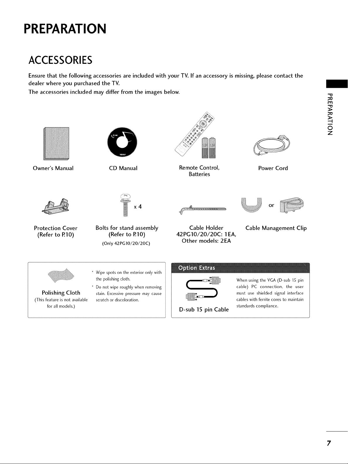
ACCESSORIES
Ensure that the following accessories are included with your TV. If an accessory is missing, please contact the
dealer where you purchased the TV.
The accessories included may differ from the images below.
"O
_o
rT1
_o
©
z
Owner's Manual CD Manual Remote Control,
Batteries
x4
Protection Cover
(Refer to RIO)
Polishing Cloth
(This feature is not available
for all models.)
Bolts for stand assembly
(Refer to P.IO)
(Only 42PG10/20/20C)
* Wipe spots on the exterior only with
the polishing cloth.
* Do not wipe roughly when removing
stain. Excessive pressure may cause
scratch or discoloration.
Cable Holder
42PG10/20/20C: 1 EA,
Other models: 2EA
D-sub 15 pin Cable
Power Cord
or
Cable Management Clip
When using the VGA (D-sub 15 pin
cable) PC connection, the user
must use shielded signal interface
cables with ferrite cores to maintain
standards compliance.
7
PREPARATION
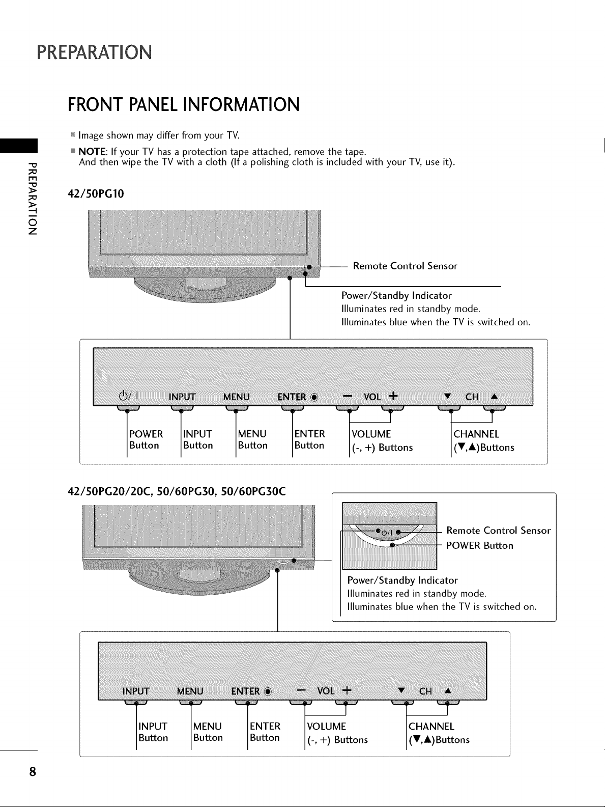
FRONTPANELINFORMATION
_ Image shown may differ from your TV.
""_NOTE: If your TV has a protection tape attached, remove the tape.
-O
_a
And then wipe the TV with a cloth (If a polishing cloth is included with your TV, use it).
_a
i
O
z
42/50PGI0
POWER INPUT MENU ENTER
Button Button Button Button
-- Remote Control Sensor
Power/Sta nd by Indicator
Illuminates red in standby mode.
Illuminates blue when the TV is switched on.
VOLUME CHANNEL
(-, +) Buttons (V,&)Buttons
42/50PG20/20C, SO/60PG30, SO/60PG30C
Remote Control Sensor
POWER Button
Power/Standby Indicator
Illuminates red in standby mode.
Illuminates blue when the TV is switched on.
_ _ii_¸ _i_i_,¸ _iiiii_,
TINPUT
Button
MENU
Button
ENTER
Button
I(-, +) Buttons
CHANNEL
(T,&)Buttons
8
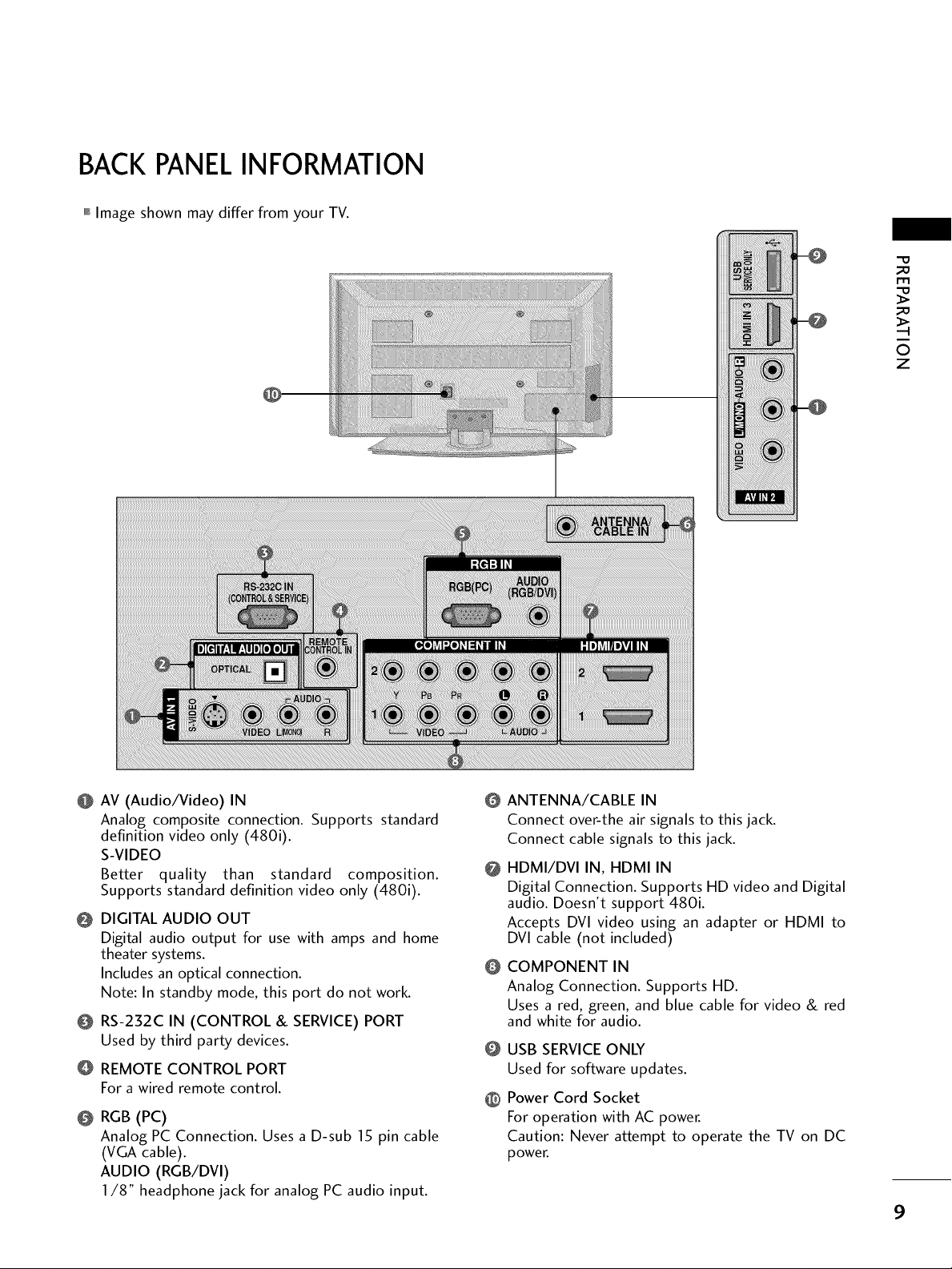
BACKPANELINFORMATION
,,,IImage shown may differ from your TV.
m
0
z
@ AV (Audio/Video) IN
Analog composite connection. Supports standard
definition video only (480i).
S-VIDEO
Better quality than standard composition.
Supports standard definition video only (480i).
@ DIGITAL AUDIO OUT
Digital audio output for use with amps and home
theater systems.
Includes an optical connection.
Note: In standby mode, this port do not work.
O RS-232C IN (CONTROL & SERVICE) PORT
Used by third party devices.
REMOTE CONTROL PORT
For a wired remote control.
@ RGB (PC)
Analog PC Connection. Uses a D-sub 15 pin cable
(VGA cable).
AUDIO (RGB/DVl)
1/8" headphone jack for analog PC audio input.
ANTENNA/CABLE IN
@
Connect over-the air signals to this jack.
Connect cable signals to this jack.
HDMI/DVI IN, HDMI IN
@
Digital Connection. Supports HD video and Digital
audio. Doesn't support 480i.
Accepts DVI video using an adapter or HDMI to
DVI cable (not included)
COMPONENT IN
@
Analog Connection. Supports HD.
Uses a red, green, and blue cable for video & red
and white for audio.
@ USB SERVICE ONLY
Used for software updates.
@ Power Cord Socket
For operation with AC power.
Caution: Never attempt to operate the TV on DC
power.
9
PREPARATION
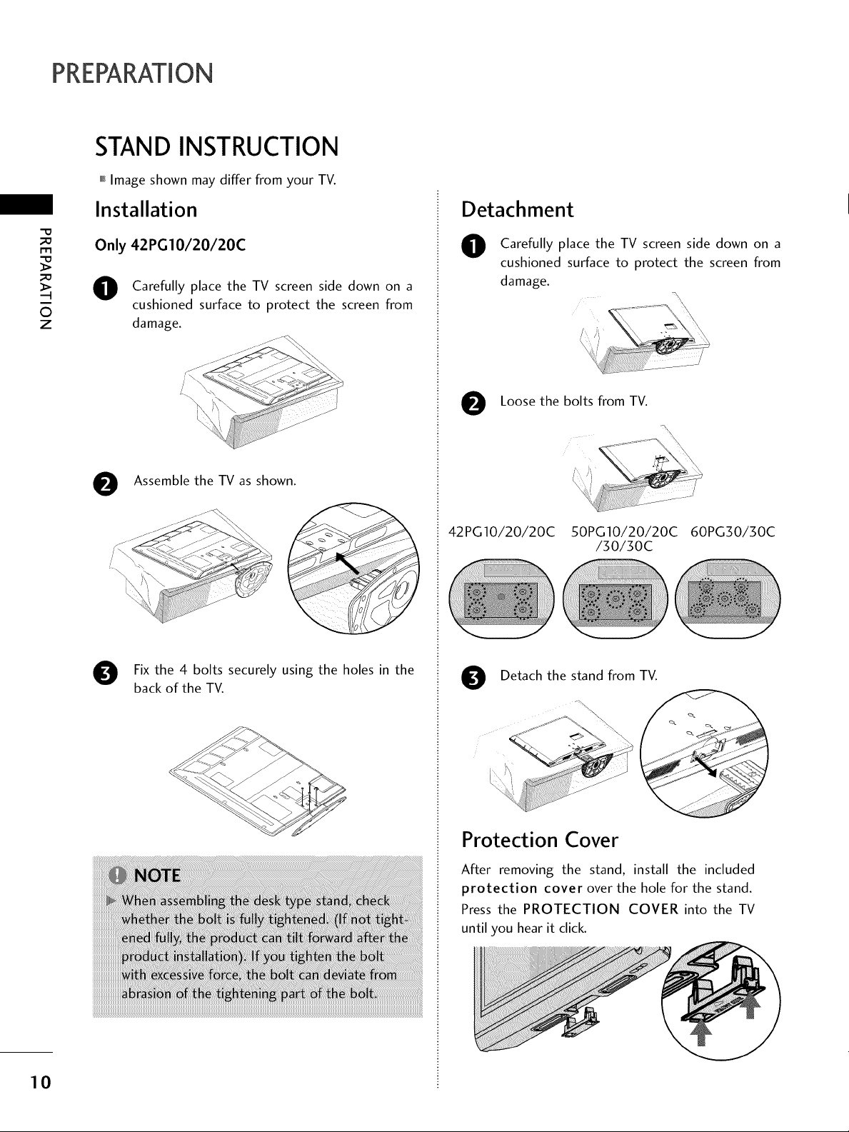
STAND INSTRUCTION
,,,IImage shown may differ from your TV.
Installation
"0
_o
r_
_o
i
©
z
Only 42 PG10/20/20C
Carefully place the TV screen side down on a
0
cushioned surface to protect the screen from
damage.
/i
e Assemble the TV as shown.
ii'f _ J_/J_/J°JJJJJJJ_
i
Detachment
Carefully place the TV screen side down on a
0
cushioned surface to protect the screen from
damage.
e Loose the bolts from TV.
42PG10/20/20C 50PG10/20/20C 60PG30/30C
/30/30C
\
10
Fix the 4 bolts securely using the holes in the
back of the TV.
Detach the stand from TV.
Protection Cover
After removing the stand, install the included
protection cover over the hole for the stand.
Press the PROTECTION COVER into the TV
until you hear it click.
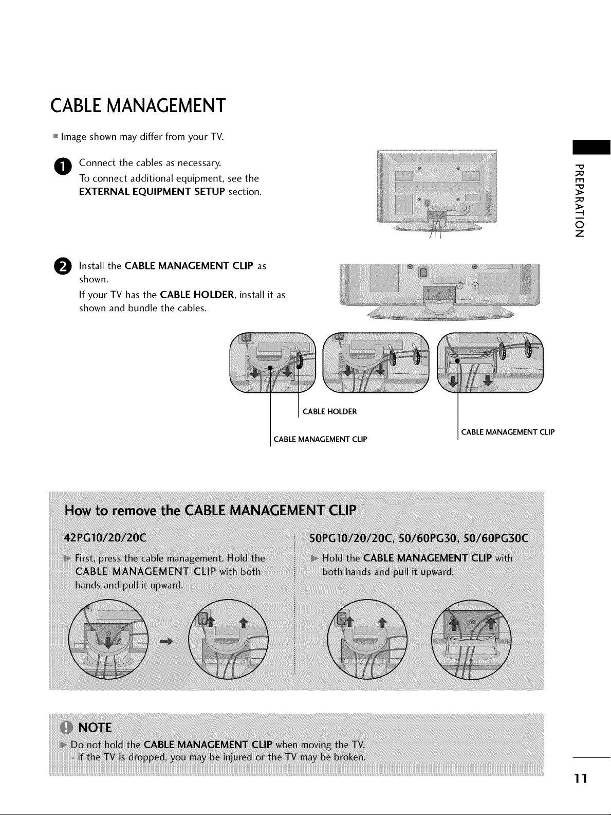
CABLEMANAGEMENT
,,,IImage shown may differ from your TV.
Connect the cables as necessary.
To connect additional equipment, see the
EXTERNAL EQUIPMENT SETUP section.
Install the CABLE MANAGEMENT CLIP as
0
shown.
If your TV hasthe CABLE HOLDER, install it as
shown and bundle the cables.
CABLE HOLDER
CABLE
MANAGEMENT CLIP
CABLEMANAGEMENT CLIP
_e
m
_e
0
z
11
PREPARATION
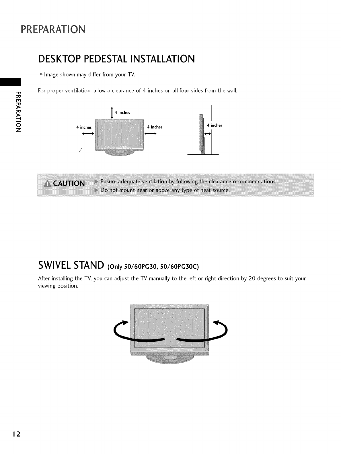
DESKTOP PEDESTALINSTALLATION
,,,IImage shown may differ from your TV.
-0
_o
m
_o
©
z
For proper ventilation, allow a clearance of 4 inches on all four sides from the wall.
4 inches
4 inches
4 inches 4 inches
SWIVELSTAND (Only 50/60PG30, 50/60PG30C)
After installing the TV, you can adjust the TV manually to the left or right direction by 20 degrees to suit your
viewing position.
12
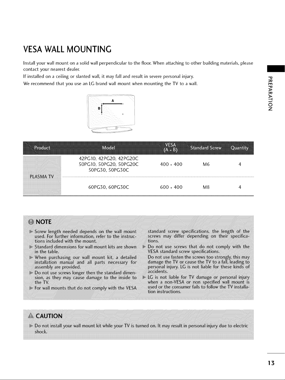
VESAWALLMOUNTING
Install your wall mount on a solid wall perpendicular to the floor. When attaching to other building materials, please
contact your nearest dealer.
If installed on a ceiling or slanted wall, it may fall and result in severe personal injury.
We recommend that you use an LG brand wall mount when mounting the TV to a wall.
42PG10, 42PG20, 42PG20C
50PG10,50PG20,50PG20C
50PG30,50PG30C
60PGS0,60PG30C 600,400 M8 4
400,400 M6 4
"O
_o
m
_o
©
z
13
PREPARATION
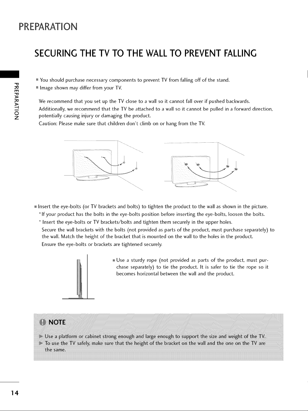
SECURING THE TV TO THE WALLTO PREVENTFALLING
-O
m
O
z
,,,IYou should purchase necessary components to prevent TV from falling off of the stand.
,,,iImage shown may differ from your TV.
We recommend that you set up the TV close to a wall so it cannot fall over if pushed backwards.
Additionally, we recommend that the TV be attached to a wall so it cannot be pulled in a forward direction,
potentially causing injury or damaging the product.
Caution: Please make sure that children don't climb on or hang from the TV.
I
Insert the eye-bolts (or TV brackets and bolts) to tighten the product to the wall as shown in the picture.
If your product has the bolts in the eye-bolts position before inserting the eye-bolts, loosen the bolts.
Insert the eye-bolts or TV brackets/bolts and tighten them securely in the upper holes.
Secure the wall brackets with the bolts (not provided as parts of the product, must purchase separately) to
the wall. Match the height of the bracket that is mounted on the wall to the holes in the product.
Ensure the eye-bolts or brackets are tightened securely.
14
01_Use a sturdy rope (not provided as parts of the product, must pur-
chase separately) to tie the product. It is safer to tie the rope so it
becomes horizontal between the wall and the product.
mTo prevent damage do not connect to the power outlet until all connections are made between the devices.
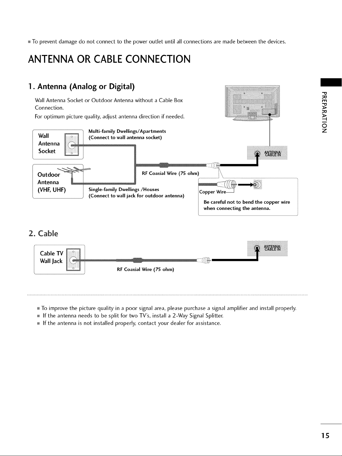
ANTENNA OR CABLECONNECTION
1. Antenna (Analog or Digital)
Wall Antenna Socket or Outdoor Antenna without a Cable Box
Connection.
For optimum picture quality, adjust antenna direction if needed.
Wall
Antenna
Socket
Outdoor
Antenna . .............. _/
VHE UHF Single-family Dwellings/Houses ..... _xr
( , HF) ] Single-family Dwellir __'__
] RF Coaxial Wire (75 ohm) I"_
J (Connect to wall jack for outdoor antenna) I H
I Be careful not to bend the copper wire
when connecting the antenna.
2. Cable
Cable TV
Wall Jack
Coaxial Wire (75 ohm)
"O
_o
r1_
_o
©
z
mTo improve the picture quality in a poor signal area, please purchase a signal amplifier and install properly.
m If the antenna needs to be split for two TV's, install a 2-Way Signal Splitter.
m If the antenna is not installed properly, contact your dealer for assistance.
15
EXTERNAL EQUIPMENT SETUP
01_To prevent the equipment damage, never plug in any power cords until you havefinished connecting allequipment.
HD RECEIVERSETUP
This TV can receive Digital Over-the-air/Cable signals without an external digital set-top box. However, if you do
receive digital signals from a digital set-top box or other digital external device, refer to the figure as shown below.
m
x
z
>
XD
c
z
c
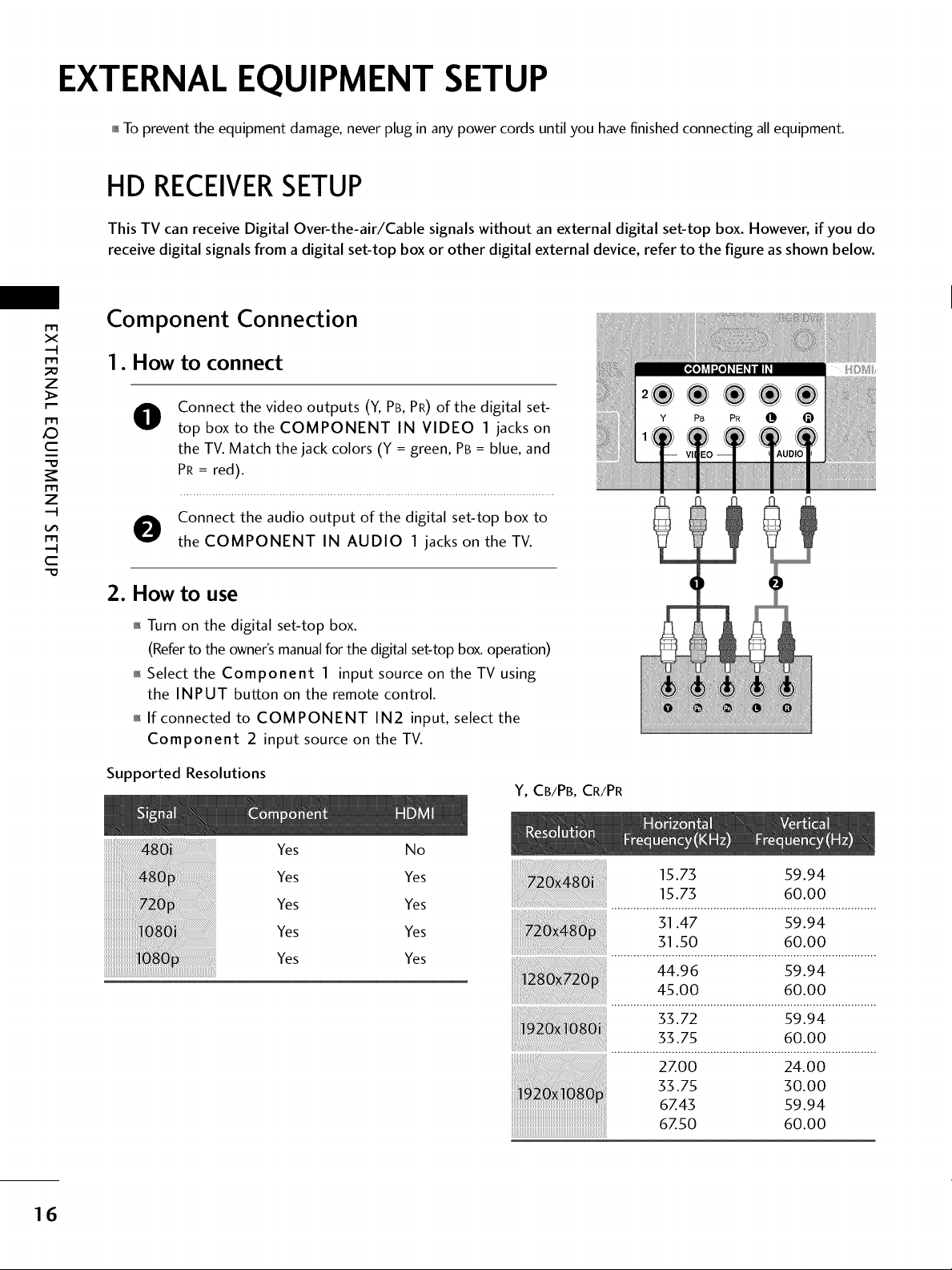
Component Connection
1. How to connect
Connect the video outputs (Y, PB, PR) of the digital set-
0
top box to the COMPONENT IN VIDEO 1 jacks on
the TV. Match the jack colors (Y = green, PB= blue, and
PR = red).
O onnect the audio output of the digital set-top box to
the COMPONENT IN AUDIO 1 jacks on the TV.
2. How to use
01_Turn on the digital set-top box.
(Referto the owner'smanualfor the digital set-topbox.operation)
0_Select the Component 1 input source on the TV using
the INPUT button on the remote control.
01_If connected to COMPONENT IN2 input, select the
Component 2 input source on the TV.
Supported Resolutions
J,i-q,lm
2®®®®
Y PB PR @
Y, CB/PB,CR/PR
16
Yes No
Yes Yes
Yes Yes
Yes Yes
Yes Yes
15.73 59.94
15.73 60.00
31.47 59.94
31.50 60.00
44.96 59.94
45.00 60.00
33.72 59.94
33.75 60.00
27.00 24.00
33.75 30.00
67.43 59.94
67.50 60.00
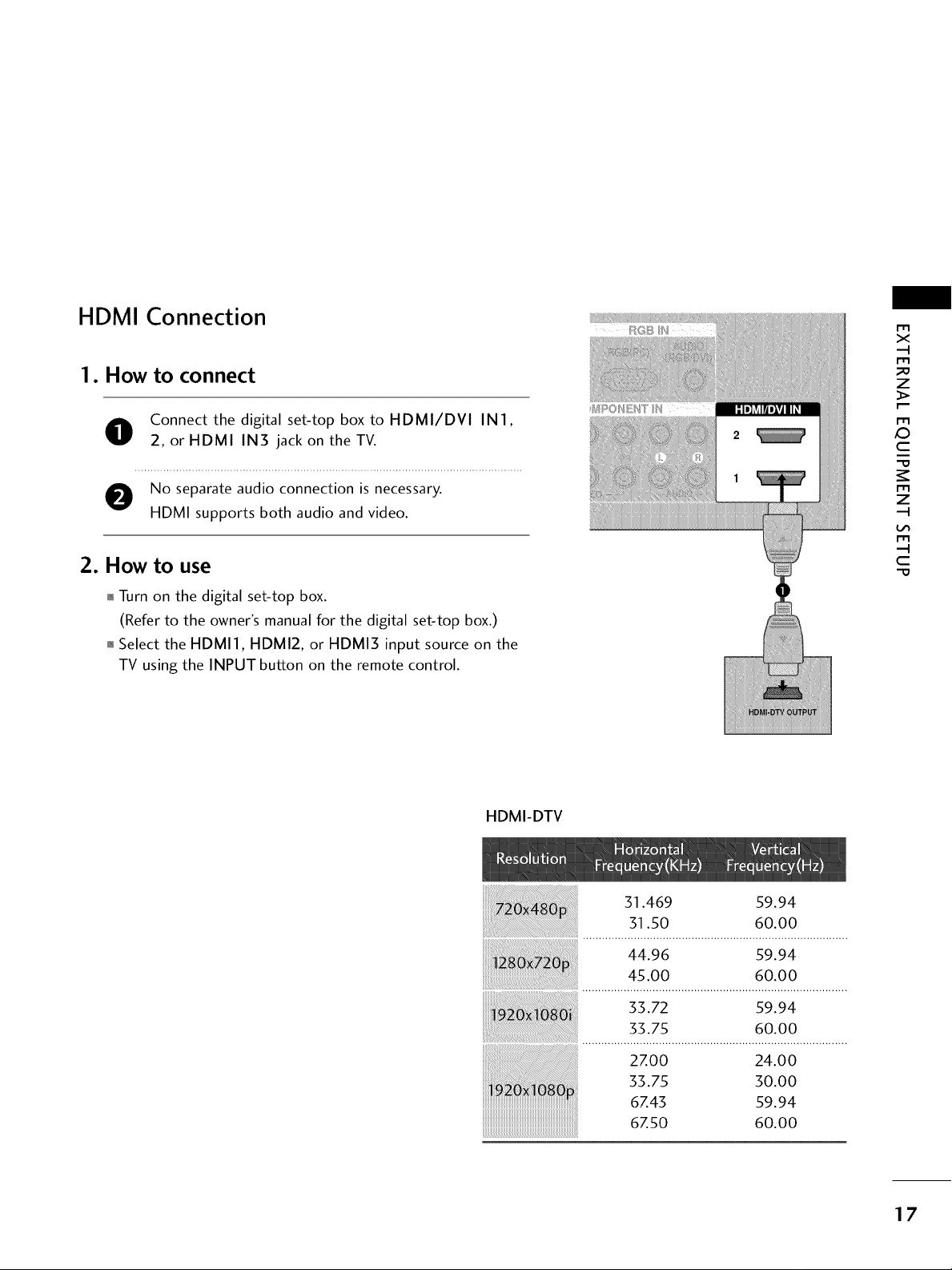
HDMI Connection
1. How to connect
O onnect the digital set-top box to HDMI/DVI IN1,
2, or HDMI IN3 jack on the TV.
e No separate audio connection is necessary.
HDMI supports both audio and video.
2. How to use
,l_Turn on the digital set-top box.
(Refer to the owner's manual for the digital set-top box.)
,l_Select the HDMI1, HDMI2, or HDMI3 input source on the
TV using the INPUT button on the remote control.
m
X
m
z
p.-
m
C
m
z
m
C
HDMI-DTV
51.469 59.94
51.50 60.00
44.96 59.94
45.00 60.00
55.72 59.94
55.75 60.00
2zoo 24.00
o.oo
6Z43 59.94
....................................................................................6Z50 60.00
17
EXTERNALEQUIPMENT SETUP
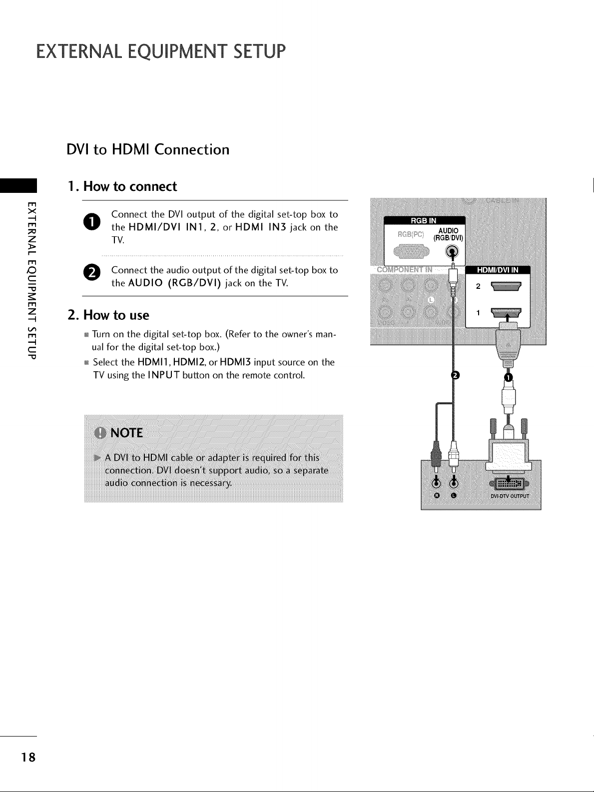
DVI to HDMI Connection
1. How to connect
m
x
m
_o
z
m
X:)
c
"O
m
z
O Connect the DVI output of the digital set-top box to
the HDMI/DVl IN1, 2, or HDMI IN5 jack on the
TV.
O Connect the audio output of the digital set-top box to
the AUDIO (RGB/DVI) jack on the TV.
2. How to use
m
c
"O
01_Turn on the digital set-top box. (Refer to the owner's man-
ual for the digital set-top box.)
01_Select the HDMI1, HDMI2, or HDMI3 input source on the
TV using the INPUT button on the remote control.
18
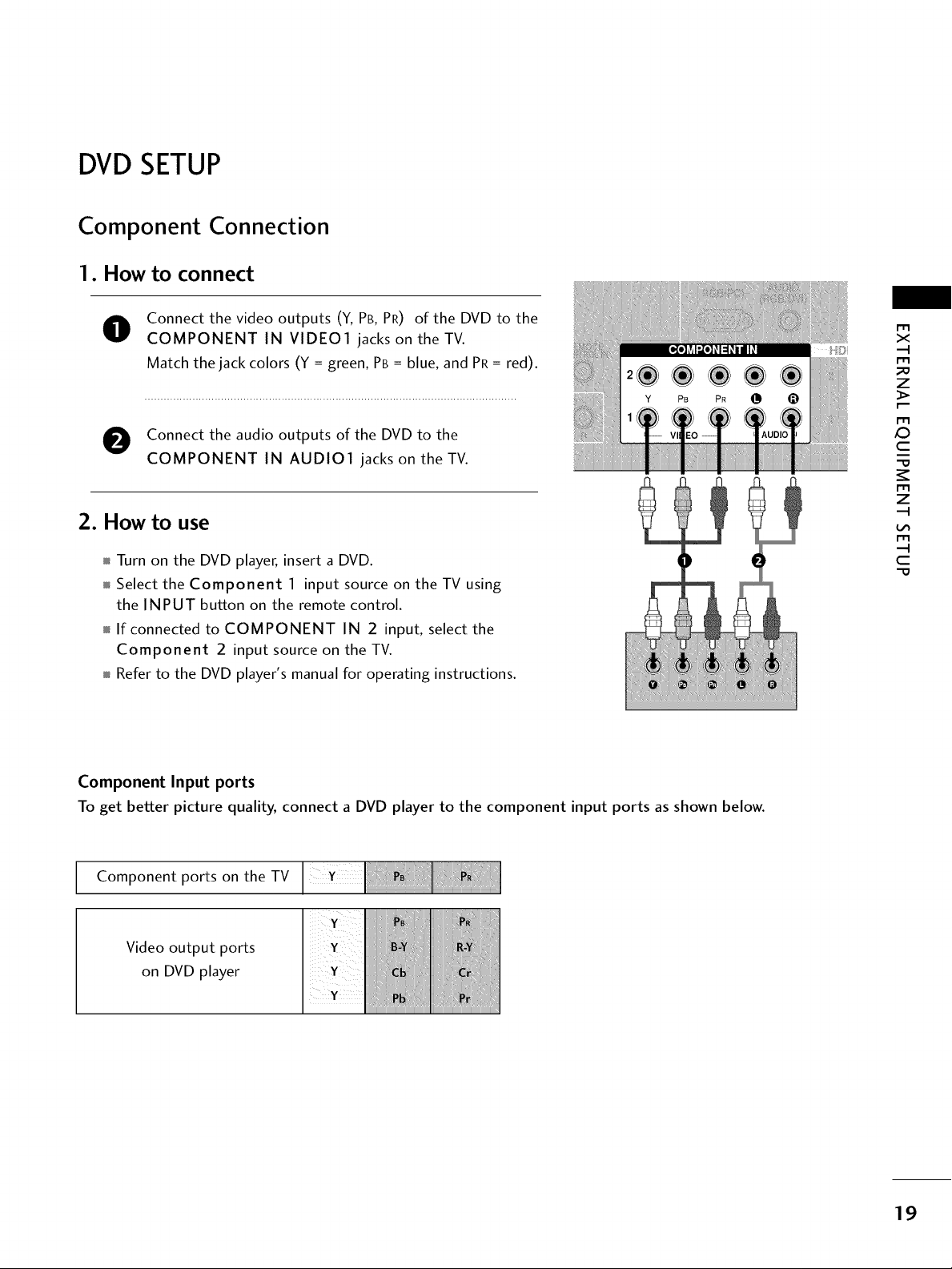
DVDSETUP
Component Connection
1. How to connect
Connect the video outputs (Y, PB, PR) of the DVD to the
O
COMPONENT IN VIDE01 jacks on the TV.
Match the jack colors (Y = green, PB = blue, and PR = red).
O Connect the audio outputs of the DVD to the
COMPONENT IN AUDIO1 jacks on the TV.
2. How to use
Turn on the DVD player, insert a DVD.
Select the Component 1 input source on theTVusing
the INPUT button on the remote control.
If connected to COMPONENT IN 2 input, select the
Component 2 input source on the TV.
Refer to the DVD player's manual for operating instructions.
x
m
z
m
XD
c
m
z
m
c
Component Input ports
To get better picture quality, connect a DVD player to the component input ports as shown below.
Component ports on the TV
Video output ports
on DVD player
19
EXTERNALEQUIPMENT SETUP
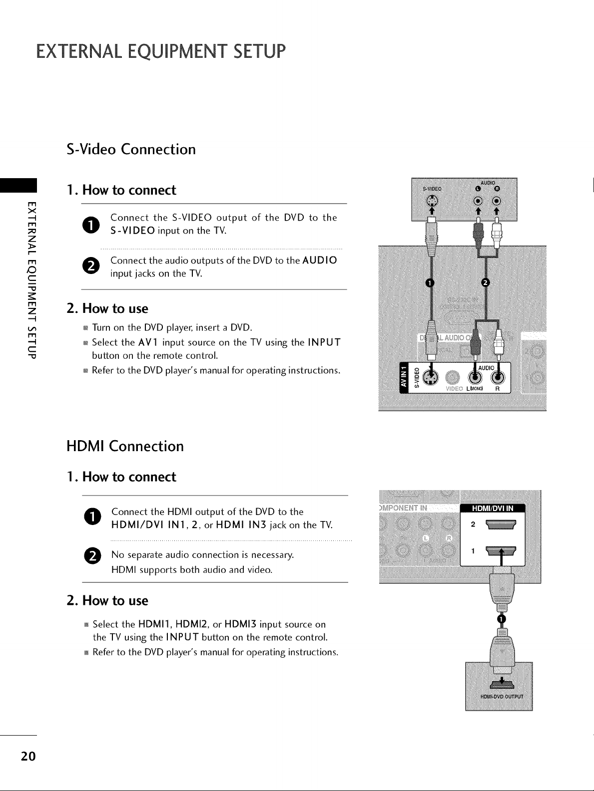
S-Video Connection
1. How to connect
m
x
O Connect the S-VIDEO output of the DVD to the
z
S-VIDEO input on the TV.
X:)
c
z
c
"O
Connect the audio outputs of the DVD to the AUDIO
input jacks on the TV.
2. How to use
01_Turn on the DVD player, insert a DVD.
,l_Select the AV1 input source on the TV using the INPUT
button on the remote control.
01_Refer to the DVD player's manual for operating instructions.
HDMI Connection
1. How to connect
O Connect the HDMI output of the DVD to the
HDMI/DVI IN1,2, or HDMI IN3 jack on the TV.
e No audio connection is
separate necessary.
HDMI supports both audio and video.
2O
2. How to use
,l_Select the HDMI1, HDMI2, or HDMI3 input source on
the TV using the INPUT button on the remote control.
01_Refer to the DVD player's manual for operating instructions.
VCRSETUP
To avoid picture noise (interference), leave an adequate distance between the VCR and TV.
Use the ISM feature in the Option menu to avoid having a fixed image remain on the screen for a long period
of time. If the 4:3 picture format is used; the fixed images on the sides of the screen may remain visible on
the screen. This phenomenon is common to all TVs and is not covered by warranty.
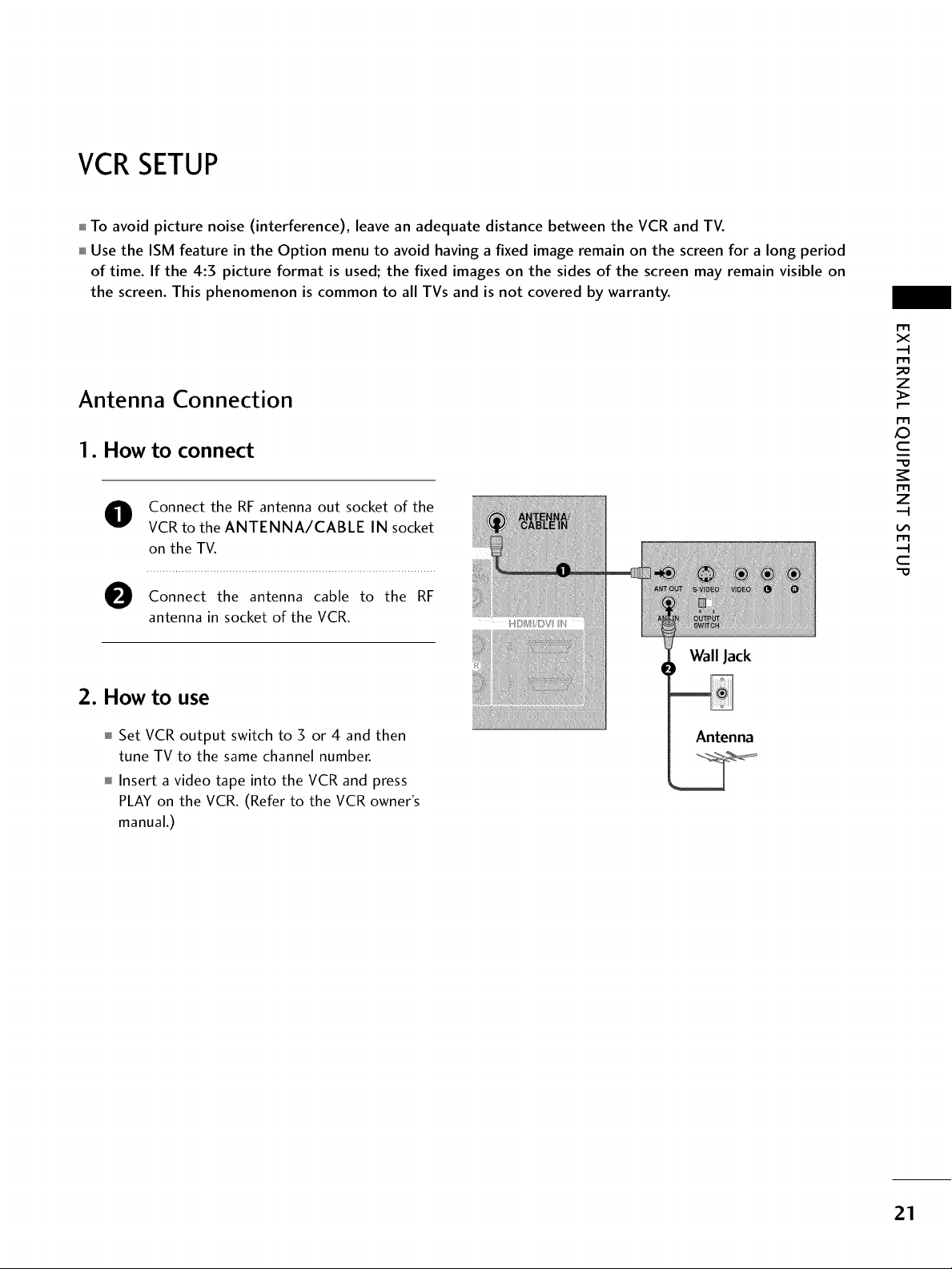
Antenna Connection
1. How to connect
O Connect the RF antenna out socket of the
VCR to the ANTENNA/CABLE IN socket
on the TV.
Connect the antenna cable to the RF
antenna in socket of the VCR.
X_
m
x
z
c
z
c
"0
2. How to use
Set VCR output switch to 3 or 4 and then
tune TV to the same channel number.
Insert a video tape into the VCR and press
PLAY on the VCR. (Refer to the VCR owner's
manual.)
Wall Jack
21
EXTERNALEQUIPMENT SETUP
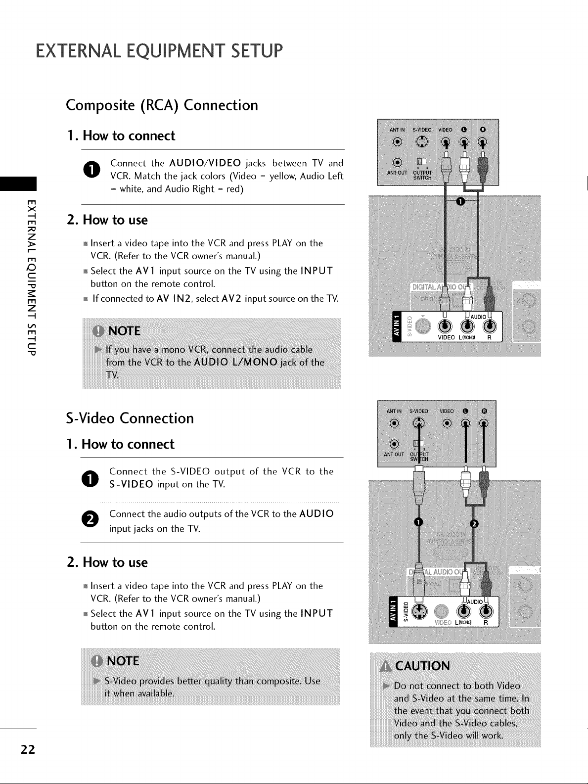
Composite (RCA) Connection
1. How to connect
Connect the AUDIO/VIDEO jacks between TV and
VCR. Match the jack colors (Video = yellow, Audio Left
= white, and Audio Right = red)
x
_o
z
X:)
c
z
2. How to use
01_Insert a video tape into the VCR and press PLAY on the
VCR. (Refer to the VCR owner's manual.)
01_Select the AVl input source on the TV using the INPUT
button on the remote control.
01_If connected to AV IN2, select AV2 input source on the TV.
c
"O
S-Video Connection
1. How to connect
Connect the S-VIDEO output of the VCR to the
S-VIDEO input on the TV.
Connect the audio outputs of the VCR to the AUDIO
input jacks on the TV.
2. How to use
01_Insert a video tape into the VCR and press PLAY on the
VCR. (Refer to the VCR owner's manual.)
01_Select the AVl input source on the TV using the INPUT
button on the remote control.
22
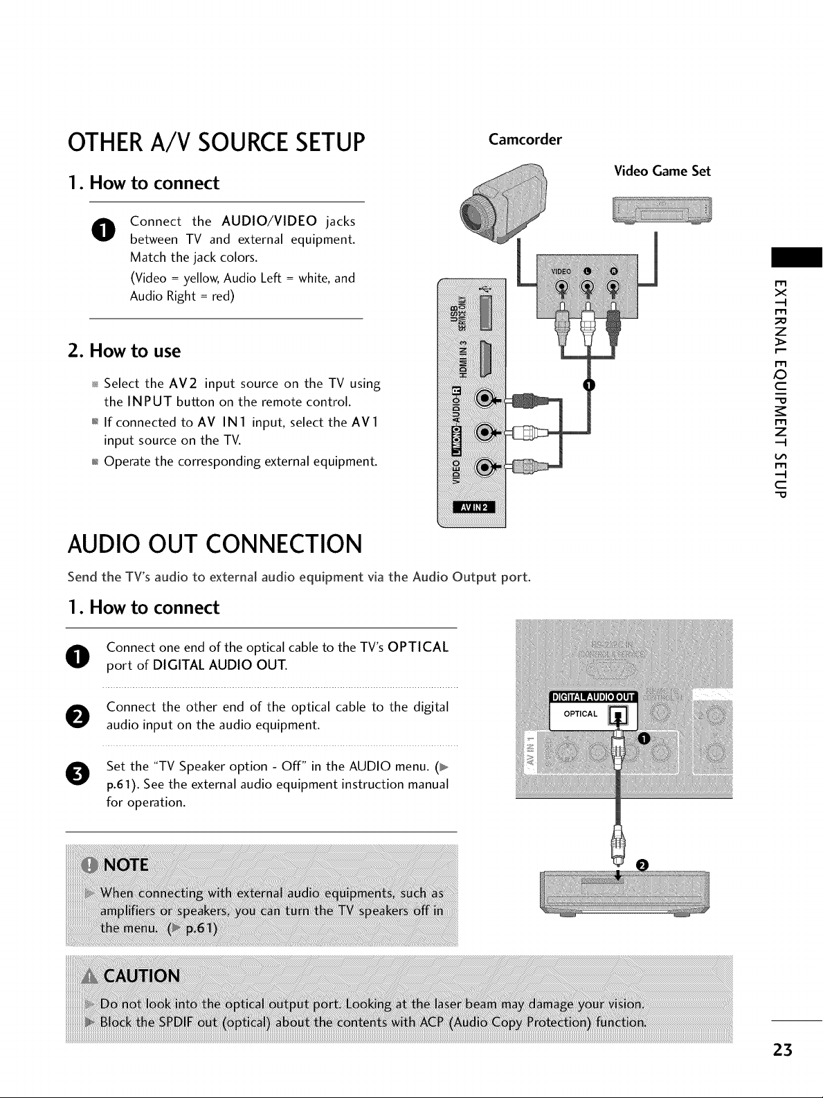
OTHERA/V SOURCESETUP
Camcorder
1. How to connect
Connect the AUDIO/VIDEO jacks
O
between TV and external equipment.
Match the jack colors.
(Video = yellow, Audio Left = white, and
Audio Right = red)
2. How to use
Select the AV2 input source on the TV using
the INPUT button on the remote control.
01_If connected to AV IN I input, select the AV I
input source on the TV.
01_Operate the corresponding external equipment.
AUDIO OUT CONNECTION
Video Game Set
r_3
x
_o
z
r_3
XD
c
"O
z
c
-O
Send the TV's audio to external audio equipment via the Audio Output port.
1. How to connect
O Connect one end of the optical cable to the TV's OPTICAL
port of DIGITAL AUDIO OUT.
O onnect the other end of the optical cable to the digital
audio input on the audio equipment.
O Set the "TV Speaker option - Off" in the AUDIO menu. (_
p.61). See the external audio equipment instruction manual
for operation.
23

EXTERNALEQUIPMENT SETUP
PCSETUP
This TV provides Plug and Play capability, meaning that the PC adjusts automatically to the TV's settings.
VGA (D-Sub 15 pin) Connection
1. How to connect
r_3
x
_o
z
O onnect the VGA output of the PC to the RGB (PC)
jack on the TV.
r_3
X:)
c
"O
z
c
-O
O Connect the PC audio output to the AUDIO
(RGB/DVI) jack on the TV.
2. How to use
01_Turn on the PC and the TV.
01_Select the RGB-PC input source on the TV using the
INPUT button on the remote control.
DVI to HDMI Connection
1. How to connect
O onnect the DVIoutput of the PCto the HDMI/DVI
IN 1, 2, or HDMI IN3 jack on the TV.
24
O Connect the PC audio output to the AUDIO
(RGB/DVI) jack on the TV.
2. How to use
01_Turn on the PC and the TV.
01_Select the HDMII, HDMI2 or HDMI3 input source on the
TV using the INPUT button on the remote control.
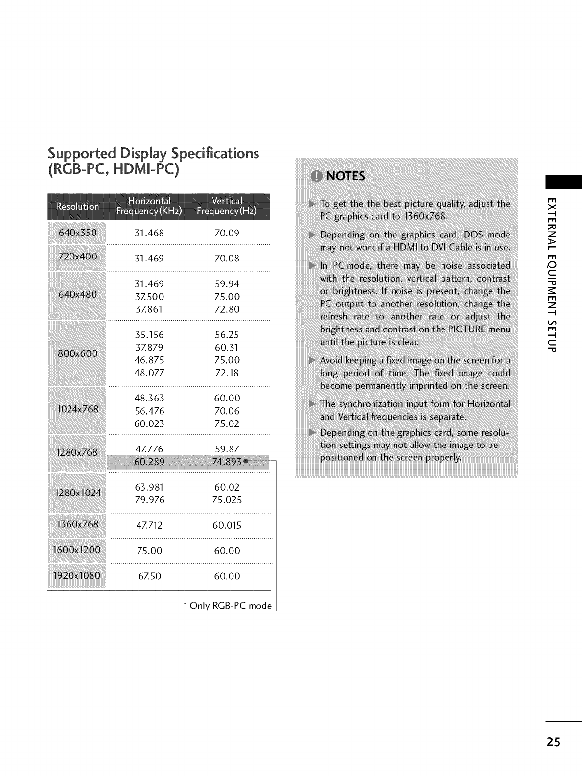
Supported DispJay Specifications
(RCB-PC,HDMm-PC)
31.468 70.09
m
X
m
z
31.469 70.08
31.469 59.94
3Z500 75.00
3Z861 72.80
35.156 56.25
3Z879 60.31
46.875 75.00
48.077 72.18
48.363 60.00
56.476 70.06
60.023 75.02
4Z776 59.87
63.981 60.02
79.976 75.025
4Z712 60.015
m
_D
C
m
z
m
C
75.00 60.00
6, o 6ooo
* Only RGB-PC mode
25
EXTERNALEQUIPMENT SETUP
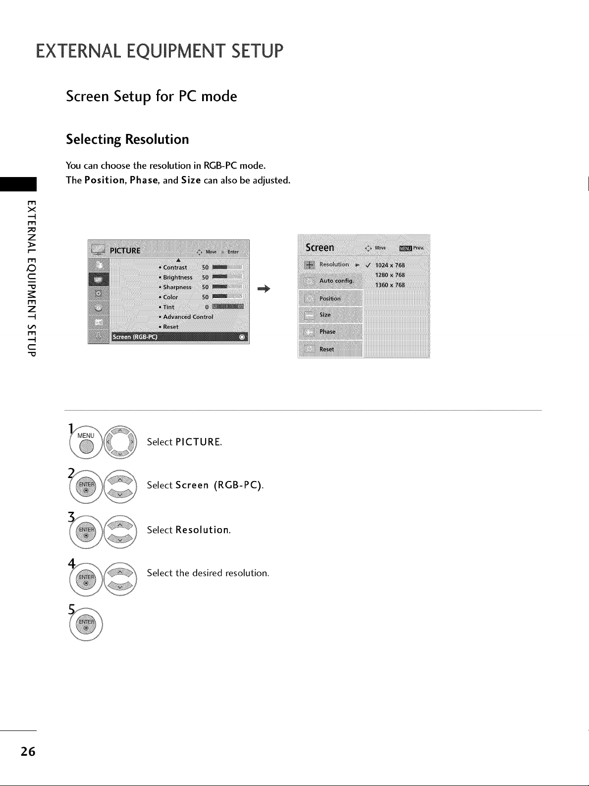
Screen Setup for PC mode
Selecting Resolution
You can choose the resolution in RGB-PC mode.
The Position, Phase, and Size can also be adjusted.
m
x
m
_o
z
m
X:)
c
m
z
m
c
"0
iiIii_iiiiii!i_iiii!iii!ii!i!M!ii!iiiii!i!ii!i!i_i_iiiiiiiiiiiiiiiiiiiiiiiiiiiiiiiiiiiiiiiiiiiiiiiiiiiiiiiiiiiiiiiiiiiiiiiiiiiiiiiiiiiiiiiiiii
Select PICTURE.
Select Screen (RGB-PC).
Select Resolution.
Select the desired resolution.
26

Auto Configure
Automatically adjusts picture position and minimizes image instability. After adjustment, if the image is still
not correct, try using the manual settings or a different resolution or refresh rate on the PC.
r'_
x
m
z
m
c
m
z
m
c
Select PICTURE.
Select Screen (RGB-PC).
Select Auto config..
Select Yes.
Start Auto Configuration.
• If the position of the image is still not
correct, try Auto adjustment again.
• If picture needs to be adjusted again
after Auto adjustment in RGB-PC, you
can adjust the Position, Size or
Phase.
27
EXTERNALEQUIPMENT SETUP
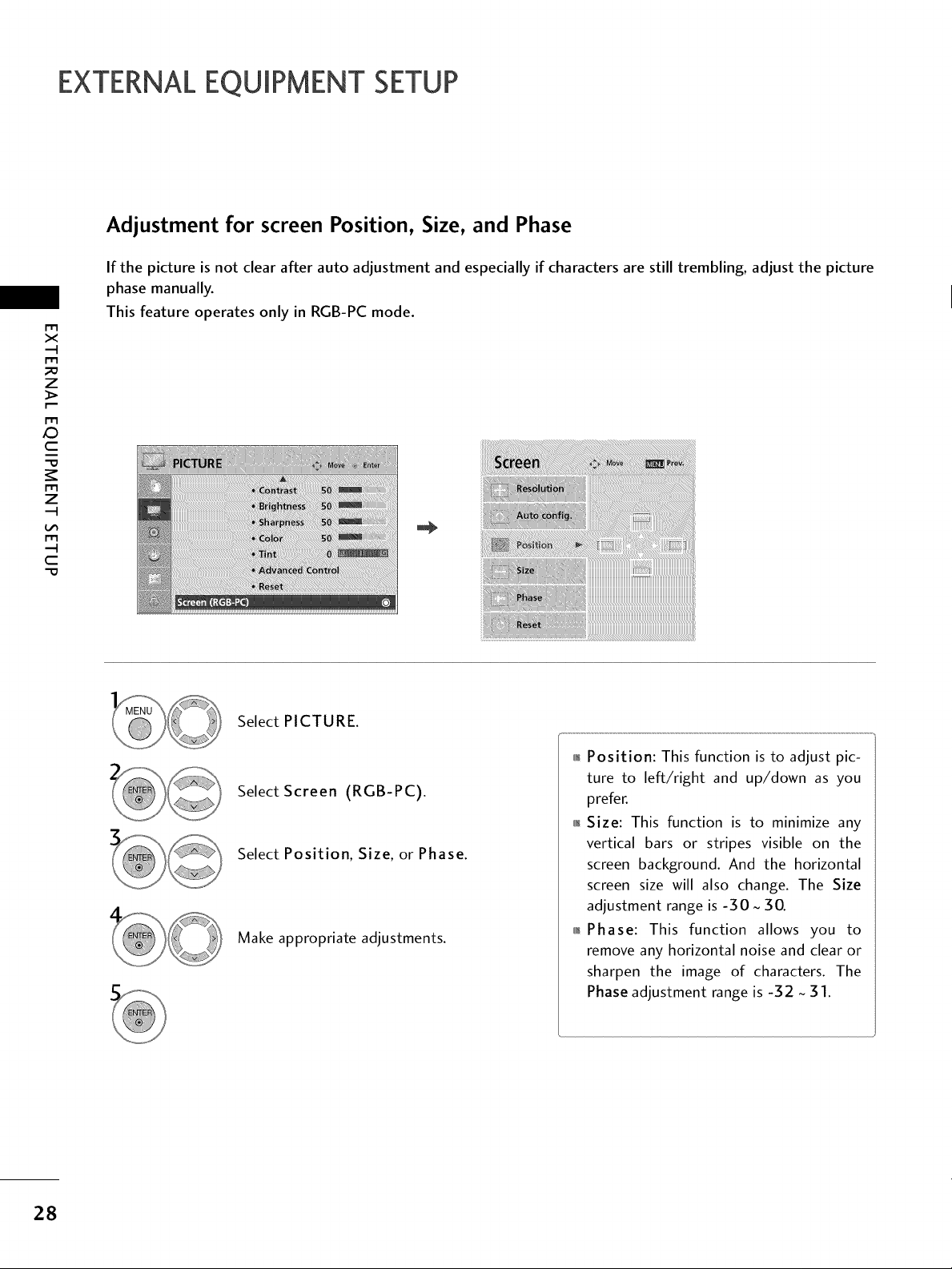
Adjustment for screen Position, Size, and Phase
If the picture is not clear after auto adjustment and especially if characters are still trembling, adjust the picture
phase manually.
m
x
m
z
m
_D
c
m
z
m
c
This feature operates only in RGB-PC mode.
Select PICTURE.
Select Screen (RGB-PC).
Select Position, Size, or Phase.
Make appropriate adjustments.
_ Position: This function is to adjust pic-
ture to left/right and up/down as you
prefer.
_ Size: This function is to minimize any
vertical bars or stripes visible on the
screen background. And the horizontal
screen size will also change. The Size
adjustment range is -30 ~ 30.
_ Phase: This function allows you to
remove any horizontal noise and clear or
sharpen the image of characters. The
Phase adjustment range is -32 ~ 31.
28
 Loading...