

Page 1

01-14-2016
SMPS Trouble LED blinks 3 times
then
only 2 times
Alvie Rod
60LB7100 Intermittent Backlights
LG Electronics Training Center, LGEAI, U.S.A.
• Backlights Blink
• Backlights go off
•
• Note: This panel was a Refurbished panel from parts.
01-14-2016 ver 3
gers C.E.T.
.
Page 2

Situation During Testing:
completely
for backlight grounding signals, all but two test points were reading approximately 4V. But
But t
(EL55
EL64). Backlight P
56V
Installed a Refurbished panel from Parts into our 60LB7100.
Panel P/N: CRD31515701
TV ran for 4 days, 24 hours a day until symptom showed up.
Findings:
• The backlights would begin to blink. Usually 4 to 6 times then they would shut off
.
• SMPS LED was blinking 2 times indicating DC-to-DC converter problem.
• However, when watching the SMPS trouble LED while the backlights were blinking, it
blinked 3 times once or twice then it went to 2 times after the backlights went off. 3 times
indicating Open LEDs.
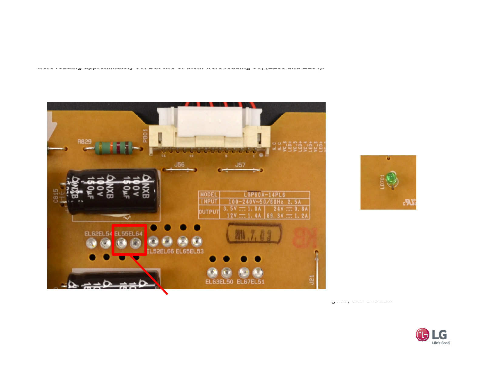
• While Backlights were blinking: Reading the test points EL50-EL54 EL62-EL67 on the SMPS
two of them were reading 0V, (EL55 and EL64). Backlight Power was 70V.
60LB7100 Intermittent Backlights
• While Backlights were off: Reading the test points EL50-EL54 EL62-EL67 on the SMPS for
backlight grounding signals, all but two test points were reading approximately 7V.
wo of them were reading 0V,
and
ower was
• Note: In this model there are only 6 backlight drivers. So two test points are tied together
per/driver.
• See next page for further details
01-14-2016
2
.
Page 3
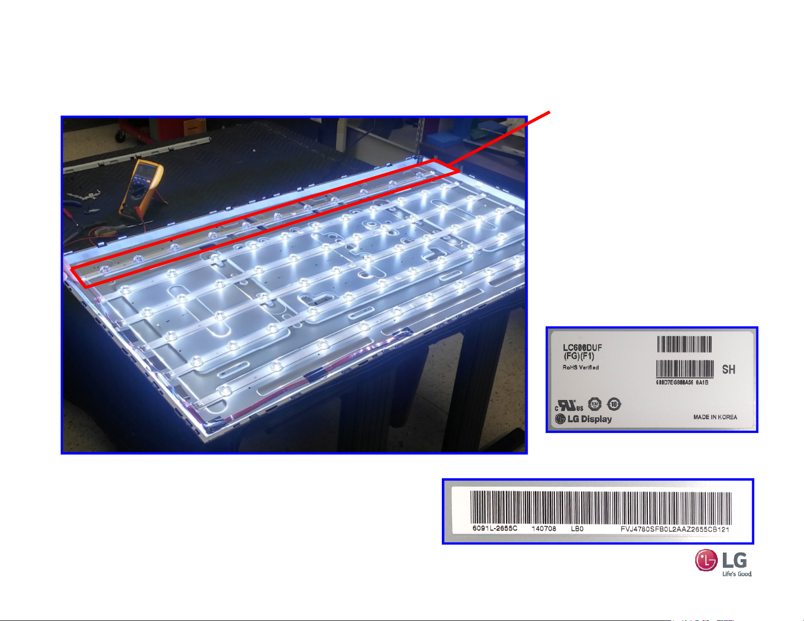
Panel Issue:
Panel’s bottom Backlight Bar was intermittent.
60LB7100 Intermittent Backlights
The Backlight bar at
the bottom of the panel
is the issue.
Connector (Top Left in
this picture was the
problem.
Panel Label
01-14-2016
Backlight Structure Bar Code
3
Page 4
60LB7100 Intermittent Backlights
were reading approximately 6V. But two of them were reading 0V, (EL55 and EL64).
T
(EL55
EL64)
good, SMPS is bad.
Test Point Checks
Reading the test points EL50-EL54 EL62-EL67 on the SMPS for backlight grounding signals, all but two test points
Note: In this model there are only 6 backlight drivers. So two test points are tied together per/driver.
Example: EL62 and EL54 are tied together, EL55, EL64 are tied together, etc….
Note: When the Backlights are “off”, the reading are 2V on good LED bars and “0V” on the defective bar.
LED (LD701) would blink 3 times
while backlights were blinking
and 2 times after the backlights
turned off.
wo test points reading 0V,
This test indicates “Open” Backlight LEDs.
A reading of 20V (High) would indicate an open
01-14-2016
driver, see note on the right.
and
.
4
Note: LED (LD701) blinking 3 times
indicates an open backlight LED
feedback line.
Check the Test points EL50-EL54
EL62-EL67 for “20V” volts. This
would indicate an Open LED driver.
Using a 100 ohm resistor, one end
to ground, touch the other end to
the Test Point pin that has “20V”. If
the backlight comes on, the panel is
Page 5
60LB7100 Intermittent Backlights
i
(B+) to the b
ittent
Problem:
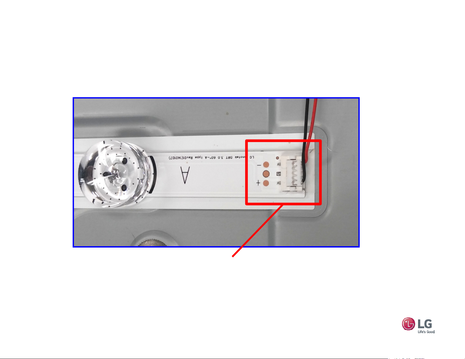
After disassembling the panel, we found that the connector to the bottom LED Bar was intermittent. The connector
s attached by simply pressing it down onto the connector. The Red wire
contact with the connections on the LED Bar. On all “A” bars, LED B+ arrives on the (-) marked pin on the
connector. On all “B” bars, LED B+ arrives on the (+) marked pin.
ar was interm
making
Top (Red Wire) connection was intermittent.
“Open” Backlight LEDs.
A slight movement of the red wire caused the LEDs to turn off or on.
01-14-2016
5
Page 6
60LB7100 Intermittent Backlights
F
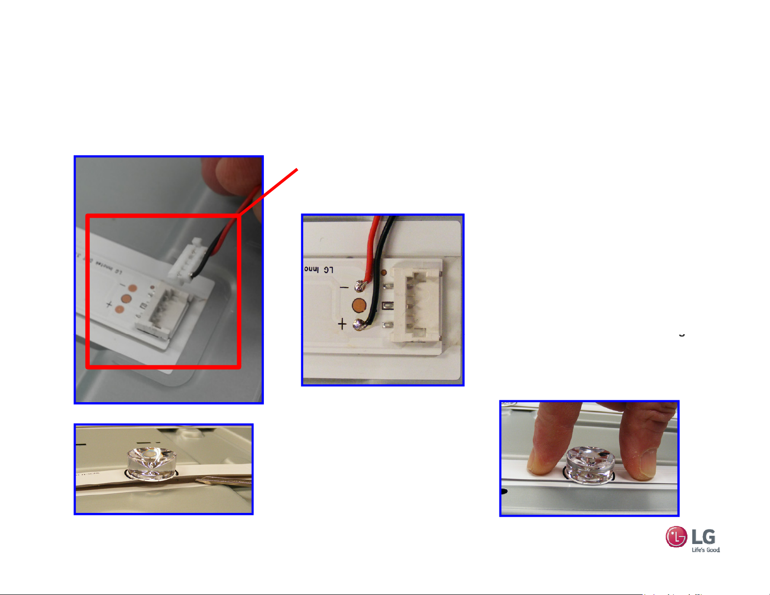
and solder them directly to the LED
g
If they have, press down on either side
Possible Internal Correction:
This connector is inserted by laying it over the connector on the board and pressing down to press it into place.
or those unable to do panel disassembly, panel replacement is necessary.
Repair of this connector (by removing the wire and trying to
tighten the connection) would be difficult.
In my opinion, the best repair method
for this would be to remove the wires
bar.
Avoid solder bridges. Cut the crimped
connector off the wire first.
For permanent fix, you should do this
to all “outside” connectors on the right
and the left side of the LED Bars.
Note: You may need to un-tape the
wire harness to allow for slack. Be sure
to re-tape after repair.
01-14-2016
Examine each LED to make sure they
have not become un-bonded. “Do not
life by the LED lens”. Over time, this
could cause overheating.
of the LED for about 60 seconds to rebond. Do not press down on LED.
6
 Loading...