

LG 56DC1DUC User Manual

© Copyright 2005, LG Electronics USA, Inc.
Installation and Operating Guide | Warranty
Model Numbers | Z56DC1D/Z62DC1D | DLP PROJECTION
2 DLP Projection TV
WARNING/CAUTION:
TO REDUCE THE RISK OF ELECTRIC SHOCK DO NOT REMOVE COVER (OR BACK). NO USER
SERVICEABLE PARTS INSIDE. REFER TO QUALIFIED SERVICE PERSONNEL.
The lightning flash with arrowhead symbol, within an equilateral triangle, is intended to alert the user to
the presence of uninsulated “dangerous voltage” within the product’s enclosure that may be of sufficient magnitude to constitute a risk of electric shock to persons.
The exclamation point within an equilateral triangle is intended to alert the user to the presence of
important operating and maintenance (servicing) instructions in the literature accompanying the appliance.
WARNING/CAUTION:
TO PREVENT FIRE OR SHOCK HAZARDS, DO NOT EXPOSE THIS PRODUCT TO RAIN OR MOISTURE.
POWER CORD POLARIZATION:
CAUTION: TO PREVENT ELECTRIC SHOCK, MATCH WIDE BLADE OF PLUG TO WIDE SLOT, FULLY
INSERT.
ATTENTION: POUR ÉVITER LES CHOCS ÉLECTRIQUES, INTRODUIRE LA LAME LA PLUS LARGE
DE LA FICHE DANS LA BORNE CORRESPONDANTE DE LA PRISE ET POUSSER JUSQU’AU FOND.
NOTE TO CABLE/TV INSTALLER:
This reminder is provided to call the CATV system installer’s attention to Article 820-40 of the National
Electric Code (U.S.A.). The code provides guidelines for proper grounding and, in particular, specifies that
the cable ground shall be connected to the grounding system of the building, as close to the point of the
cable entry as practical.
REGULATORY INFORMATION:
This equipment has been tested and found to comply with the limits for a Class B digital device, pursuant to Part
15 of the FCC Rules. These limits are designed to provide reasonable protection against harmful interference in
a residential installation. This equipment generates, uses and can radiate radio frequency energy and, if not
installed and used in accordance with the instructions, may cause harmful interference to radio communications.
However, there is no guarantee that interference will not occur in a particular installation. If this equipment does
cause harmful interference to radio or television reception, which can be determined by turning the equipment off
and on, the user is encouraged to try to correct the interference by one or more of the following measures:
- Reorient or relocate the receiving antenna.
- Increase the separation between the equipment and receiver.
- Connect the equipment into an outlet on a circuit different from that to which the receiver is connected.
- Consult the dealer or an experienced radio/TV technician for help.
Any changes or modifications not expressly approved by the party responsible for compliance could void the
user’s authority to operate the equipment.
CAUTION:
Do not attempt to modify this product in any way without written authorization from LG Electronics. Unauthorized modification could void the user’s authority to operate this product.
COMPLIANCE:
The responsible party for this product’s compliance is:
Zenith Electronics Corporation
1-201-816-2000
Marked and Distributed in the United States by LG Electronics U.S.A., Inc.
1000 Sylvan Avenue, Englewood Cliffs, NJ 07632
http://www.zenith.com
WARNING
RISK OF ELECTRIC SHOCK
DO NOT OPEN
/CAUTION
W
W
arning/Caution
arning/Caution
Warning/Caution
Owner’s Manual 3
Safety Instructions
IMPORTANT SAFETY INSTRUCTIONS
Important safety instructions shall be provided with each apparatus. This information shall be given in a separate booklet or
sheet, or be located before any operating instructions in an instruction for installation for use and supplied with the apparatus. This information shall be given in a language acceptable to the country where the apparatus is intended to be used. The
important safety instructions shall be entitled “Important Safety Instructions”. The following safety instructions shall be included where applicable, and, when used, shall be verbatim as follows. Additional safety information may be included by adding
statements after the end of the following safety instruction list. At the manufacturer’s option, a picture or drawing that illustrates the intent of a specific safety instruction may be placed immediately adjacent to that safety instruction :
1. Read these instructions.
2. Keep these instructions.
3. Heed all warnings.
4. Follow all instructions.
5. Do not use this apparatus near water.
6. Clean only with dry cloth.
7. Do not block any ventilation openings. Install in accordance with the manufacturer’s instructions.
8. Do not install near any heat sources such as radiators, heat registers, stoves, or other apparatus (including ampli-
fiers)that produce heat.
9. Do not defeat the safety purpose of the polarized or grounding-type plug. A polarized plug has two blades with
one wider than the other. A grounding type plug has two blades and a third grounding prong, The wide blade or the
third prong are provided for your safety. If the provided plug does not fit into your outlet, consult an electrician for
replacement of the obsolete outlet.
10. Protect the power cord from being walked on or pinched particularly at plugs, convenience receptacles, and the
point where they exit from the apparatus.
11. Only use attachments/accessories specified by the manufacturer.
12. Use only with the cart, stand, tripod, bracket, or table specified by the manufacturer, or sold with the apparatus.
When a cart is used, use caution when moving the cart/apparatus combination to avoid injury from tip-over.
Safety Instructions
Safety Instructions
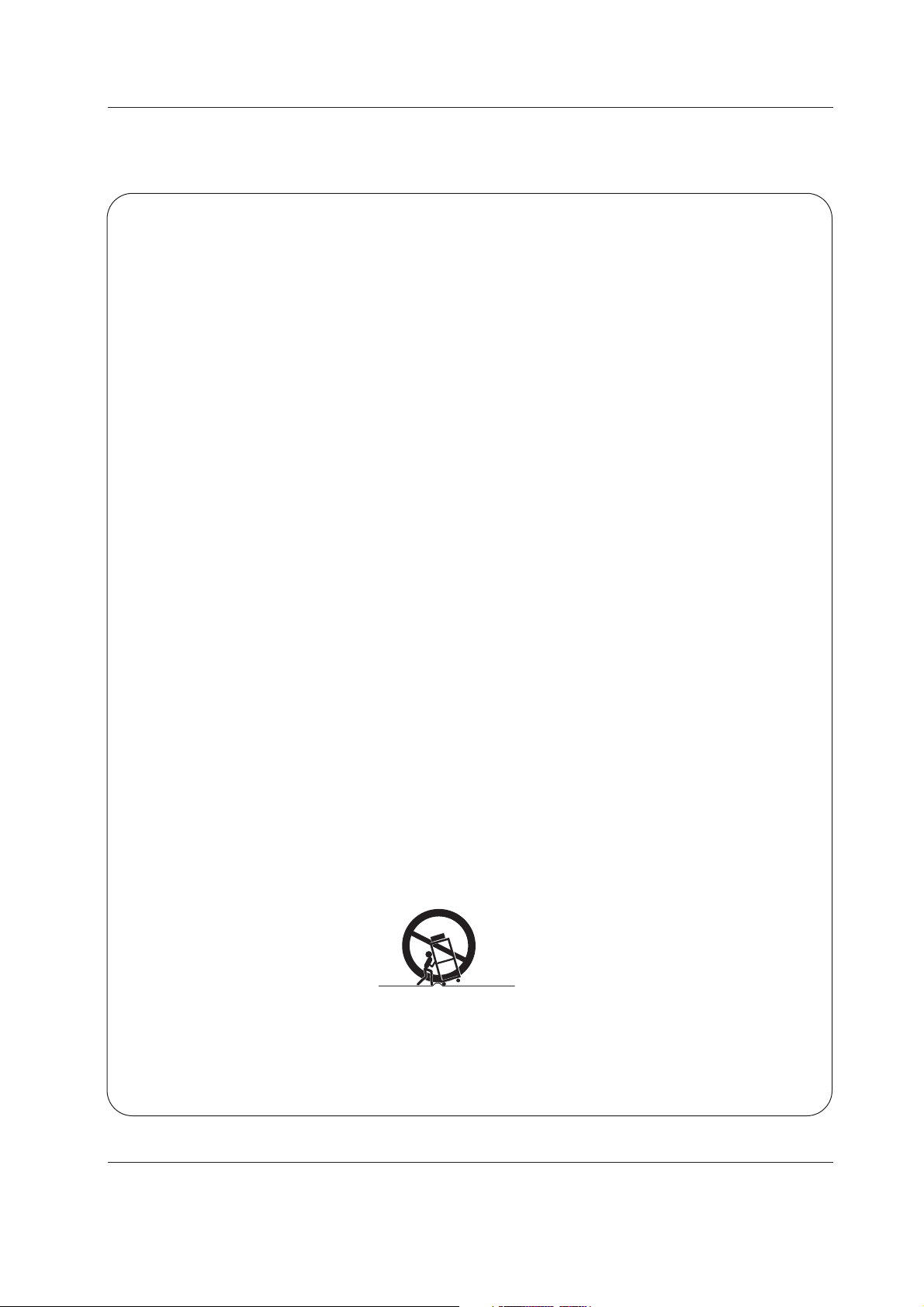
PORTABLE CART WARNING

4 DLP Projection TV
Safety Instructions
13. Unplug this apparatus during lightning storms or when unused for long periods of time.
14. Refer all servicing to qualified service personnel. Servicing is required when the apparatus has been damaged
in any way, such as power-supply cord or plug is damaged, liquid has been spilled or objects have fallen into
the apparatus, the apparatus has exposed to rain or moisture, does not operate normally, or has been dropped.
15. CAUTION concerning the Power Cord :
Most appliances recommend they be placed upon a dedicated circuit; that
is, a single outlet circuit which powers only that appliance and has no
additional outlets or branch circuits. Check the specification page of
this owner's manual to be certain.
Do not overload wall outlets. Overloaded wall outlets, loose or damaged
wall outlets, extension cords, frayed power cords, or damaged or
cracked wire insulation are dangerous. Any of these conditions could
result in electric shock or fire. Periodically examine the cord of your
appliance, and if its appearance indicates damage or deterioration,
unplug it, discontinue use of the appliance, and have the cord replaced
with an exact replacement part by an authorized servicer.
Protect the power cord from physical or mechanical abuse, such as being
twisted, kinked, pinched, closed in a door, or walked upon. Pay
particular attention to plugs, wall outlets, and the point where the
cord exits the appliance.
16. Outdoor Use Marking :
WARNING - To Reduce The Risk Of Fire Or Electric Shock, Do Not Expose This Appliance To Rain Or Moisture.
17. Wet Location :
Apparatus shall not be exposed to dripping or splashing and no objects filled with liquids, such as vases, shall
be placed on the apparatus.

Owner’s Manual 5
Contents
After reading this manual, keep it handy for future reference.
Warnings/Caution . . . . . . . . . . . . . . . . . . . . . . . . . . . . . . .2
Safety Instructions . . . . . . . . . . . . . . . . . . . . . . . . . . . . .3~4
Introduction
Controls . . . . . . . . . . . . . . . . . . . . . . . . . . . . . . .6
Connection Options . . . . . . . . . . . . . . . . . . . .7~8
Remote Control Key Functions . . . . . . . . . . .9~10
Installation
External Equipment Connections . . . . . . . . . .11~16
Antenna or Cable Connection . . . . . . . . . . . . . .11
VCR Setup . . . . . . . . . . . . . . . . . . . . . . . . . . .12
External A/V Source Setup . . . . . . . . . . . . . . . .13
DVD Setup . . . . . . . . . . . . . . . . . . . . . . . . . . . .13
HDSTB Setup . . . . . . . . . . . . . . . . . . . . . . . . . .14
Monitor Out Setup . . . . . . . . . . . . . . . . . . . . . .14
PC Setup . . . . . . . . . . . . . . . . . . . . . . . . . . . . .15
Digital Audio Output . . . . . . . . . . . . . . . . . . . . .16
External Stereo . . . . . . . . . . . . . . . . . . . . . . . . .16
HDMI . . . . . . . . . . . . . . . . . . . . . . . . . . . . .17~19
Operation
Turning the TV On . . . . . . . . . . . . . . . . . . . . . .20
TV Setup
On-screen Menus Language Selection . . . . . . .21
Setup Menu Options
EZ Scan (Channel Search) . . . . . . . . . . . . . . . .22
Channel Edit . . . . . . . . . . . . . . . . . . . . . . . . . . .22
Channel Label Setup . . . . . . . . . . . . . . . . . . . .23
Main Picture Source Selection . . . . . . . . . . . . .23
Input Label . . . . . . . . . . . . . . . . . . . . . . . . . . . .23
Video Menu Options
EZ Picture . . . . . . . . . . . . . . . . . . . . . . . . . . . .24
Manual Picture Control (Custom Option) . . . . . .24
Color Temperature Control . . . . . . . . . . . . . . . .24
Video Reset . . . . . . . . . . . . . . . . . . . . . . . . . . .24
Audio Menu Options
Audio Language . . . . . . . . . . . . . . . . . . . . . . . .25
EZ SoundRite / EZ Sound . . . . . . . . . . . . . . . . .25
Manual Sound Control (Custom Option) . . . . . .25
Front Surround . . . . . . . . . . . . . . . . . . . . . . . . .26
TV Speakers On/Off Setup . . . . . . . . . . . . . . . .26
Stereo/SAP Broadcasts Setup . . . . . . . . . . . . . .26
Time Menu Options
Auto Clock Setup . . . . . . . . . . . . . . . . . . . . . . .27
Manual Clock Setup . . . . . . . . . . . . . . . . . . . . .27
On/Off Timer Setup . . . . . . . . . . . . . . . . . . . . .27
Sleep Timer / Auto Off . . . . . . . . . . . . . . . . . . . .28
Option Menu Options
Aspect Ratio Control . . . . . . . . . . . . . . . . . . . . .29
Cinema 3:2 Mode Setup . . . . . . . . . . . . . . . . . .29
Caption . . . . . . . . . . . . . . . . . . . . . . . . . . . . . . .30
Caption / Text . . . . . . . . . . . . . . . . . . . . . . . . . .30
Caption Option . . . . . . . . . . . . . . . . . . . . . . . . .31
EZ Demo . . . . . . . . . . . . . . . . . . . . . . . . . . . . .31
Lock Menu Options
Parental Lock Setup . . . . . . . . . . . . . . . . . . . . .33
Remote Control
PIP (Picture-in-Picture)/Twin Picture . . . . . . . . ..34
Watching PIP/Twin Picture . . . . . . . . . . . . . . . ..34
Selecting an Input Signal Source for PIP/Twin Picture
. .34
Swapping the PIP/Twin Picture . . . . . . . . . . . . .34
TV Program Selection for PIP . . . . . . . . . . . . . .34
Moving the PIP sub picture . . . . . . . . . . . . . . . .35
Adjusting Main and Sub Picture Sizes for Twin Picture . .35
Brief Info.. . . . . . . . . . . . . . . . . . . . . . . . . . . . . .36
Mute . . . . . . . . . . . . . . . . . . . . . . . . . . . . . . . . .37
Split Zoom . . . . . . . . . . . . . . . . . . . . . . . . . . . .37
Screen Setup for PC mode . . . . . . . . . . . . . . . .38
Programming the Remote . . . . . . . . . . . . . . . . . . . . . .39
Programming Codes . . . . . . . . . . . . . . . . . . . . . . .40~42
Troubleshooting Checklist . . . . . . . . . . . . . . . . . . .43~44
Maintenance . . . . . . . . . . . . . . . . . . . . . . . . . . . . . . . . .45
Product Specifications . . . . . . . . . . . . . . . . . . . . . . . . .46
Warranty . . . . . . . . . . . . . . . . . . . . . . . . . . . . . . . . . . . .48
Contents
Contents
6 DLP Projection TV
Introduction
Introduction
Introduction
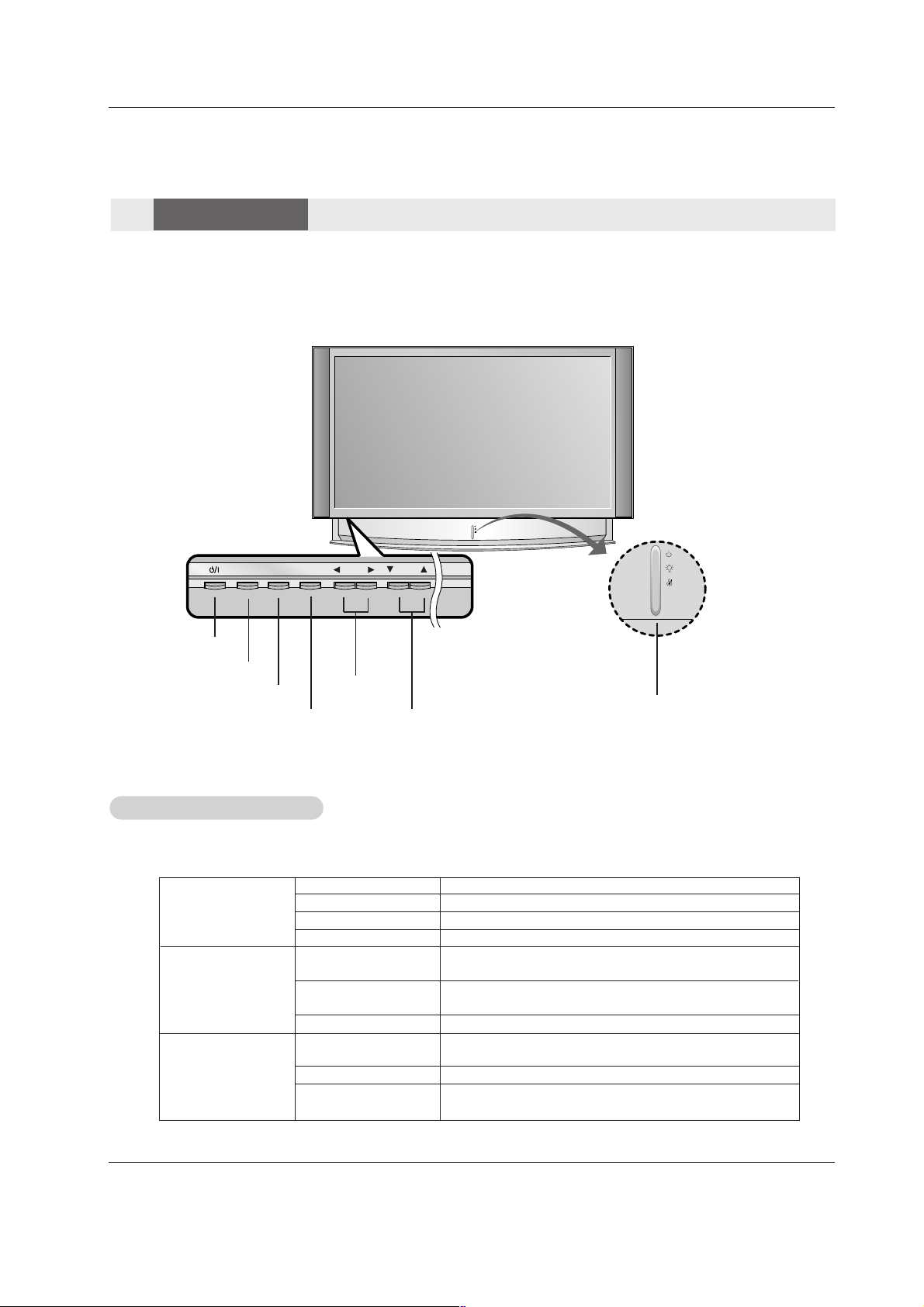
INPUT
VOL CH
ENTER
MENU
- Lamp indicator, operation indicator, and temperature indicator located below the front panel controls, reveal the
operating status of the DLP projection TV.
Function Status Indicators
Function Status Indicators
Controls
Controls
Front Panel Controls
Front Panel Controls
Off Power cord is not connected.
Red Power Cord is connected, TV is in standby mode.
Green TV turns on.
Orange (blinking) Preparing operation in standby mode.
Orange Projection lamp is reaching the end of its life and needs to
be replaced with a new lamp. Contact your service center.
Red (blinking) There is a problem with the lamp or around it. Contact an
authorized service center.
Green (blinking) The lamp cover is not closed.
Orange The projection TV is overheating. Check for blocked vents on
the projection TV.
Red The projection TV shut down due to overheating.
Red (blinking) The projection TV shut down, check the cooling fan. Contact
your service center.
Operation Indicator
Lamp Indicator
Temperature Indicator
- This is a simplified representation of a front panel.
- Image shown may be somewhat different from your TV.
POWER Button
MENU Button
ENTER Button
VOLUME (FF,GG)
Buttons
CHANNEL (EE, DD)
Buttons
Operation Indicator/
Lamp Indicator/
Temperature Indicator
INPUT Button
Owner’s Manual 7
Introduction
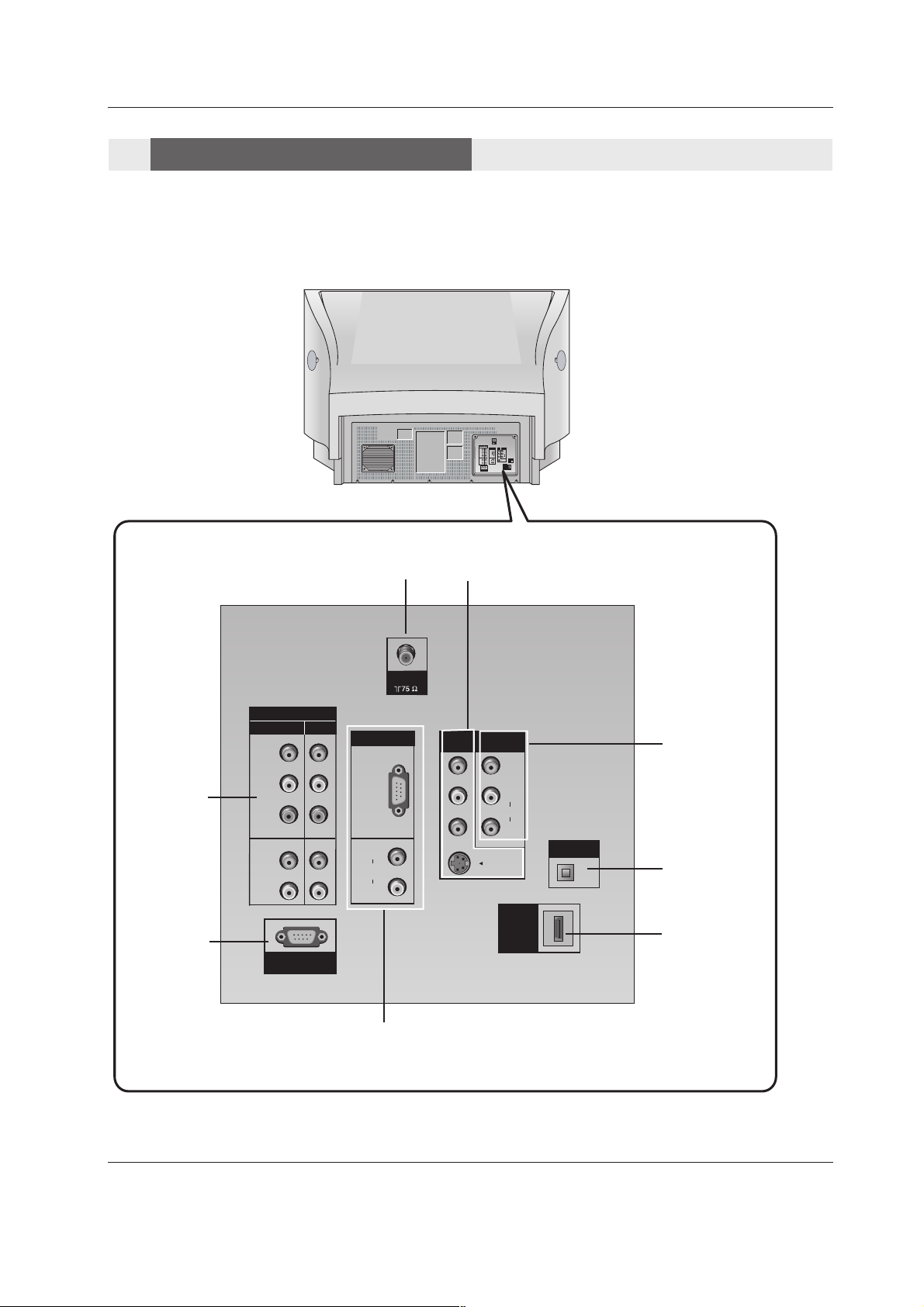
Back Connection Panel
Back Connection Panel
Connection Options
Connection Options
ANTENNA IN
COMPONENT
IN 1/2
SERVICE
ONLY
HDMI/DVI
IN
DIGITAL AUDIO
OPTICAL OUT
AV I N 1
AV OUT
RGB IN
RGB(PC/DTV)
RGB/DVI
ANTENNA
COMPONENT IN
2
1
RGB IN
AV IN 1
AV OUT
Y
VIDEO
RGB
VIDEO
PB
(PC/DTV)
(L)
AUDIO
MONO
PR
(R)
DIGITAL AUDIO
OPTICAL OUTPUT
(L)
(L)
S-VIDEO
AUDIO
RGBDVI
AUDIO
(R)
(R)
HDMI
/DVI IN
SERVICE ONLY
COMPONENT IN
2
Y
VIDEO
PB
PR
(L)
AUDIO
(R)
SERVICE ONLY
1
RGB IN
RGB
(PC/DTV)
(L)
AUDIO
RGBDVI
(R)
ANTENNA
AV IN 1
MONO
AV OUT
VIDEO
AUDIO
S-VIDEO
(L)
(R)
HDMI
/DVI IN
DIGITAL AUDIO
OPTICAL OUTPUT
8 DLP Projection TV
Introduction
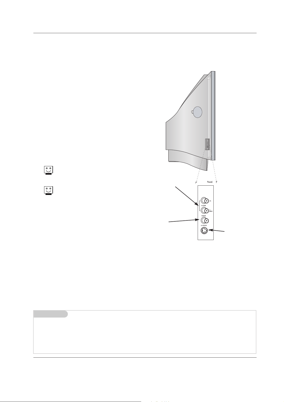
LEFT/RIGHT
AUDIO
Used for stereo
sound from various types of
equipment.
S-VIDEO
A connection
available on
some very highend equipment
that provides better picture quality
than video input.
VIDEO
Connects the
video signals
from any piece of
equipment.
AV IN 2 AV IN 2
AV IN 2
/
There are four jacks on the left side on your projection TV
that make connecting Audio/Video devices like video
games and camcorders very simple.
The jacks are like those found on the back jack connection
panel. This means that most equipment that connects to
those types of jacks on the rear jackpack, may be connected to the front connection panel.
To use the side jacks as the signal source, select them
using Main Input menu as described on page 23. They will
be named “Front Video” in the Main Input menu.
If you input both Front Video and
S-Video, only the S-Video will
work.
If you’re connecting a video game
device, make sure to change the
picture settings with the EZ
Picture option in the Video menu
(see page 24).
Mini glossary
A/V CABLESAudio/Video cables. Three cable connector—Right audio (red), Left audio (white), and Video (yellow). A/V cables are
used for stereo playback of videocassettes and for higher quality picture and sound from other A/V devices.
A/V DEVICE Any device that produces video or sound (VCR, DVD, cable box, or television).
Front Connection Panel
Front Connection Panel
Owner’s Manual 9
Introduction
1 2 3
4 5 6
7 8 9
0
TV
MODE
LIGHT
POWER
INPUT
INFO
HDMI/DVI
VCR
CABLE
DVD
SAT
MUTE
EZ PICSRS APM
EZ SOUND
RATIO
MENU EXIT
CC FREEZE
GUIDE
VOL
CH
FAV
SAP
ADJUST
TIMER
RGB PC/DTV
TV INPUT
FLASHBK
+
-
ENTER
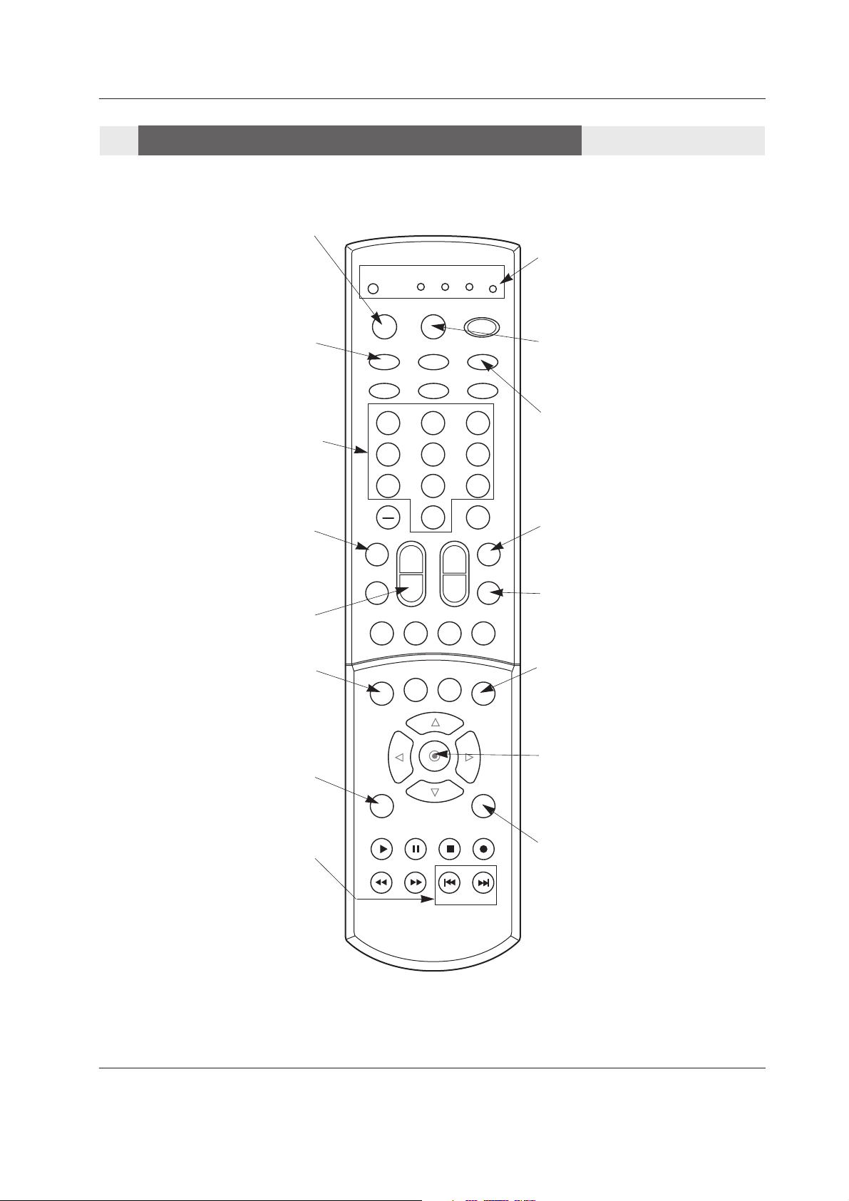
- When using the Remote Control, aim it at the remote control sensor on the TV.
Remote Control Key Functions
Remote Control Key Functions
INDICATOR LIGHTS
Show active remote mode
every time any button is
pressed.
MODE
Selects the remote operating mode:
TV, VCR, Cable, DVD and Satellite.
Select other operating modes, for the
remote to control external devices.
LIGHT
Illuminates the Remote
Control keys.
TV/VIDEO
Selects: Analog, Video1, Video2, Front
video, Component1-2, RGB, HDMI1/DVI
and HDMI2 input sources.
FAV
Scrolls the Favorite channels.
INFO
When you watch the TV, information displays on top of the screen. Not available
in Component 1-2, RGB, HDMI1/DVI and
HDMI2 mode.(Refer to p.36)
MUTE
Switches the sound on or off.
(Refer to
p.37)
ADJUST
Adjusts screen position, size, and phase
in RGB-DTV/PC mode.
VOLUME UP/DOWN
Increases/decreases the sound level.
NUMBER KEYPAD
For direct channel selection and
programming functions.
RATIO
Changes the screen format or aspect
ratio.
PIP INPUT
Selects the input source for the sub
picture.
ENTER
When in the menu system and other
on-screen displays, selects highlighted
options.
MENU
Brings up the main menu to the
screen.
EXIT
Clears all on-screen displays and returns
to TV viewing from any menu.
SKIP
Playing CDs: Selects songs.
Playing DVDs: Selects movie chapters.
10 DLP Projection TV
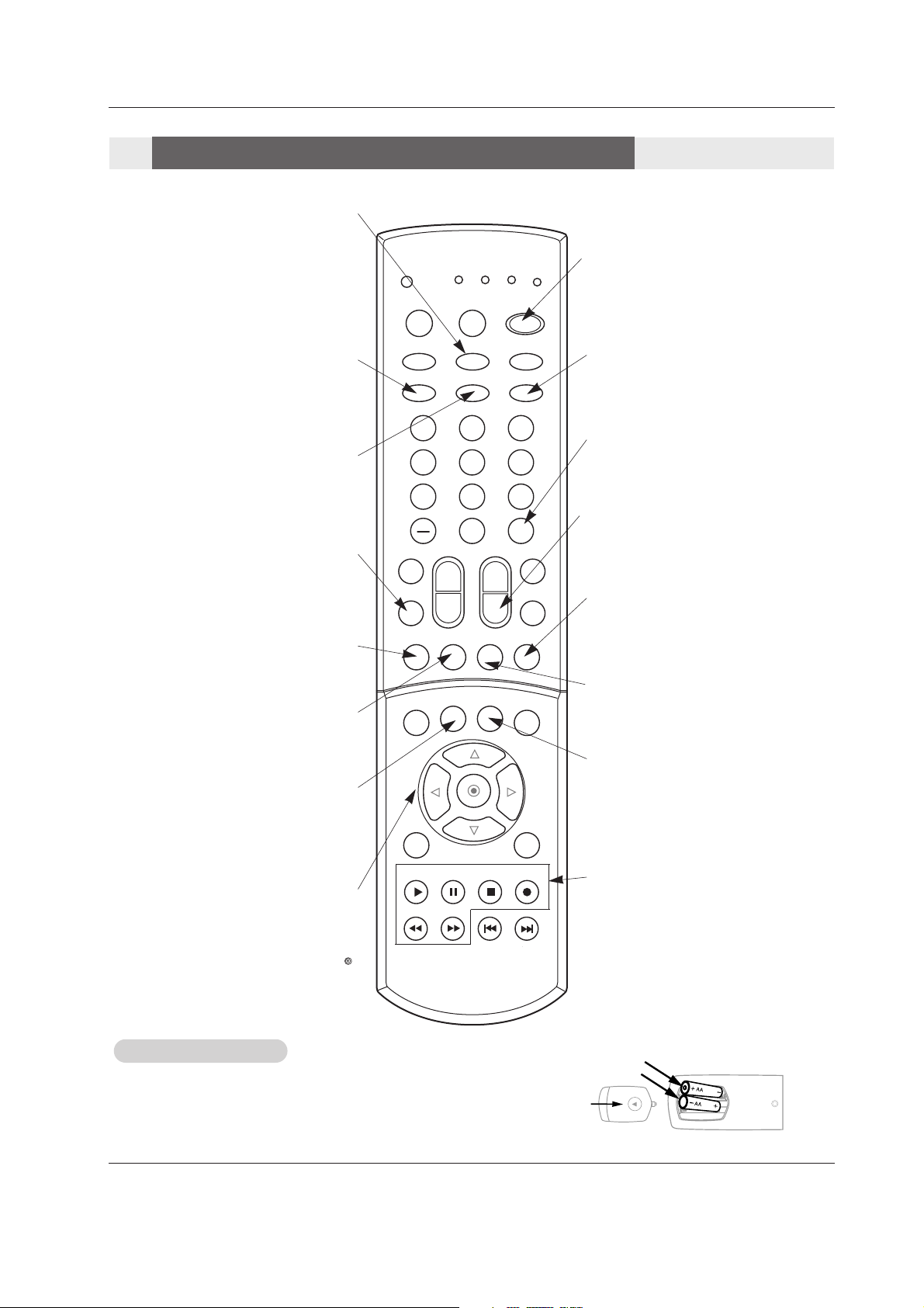
Introduction
• Open the battery compartment cover on the back side and install the batteries
matching correct polarity (+ with +, - with -).
• Install two 1.5V AA batteries. Don’t mix old or used batteries with new ones.
Close cover.
Installing Batteries
Installing Batteries
1 2 3
4 5 6
7 8 9
0
TV
MODE
LIGHT
POWER
INPUT
INFO
HDMI/DVI
VCR
CABLE
DVD
SAT
MUTE
EZ PICSRS APM
EZ SOUND
RATIO
MENU EXIT
CC FREEZE
GUIDE
VOL
CH
FAV
SAP
ADJUST
TIMER
RGB PC/DTV
TV INPUT
FLASHBK
+
-
ENTER
back of
remote
TV INPUT
• Rotates the input mode between Antenna
and Cable.
• Video 1-2, Front Video, Component 1-2,
RGB-DTV (or RGB-PC), HDMI1/DVI and
HDMI2
input sources, TV will return to the last TV
channel.
CC
Selects a closed caption mode for dis-
playing captioning information if avail-
able on program.
POWER
Turns your TV or any other programmed
equipment on or off, depending on mode.
EZ Sound
Selects the sound appropriate for
the program's character.
EZ Video
Adjusts the factory preset picture
depending on the viewing environ-
ment.
Remote Control Key Functions
Remote Control Key Functions
SLEEP
SAP
Selects MTS sound: Mono, Stereo, and
SAP in Analog mode. Change the audio
language in DTV mode.
CHANNEL UP/DOWN
Scrolls through available channels in
EZ Scan memory.
FLASHBK
Tunes to the last channel viewed.
PIPCH+
Changes to next higher PIP channel.
SWAP
Exchanges the main/sub images in
PIP/Twin picture mode.
PIPCH-
Changes to next lower PIP channel
PIP
Toggles between PIP and Twin picture
mode.
FREEZE
Freezes the currently-viewed picture.
Main picture is frozen in PIP/Twin picture
mode.
THUMBSTICK
Allows you to navigate the on-screen
menus and to adjust the system settings
and preferences, by moving to an option
with
F G
and selecting the highlighted
option with .
D
E
RECORD, PAUSE, REW, FFWD,
PLAY, STOP
Control the functions on your VCR.
Owner’s Manual 11
Installation
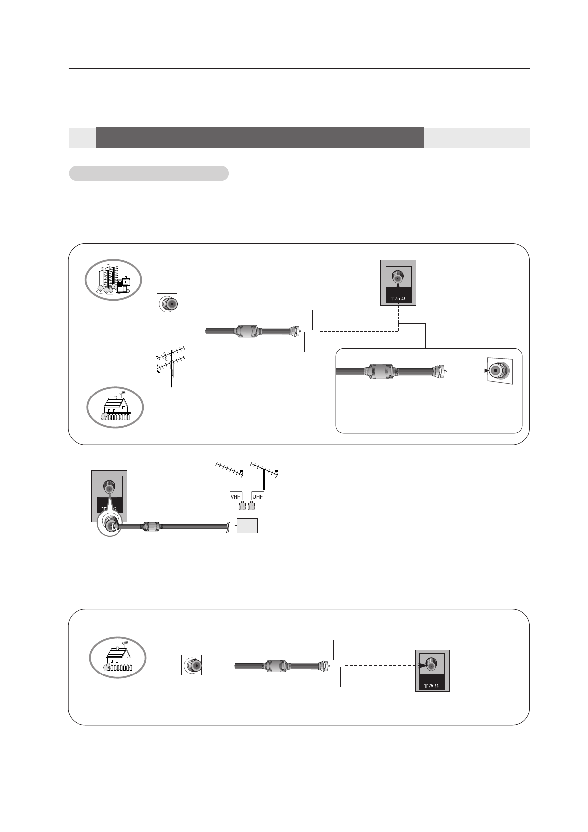
- Wall Antenna Socket or Outdoor Antenna without a Cable Box Connections
- For optimum picture quality, adjust antenna direction if needed.
Antenna or Cable Connection
Antenna or Cable Connection
1. Analog and Digital TV signals provided on one antenna
2. Analog and DTV signals provided on two separate antennas
Multi-family Dwellings/Apartments
(Connect to wall antenna socket)
Single-family Dwellings /Houses
(Connect to wall jack for outdoor antenna)
Outdoor
Antenna
Wall Antenna
Socket
VHF Antenna
UHF Antenna
RF Coaxial Wire (75 ohm)
Copper Wire
Turn clockwise to tighten.
Copper Wire
Be careful not to bend the Copper Wire when
connecting the antenna.
Copper Wire
Cable TV Wall
Jack
RF Coaxial Wire (75 ohm)
ANTENNA
Installation
Installation
External Equipment Connections
External Equipment Connections
Turn clockwise to tighten.
Note: The TV will let you know when the TV(analog antenna), DTV(digital antenna), CATV(analog cable) and CADTV(digital
cable) channel scans are complete.
• To improve the picture quality in a poor signal area,
please purchase a signal amplifier and install properly.
• If the antenna needs to be split for two TV’s, install a “2Way Signal Splitter” in the connections.
• If the antenna is not installed properly, contact your dealer for assistance.
ANTENNA
ANTENNA
Signal
Amplifier
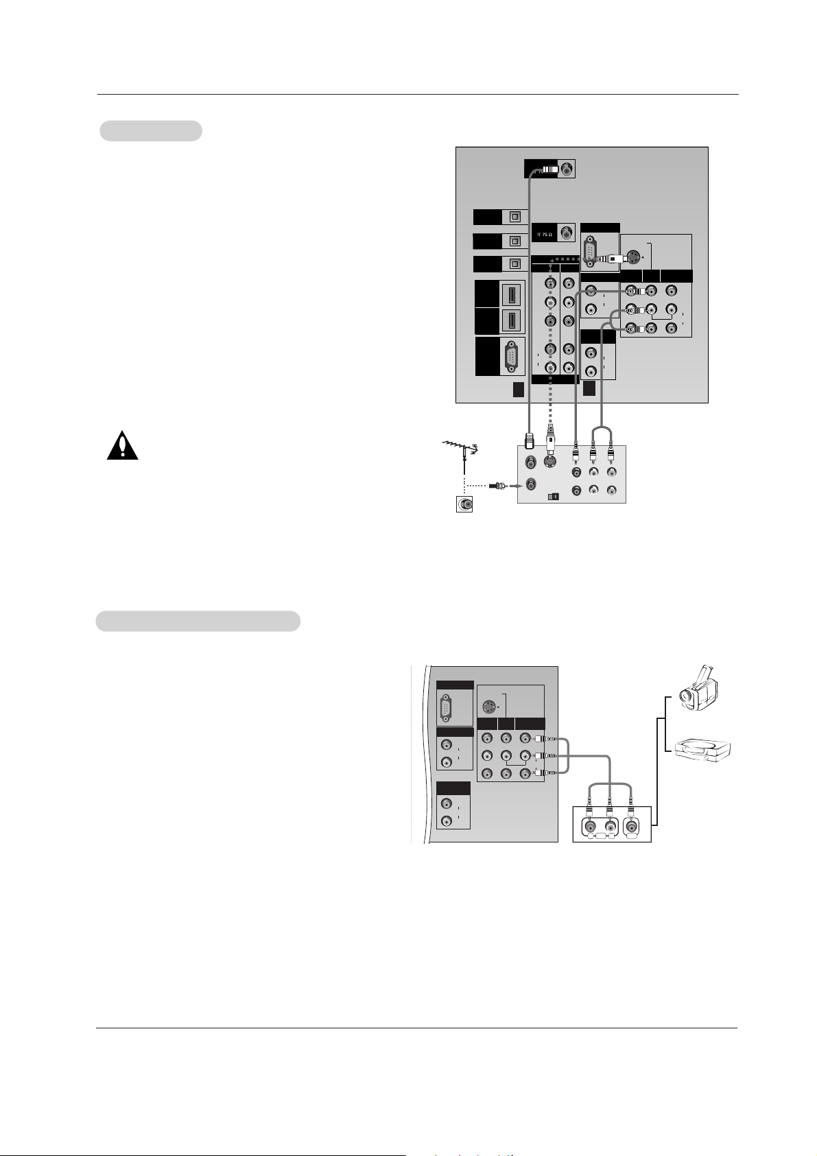
How to connect
Connect the audio and video cables from the external equipment's output jacks to the TV input jacks, as shown in the
figure.
When connecting the TV to external equipment, match the
jack colors (Video = yellow, Audio Left = white, and Audio
Right = red).
How to use
1. Select the input source by using the TV/VIDEO button on
the Remote Control. Note that this TV finds the connected
input sources automatically for Video 1-2 and Component 1-
2. It is presumed that RGB, HDMI1/DVI and HDMI2 sources
are connected.
2. Operate the corresponding external equipment.
External
External
A/V Source Setup
A/V Source Setup
S-VIDEO
MONO
RGB INPUT
RGB/DVI INPUT
(L)
(R)
AUDIO
(L)
(R)
AUDIO
VIDEO
(L)
(R)
AUDIO
MONITOR
OUT
INPUT2
INPUT1
VARIABLE
AUDIO OUT
(L)
(R)
VIDEO
RL
AUDIO VIDEO
PC/DTV
(XGA/
480p/
720p/
1080i)
Camcorder
Video Game
Set
12 DLP Projection TV
Connection Option 1
Set VCR output switch to channel 3 or 4 and then tune the
TV to the same channel number.
Connection Option 2
1. Connect the audio and video cables from the VCR's output
jacks to the TV input jacks, as shown in the figure.
When connecting the TV to VCR, match the jack colors
(Video = yellow, Audio Left = white, and Audio Right = red).
If you connect an S-VIDEO output from VCR to the S-VIDEO
input, the picture quality is improved; compared to connecting
only the Video input.
2. Insert a video tape into the VCR and press PLAY on the
VCR. (Refer to the VCR owner’s manual.)
3. Select the input source with using the TV/VIDEO button on
the remote control. Note that this TV finds the connected
input sources automatically for Video1-2, Front Video and
Component 1-2. It is presumed that RGB, HDMI1/DVI and
HDMI2 sources are connected.
Do not connect to both Video1,2 and S-Video at the
same time. In the event that you connect both Video
and the S-Video cables, only the S-Video will work.
VCR Setup
VCR Setup
S-VIDEO
PR
PB
Y
MONO
RGB INPUT
COMPONENT
INPUT2
INPUT1
DTV/DVD INPUT
RGB/DVI INPUT
(L)
(R)
AUDIO
(L)
(R)
AUDIO
VIDEO
(L)
(R)
AUDIO
MONITOR
OUT
INPUT2
INPUT1
DIGITAL AUDIO
OPTICAL INPUT
(COMPONENT2)
DIGITAL AUDIO
OPTICAL INPUT
(DVI)
DIGITAL AUDIO
OPTICAL OUTPUT
ANTENNA
H
D
M
I
1
VARIABLE
AUDIO OUT
UPGRADE
PORT
CABLE
/
D
V
I
H
D
M
I
2
S-VIDEO
OUT
IN
(R) AUDIO (L)VIDEO
34
OUTPUT
SWITCH
ANT OUT
ANT IN
PC/DTV
(XGA/
480p/
720p/
1080i)
(L)
(R)
AUDIO
VCR Rear
1
2
Installation

Owner’s Manual 13
Installation
• Component Input ports
To get better picture quality, connect a DVD player to the
component input ports as shown below.
Component ports
on the TV
Y PB
P
R
Video output ports
on DVD player
Y
Y
Y
Y
Pb
B-Y
Cb
PB
Pr
R-Y
Cr
PR
How to connect
1. Connect the DVD video outputs (Y, P
B
, PR) to the COMPO-
NENT (Y, P
B, PR) INPUT jacks on the TV and connect the
DVD audio outputs to the AUDIO INPUT jacks on the TV, as
shown in the figure.
2. If your DVD only has an S-Video output jack, connect this to
the S-VIDEO input on the TV and connect the DVD audio outputs to the AUDIO INPUT jacks on the TV, as shown in the figure.
Note: If your DVD player does not have component video output,
use S-Video.
How to use
1. Turn on the DVD player, insert a DVD.
2. Use the TV/VIDEO button on the Remote Control to select
Component 1 or Component 2. (If connected to S-VIDEO,
select the Video2 or Front Video external input source.)
3. Refer to the DVD player's manual for operating instructions.
DVD Setup
DVD Setup
S-VIDEO
PR
PB
Y
MONO
RGB INPUT
COMPONENT
INPUT2
INPUT1
DTV/DVD INPUT
RGB/DVI INPUT
(L)
(R)
AUDIO
(L)
(R)
AUDIO
VIDEO
(L)
(R)
AUDIO
(L)
(R)
AUDIO
MONITOR
OUT
INPUT2
INPUT1
DIGITAL AUDIO
OPTICAL INPUT
(COMPONENT2)
DIGITAL AUDIO
OPTICAL INPUT
(DVI)
DIGITAL AUDIO
OPTICAL OUTPUT
ANTENNA
H
D
M
I
1
VARIABLE
AUDIO OUT
UPGRADE
PORT
CABLE
/
D
V
I
H
D
M
I
2
(R) AUDIO (L)
S-VIDEO
B
R
(R) AUDIO (L)
DIGITAL AUDIO
OPTICAL
PC/DTV
(XGA/
480p/
720p/
1080i)
DVD
Notes:
• Digital Audio will not work for Component 1 input source.
• Digital Audio operation has priority if Digital Audio and AUDIO L/R
are connected at the same time.
or
How to connect
Use the TV’s COMPONENT (Y, P
B, PR) INPUT, RGB, HDMI1/DVI or
HDMI2 jack for video connections, depending on your set-top box connector. Then, make the corresponding audio connections.
Note: HDMI(High Definition Multimedia Interface): Input that accepts uncom-
pressed digital signal and multi channel digital audio signal.
How to use
1. Turn on the digital set-top box. (Refer to the owner’s manual for the digital
set-top box.)
2. Use TV/VIDEO on the Remote Control to select Component 1,
Component 2, RGB-DTV, HDMI1/DVI or HDMI2 source.
HDSTB Setup
HDSTB Setup
- This TV can receive Digital Over-the-air/Cable signals without an external digital set-top box. However, if you do receive Digital
signals from a digital set-top box or other digital external device, refer to the figure as shown below.
- This TV supports HDCP (High-bandwidth Digital Contents Protection) protocol for Digital Contents (480p,720p,1080i).
Signal
480i
480p
720p
1080i
Component 1/2
Yes
Yes
Yes
Yes
RGB-DTV,HDMI1/DVI,HDMI2
No
Yes
Yes
Yes
14 DLP Projection TV
PC Setup
PC Setup
- This TV provides Plug and Play capability, meaning that the PC adjusts automatically to the TV's settings.
- The TV perceives 640x480, 60Hz as DTV 480p based on the PC graphic card, change the screen scanning rate for the graphic
card accordingly.
Resolution
800x600
Horizontal
Frequency(KHz)
70.09
59.94
72.80
75.00
48.363
56.476
60.023
Vertical
Frequency(Hz)
1024x768
Monitor Display Specifications (RGB-PC or HDMI1/DVI Mode)
35.156
37.879
48.077
46.875
56.25
60.31
72.18
75.00
60.00
70.06
75.02
Installation
The TV has a special signal output capability which allows you to
hook up a second TV or monitor.
Connect the second TV or monitor to the TV’s MONITOR OUTPUT.
See the Operating Manual of the second TV or monitor for further
details regarding that device’s input settings.
Note
• Component, RGB-PC/RGB-DTV, HDMI1/DVI,HDMI2, DTV input
sources cannot be used for Monitor out.
Monitor Out Setup
Monitor Out Setup
S-VIDEO
IN
(R) AUDIO (L) VIDEO
S-VIDEO
MONO
RGB INPUT
RGB/DVI INPUT
(L)
(R)
AUDIO
(L)
(R)
AUDIO
MONITOR
OUT
INPUT2
INPUT1
VARIABLE
AUDIO OUT
PC/DTV
(XGA/
480p/
720p/
1080i)
31.468
31.469
37.861
37.500
640x350
640x480
RGB-PC
Mode Only
Owner’s Manual 15
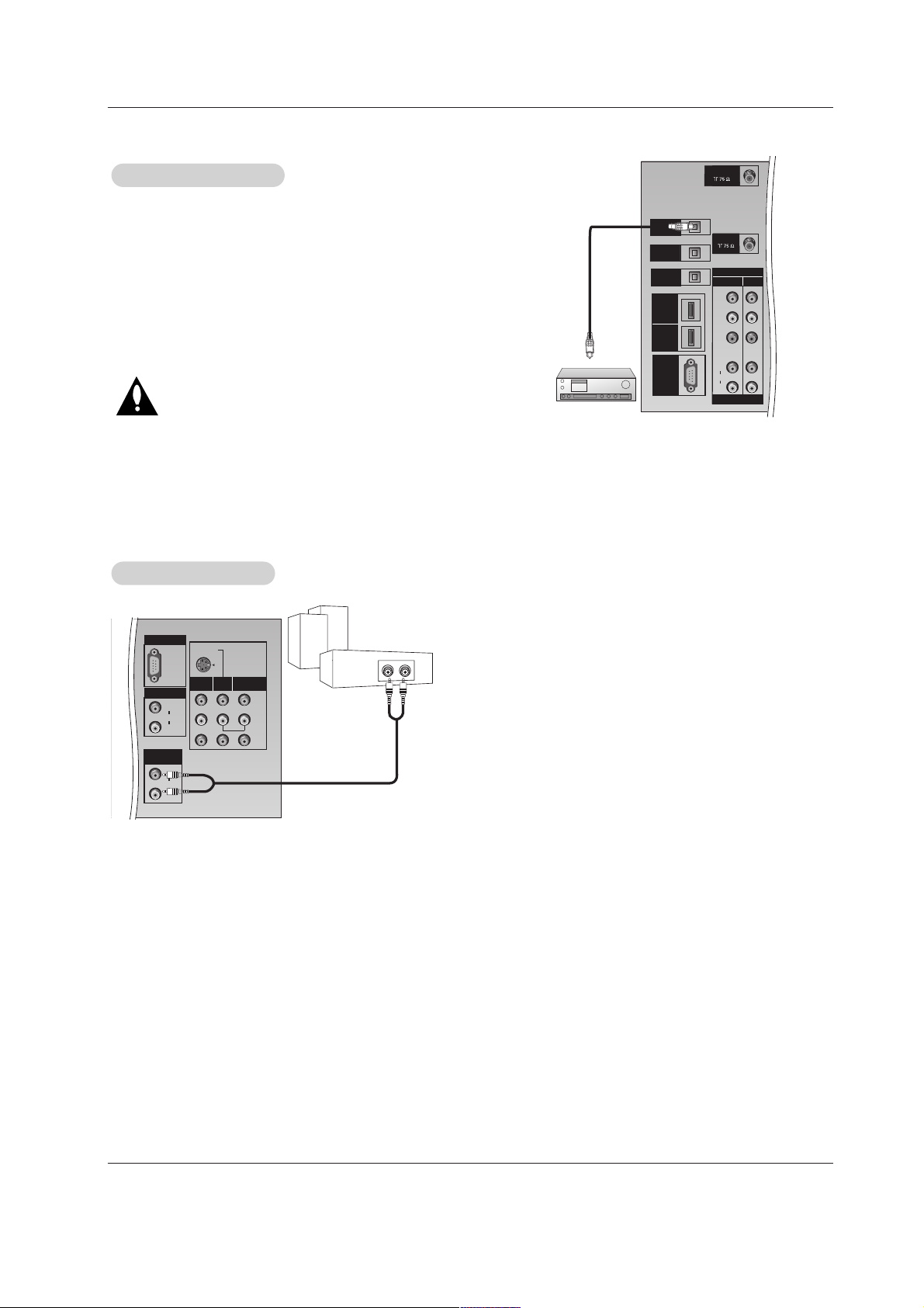
Installation
Send the TV’s audio to external audio equipment (stereo system) via
the Digital Audio Output (Optical) port.
How to connect
1. Connect one end of an optical cable to the TV Digital Audio
(Optical) Output port.
2. Connect the other end of the optical cable to the digital audio (optical) input on the audio equipment.
3. Set the “ TV Speaker option - Off” in the AUDIO menu. Refer to
page 26.
See the external audio equipment instruction manual for operation.
Caution: Do not look into the optical output port. Looking
at the light may damage your vision.
Digital
Digital
Audio Output
Audio Output
Hook up Variable Audio Output, L-Audio-R to Amplifier system for
Left/Right front speaker sound.
How to connect
1. Locate the Variable Audio Out jacks on the back of your TV and the
Input jacks on the back of your stereo's amplifier.
2. Connect the two jacks, making sure that the right and left channels
are connected correctly.
3. Set up your speakers through your analog stereo amplifier, according to the instructions provided with the amplifier.
External Stereo
External Stereo
S-VIDEO
MONO
RGB INPUT
RGB/DVI INPUT
(L)
(R)
AUDIO
(L)
(R)
AUDIO
MONITOR
OUT
INPUT2
INPUT1
VARIABLE
AUDIO OUT
PC/DTV
(XGA/
480p/
720p/
1080i)
ANTENNA
C
A
B
L
E
C
A
R
D
DVI
HDMI
DIGITAL AUDIO
OPTICAL OUTPUT
DIGITAL AUDIO
OPTICAL INPUT
(COMPONENT2)
DIGITAL AUDIO
OPTICAL INPUT
(DVI)
H
/
D
D
M
V
I
I
1
H
D
M
I
2
UPGRADE
PORT
CABLE
COMPONENT
INPUT2
Y
PB
PR
(L)
AUDIO
(R)
DTV/DVD INPUT
INPUT1
 Loading...