

LG 55LE5300, 26LE5300, 37LE5300, 22LE6500, 42LE5300 Owner's Manual
...
P/NO : MFL59166625 (1008-REV03)
www.lg.com
OWNER’S MANUAL
LED LCD TV / LCD TV /
PLASMA TV
Please read this manual carefully before operating
your set and retain it for future reference.
22LE6500
26LE6500
32LE4600
42LE4600
47LE4600
55LE4600
32LD465
37LD465
42LD465
47LD465
32LD420
42LD420
LED LCD TV MODELS
22LE5300
26LE5300
32LE5300
37LE5300
42LE5300
47LE5300
55LE5300
LCD TV MODELS
32LD350
32LD460
37LD460
42LD460
47LD460
37LD461C
42LD461C
PLASMA TV MODELS
42PJ230
50PJ230
42PJ250
50PJ250
42PJ350
50PJ350
32LD420C
42LD420C
WARNING / CAUTION
TO REDUCE THE RISK OF ELECTRIC
SHOCK DO NOT REMOVE COVER (OR
BACK). NO USER SERVICEABLE PARTS
INSIDE. REFER TO QUALIFIED SERVICE
PERSONNEL.
The lightning flash with arrowhead
symbol, within an equilateral triangle, is intended to alert the user to
the presence of uninsulated “dangerous voltage” within the product’s enclosure that may be of sufficient magnitude to
constitute a risk of electric shock to persons.
The exclamation point within an equi-
lateral triangle is intended to alert
the user to the presence of important operating and maintenance (servicing) instructions in the literature accompanying the
appliance.
2
SAFETY INSTRUCTIONS
IMPORTANT SAFETY INSTRUCTIONS
Read these instructions.
Keep these instructions.
Heed all warnings.
Follow all instructions.
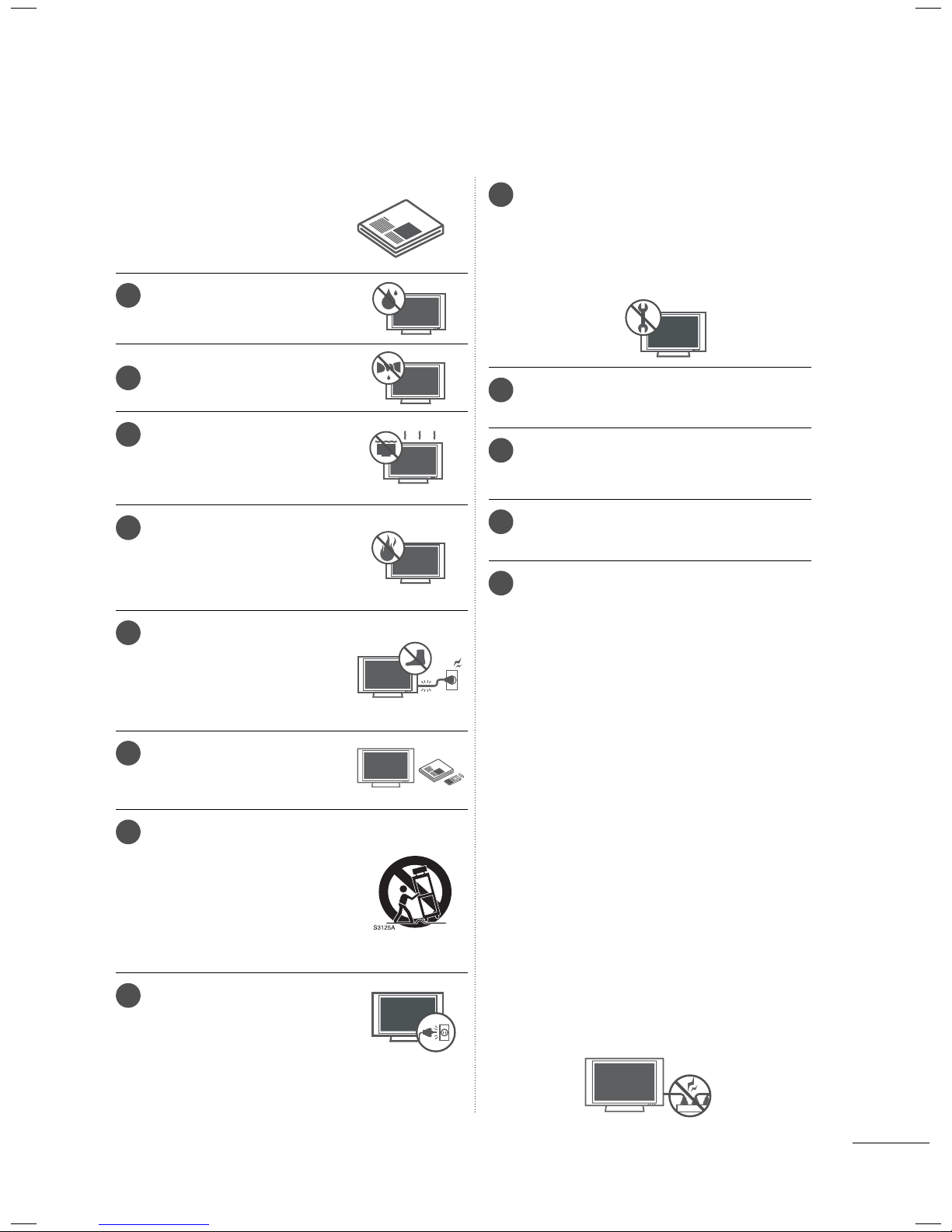
1
Do not use this apparatus
near water.
Clean only with dry cloth.
2
Do not block any ventilation
3
openings. Install in accordance
with the manufacturer’s
instructions.
Do not install near any heat
4
sources such as radiators, heat
registers, stoves, or other apparatus (including amplifiers) that
produce heat.
Protect the power cord from
5
being walked on or pinched
particularly at plugs, convenience receptacles, and the
point where they exit from the
apparatus.
Only use attachments/acces-
6
sories specified by the manufacturer.
7
Use only with the cart, stand,
tripod, bracket, or table specified by the manufacturer, or
sold with the apparatus. When
a cart is used, use caution
when moving the cart/apparatus combination to avoid injury
from tip-over.
8
Unplug this apparatus during
lighting storms or when unused
for long periods of time.
Refer all servicing to qualified service personnel. Servicing is required when the appa-
9
ratus has been damaged in any way, such
as power-supply cord or plug is damaged,
liquid has been spilled or objects have fallen
into the apparatus, the apparatus has been
exposed to rain or moisture, does not operate normally, or has been dropped.
Never touch this apparatus or antenna dur-
10
ing a thunder or lighting storm.
When mounting a TV on the wall, make sure
11
not to install the TV by the hanging power
and signal cables on the back of the TV.
Do not allow an impact shock or any objects
12
to fall into the product, and do not drop
onto the screen with something.
CAUTION concerning the Power Cord:
13
It is recommend that appliances be placed
upon a dedicated circuit; that is, a single
outlet circuit which powers only that appliance and has no additional outlets or
branch circuits. Check the specification
page of this owner's manual to be certain.
Do not connect too many appliances to the
same AC power outlet as this could result in
fire or electric shock.
Do not overload wall outlets. Overloaded
wall outlets, loose or damaged wall outlets,
extension cords, frayed power cords, or
damaged or cracked wire insulation are
dangerous . Any of these conditions could
result in electric shock or fire. Periodically
examine the cord of your appliance, and if its
appearance indicates damage or deterioration, unplug it, discontinue use of the appliance, and have the cord replaced with an
exact replacement part by an authorized
servicer. Protect the power cord from physical or mechanical abuse, such as being
twisted, kinked, pinched, closed in a door, or
walked upon. Pay particular attention to
plugs, wall outlets, and the point where the
cord exits the appliance.
Do not make the TV with the power cord
plugged in. Do not use a damaged or loose
power cord. Be sure do grasp the plug
when unplugging the power cord. Do not
pull on the power cord to unplug the TV.
3
SAFETY INSTRUCTIONS
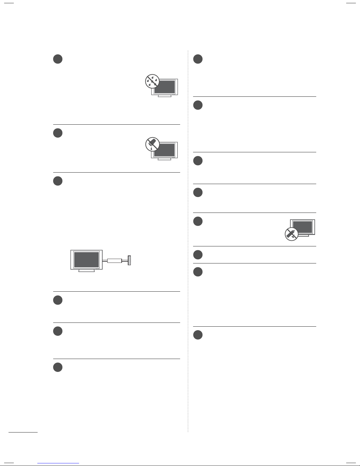
WARNING - To reduce the risk
14
of fire or electrical shock, do not
expose this product to rain,
moisture or other liquids. Do
not touch the TV with wet
hands. Do not install this product near flammable objects
such as gasoline or candles or
expose the TV to direct air
conditioning.
Do not expose to dripping or
15
splashing and do not place
objects filled with liquids, such
as vases, cups, etc. on or over
the apparatus (e.g. on shelves
above the unit).
GROUNDING
16
Ensure that you connect the earth ground wire
to prevent possible electric shock (i.e. a TV with
a three-prong grounded AC plug must be connected to a three-prong grounded AC outlet). If
grounding methods are not possible, have a
qualified electrician install a separate circuit
breaker.
Do not try to ground the unit by connecting it to
telephone wires, lightening rods, or gas pipes.
Moving
20
Make sure the product is turned off,
unplugged and all cables have been
removed. It may take 2 or more people to
carry larger TVs. Do not press against or put
stress on the front panel of the TV.
Ventilation
21
Install your TV where there is proper ventilation. Do not install in a confined space such
as a bookcase. Do not cover the product
with cloth or other materials (e.g.) plastic
while plugged in. Do not install in excessively dusty places.
Take care not to touch the ventilation open-
22
ings. When watching the TV for a long
period, the ventilation openings may
become hot.
If you smell smoke or other odors coming
23
from the TV, unplug the power cord and contact and authorized service center.
Do not press strongly upon the
24
panel with hand or sharp object
such as nail, pencil or pen, or
make a scratch on it.
Power
Supply
Short-circuit
Breaker
DISCONNECTING DEVICE FROM MAINS
17
Mains plug is the disconnecting device. The
plug must remain readily operable.
As long as this unit is connected to the AC
18
wall outlet, it is not disconnected from the AC
power source even if you turn off this unit by
SWITCH.
Cleaning
19
When cleaning, unplug the power cord and
scrub gently with a soft cloth to prevent
scratching. Do not spray water or other liquids
directly on the TV as electric shock may
occur. Do not clean with chemicals such as
alcohol, thinners or benzene.
Keep the product away from direct sunlight.
25
Dot Defect
26
The Plasma or LCD panel is a high technology product with resolution of two million to
six million pixels. In a very few cases, you
could see fine dots on the screen while
you’reviewing the TV. Those dots are deactivated pixels and do not affect the performance and reliability of the TV.
Generated Sound
27
“Cracking” noise: A cracking noise that occurs
when watching or turning off the TV is generated by plastic thermal contraction due to
temperature and humidity. This noise is common for products where thermal deformation
is required.
Electrical circuit humming/panel buzzing: A
low level noise is generated from a high-speed
switching circuit, which supplies a large amount
of current to operate a product. It varies
depending on the product.
This generated sound does not affect the performance and reliability of the product.
4

For LED LCD TV/LCD TV
28
If the TV feels cold to the touch, there may be
a small “flicker” when it is turned on. This is
normal, there is nothing wrong with TV.
Some minute dot defects may be visible on
the screen, appearing as tiny red, green, or
blue spots. However, they have no adverse
effect on the monitor’s performance.
Avoid touching the LCD screen or holding your
finger(s) against it for long periods of time.
Doing so may produce some temporary distortion effects on the screen.
ON DISPOSAL
(Only Hg lamp used LCD TV)
The fluorescent lamp used in this product contains a small amount of mercury. Do not
dispose of this product with general household waste. Disposal of this product must be
carried out in accordance to the regulations of
your local authority.
5

CONTENTS
WARNING / CAUTION
SAFETY INSTRUCTIONS
FEATURE OF THIS TV
..............................2
........................3
............................. 8
PREPARATION
Accessories .............................................................9
Front Panel Information ....................................12
Back Panel Information .....................................18
Stand Instructions
Woofer Installation: When Using The Wall
...............................................................................30
Mount
VESA Wall Mounting .........................................31
Cable Management .......................................... 33
Desktop Pedestal Installation ......................... 37
Swivel Stand ........................................................ 37
Attaching the TV to a Desk
Kensington Security System ..........................38
Securing the TV to the wall to prevent falling
when the tv is used on a stand ..................... 39
Antenna or Cable Connection .......................40
.....................................................23
......................... 38
EXTERNAL EQUIPMENT SETUP
HD Receiver Setup .............................................41
DVD SETUP .........................................................44
VCR SETUP .........................................................46
Other A/V Source Setup ................................. 47
USB Connection ................................................48
Headphone Setup .............................................48
Audio Out Connection .....................................49
External Equipment WIreless Connection .50
PC Setup ...............................................................51
WATCHING TV / CHANNEL CONTROL
Remote Control Functions ..............................58
Turning on the TV ..............................................60
Channel Selection..............................................60
Volume Adjustment ..........................................60
Initial Setting ........................................................ 61
On-Screen Menus Selection ..........................63
Quick Menu .........................................................65
Customer Support
- Software Update .............................................66
- Picture Test/Sound Test ................................ 67
- Product/Service Info. .....................................68
Simple Manual .................................................... 69
Channel Setup
- Auto Scan (Auto Tuning) .............................. 70
- Add/Delete Channel (Manual Tuning) ......71
Channel Editing .................................................. 72
Favorite Channel Setup .................................... 73
Favorite Channel List ........................................ 73
Channel List ........................................................ 74
Scan Option ........................................................ 75
System Color ....................................................... 76
Channel Brief Information ............................... 77
EPG (Electronics Program Guide) ................ 79
Input List ..............................................................82
Input Label ...........................................................83
Mode Setting ......................................................84
Demo Mode ........................................................85
Initial Setting (Reset to Factory Default) .....86
AV Mode ............................................................... 87
SIMPLINK .............................................................88
MY MEDIA
Connection Method ..........................................90
Entry Mode ...........................................................91
Movie list ...............................................................92
Photo list ...............................................................99
Music list ............................................................. 105
DivX Registration Code ...................................110
Deactivation ..........................................................111
PICTURE CONTROL
Picture Size (Aspect Ratio) Control ............. 112
Picture Wizard .................................................... 114
ꕊ Energy Saving ............................................. 116
Preset Picture Settings (Picture Mode) .......117
Manual Picture Adjustment - User Mode . 118
Picture Impro
Control) ................................................................ 119
Expert Picture Control .................................... 120
Picture Reset ..................................................... 123
TruMotion ........................................................... 124
Power Indicator ................................................. 125
Image Sticking Minimization (ISM) Method
vement Technology (Advanced
.126
6

SOUND & LANGUAGE CONTROL
APPENDIX
Auto Volume .......................................................127
Balance ................................................................127
Clear Voice II ..................................................... 128
Preset Sound Settings (Sound Mode) ...... 129
Sound Setting Adjustment - User Mode . 130
Audio Reset ........................................................ 131
Digital Audio Out .............................................. 131
TV Speakers On/Off Setup .......................... 132
Stereo/SAP Broadcast Setup ...................... 133
Audio Language ............................................. 134
On-screen Menus Language Selection .... 135
Caption Mode
- Analog Broadcasting System Captions . 136
- Digital Broadcasting System Captions ....137
TIME SETTING
Clock Setting
- Auto Clock Setup ......................................... 138
- Manual Clock Setup .................................... 139
Auto On/Off Time Setting ............................140
Sleep Timer Setting ......................................... 141
Troubleshooting ................................................ 149
Maintenance ...................................................... 152
Product Specifications ................................... 153
IR Codes ............................................................. 158
External Control through RS-232C ........... 159
Open Source Software Notice ..................... 165
PARENTAL CONTROL / RATINGS
Set Password & lock system-
- Setting up Your Password .......................... 142
- Set Password ................................................. 143
- Lock System ...................................................144
Channel Blocking ............................................. 145
Movie Rating ..................................................... 146
External Input Blocking ...................................147
Key Lock ............................................................. 148
7
FEATURE OF THIS TV
ꔛ
Some of these features are not available on all models.
Manufactured under license from
Dolby Laboratories. “Dolby “and the
double-D symbol are trademarks of
Dolby Laboratories.
HDMI, the HDMI logo and HighDefinition Multimedia Interface are
trademarks or registered trademarks of HDMI Licensing LLC."
ABOUT DIVX VIDEO: DivX® is a digital
video format created by DivX,Inc. This is
an official DivX Certified device that
plays DivX video. Visit www.divx.com for
more information and software tools to
convert your files into DivX video.
ABOUT DIVX VIDEO-ON-DEMAND:
This DivX Certified® device must be
registered in order to play DivX Videoon-Demand (VOD) content. To generate the registration code, locate the
DivX VOD section in the device setup
menu. Go to vod.divx.com with this
code to complete the registration process and learn more about DivX VOD.
“DivX Certified to play DivX video up to
HD 1080p, including premium content”
“Pat. 7,295,673; 7,460,668; 7,515,710;
7,519, 274”
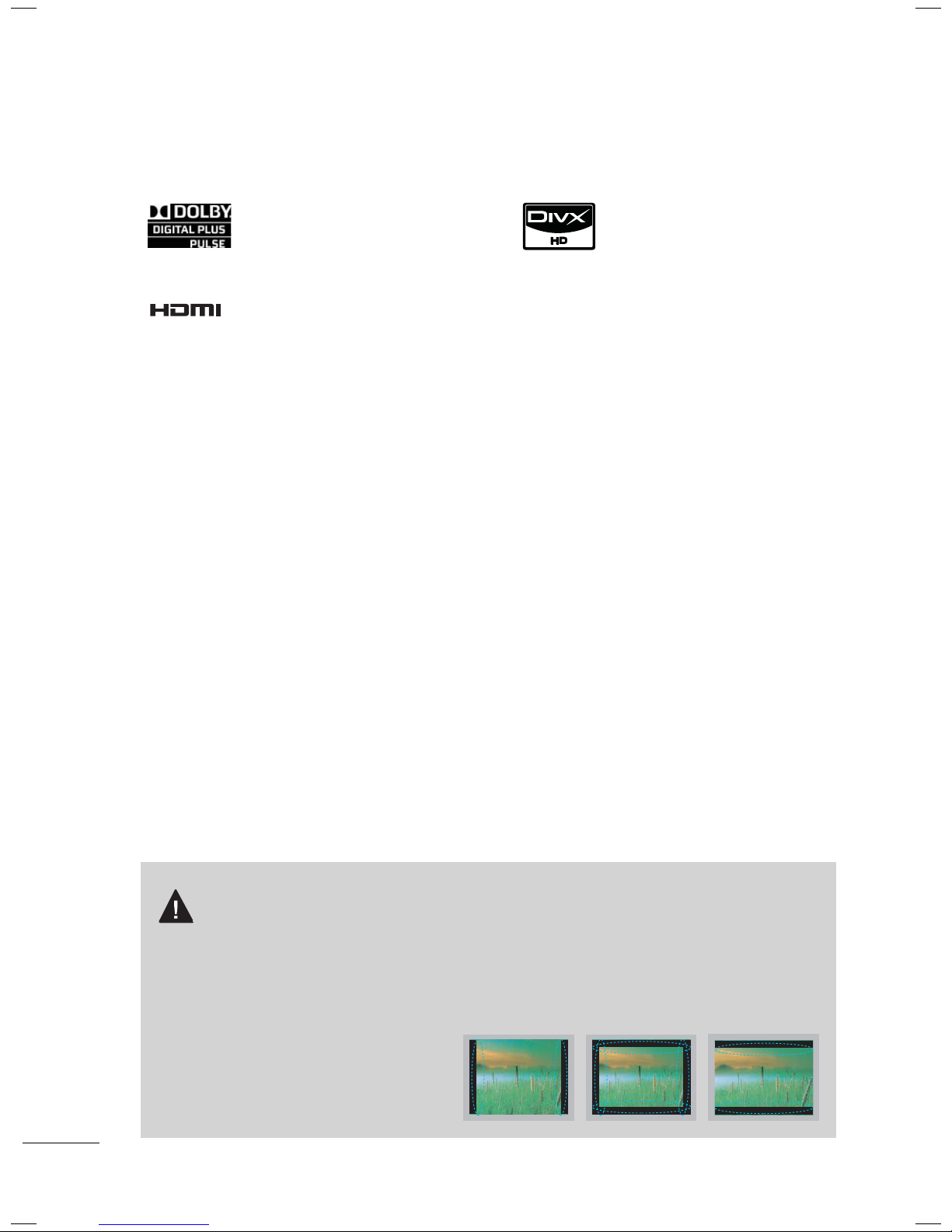
IMPORTANT INFORMATION TO PREVENT “IMAGE
BURN / BURN-IN” ON YOUR TV SCREEN
ꔛ
When a fixed image (e.g. logos, screen menus, video game, and computer display) is displayed
on the TV for an extended period, it can become permanently imprinted on the screen. This
phenomenon is known as “image burn” or “burn-in.” Image burn is not covered under the manufacturer’s warranty.
ꔛ
In order to prevent image burn, avoid displaying a fixed image on your TV screen for a prolonged
period (2 or more hours for LCD, 1 or more
hours for Plasma).
ꔛ
Image burn can also occur on the letterboxed areas of your TV if you use the 4:3
aspect ratio setting for an extended period.
8
PREPARATION
1.5V 1.5V
ENERGY
CHVOL
12
3
456
78
0
9
SAVING
TV
AV MODE
INPUT
FAV
RATIO
MUTE
MARK
Q.VIEW
LIST
FREEZE
P
A
G
E
ENTER
MENU
GUIDE
Q.MENU
INFO
BACK
EXIT
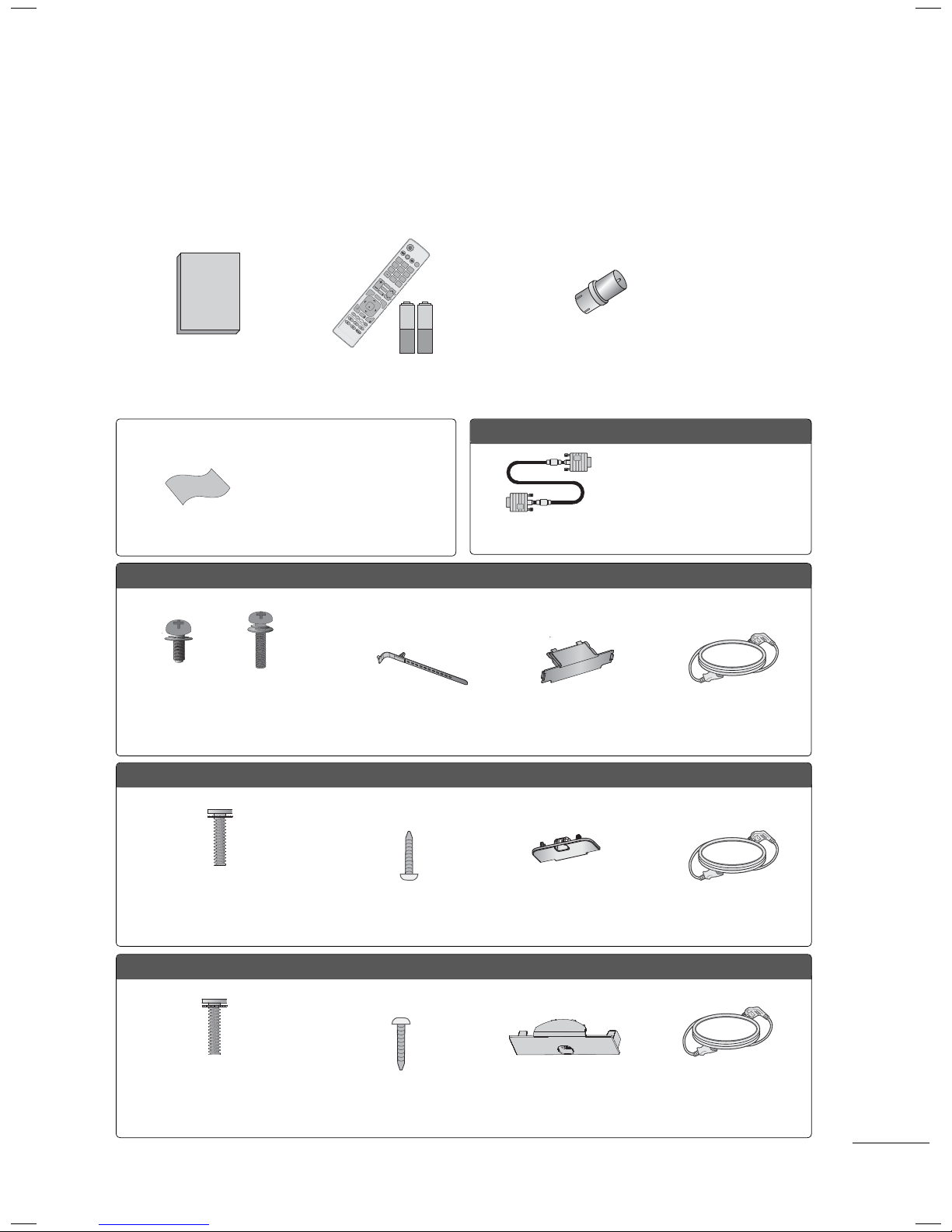
ACCESSORIES
Ensure that the following accessories are included with your TV. If an accessory is missing, please contact the dealer where you purchased the TV.
The accessories included may differ from the images below.
RF Adapter (Some models)
You must connect it to the
Owner’s Manual
Remote Control,
Batteries (AAA)
antenna wire after fixing in
Antenna Input. This adapter is
for supplied in Argentina.
Not included with all models
Option Extras
* Wipe spots on the exterior only
with the polishing cloth.
* Do not wipe roughly when remov-
Polishing Cloth
ing stain. Excessive pressure may
cause scratch or discoloration.
D-sub 15 pin Cable
Plasma TV
x 3
x 4
x 2
(M5 x 14)
Screws for stand assembly
(Refer to P.23)
(M4 x 28)
Cable Holder
(Refer to P.33)
Protection Cover
32LD350, 32/37/42/47LD460, 37/42LD461C, 32/37/42/47LD465
(Except 47LD460,
47LD465)
x 8
(M4 x 20)
Screws for stand assembly
(Refer to P.24)
Screw for stand fixing
(Refer to P.38)
Protection Cover
(Refer to P.24)
When using the VGA (D-sub 15
pin cable) PC connection, the
user must use shielded signal
interface cables with ferrite cores
to maintain standards compliance.
Power Cord
(Refer to P.23 )
Power Cord
32/42LD420, 32/42LD420C
x 4
(M4 x 24)
(Refer to P.25)
Screw for stand fixing
(Refer to P.38)
Protection Cover
(Refer to P.25)
Power CordScrews for stand assembly
9
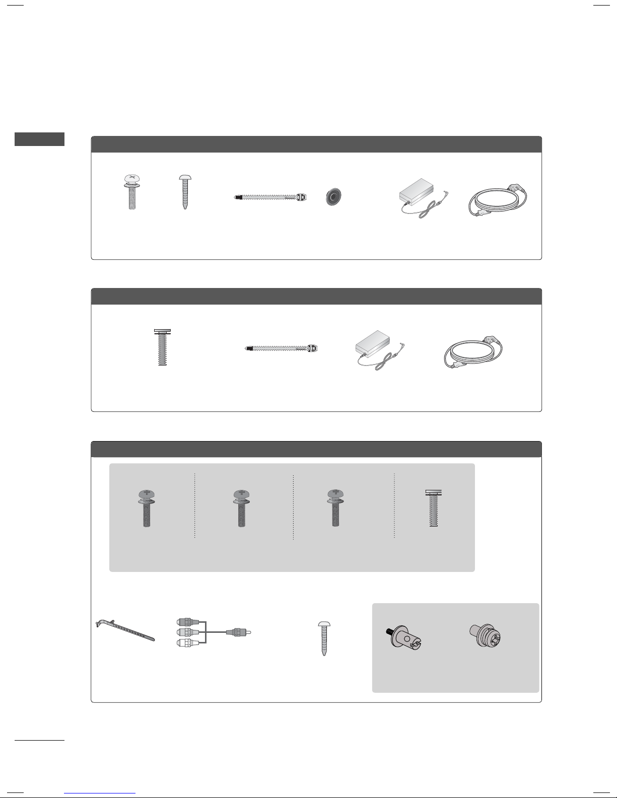
PREPARATION
PREPARATION
22/26LE5300
(For 26LE5300)
x 4
x 4
(M4 x 14) (M4 x 20)
Screws for stand assembly
(Refer to P.26, 28)
22/26LE6500
x 2
(M4 x 16)
Screws for stand assembly
(Refer to P.27)
Cable Tie
(Refer to p.36)
Cable Tie
(Refer to p.35)
(For 26LE5300)
x 4
Ring spacers
(Refer to p.32)
AC/DC Adaptor
AC/DC Adaptor
Power Cord
Power Cord
32/37/42/47/55LE5300, 32/42/47/55LE4600
(32LE5300,
32/42/47/55LE4600)
x 4
(M4 x 22)
(37/42LE5300)
x 4
(M4 x 24)
Screws for stand assembly
(Refer to P.28)
x 2
Cable Holder
(Refer to p.36)
Component gender cable,
AV gender cable
Screw for stand fixing
(47/55LE5300)
x 4
(M4 x 26)
(For 32LE5300,
32/42/47/55LE4600)
(Refer to P.38)
(M4 x 16)
(32/42/47/55LE4600)
x 2
Woofer PEM nut
(Refer to P.30)
x 4
x 2
Woofer Fixing Screw
(Refer to P.30)
10
32/37/42/47/55LE5300, 32/42/47/55LE4600
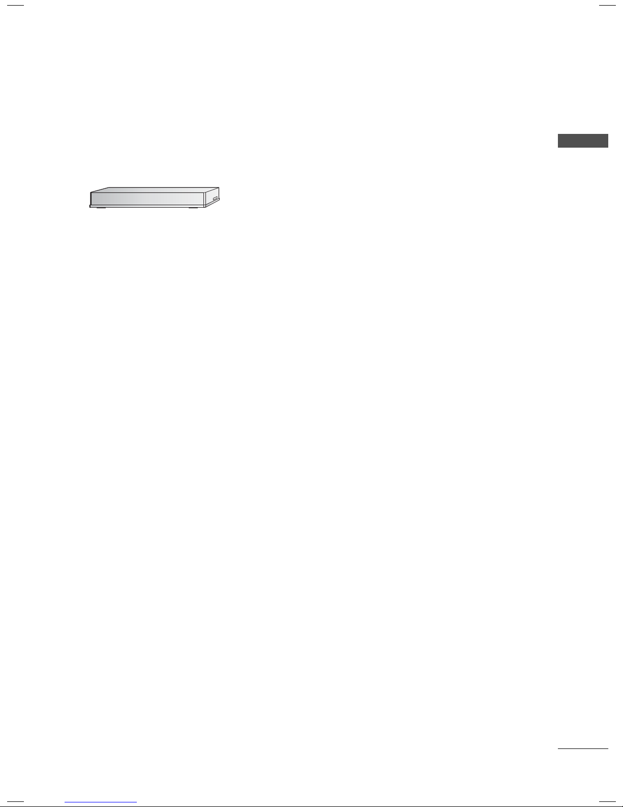
OPTIONAL EXTRAS
Optional extras can be changed or modified for quality improvement without any notification.
Contact your dealer for buying these items.
This device only works with compatible LG LED LCD TV, LCD TV, or Plasma TV.
Wireless Media Box
(AN-WL100W)
(FOR 32/37/42/47/55LE5300)
PREPARATION
11
PREPARATION
ENTER
CH
VOL
MENU
INPUT
CH
ENTER
CH
VOL
MENU
INPUT
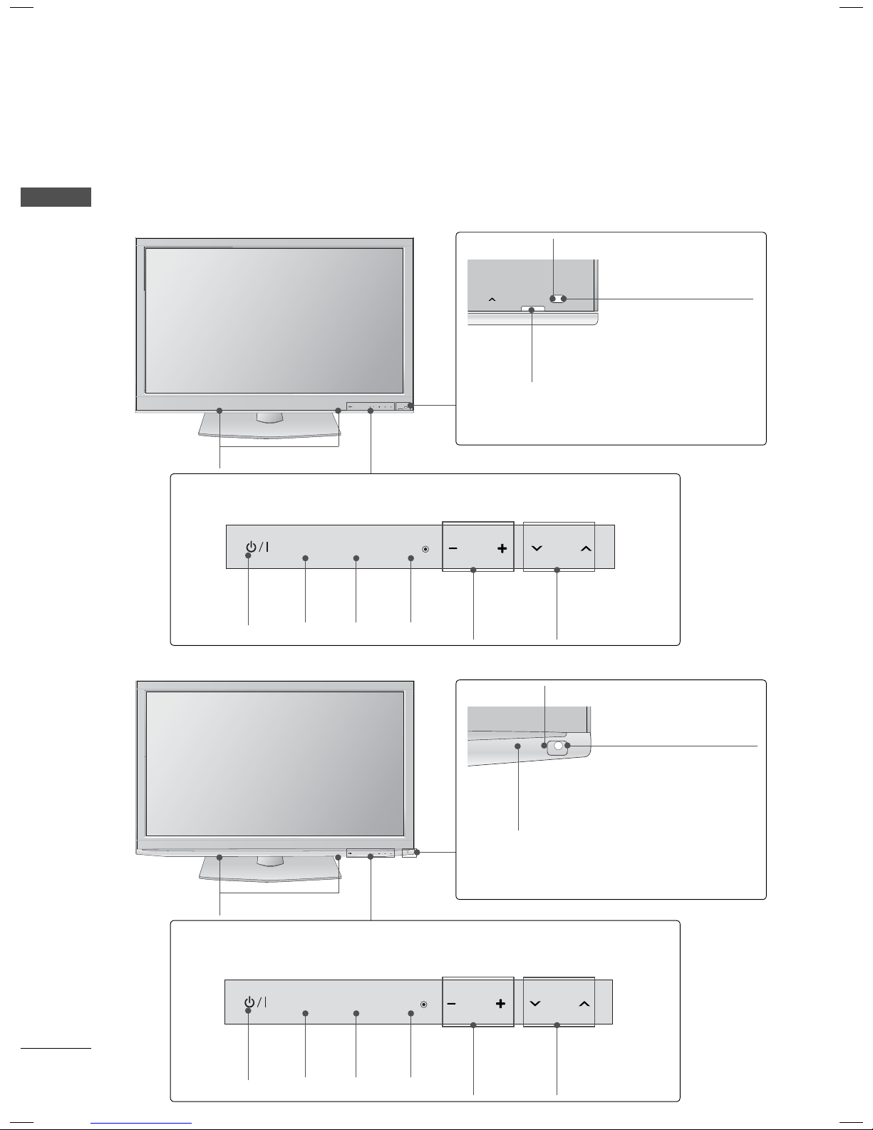
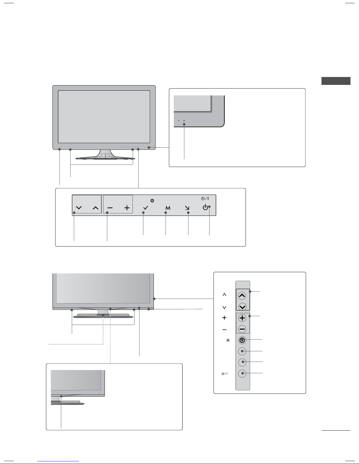
FRONT PANEL INFORMATION
ꔛ
Image shown may differ from your TV.
Plasma TV
PREPARATION
42/50PJ230, 42/50PJ250
SPEAKER
Touch Button
You can operate the button just by touching the button lightly with your finger.
Remote Control Sensor
Intelligent Sensor
Adjusts picture accord-
ing to the surrounding
conditions
Power/Standby Indicator
Illuminates red in standby mode.
The lighting is off while the TV remains on.
42/50PJ350
Touch Button
You can operate the button just by touching the button lightly with your finger.
POWER
Button
SPEAKER
INPUT
INPUT
Button
MENU
MENU
Button
ENTER
ENTER
Button
VOL
VOLUME
(+, -)
Buttons
CH
CHANNEL
(
ꕌ,ꕍ)
Buttons
Remote Control Sensor
Intelligent Sensor
Adjusts picture accord-
ing to the surrounding
conditions
Power/Standby Indicator
Illuminates red in standby mode.
The lighting is off while the TV remains on.
INPUT
POWER
Button
12
MENU
INPUT
Button
ENTER
MENU
Button
ENTER
Button
VOL
VOLUME
(+, -)
Buttons
CH
CHANNEL
(
ꕌ,ꕍ)
Buttons
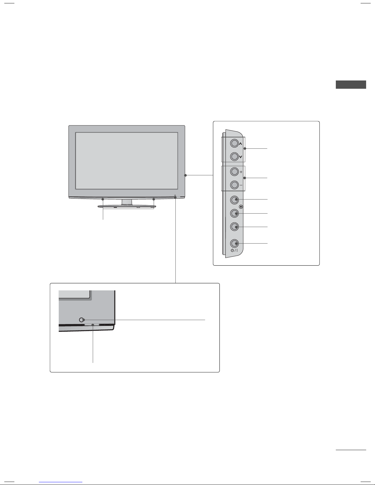
32LD350
CH
VOL
ENTER
INPUT
MENU
CHANNEL
(
ꕌ,ꕍ) Buttons
VOLUME (+, -)
Buttons
ENTER Button
PREPARATION
SPEAKER
Remote Control Sensor
Power/Standby Indicator
(Can be adjusted using the Power Indicator
in the OPTION menu.
►p.125)
MENU Button
INPUT Button
POWER Button
13
PREPARATION
CH
VOL
ENTER
INPUT
MENU
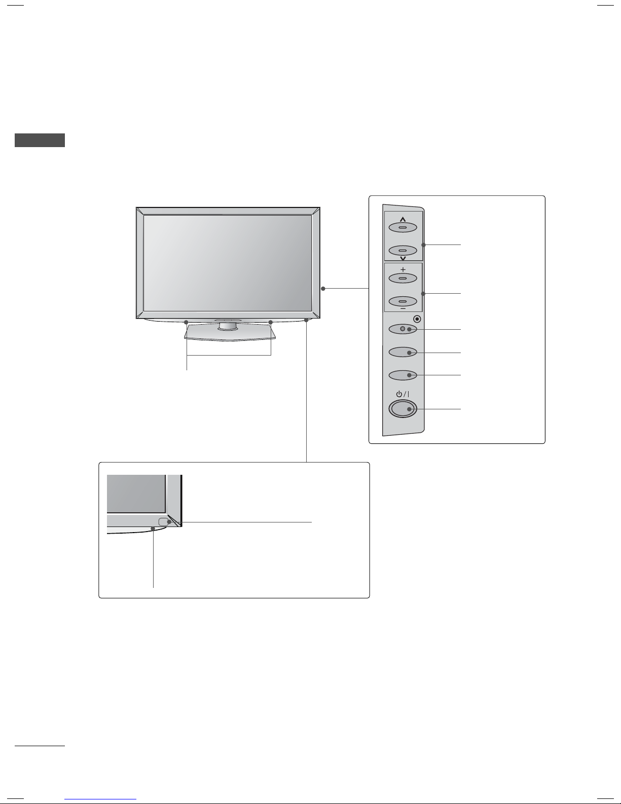
ꔛ
Image shown may differ from your TV.
PREPARATION
32/37/42/47LD460, 37/42LD461C, 32/37/42/47LD465
SPEAKER
CHANNEL
(
ꕌ,ꕍ) Buttons
VOLUME (+, -)
Buttons
ENTER Button
MENU Button
INPUT Button
Remote Control Sensor
Power/Standby Indicator
(Can be adjusted using the Power Indicator in
the OPTION menu.
►p.125)
POWER Button
14
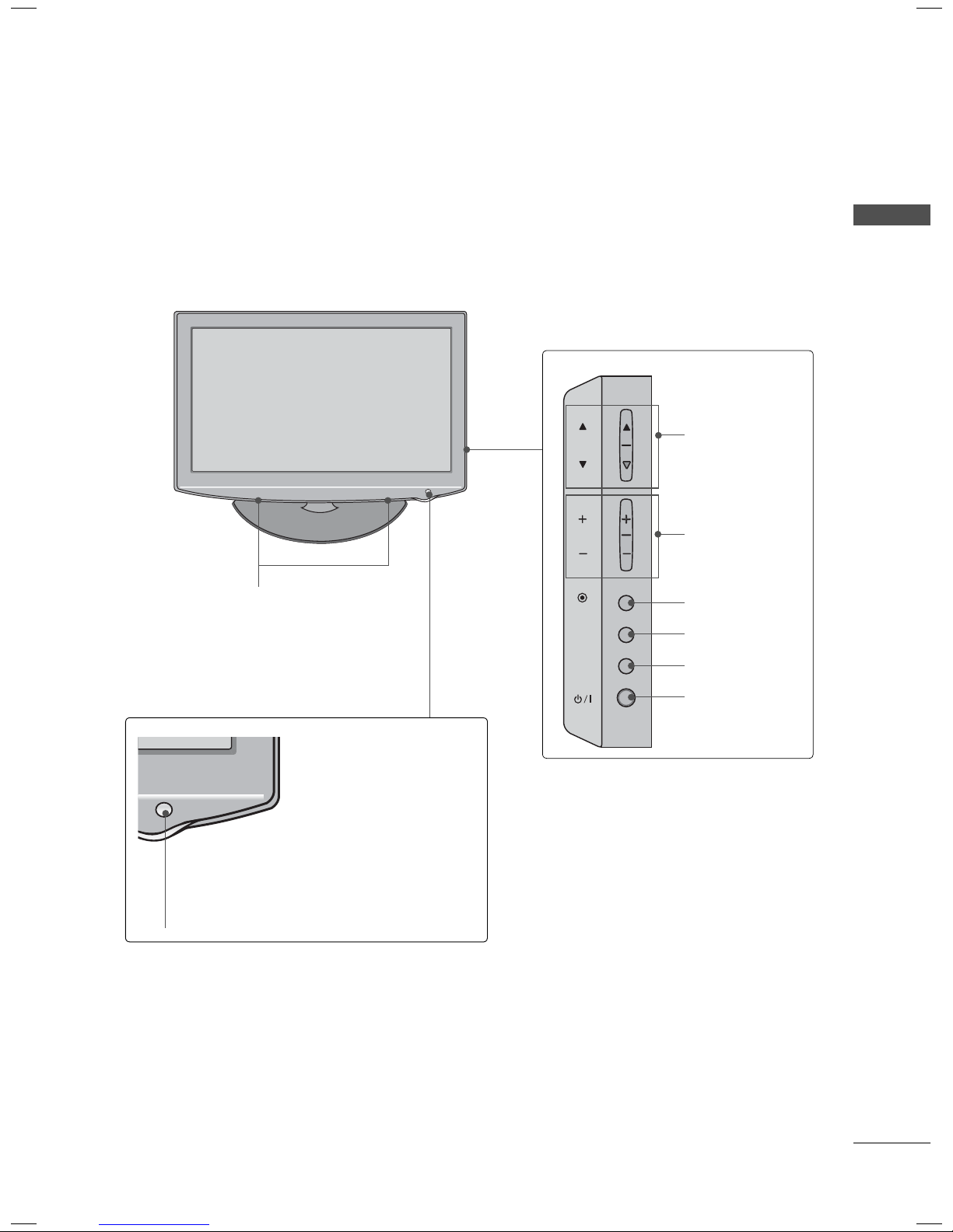
32/42LD420, 32/42LD420C
INPUT
MENU
ENTER
CH
VOL
SPEAKER
PREPARATION
CHANNEL
(▲,▼) Buttons
VOLUME (+, -)
Buttons
ENTER Button
MENU Button
INPUT Button
Remote Control Sensor
Power/Standby Indicator
(Can be adjusted using the Power Indicator
in the OPTION menu.
►p.125)
POWER Button
15
PREPARATION
VOL ENTERCH MENU INPUT
VOL ENTERCH MENU INPUT
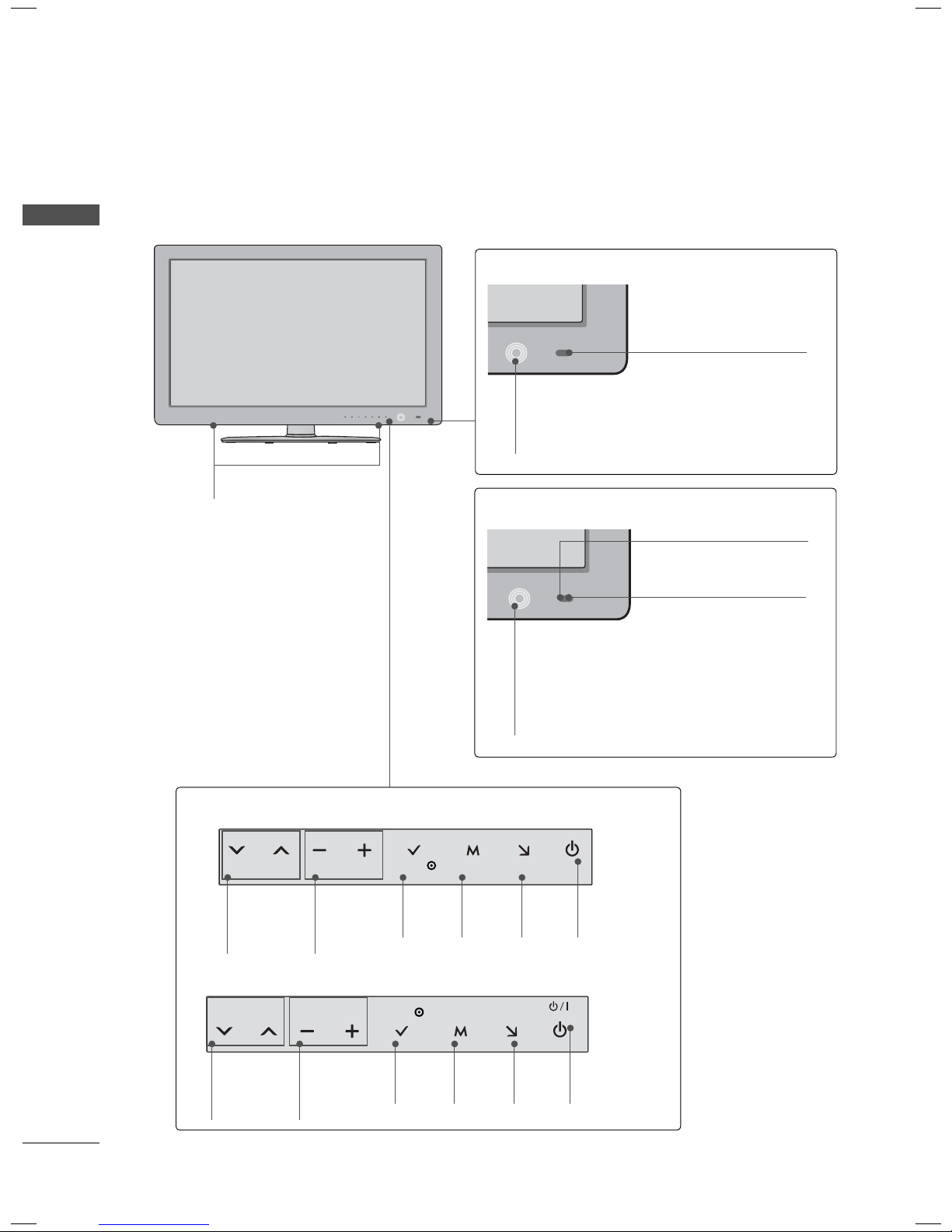
ꔛ
Image shown may differ from your TV.
22/26/32/37/42/47/55LE5300
PREPARATION
SPEAKER
22/26LE5300
Remote Control Sensor
Power/Standby Indicator
(Can be adjusted using the Power Indicator
in the OPTION menu.
►p.125)
32/37/42/47/55LE5300
22/26LE5300
CHANNEL
(
ꕍ,ꕌ)
Buttons
VOLUME
(-, +)
Buttons
32/37/42/47/55LE5300
ENTER
Button
MENU
Button
Remote Control Sensor
Intelligent Sensor
Adjusts picture according to
the surrounding conditions
Power/Standby Indicator
(Can be adjusted using the Power Indicator in
the OPTION menu.
INPUT
Button
POWER
Button
►p.125)
CHANNEL
(
ꕍ,ꕌ)
Buttons
VOLUME
(-, +)
Buttons
16
ENTER
Button
MENU
Button
INPUT
Button
POWER
Button
22/26LE6500
CH
ENTER
INPUT
MENU
VOL
VOL ENTERCH MENU INPUT
SPEAKER
Remote Control Sensor
Power/Standby Indicator
(Can be adjusted using the Power Indicator
in the OPTION menu.
►p.125)
PREPARATION
CHANNEL
(
ꕍ,ꕌ)
Buttons
32/42/47/55LE4600
SPEAKER
WOOFER
VOLUME
(-, +)
Buttons
ENTER
Button
MENU
Button
INPUT
Button
Intelligent Sensor
Adjusts picture accord-
ing to the surrounding
conditions.
Remote Control Sensor
POWER
Button
CHANNEL
(▲,▼) Buttons
VOLUME (+, -)
Buttons
ENTER Button
MENU Button
INPUT Button
POWER Button
Power/Standby Indicator
(Can be adjusted using the Power Indicator
in the OPTION menu.
►p.125)
17
PREPARATION
ANTENNA IN CABLE IN
VIDEO
AUDIO
L(MONO)
R
Y
LR
P
B
P
R
2
1
1
VIDEO
AUDIO
RGB IN (PC)
RS-232C IN
(
CONTROL&SERVICE)
AUDIO IN
(RGB/DVI)
OPTICAL DIGITAL
AUDIO OUT
/DVI IN
AV IN 1
COMPONENT IN
IN 2
USB IN
AV IN 2
VIDEO
AUDIO
L(MONO)
R
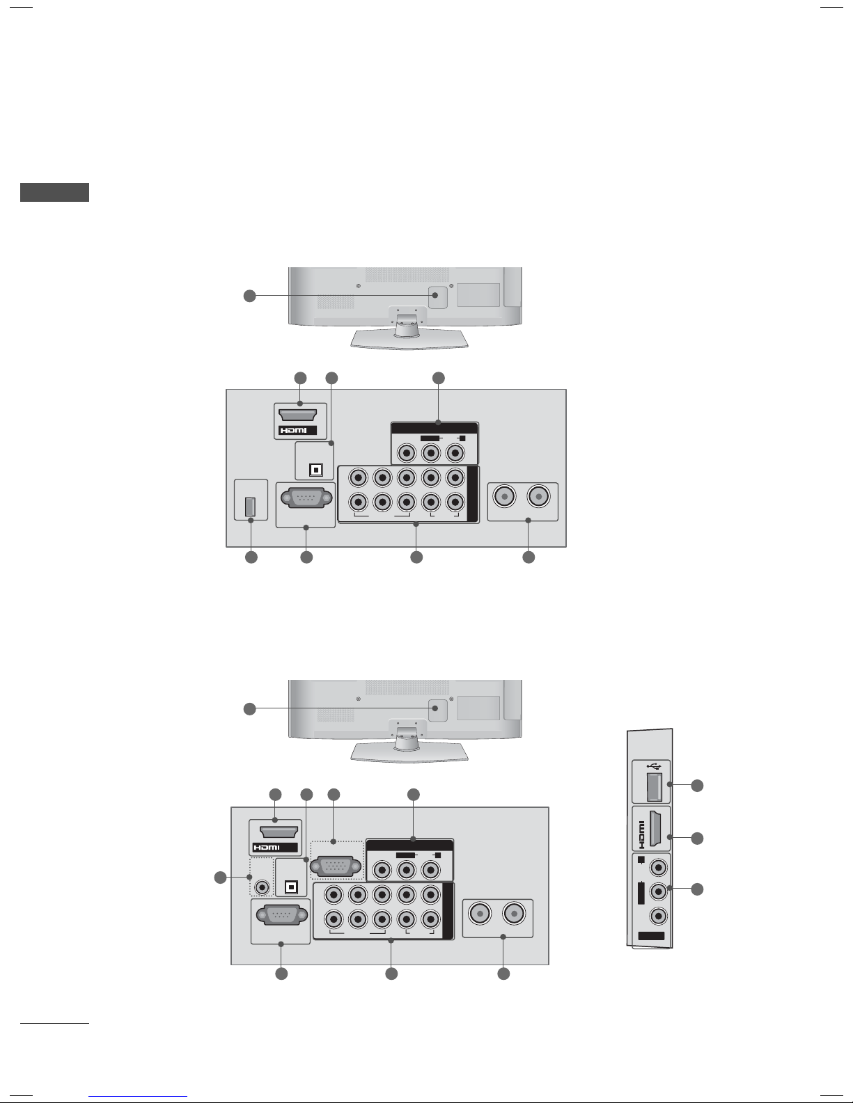
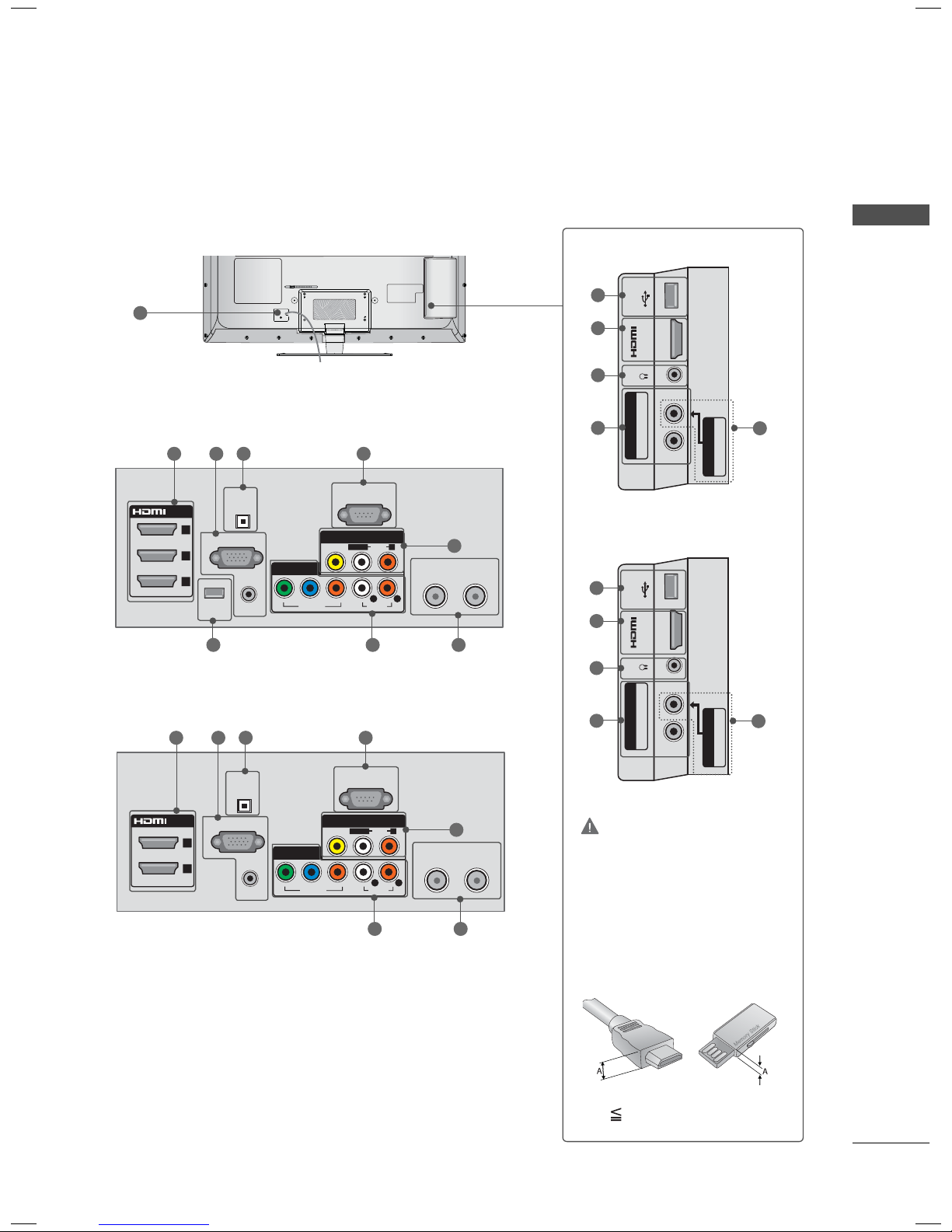
BACK PANEL INFORMATION
ꔛ
Image shown may differ from your TV.
PREPARATION
42/50PJ230
12
OPTICAL DIGITAL
SERVICE
ONLY
RS-232C IN
(
CONTROL&SERVICE)
42/50PJ250, 42/50PJ350
12
1
IN
AUDIO OUT
411
2
2
Y
B
P
VIDEO
P
R
AV IN
L(MONO)
3
AUDIO
R
LR
1
ANTENNA IN CABLE IN
COMPONENT IN
VIDEO
AUDIO
6
5
1
7
18
4
72
3
9
1
3
6
5
32LD350, 32/37/42/47LD460, 37/42LD461C, 32/37/42/47LD465, 32/42LD420, 32/42LD420C
AC IN
VIDEO
AUDIO
RGB IN (PC)
AUDIO IN
(RGB/DVI)
RS-232C IN
(
CONTROL&SERVICE)
OPTICAL
DIGITAL
AUDIO OUT
/DVI IN
ANTENNAINCABLE IN
1
YPBP
R
L R
VIDEO
AUDIO
L/MONO
R
COMPONENT IN
AV IN 1
IN 2
H/P USB IN
SERVICE ONLY
AV IN 2
VIDEO
AUDIO
L/MONO
R
IN 2
H/P USB IN
AV IN 2
VIDEO
AUDIO
L/MONO
R
PREPARATION
12
12
32/37/42/47LD460,
37/42LD461C,
32/37/42/47LD465,
32/42LD420,
32LD350
432
1
32/42LD420C
11 9
1 1
10 10
3 3
7
56
19
PREPARATION
H/P
USB IN
IN 3
H/P USB IN
H/P USB IN
IN 3
ANTENNA
IN
DC-IN
CABLE IN
RGB IN (PC)
AUDIO IN
RGB/DVI
(DVI)
OPTICAL
DIGITAL
AUDIO OUT
/DVI IN
VIDEO
AUDIO
L(MONO)
R
VIDEO
AUDIO
YPB PR
L R
COMPONENT IN
AV IN
RS-232C IN
(
CONTROL&SERVICE)
1 2
DC INDC IN
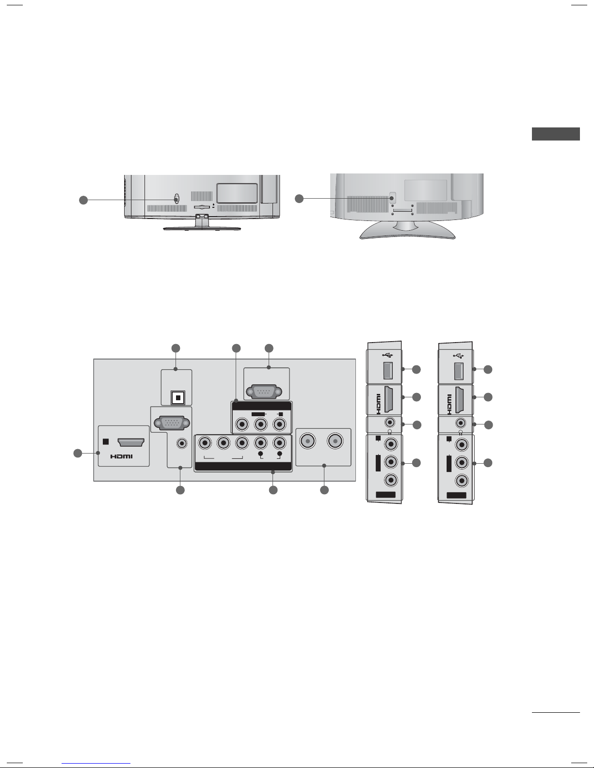
PREPARATION
22/26LE5300, 22/26LE6500
13 1 27 4
22LE5300
26LE5300
9
22/26LE6500
9
9
3
1
10
10
1
10
56
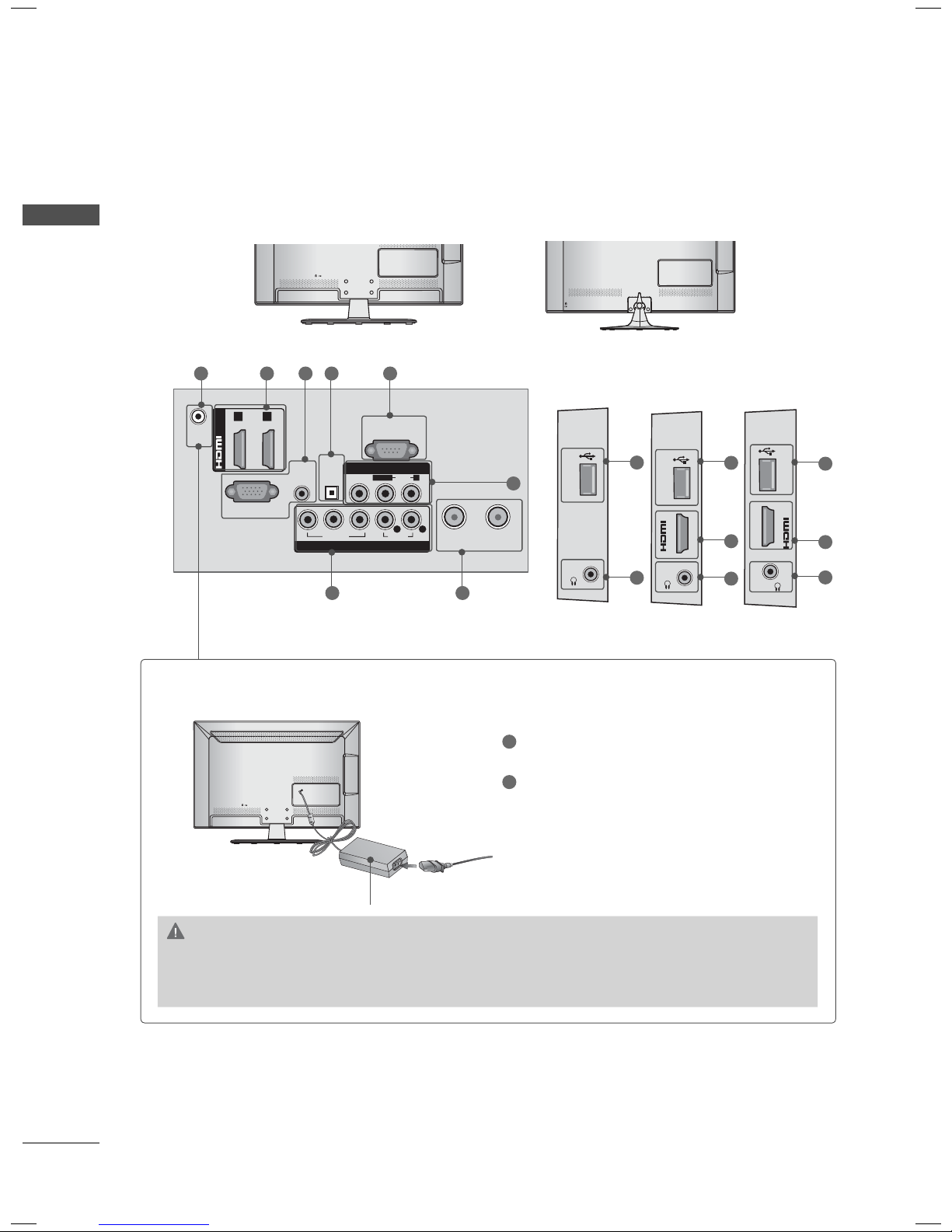
Power Connection
CAUTION
► Please be sure to connect the TV to the AC/DC power adapter before connecting the TV’s
power plug to a wall power outlet.
20
AC/DC Adaptor
1
Connect the AC/DC adapter plug to the
power input jack on the TV.
2
Connect the power cord to the AC/DC
adapter first, then plug the power cord into
the wall power outlet.
32/37/42/47/55LE5300, 32/42/47/55LE4600
COMPONENT IN2
Y P
B PR / AUDIO
IN 4
H/P
USB IN
AV IN2
VIDEO / AUDIO
(RGB/DVI)
(DVI)
/DVI IN
2
3
1
AUDIO IN
WIRELESS
CONTROL
ꔡ
RGB IN (PC)
RS-232C IN
(CONTROL &
SERVICE)
OPTICAL
DIGITAL
AUDIO OUT
VIDEO
AUDIO
L/MONO
R
VIDEO
AUDIO
COMPONENT IN 1
AV IN 1
YPB PR
L R
ANTENNA INCABLE IN
(RGB/DVI)
/DVI IN
2
(DVI)
1
AUDIO IN
RGB IN (PC)
RS-232C IN
(CONTROL &
SERVICE)
OPTICAL
DIGITAL
AUDIO OUT
VIDEO
AUDIO
L/MONO
R
VIDEO
AUDIO
COMPONENT IN 1
AV IN 1
YPBP
R
L R
ANTENNAINCABLE
IN
COMPONENT IN2
Y P
B PR / AUDIO
IN 3
H/P
USB IN
AV IN2
VIDEO / AUDIO
12
32/37/42/47/55LE5300
32/37/42/47/55LE5300
9
1
10
PREPARATION
32/37/42/47/55LE5300
1 7 2 4
32/42/47/55LE4600
1 7 2 4
68 5
6 5
6
3
32/42/47/55LE4600
3
9
1
10
6
3
CAUTION
3
For HDMI IN 3, 4 and USB IN
► For an optimal connection,
HDMI cables and USB
devices should have bezels
less than 10 mm (0.39
inches) thick.
*A 10 mm (0.39 inches)
21

PREPARATION
PREPARATION
1
HDMI/DVI IN, HDMI IN
Digital Connection.
Supports HD video and Digital audio. Doesn’t
support 480i.
Accepts DVI video using an adapter or HDMI
to DVI cable (not included).
2
OPTICAL DIGITAL AUDIO OUT
Digital optical audio output for use with amps
and home theater systems.
Note: In standby mode, this port doesn’t work.
3
AV (Audio/Video) IN
Analog composite connection. Supports stan-
dard definition video only (480i).
4
RS-232C IN (CONTROL & SERVICE) PORT
Used by third party devices.
This port is used for service or Hotel mode.
5
ANTENNA IN/CABLE IN
Connect over-the air signals to this jack.
Connect cable signals to this jack.
6
COMPONENT IN
Analog Connection.
Supports HD.
Uses a red, green, and blue cable for video &
red and white for audio.
7
RGB IN (PC)
Analog PC Connection. Uses a D-sub 15 pin
cable (VGA cable).
AUDIO IN (RGB/DVI)
1/8” (0.32 cm) headphone jack for analog PC
audio input.
8
WIRELESS CONTROL
Connect the Wireless Dongle to the TV to
control the external input devices connected
to Media Box wirelessly.
9
USB INPUT
Used for viewing photos, movies and listen-
ing to MP3s.
10
HEADPHONE INPUT
0.32 cm (1/8 inch) headphone jack
Impedance 16 Ω , Maximum audio out 15 mW
11
SERVICE ONLY, USB IN SERVICE ONLY
This port is used for service.
12
Power Cord or Socket
For operation with AC power.
Caution: Never attempt to operate the TV on
DC power.
13
DC IN
22
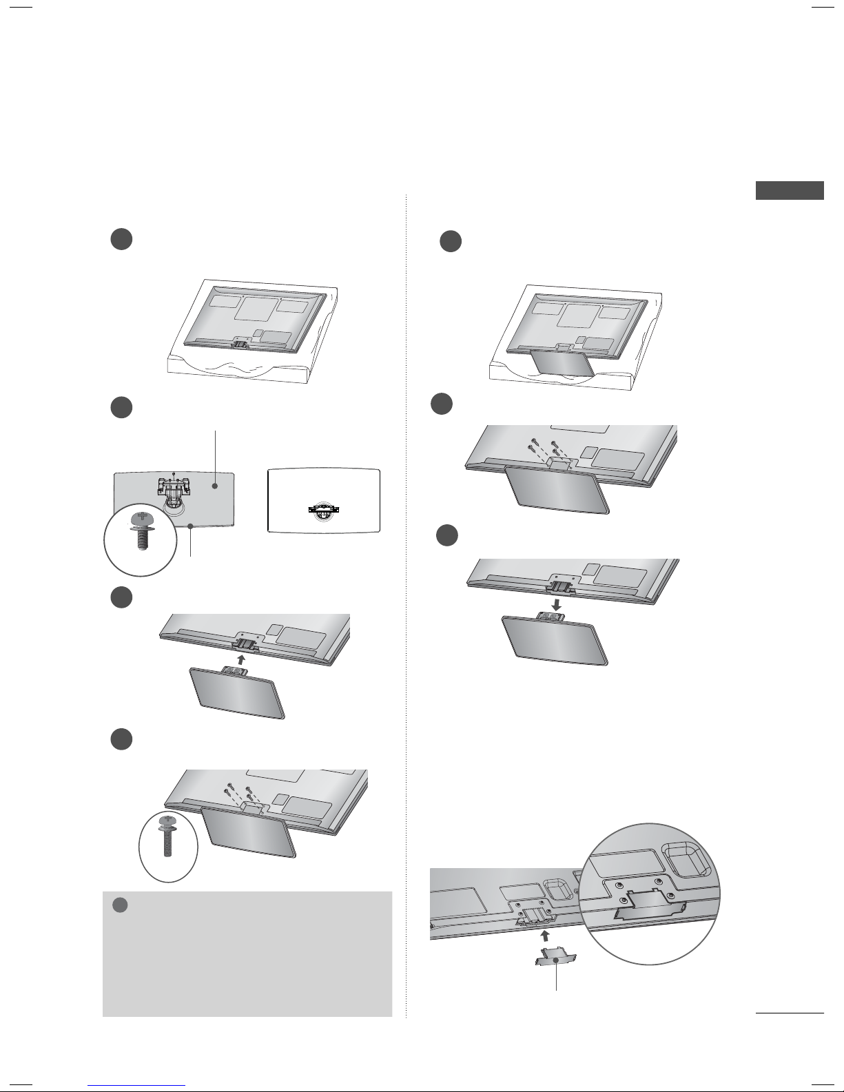
STAND INSTRUCTIONS
!
ꔛ
Image shown may differ from your TV.
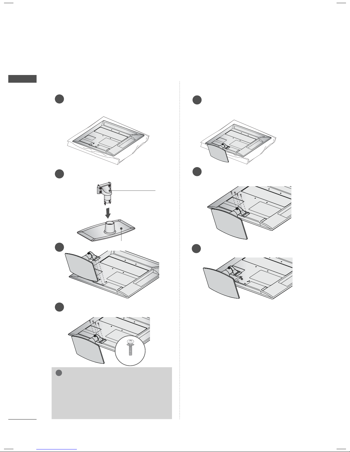
(For Plasma TV)
INSTALLATION
Carefully place the TV screen side down
1
on a cushioned surface to protect the
screen from damage.
Assemble the parts of the STAND BODY
2
with the STAND BASE of the TV.
STAND BODY
M5 x 14
Assemble the TV as shown.
3
STAND BASE
DETACHMENT
Carefully place the TV screen side down
1
on a cushioned surface to protect the
screen from damage.
Remove the screws that hold the stand on.
2
Detach the stand from TV.
3
PREPARATION
Fix the 4 screws securely using the holes
4
in the back of the TV.
M4 x 28
NOTE
► When assembling the desk type stand,
make sure the screws are fully tightened (If
not tightened fully, the TV can tilt forward
after the product installation). Do not over
tighten.
PROTECTION COVER
After removing the stand, install the included
PROTECTION COVER over the hole for the
stand.
Press the PROTECTION COVER into the TV
until you hear it click.
When installing the wall mounting bracket, use
the PROTECTION COVER.
PROTECTION COVER
Fix a guide to the outside.
23
PREPARATION
!
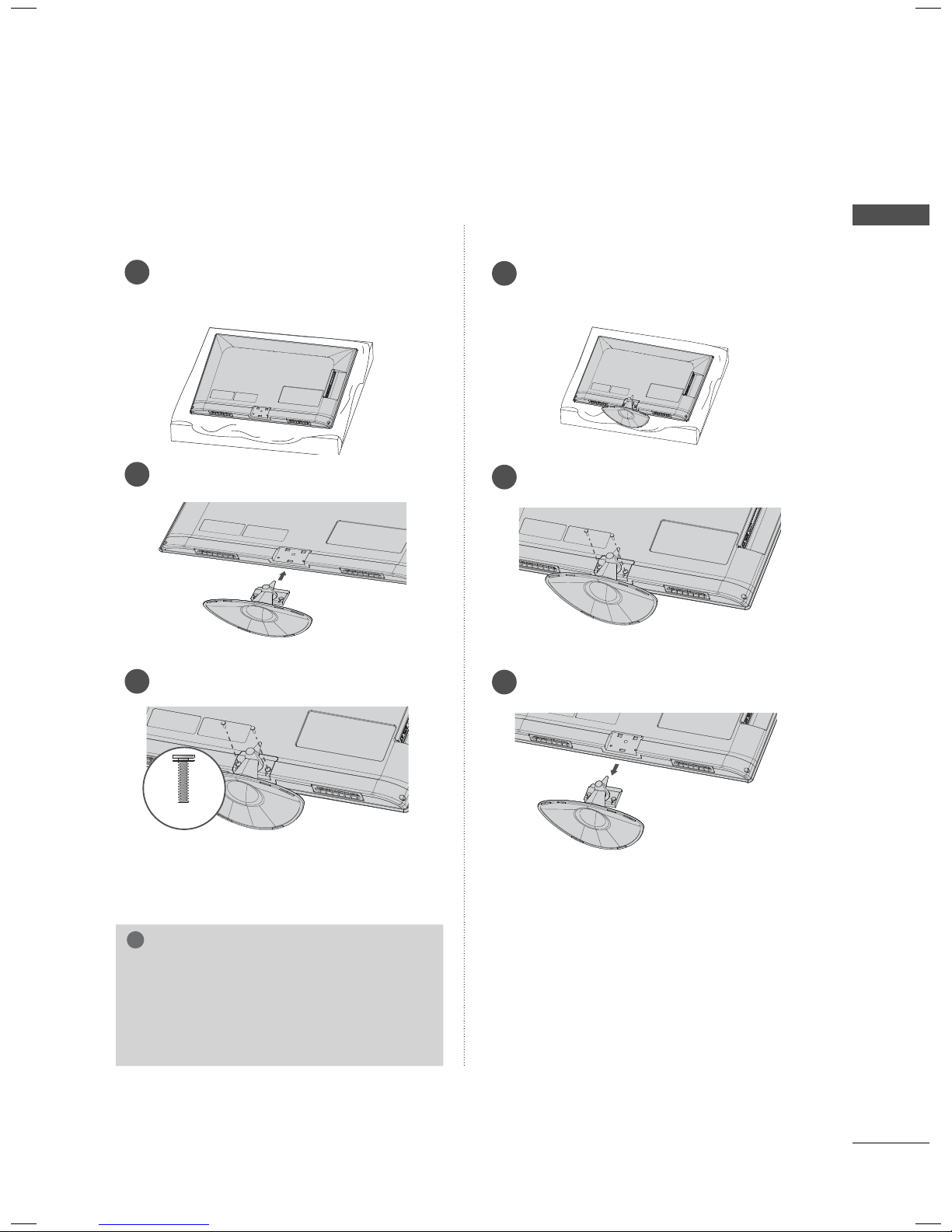
STAND INSTRUCTIONS (For 32LD350, 32/37/42/47LD460, 37/42LD461C, 32/37/42/47LD465)
ꔛ
Image shown may differ from your TV.
PREPARATION
INSTALLATION
Carefully place the TV screen side down on
1
a cushioned surface to protect the screen
from damage.
Assemble the parts of the STAND BODY
2
with the STAND BASE of the TV.
STAND BODY
M4 x 20
STAND BASE
Assemble the TV as shown.
3
DETACHMENT
Carefully place the TV screen side down
1
on a cushioned surface to protect the
screen from damage.
Remove the screws that hold the stand
2
on.
Detach the stand from TV.
3
Fix the 4 screws securely using the holes in
4
the back of the TV.
NOTE
► When assembling the desk type stand,
make sure the screws are fully tightened
(If not tightened fully, the TV can tilt forward after the product installation). Do
not over tighten.
24
M4 x 20
PROTECTION COVER
After removing the stand, install the included
PROTECTION COVER over the hole for the
stand.
Press the PROTECTION COVER into the TV
until you hear it click.
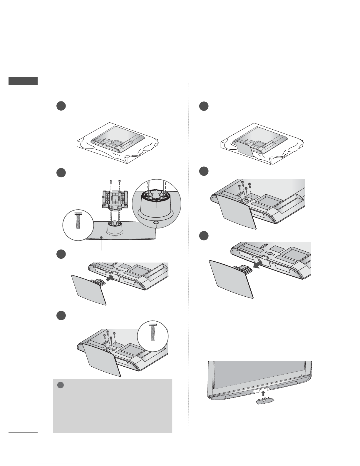
STAND INSTRUCTIONS
!
ꔛ
Image shown may differ from your TV.
(For
32/42LD420, 32/42LD420C
)
INSTALLATION
Carefully place the TV screen side down
1
on a cushioned surface to protect the
screen from damage.
Assemble the TV as shown.
2
Install the 4 screws into the holes shown.
3
DETACHMENT
Carefully place the TV screen side down on
1
a cushioned surface to protect the screen
from damage.
Remove the screws that hold the stand on.
2
Detach the stand from TV.
3
PREPARATION
M4 x 24
NOTE
► When assembling the desk type stand,
make sure the screws are fully tightened
(If not tightened fully, the TV can tilt forward after the product installation). Do not
over tighten.
PROTECTION COVER
After removing the stand, install the included
PROTECTION COVER over the hole for the
stand.
Press the PROTECTION COVER into the TV until
you hear it click.
When installing the wall mounting bracket, use
the PROTECTION COVER.
25
PREPARATION
!
PREPARATION
STAND INSTRUCTIONS
ꔛ
Image shown may differ from your TV.
(For 22LE5300)
INSTALLATION
Carefully place the TV screen side down
1
on a cushioned surface to protect the
screen from damage.
Assemble the parts of the STAND BODY
2
with the STAND BASE of the TV.
STAND BODY
DETACHMENT
Carefully place the TV screen side down
1
on a cushioned surface to protect the
screen from damage.
Remove the screws that hold the stand
2
on.
STAND BASE
Assemble the TV as shown.
3
Fix the 4 screws securely using the holes
4
in the back of the TV.
M4 x 14
NOTE
► When assembling the desk type stand,
make sure the screws are fully tightened (If
not tightened fully, the TV can tilt forward
after the product installation). Do not over
tighten.
Detach the stand from TV.
3
26
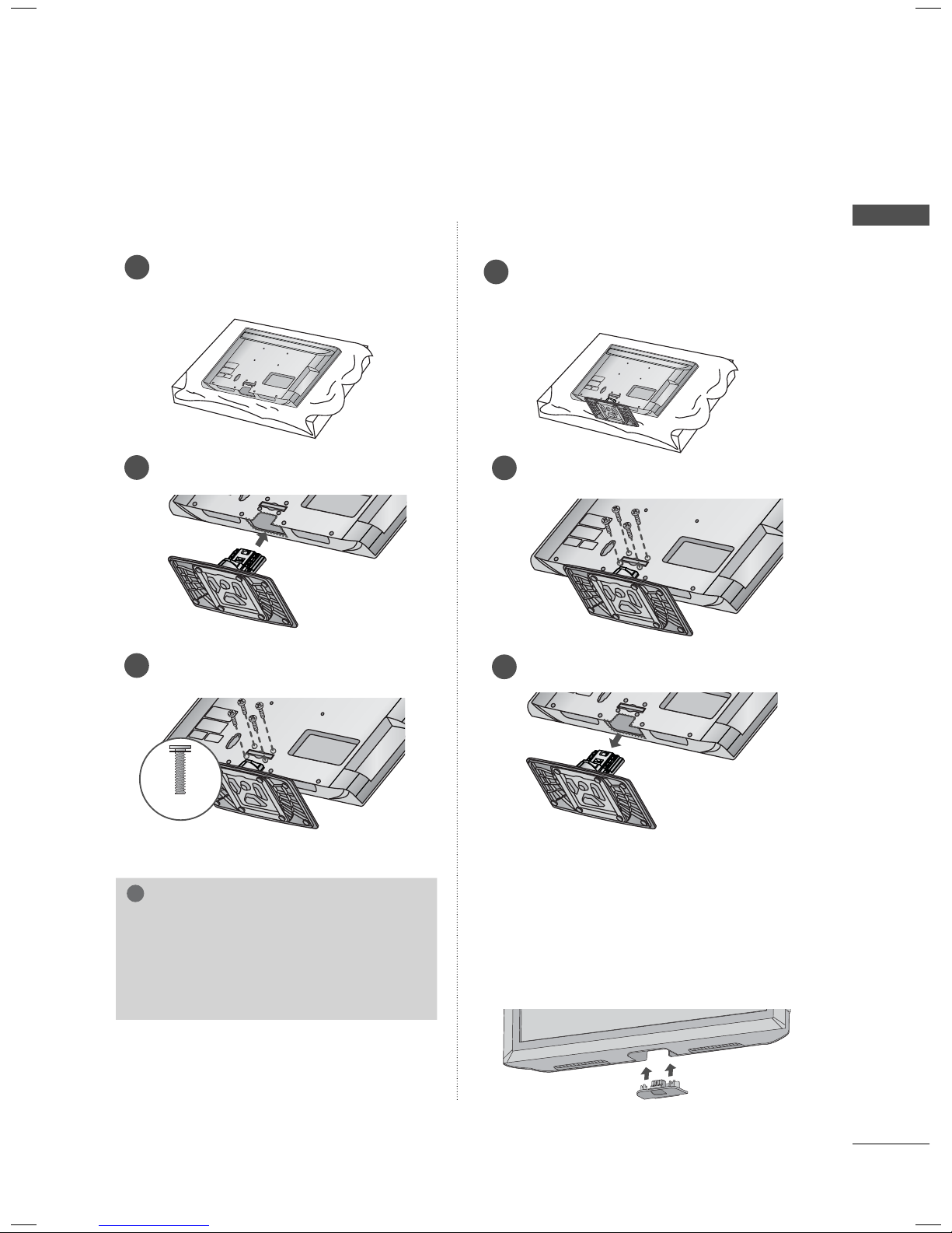
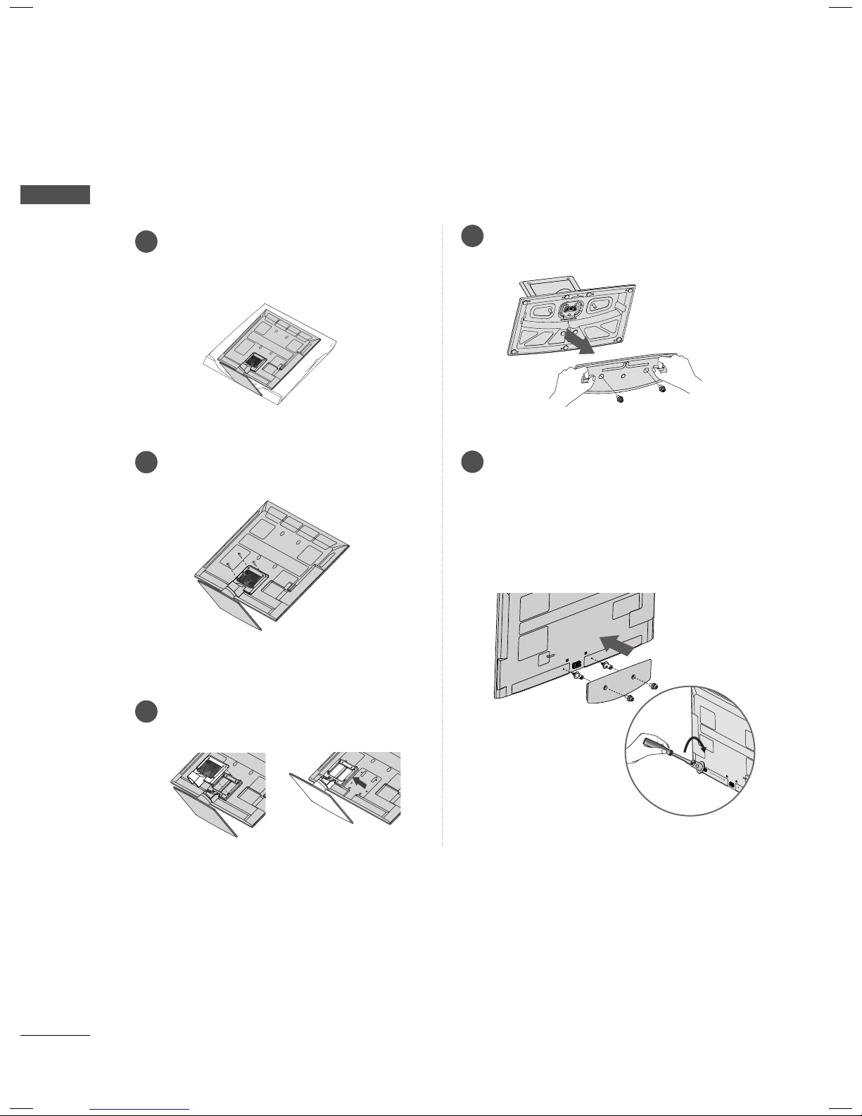
STAND INSTRUCTIONS
!
ꔛ
Image shown may differ from your TV.
(For
22/26LE6500
)
INSTALLATION
Carefully place the TV screen side down
1
on a cushioned surface to protect the
screen from damage.
Assemble the TV as shown.
2
DETACHMENT
Carefully place the TV screen side down
1
on a cushioned surface to protect the
screen from damage.
Remove the screws that hold the stand on.
2
PREPARATION
Install the 2 screws into the holes shown.
3
M4 x 16
NOTE
► When assembling the desk type stand,
make sure the screws are fully tightened (If
not tightened fully, the TV can tilt forward
after the product installation). Do not over
tighten.
Detach the stand from TV.
3
27
PREPARATION
!
PREPARATION
STAND INSTRUCTIONS
ꔛ
Image shown may differ from your TV.
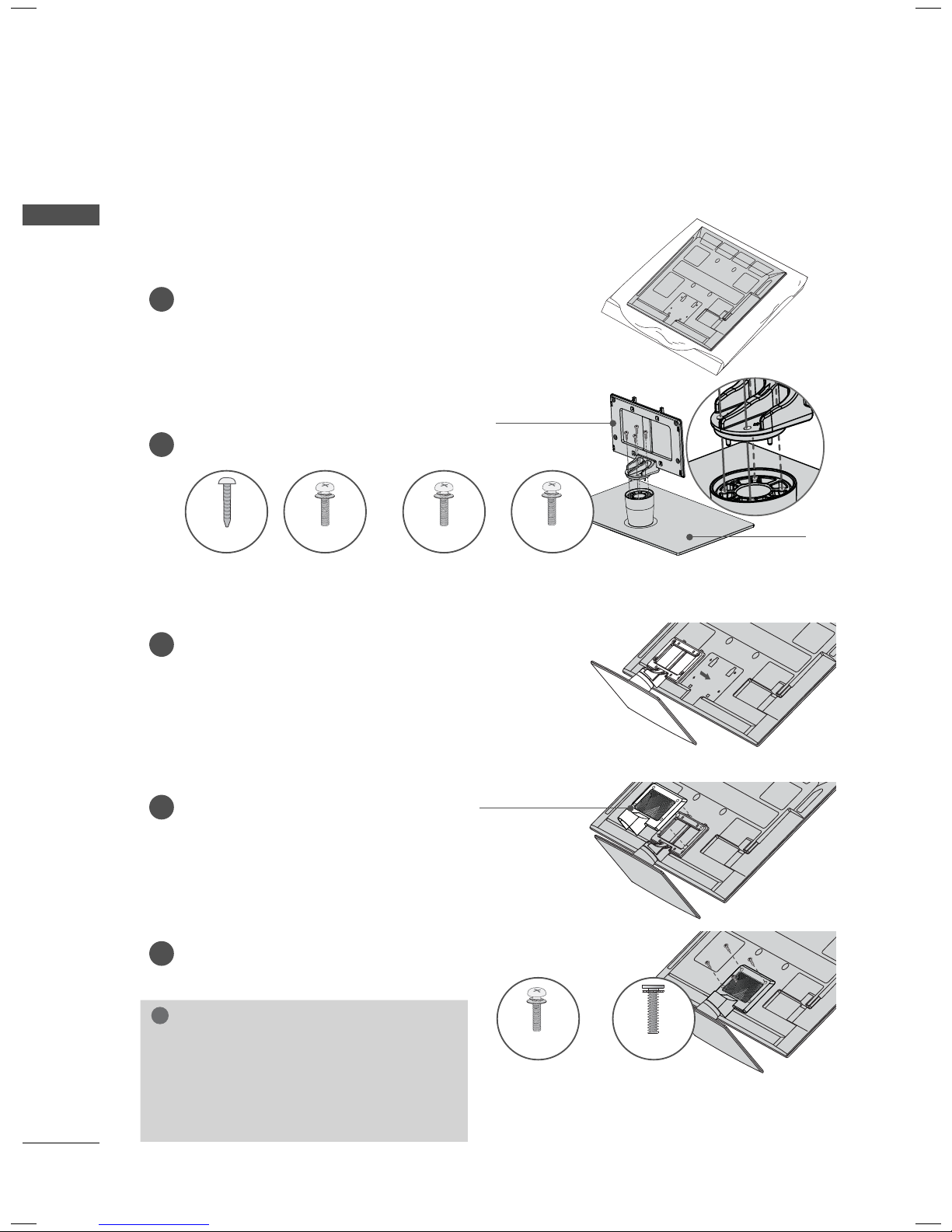
(For 26/32/37/42/47/55LE5300, 32/42/47/55LE4600)
INSTALLATION
1
Carefully place the TV screen side down on
a cushioned surface to protect the screen
from damage.
Assemble the parts of the STAND BODY
2
with the STAND BASE of the TV.
M4 x 22 M4 x 24 M4 x 26M4 x 20
26LE5300
32LE5300,
32/42/47/55LE4600
37/42LE5300 47/55LE5300
STAND BODY
STAND BASE
Assemble the TV as shown.
3
Assemble the part of the STAND
4
REAR COVER with the TV.
5
Install the 4 screws into the holes shown.
NOTE
► When assembling the desk type stand,
make sure the screws are fully tightened (If
not tightened fully, the TV can tilt forward
after the product installation). Do not over
tighten.
STAND REAR
COVER
For 26LE5300
M4 x 16M4 x 14
Other models
28
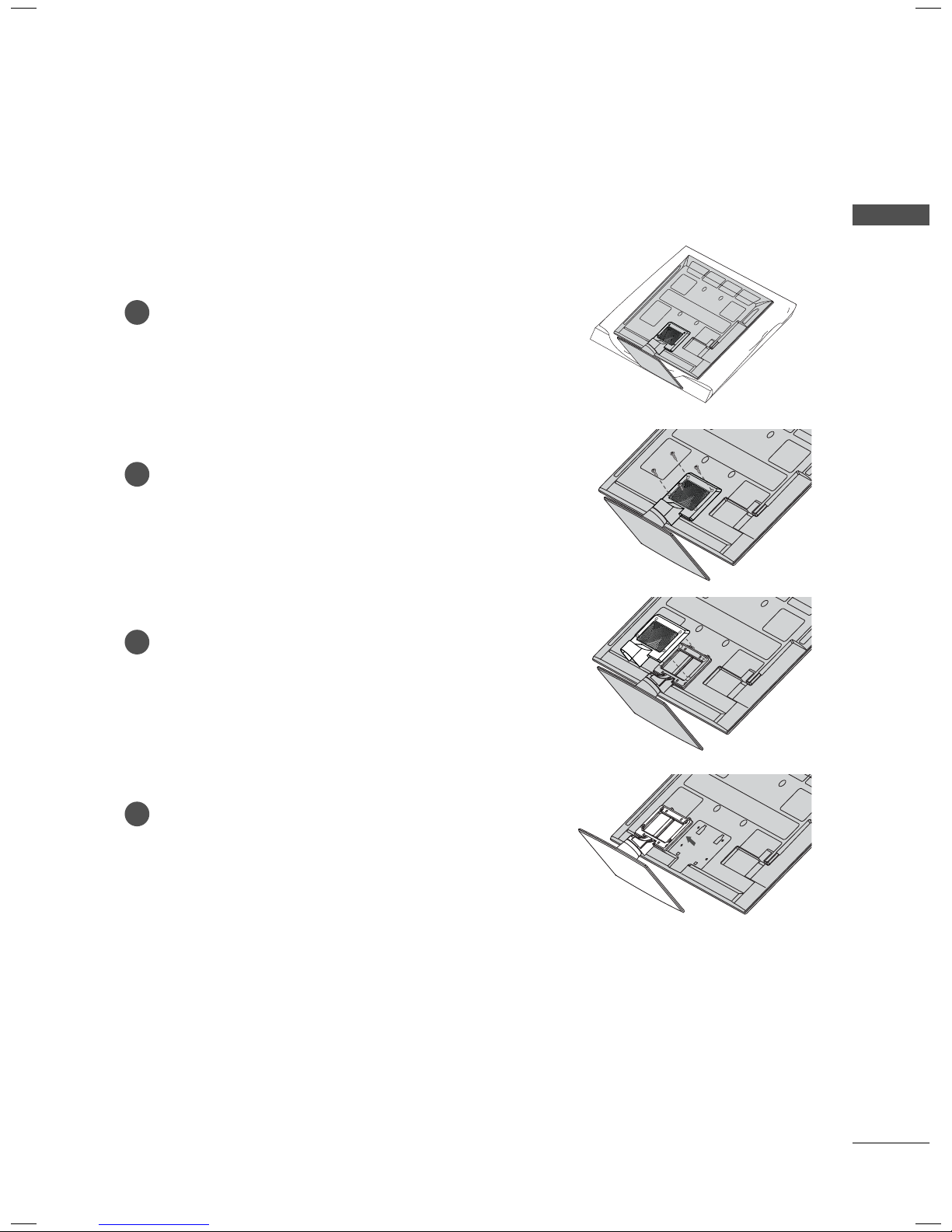
DETACHMENT
Carefully place the TV screen side down on
1
a cushioned surface to protect the screen
from damage.
Remove the screws that hold the stand on.
2
Detach the STAND REAR COVER from TV.
3
PREPARATION
Detach the stand from TV.
4
29
PREPARATION
WOOFER INSTALLATION: WHEN USING THE WALL
MOUNT (For 32/42/47/55LE4600)
PREPARATION
Carefully place the TV screen side down
1
on a cushioned surface to protect the
screen from damage.
Remove the screws from the TV.
2
Detach the WOOFER from the stand.
4
Assemble the WOOFER with the TV.
5
Turn the PEM nut for the woofer using a
flathead driver and install the 2 screws as
shown.
When installing the woofer in the TV, make
sure that the power cord is not twisted,
bent or pinched.
Detach the STAND REAR COVER and
3
STAND from TV.
30
 Loading...