

Page 1

Drawn Approved
Signature
Danbi.Park Jongok.kim
MMM/DD/YYYY
Feb/17/2014 Feb/17/2014
LB67-Z LG MFL68027018
EK LB670V (1402-REV00)
:LGEAK :LGEKR :LGERS
:LGEAZ :LGEMA :LGESY
:LGEEG :LGEMX :LGETH
:LGEIL :LGEND :LGEVN
:LGEIN :LGERA :LGEWR
:LGEAS
Printed in Indonesia
Printed in Russia
Printed in Poland
Signature
Change Contents
ECO Number
N
O
T
E
“This part contains Eco-hazardous substances (Pb, Cd, Hg, Cr6+, PBB, PBDE, etc.) within LG standard level,
Details should be followed Eco-SCM management standard[LG(56)-A-2524].
Especially, Part should be followed and controlled the following specification.
(1) Eco-hazardous substances test report should be submitted when Part certification test and First Mass Production.
(2) Especially, Don’t use or contain lead(Pb) and cadmium(Cd) in ink.
Printed in China
Printed in China
Printed in Thailand
Printed in Vietnam
Rev. Number
MMM/DD/YYYY
60
148 mm x 210 mm (A5)
1 Color (Black)
1 Color (Black)
Uncoated, wood-free paper 60 g/㎡
Uncoated, wood-free paper 60 g/㎡
Saddle stitching
ENG-UK (1)
3. Origin Notification
4. Changes
Printed in Mexico
Printed in Egypt
Printed in India
Printed in Algeria
3. Stock (Paper)
: • Cover
Printed in Mexico
Printed in Poland
Printed in Kazakhstan
Printed in Brazil
:5. Language
:6. Number of pages
:Model name
:2nd, 3rd Suffix
:Brand name
:Product name
:1. Trim size (Format)
2. Printing colors
: • Cover
: • Inside
Printed in Korea
: • Inside
:4. Bindery
(Revision number)
2. Printing Specification
Checked
Feb/17/2014
Mira.Woo
:Part number
1. Model Description
Printing specification
1
10
9
8
7
6
5
4
3
2
Page 2

Front Back
(Eng)
P/No. 2 … 56 Blank Blank Blank
Pagination sheet
60 pages
:Total pages
:Part number
MFL68027018
Page 3

OWNER’S MANUAL
*
LED TV
* LG LED TV applies LCD
screen with LED backlights.
Click! User Guide
Please read this manual carefully before operating your set and retain
it for future reference.
LB63** LB69** LB87**
LB65** LB72**
LB67** LB73**
LB68** LB86**
*MFL68027018*
P/NO : MFL68027018(1402-REV00)
Printed in Korea
www.lg.com
Page 4

2
TABLE OF CONTENTS
ENGLISH
TABLE OF CONTENTS
3 LICENSES
3 OPEN SOURCE SOFTWARE
NOTICE
3 EXTERNAL CONTROL DEVICE
SETUP
4 SAFETY INSTRUCTIONS
10 - Viewing 3D Imaging (Only 3D models)
12 INSTALLATION PROCEDURE
12 ASSEMBLING AND PREPARING
12 Unpacking
16 Separate purchase
17 Parts and buttons
19 - Using the Joystick button
20 Lifting and moving the TV
21 Setting up the TV
21 - Attaching the stand
26 - Attaching the Sound Bar Supporter
28 Mounting on a table
29 Mounting on a wall
30 Tidying cables
31 Using Built-in Camera
32 - Preparing Built-in Camera
32 - Name of Parts of Built-in Camera
32 - Checking the Camera’s Shooting
Range
33 MAKING CONNECTIONS
33 Antenna connection
34 Satellite dish connection
34 HDMI connection
35 Headphone connection
36 DVI to HDMI connection
37 Component connection
38 Composite connection
39 MHL connection
39 Audio connection
39 - Digital optical audio connection
40 USB connection
40 CI module connection
41 Euro Scart connection
42 REMOTE CONTROL
44 MAGIC REMOTE FUNCTIONS
45 Registering Magic Remote
45 How to use Magic Remote
46 Precautions to Take when Using the
Magic Remote
46 USING THE USER GUIDE
47 MAINTENANCE
47 Cleaning your TV
47 - Screen, frame, cabinet and stand
47 - Power cord
47 TROUBLESHOOTING
48 SPECIFICATIONS
WARNING
If you ignore the warning message, you
y
may be seriously injured or there is a
possibility of accident or death.
CAUTION
yIf you ignore the caution message, you
may be slightly injured or the product may
be damaged.
NOTE
The note helps you understand and use
y
the product safely. Please read the note
carefully before using the product.
Page 5

LICENSES / OPEN SOURCE SOFTWARE NOTICE / EXTERNAL CONTROL DEVICE SETUP
3
LICENSES
Supported licenses may differ by model. For more information about licenses, visit www.lg.com.
OPEN SOURCE SOFTWARE NOTICE
To obtain the source code under GPL, LGPL, MPL and other open source licenses, that is contained in this
product, please visit http://opensource.lge.com .
In addition to the source code, all referred license terms, warranty disclaimers and copyright notices are
available for download.
LG Electronics will also provide open source code to you on CD-ROM for a charge covering the cost of
performing such distribution (such as the cost of media, shipping and handling) upon email request to
[email protected]. This offer is valid for three (3) years from the date on which you purchased the
product.
EXTERNAL CONTROL DEVICE SETUP
To obtain the external control device setup information, please visit www.lg.com.
ENGLISH
Page 6
4
SAFETY INSTRUCTIONS
ENGLISH
SAFETY INSTRUCTIONS
Please read these safety precautions carefully before using the product.
WARNING
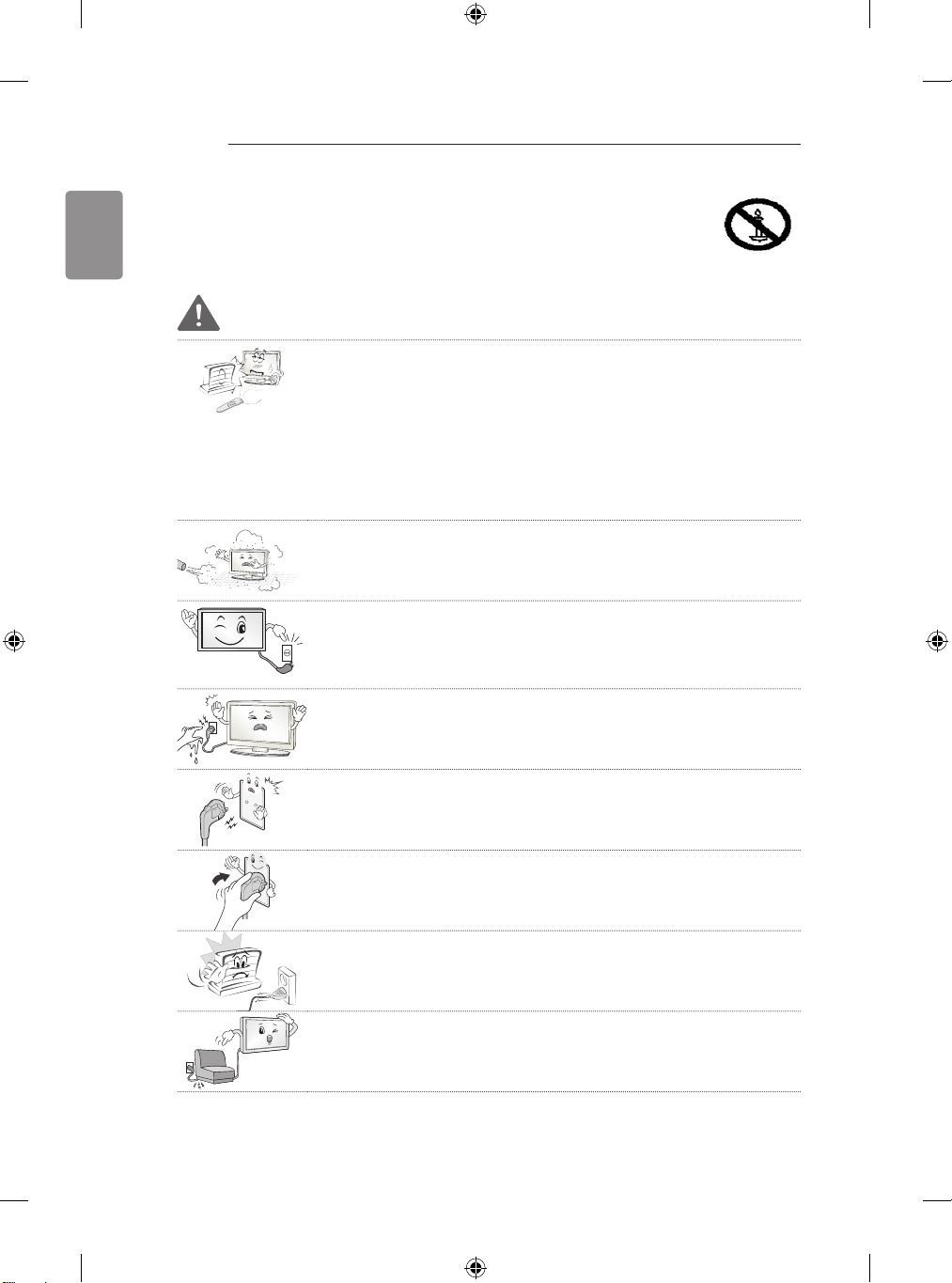
Do not place the TV and/or remote control in the following environments:
y
- A location exposed to direct sunlight
- An area with high humidity such as a bathroom
- Near any heat source such as stoves and other devices that produce
heat
- Near kitchen counters or humidifiers where they can easily be exposed
to steam or oil
- An area exposed to rain or wind
- Near containers of water such as vases
Otherwise, this may result in fire, electric shock, malfunction or product
deformation.
Do not place the product where it might be exposed to dust.
y
This may cause a fire hazard.
Mains Plug is the TV connecting/disconnecting device to AC mains electric
y
supply.This plug must remain readily attached and operable when TV is in
use.
Do not touch the power plug with wet hands. Additionally, if the cord pin is
y
wet or covered with dust, dry the power plug completely or wipe dust off.
You may be electrocuted due to excess moisture.
Make sure to connect Mains cable to compliant AC mains socket with
y
Grounded earth pin. (Except for devices which are not grounded on earth.)
Otherwise possibility you may be electrocuted or injured.
Insert power cable plug completely into wall socket otherwise if not secured
y
completely into socket, fire ignition may break out.
Ensure the power cord does not come into contact with hot objects such as
y
a heater.
This may cause a fire or an electric shock hazard.
Do not place a heavy object, or the product itself, on power cables.
y
Otherwise, this may result in fire or electric shock.
Page 7
SAFETY INSTRUCTIONS
Desiccant
5
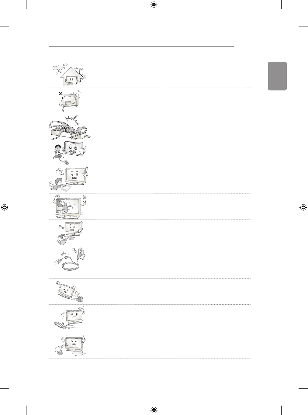
Bend antenna cable between inside and outside building to prevent rain
y
from flowing in.
This may cause water damaged inside the Product and could give an
electric shock.
When mounting TV onto wall make sure to neatly install and isolate cabling
y
from rear of TV as to not create possibility of electric shock /fire hazard.
Do not plug too many electrical devices into a single multiple electrical
y
outlet.
Otherwise, this may result in fire due to over-heating.
Do not drop the product or let it fall over when connecting external devices.
y
Otherwise, this may result in injury or damage to the product.
Keep the anti-moisture packing material or vinyl packing out of the reach of
y
children.
Anti-moisture material is harmful if swallowed. If swallowed by mistake,
force the patient to vomit and visit the nearest hospital. Additionally, vinyl
packing can cause suffocation. Keep it out of the reach of children.
Do not let your children climb or cling onto the TV.
y
Otherwise, the TV may fall over, which may cause serious injury.
Dispose of used batteries carefully to ensure that a small child does not
y
consume them.
Please seek Doctor- Medical Attention immediately if child consumes
batteries.
ENGLISH
Do not insert any metal objects/conductors (like a metal chopstick/cutlery/
y
screwdriver) between power cable plug and input Wall Socket while it is
connected to the input terminal on the wall. Additionally, do not touch the
power cable right after plugging into the wall input terminal. You may be
electrocuted.
(Depending on model)
Do not put or store inflammable substances near the product.
y
There is a danger of combustion/explosion or fire due to careless handling
of the inflammable substances.
Do not drop metallic objects such as coins, hair pins, chopsticks or wire into
y
the product, or inflammable objects such as paper and matches. Children
must pay particular attention.
Electrical shock, fire or injury can occur. If a foreign object is dropped into
the product, unplug the power cord and contact the service centre.
Do not spray water on the product or scrub with an inflammable substance
y
(thinner or benzene). Fire or electric shock accident can occur.
Page 8

6
SAFETY INSTRUCTIONS
ENGLISH
Do not allow any impact, shock or any objects to fall into the unit, and do
y
not drop anything onto the screen.
You may be injured or the product can be damaged.
Never touch this product or antenna during a thunder or lighting storm.
y
You may be electrocuted.
Never touch the wall outlet when there is leakage of gas, open the windows
y
and ventilate.
It may cause a fire or a burn by a spark.
Do not disassemble, repair or modify the product at your own discretion.
y
Fire or electric shock accident can occur.
Contact the service centre for check, calibration or repair.
If any of the following occur, unplug the product immediately and contact
y
your local service centre.
- The product has been impacted by shock
- The product has been damaged
- Foreign objects have entered the product
- The product produced smoke or a strange smell
This may result in fire or electric shock.
Unplug the TV from AC mains wall socket if you do not intend to use the TV
y
for a long period of time.
Accumulated dust can cause fire hazard and insulation deterioration can
cause electric leakage/shock/fire.
Apparatus shall not be exposed to dripping or splashing and no objects
y
filled with liquids, such as vases, shall be placed on the apparatus.
Do not install this product on a wall if it could be exposed to oil or oil mist.
y
This may damage the product and cause it to fall.
CAUTION
Install the product where no radio wave occurs.
y
There should be enough distance between an outside antenna and power
y
lines to keep the former from touching the latter even when the antenna
falls.
This may cause an electric shock.
Page 9
SAFETY INSTRUCTIONS
7
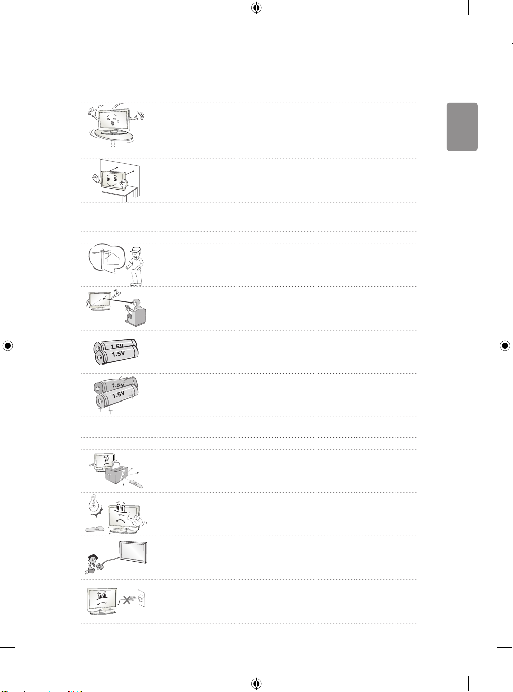
Do not install the product on places such as unstable shelves or inclined
y
surfaces. Also avoid places where there is vibration or where the product
cannot be fully supported.
Otherwise, the product may fall or flip over, which may cause injury or
damage to the product.
If you install the TV on a stand, you need to take actions to prevent the
y
product from overturning. Otherwise, the product may fall over, which may
cause injury.
If you intend to mount the product to a wall, attach VESA standard mounting interface (optional
y
parts) to the back of the product. When you install the set to use the wall mounting bracket (optional
parts), fix it carefully so as not to drop.
Only use the attachments / accessories specified by the manufacturer.
y
When installing the antenna, consult with a qualified service technician. If
y
not installed by a qualified technician, this may create a fire hazard or an
electric shock hazard.
We recommend that you maintain a distance of at least 2 to 7 times the
y
diagonal screen size when watching TV.
If you watch TV for a long period of time, this may cause blurred vision.
Only use the specified type of battery.
y
This could cause damage to the remote control.
Do not mix new batteries with old batteries.
y
This may cause the batteries to overheat and leak.
ENGLISH
Batteries should not be exposed to excessive heat. For example, keep away from direct Sunlight ,
y
open fireplace and electric heaters .
Do not place non-rechargeable batteries in charging device.
y
Make sure there are no objects between the remote control and its sensor.
y
Signal from Remote Control can be interrupted due to external/internal
y
lighting eg Sunlight, fluorescent lighting.
If this occurs turn off lighting or darken viewing area.
When connecting external devices such as video game consoles, make
y
sure the connecting cables are long enough.
Otherwise, the product may fall over, which may cause injury or damage
the product.
Do not turn the product On/Off by plugging-in or unplugging the power plug
y
to the wall outlet. (Do not use the power plug for switch.)
It may cause mechanical failure or could give an electric shock.
Page 10
8
SAFETY INSTRUCTIONS
ENGLISH
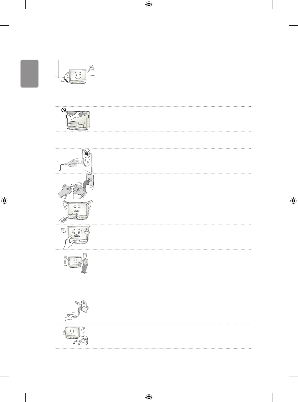
Please follow the installation instructions below to prevent the product from
y
overheating.
- The distance between the product and the wall should be more than
10 cm.
- Do not install the product in a place with no ventilation (e.g., on a
bookshelf or in a cupboard).
- Do not install the product on a carpet or cushion.
- Make sure the air vent is not blocked by a tablecloth or curtain.
Otherwise, this may result in fire.
Take care not to touch the ventilation openings when watching the TV for
y
long periods as the ventilation openings may become hot. This does not
affect the operation or performance of the product.
Periodically examine the cord of your appliance, and if its appearance indicates damage or
y
deterioration, unplug it, discontinue use of the appliance, and have the cord replaced with an
exact replacement part by an authorized servicer.
Prevent dust collecting on the power plug pins or outlet.
y
This may cause a fire hazard.
Protect the power cord from physical or mechanical abuse, such as being
y
twisted, kinked, pinched, closed in a door, or walked upon. Pay particular
attention to plugs, wall outlets, and the point where the cord exits the
appliance.
Do not press strongly upon the panel with a hand or sharp object such
y
as nail, pencil or pen, or make a scratch on it, as it may cause damage to
screen.
Avoid touching the screen or holding your finger(s) against it for long
y
periods of time. Doing so may produce some temporary or permanent
distortion/damage to screen.
When cleaning the product and its components, unplug the power first and
y
wipe it with a soft cloth. Applying excessive force may cause scratches or
discolouration. Do not spray with water or wipe with a wet cloth. Never use
glass cleaner, car or industrial shiner, abrasives or wax, benzene, alcohol
etc., which can damage the product and its panel.
Otherwise, this may result in fire, electric shock or product damage
(deformation, corrosion or breakage).
As long as this unit is connected to the AC wall outlet, it is not disconnected from the AC power
y
source even if you turn off this unit by SWITCH.
When unplugging the cable, grab the plug and unplug it, by pulling at the
y
plug.
Don’t pull at the cord to unplug the power cord from the power board, as
this could be hazardous.
When moving the product, make sure you turn the power off first. Then,
y
unplug the power cables, antenna cables and all connecting cables.
The TV set or power cord may be damaged, which may create a fire hazard
or cause electric shock.
Page 11
SAFETY INSTRUCTIONS
9
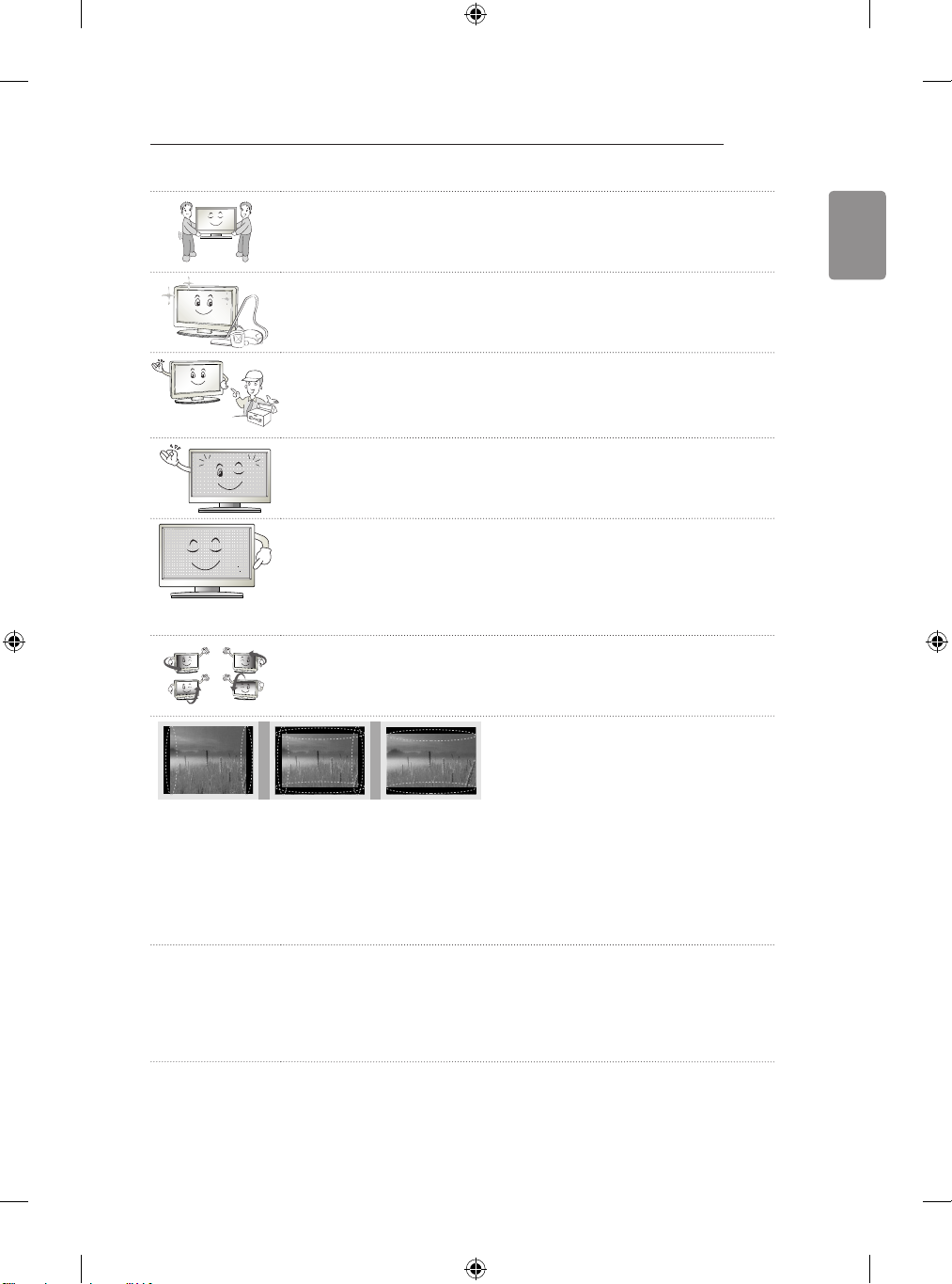
When moving or unpacking the product, work in pairs because the product
y
is heavy.
Otherwise, this may result in injury.
Contact the service centre once a year to clean the internal parts of the
y
product.
Accumulated dust can cause mechanical failure.
Refer all servicing to qualified service personnel. Servicing is required when
y
the apparatus has been damaged in any way, such as power supply cord
or plug is damaged, liquid has been spilled or objects have fallen into the
apparatus, the apparatus has been exposed to rain or moisture, does not
operate normally, or has been dropped.
If the product feels cold to the touch, there may be a small “flicker” when it
y
is turned on. This is normal, there is nothing wrong with product.
The panel is a high technology display product with resolution of two million
y
to six million pixels. You may see tiny black dots and/or brightly coloured
dots (red, blue or green) at a size of 1 ppm on the panel. This does not
indicate a malfunction and does not affect the performance and reliability of
the product.
This phenomenon also occurs in third-party products and is not subject to
exchange or refund.
You may find different brightness and color of the panel depending on your
y
viewing position(left/right/top/down).
This phenomenon occurs due to the characteristic of the panel. It is not
related with the product performance, and it is not malfunction.
ENGLISH
Displaying a still image (e.g., broadcasting channel logo, on-screen menu, scene from a video
y
game) for a prolonged time may cause damage to the screen, resulting in retention of the image,
which is known as image sticking. The warranty does not cover the product for image sticking.
Avoid displaying a fixed image on your television’s screen for a prolonged period (2 or more hours
for LCD, 1 or more hours for Plasma).
Also, if you watch the TV at a ratio of 4:3 for a long time, image sticking may occur on the borders
of the panel.
This phenomenon also occurs in third-party products and is not subject to exchange or refund.
Generated Sound
y
“Cracking” noise: A cracking noise that occurs when watching or turning off the TV is generated by
plastic thermal contraction due to tempera-ture and humidity. This noise is common for products
where thermal deformation is required. Electrical circuit humming/panel buzzing: A low level noise
is generated from a high-speed switching circuit, which supplies a large amount of current to
operate a product. It varies depending on the product.
This generated sound does not affect the performance and reliability of the product.
Page 12

10
SAFETY INSTRUCTIONS
ENGLISH
Viewing 3D Imaging (Only 3D models)
WARNING
Viewing Environment
Viewing Time
y
- When watching 3D contents, take 5 - 15 minute breaks every hour. Viewing 3D contents for a
long period of time may cause headache, dizziness, fatigue or eye strain.
Those that have a photosensitive seizure or chronic illness
Some users may experience a seizure or other abnormal symptoms when they are exposed to a
y
ashing light or particular pattern from 3D contents.
Do not watch 3D videos if you feel nausea, are pregnant and/ or have a chronic illness such as
y
epilepsy, cardiac disorder, or blood pressure disease, etc.
y3D Contents are not recommended to those who suffer from stereo blindness or stereo anomaly.
Double images or discomfort in viewing may be experienced.
If you have strabismus (cross-eyed), amblyopia (weak eyesight) or astigmatism, you may have trouble
y
sensing depth and easily feel fatigue due to double images. It is advised to take frequent breaks than
the average adult.
yIf your eyesight varies between your right and left eye, revise your eyesight prior to watching 3D
contents.
Symptoms which require discontinuation or refraining from watching 3D contents
Do not watch 3D contents when you feel fatigue from lack of sleep, overwork or drinking.
y
When these symptoms are experienced, stop using/watching 3D contents and get enough rest until
y
the symptom subsides.
- Consult your doctor when the symptoms persist. Symptoms may include headache, eyeball pain,
dizziness, nausea, palpitation, blurriness, discomfort, double image, visual inconvenience or
fatigue.
Page 13

SAFETY INSTRUCTIONS
CAUTION
Viewing Environment
y Viewing Distance
- Maintain a distance of at least twice the screen diagonal length when watching 3D contents. If
you feel discomfort in viewing 3D contents, move further away from the TV.
Viewing Age
yInfants/Children
- Usage/ Viewing 3D contents for children under the age of 6 are prohibited.
- Children under the age of 10 may overreact and become overly excited because their vision is in
development (for example: trying to touch the screen or trying to jump into it. Special monitoring
and extra attention is required for children watching 3D contents.
- Children have greater binocular disparity of 3D presentations than adults because the distance
between the eyes is shorter than that of adults. Therefore they will perceive more stereoscopic
depth compared to adults for the same 3D image.
Teenagers
y
- Teenagers under the age of 19 may react with sensitivity due to stimulation from light in 3D
contents. Advise them to refrain from watching 3D contens for a long time when they are tired.
Elderly
y
- The elderly may perceive less 3D effect compared to the young. Do not sit closer to the TV than
the recommended distance.
11
ENGLISH
Cautions when using the 3D glasses
y Make sure to use LG 3D glasses. Otherwise, you may not be able to view 3D videos properly.
y Do not use 3D glasses instead of your normal glasses, sunglasses or protective goggles.
y Using modied 3D glasses may cause eye strain or image distortion.
y Do not keep your 3D glasses in extremely high or low temperatures. It will cause deformation.
y The 3D glasses are fragile and are easily scratched. Always use a soft, clean piece of cloth when
wiping the lenses. Do not scratch the lenses of the 3D glasses with sharp objects or clean/wipe them
with chemicals.
Page 14

12
<
<
INSTALLATION PROCEDURE / ASSEMBLING AND PREPARING
ENGLISH
NOTE
Image shown may differ from your TV.
y
Your TV’s OSD (On Screen Display) may differ slightly from that shown in this manual.
y
The available menus and options may differ from the input source or product model that you are
y
using.
New features may be added to this TV in the future.
y
The TV can be placed in standby mode in order to reduce the power consumption. And the TV
y
should be turned off if it will not be watched for some time, as this will reduce energy consumption.
The energy consumed during use can be significantly reduced if the level of brightness of the
y
picture is reduced, and this will reduce the overall running cost.
INSTALLATION PROCEDURE
1 Open the package and make sure all the accessories are included.
2 Attach the stand to the TV set.
3 Connect an external device to the TV set.
4 Make sure the network connection is available.
You can use the TV network functions only when the network connection is made.
* If the TV is turned on for the rst time after it was shipped from the factory, initialization of the TV may
take up to one minute.
ASSEMBLING AND PREPARING
Unpacking
Check your product box for the following items. If there are any missing accessories, contact the local
dealer where you purchased your product. The illustrations in this manual may differ from the actual
product and item.
CAUTION
Do not use any unapproved items to ensure the safety and product life span.
y
Any damage or injuries caused by using unapproved items are not covered by the warranty.
y
Some models have a thin film attached on to the screen and this must not be removed.
y
NOTE
The items supplied with your product may vary depending on the model.
y
Product specifications or contents of this manual may be changed without prior notice due to
y
upgrade of product functions.
For an optimal connection, HDMI cables and USB devices should have bezels less than 10 mm
y
thick and 18 mm width. Use an extension cable that supports USB 2.0 if the USB cable or USB
memory stick does not fit into your TV’s USB port.
B
A
B
*A
10 mm
=
18 mm
*B
A
=
Page 15
ENERGY
SAVING
1 2 3
4 5 6
7 809
LIST
MENU
BACK
ASSEMBLING AND PREPARING
13
ENGLISH
AV MODE
INPUT
TV
FLASHBK
MARK
FAV
P
A
G
3D
CHVOL
E
MUTE
INFO
Q.MENU
ENTER
EXIT
L/R SELECT
FREEZE
RATIO
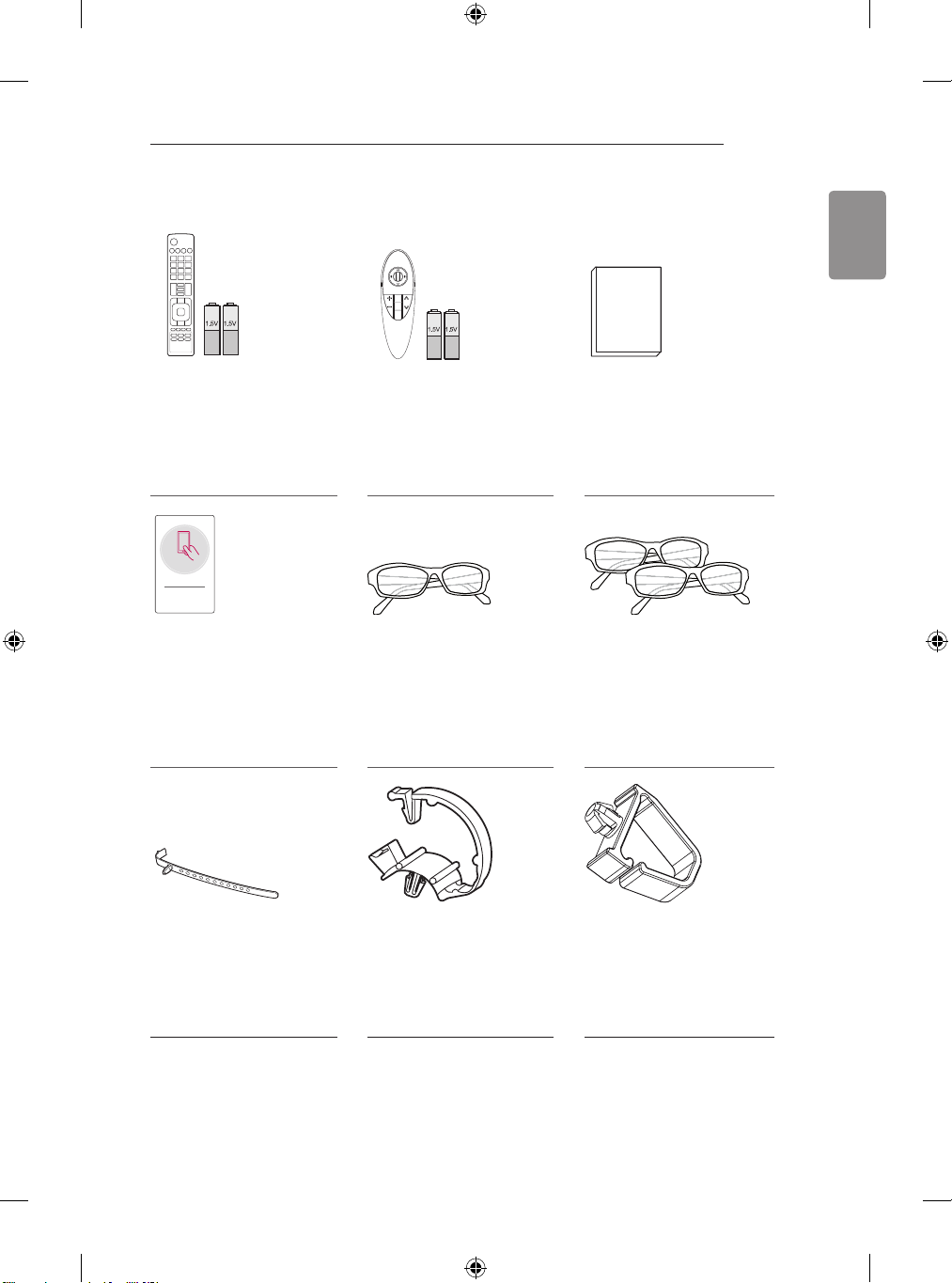
Remote Control, Batteries
(AAA)
(Depending on model)
The remote control will not be
included for all sales market.
(See p. 42, 43)
Tag On
Magic Remote, Batteries
(AA)
(Only LB67**, LB68**,
LB69**, LB72**, LB73**,
LB86**, LB87**)
(See p. 44)
Tag on Cinema 3D Glasses
The number of 3D glasses
may differ depending on the
model or country.
(Only LB65**, LB67**,
LB68**, LB69**, LB72**,
LB73**, LB86**, LB87**)
Cable Holder
(Depending on model)
(See p. 30, 31)
Cable Managements
2EA
(Only LB63**, LB65**-ZA/
ZK/ZH/ZL, LB67**, LB68**,
LB69**, LB72**, LB73**-ZA)
(See p. 30, 31)
Owner’s Manual
Dual Play Glasses
(Depending on model)
Cable Managements
2EA
(Only LB73**-ZD/ZE)
(See p. 31)
Page 16
ENGLISH
14
ASSEMBLING AND PREPARING
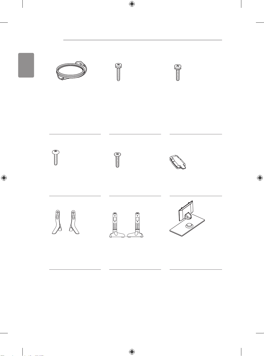
Power Cord Stand Screws
2EA, M4 x L20
(Only 32/39LB65**-ZE/ZN)
4EA, M4 x L20
(Only 32LB65**-ZA/ZK)
(See p. 21, 22, 23)
Stand Screws
4EA, M4 x L20
(Only LB65**-ZE/ZN)
(See p. 22, 23)
Stand Screws
4EA, M4 x L10
(Only LB73**-ZD/ZE)
(See p. 24)
Stand Screws
4EA, M4 x L14
(Only LB63**, 39LB65**-ZA/
ZK, 42/47/50/55/60/70LB65**,
LB67**, LB68**, LB69**,
LB72**, LB73**)
8EA, M4 x L14
(Only LB86**, LB87**)
(See p. 21, 22, 24, 25, 26, 27)
Rubbers
2EA
(Only LB65**-ZE/ZN)
(See p. 26)
Stand Bases
(Only LB63**-ZA,
32/39/42/47/50/55LB65**ZA)
(See p. 21)
Stand Bases
(Only LB63**-ZL, LB65**-ZK)
(See p. 22)
Stand Base/Stand Body
(Only LB65**-ZE/ZN)
(See p. 22, 23)
Page 17

ASSEMBLING AND PREPARING
15
ENGLISH
Stand Assys
(Stand Base/Stand Body)
(Only 70LB65**-ZA, LB67**,
LB68**, LB69**, LB72**,
LB73**-ZA)
(See p. 21)
Stand Assys
(Only LB86**, LB87**)
(See p. 25)
Screw Covers
(Only LB86**, LB87**)
(See p. 25, 27)
Stand Front
(Only LB73**-ZD/ZE)
(See p. 24)
Sound Bar
(Only LB86**, LB87**)
(See p. 25, 26)
Component Gender
Cable
(Only LB86**, LB87**)
(See p. 37)
Stand Supporters
(Only LB73**-ZD/ZE)
(See p. 24)
Sound Bar Supporters
(Only LB86**, LB87**)
(See p. 26)
Composite Gender
Cable
(Only LB86**, LB87**)
(See p. 37, 38)
Scart Gender Cable
(Only LB86**, LB87**)
(See p. 41)
Wall Mount Spacers
2EA
(Only 42LB63**, 42LB65**)
(See p. 30)
Page 18

16
ASSEMBLING AND PREPARING
ENGLISH
Separate purchase
Separate purchase items can be changed or modied for quality improvement without any notication.
Contact your dealer to buy these items.
These devices only work with certain models.
AG-F***DP
Dual Play Glasses
AN-VC5**
Video Call Camera LG Audio Device Tag on
Compatibility
AG-F***DP
Dual Play Glasses
AG-F***
Cinema 3D Glasses
AN-MR500
Magic Remote
AN-VC5**
Video Call Camera
LG Audio Device
Tag On
The model name or design may be changed depending on the upgrade of product functions,
manufacturer’s circumstances or policies.
AG-F***
Cinema 3D Glasses
LB63** LB65**
• • •
• • •
• • • •
• • •
• • • •
• • • •
AN-MR500
Magic Remote
LB67**, LB68**,
LB69**, LB72**,
LB73**, LB86**
LB87**
Page 19

ASSEMBLING AND PREPARING
17
Parts and buttons
A type : LB63**-ZA, LB65**-ZA B type : LB63**-ZL, LB65**-ZK
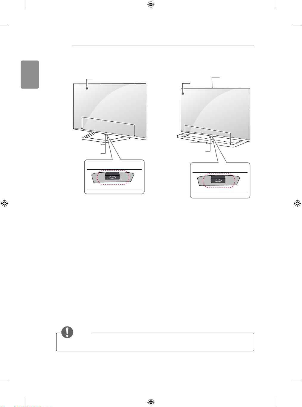
Screen
Speakers
Remote control and
Intelligent1 sensors
Power Indicator
Joystick Button
2
Remote control and
Intelligent1 sensors
Power Indicator
C type : LB65**-ZE/ZN D type : LB67**, LB68**, LB69**, LB72**,
Screen
Screen
Speakers
LB73**-ZA
Screen
Joystick Button
2
ENGLISH
Speakers
Remote control and
Intelligent1 sensors
Power Indicator
Joystick Button
Speakers
Remote control and
Intelligent1 sensors
Power Indicator
2
Joystick Button
2
Page 20
18
ASSEMBLING AND PREPARING
ENGLISH
Screen
Remote control and
Intelligent1 sensors
Power Indicator
Speakers
Joystick Button
F type : LB86**, LB87**E type : LB73**-ZE/ZD
Built-in Camera
Screen
(Only LB87**)
Speakers
LG Logo light
Remote control and
Intelligent1 sensors
2
Joystick Button
2
1 Intelligent sensor - Adjusts the image quality and brightness based on the surrounding environment.
2 Joystick Button - This button is located below the TV screen.
NOTE
You can set the LG Logo Light or Power Indicator Light to on or off by selecting OPTION in the
y
main menus. (Depending on model)
Page 21
ASSEMBLING AND PREPARING
19
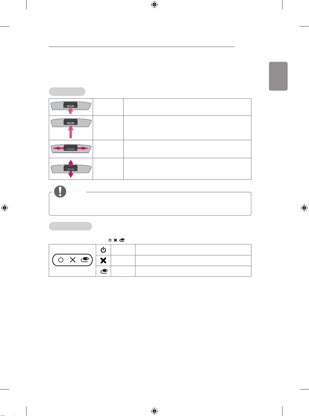
Using the Joystick button
You can simply operate the TV functions, pressing or moving the joystick button up, down, left or right.
Basic Functions
Power On
Power Off
Volume
Control
Programmes
Control
NOTE
When your finger over the joystick button and push it to the up, down, left or right, be careful not to
y
press the joystick button. If you press the joystick button first, you can not adjust the volume level
and saved programmes.
Adjusting the Menu
When the TV is turned on, press the joystick button one time.
You can adjust the Menu items(
When the TV is turned off, place your finger on the joystick button
and press it once and release it.
When the TV is turned on, place your finger on the joystick
button and press it once for a few seconds and release it.
If you place your finger over the joystick button and move it left or
right, you can adjust the volume level you want.
If you place your finger over the joystick button and move it up or
down, you can scrolls through the saved programmes you want.
, , )moving the joystick button up, down, left or right.
TV OFF Turns the power off.
CLOSE Clears on-screen displays and returns to TV viewing.
ENGLISH
INPUT Changes the input source.
Page 22
ENGLISH
20
ASSEMBLING AND PREPARING
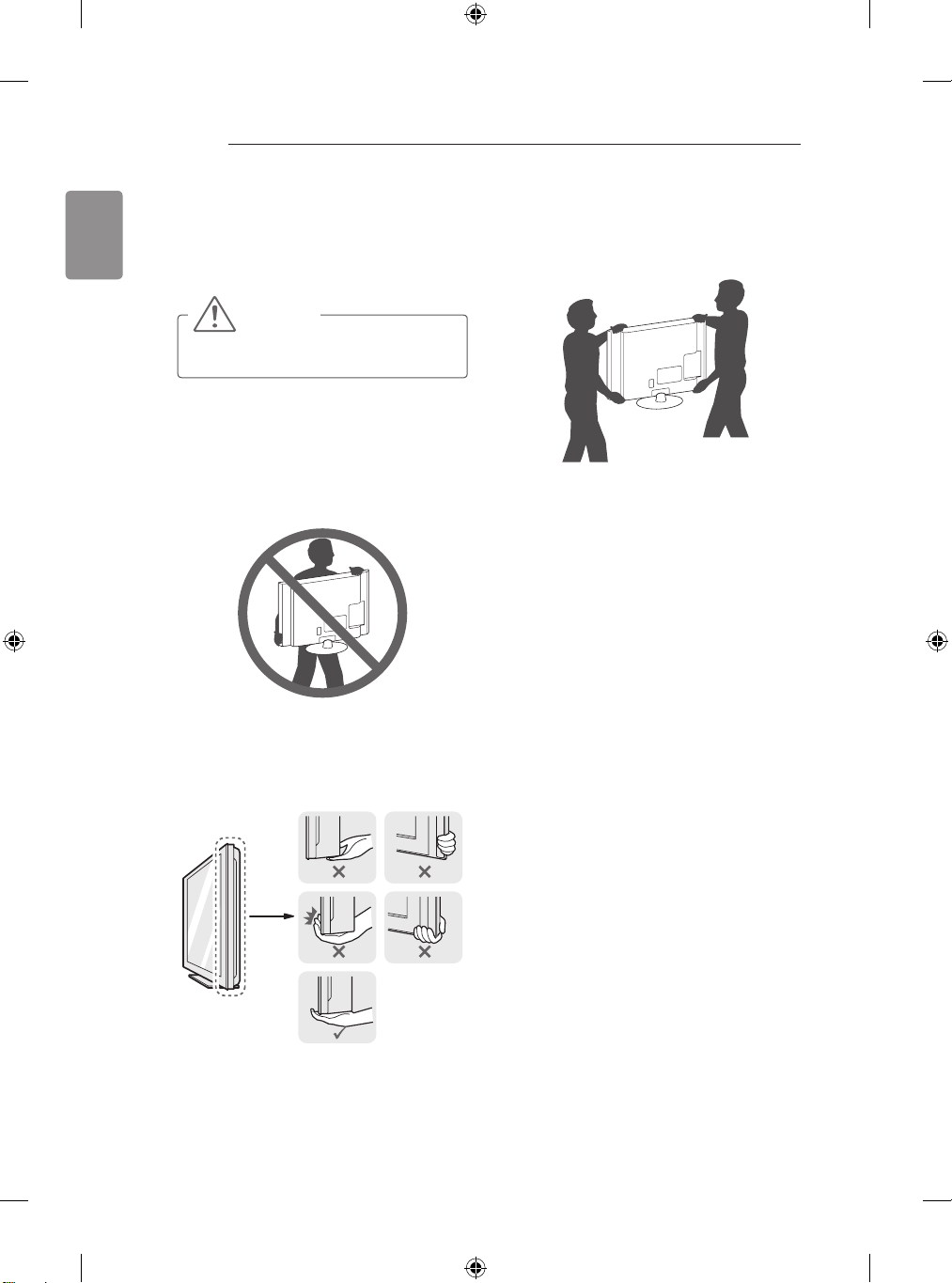
Lifting and moving the TV
Please note the following advice to prevent the
TV from being scratched or damaged and for safe
transportation regardless of its type and size.
CAUTION
Avoid touching the screen at all times, as
y
this may result in damage to the screen.
It is recommended to move the TV in the
y
box or packing material that the TV originally
came in.
Before moving or lifting the TV, disconnect
y
the power cord and all cables.
When holding the TV, the screen should face
y
away from you to avoid damage.
When transporting a large TV, there should
y
be at least 2 people.
When transporting the TV by hand, hold the
y
TV as shown in the following illustration.
When transporting the TV, do not expose the
y
TV to jolts or excessive vibration.
When transporting the TV, keep the TV
y
upright, never turn the TV on its side or tilt
towards the left or right.
Do not apply excessive pressure to cause
y
exing /bending of frame chassis as it may
damage screen.
When handling the TV, be careful not to
y
damage the protruding joystick button.
Hold the top and bottom of the TV frame
y
rmly. Make sure not to hold the transparent
part, speaker, or speaker grill area.
Page 23
ASSEMBLING AND PREPARING
1
2
1
2
21
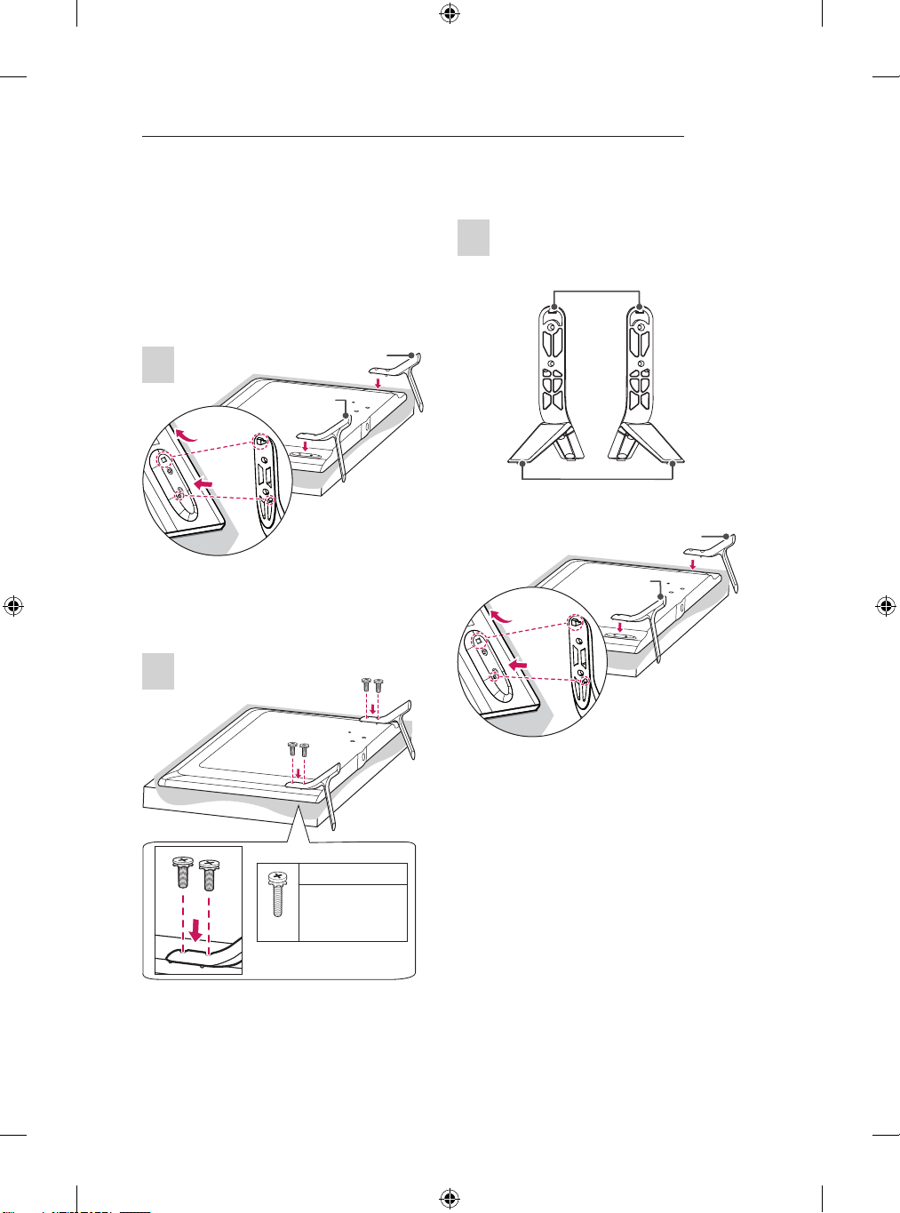
Setting up the TV
Image shown may differ from your TV.
Attaching the stand
LB63**-ZA, 32/39/42/47/50/55LB65**-ZA
A stand base
1
B stand base
1 Attach the stand to the TV using the upper
mounting hole on the back of the TV.
2 Attach the stand to the TV using the lower
connection on the back of the TV.
2
70LB65**-ZA, LB67**, LB68**, LB69**, LB72**,
LB73**-ZA
1
Stand Body
Stand Base
A stand Assy
B stand Assy
1 Attach the stand to the TV using the upper
mounting hole on the back of the TV.
2 Attach the stand to the TV using the lower
connection on the back of the TV.
M4 x L14
M4 x L20
(Only 32LB65**ZA)
4EA
Page 24
22
2
1
2
1
ASSEMBLING AND PREPARING
2
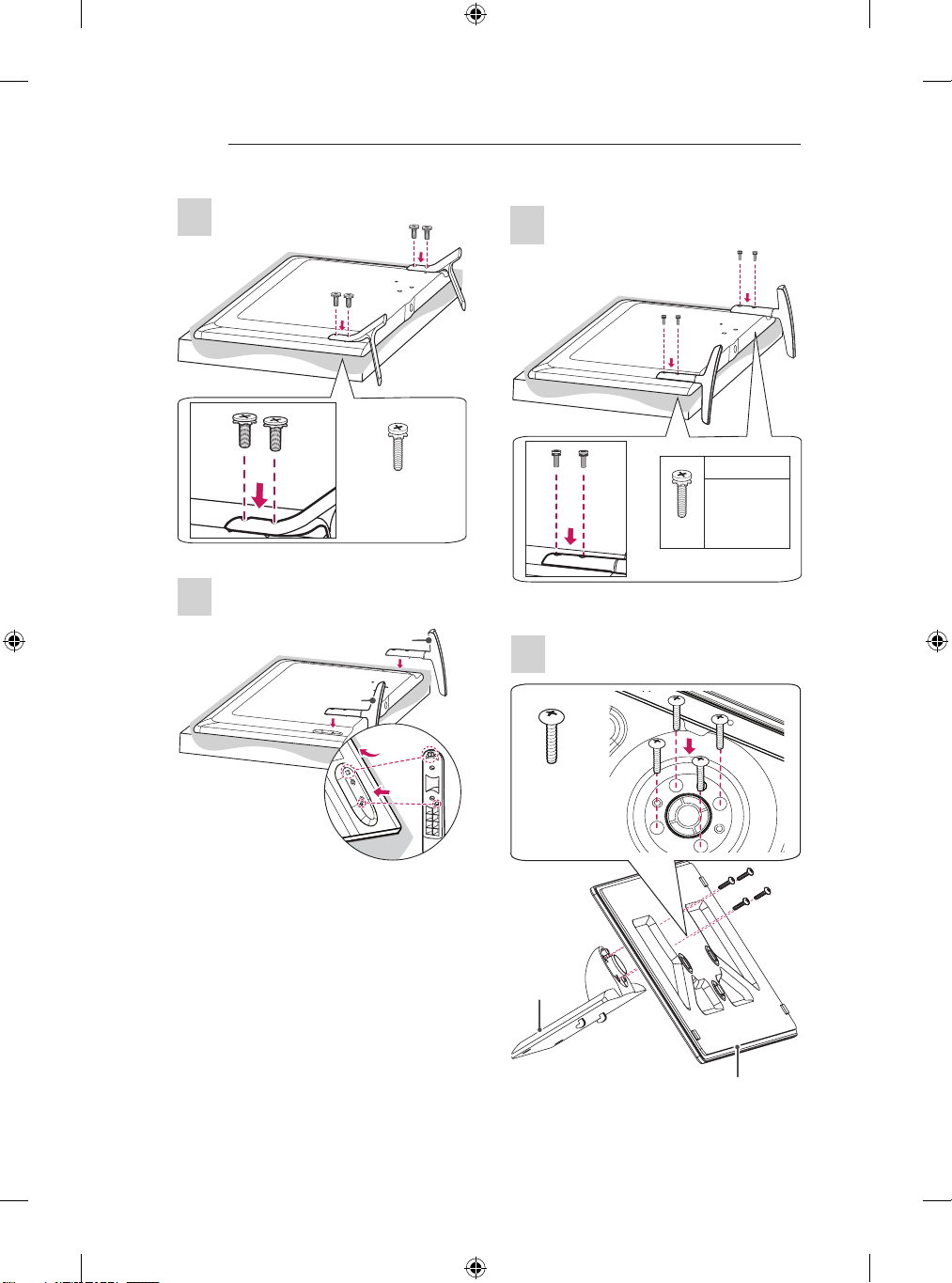
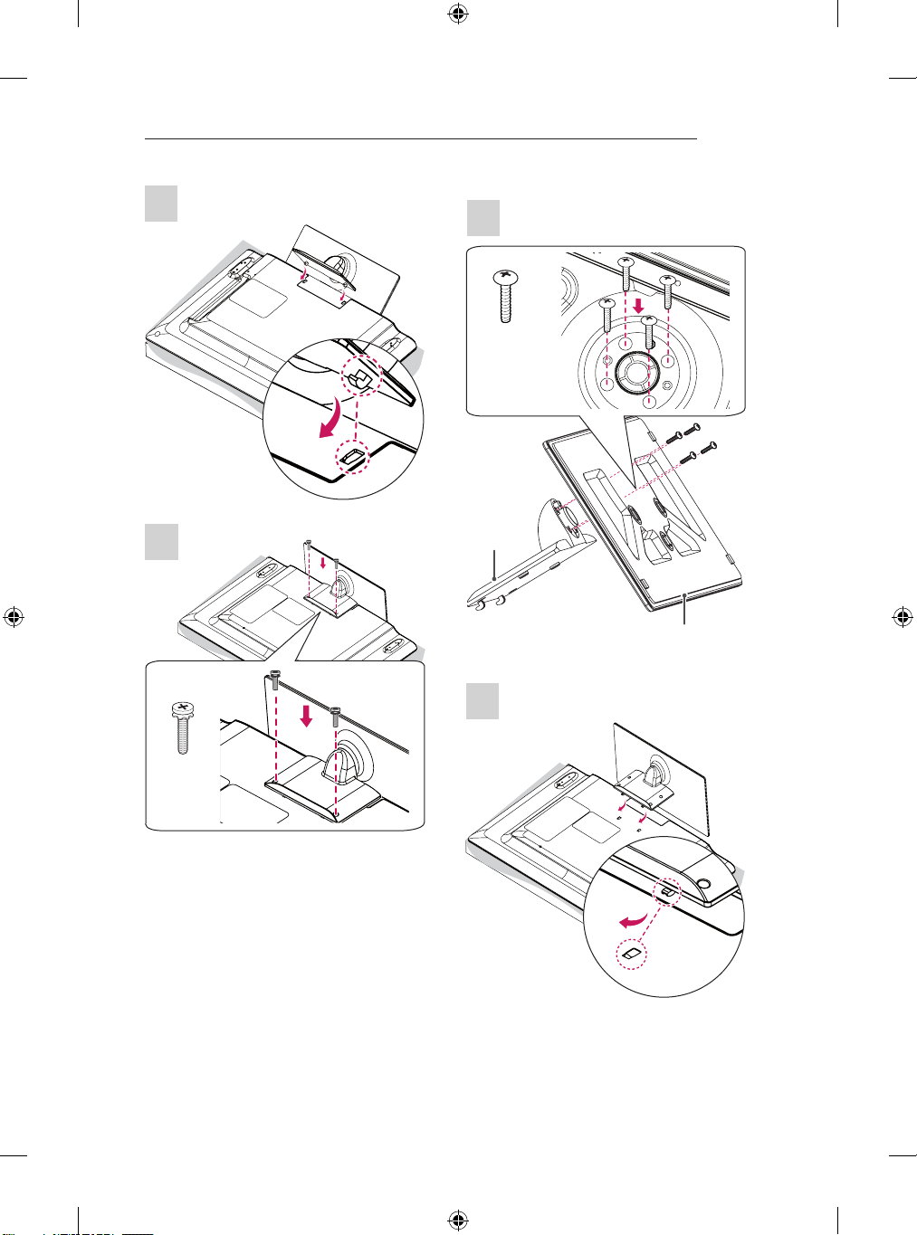
LB63**-ZL, LB65**-ZK
1
B stand base
4EA
M4 x L14
A stand base
2
32/39LB65**-ZE/ZN
1
4EA
M4 x L14
M4 x L20
(Only
32LB65**ZK)
4EA
M4 x L20
1
1 Attach the stand to the TV using the upper
mounting hole on the back of the TV.
2 Attach the stand to the TV using the lower
connection on the back of the TV.
Stand Body
Stand Base
Page 25
ASSEMBLING AND PREPARING
23
2
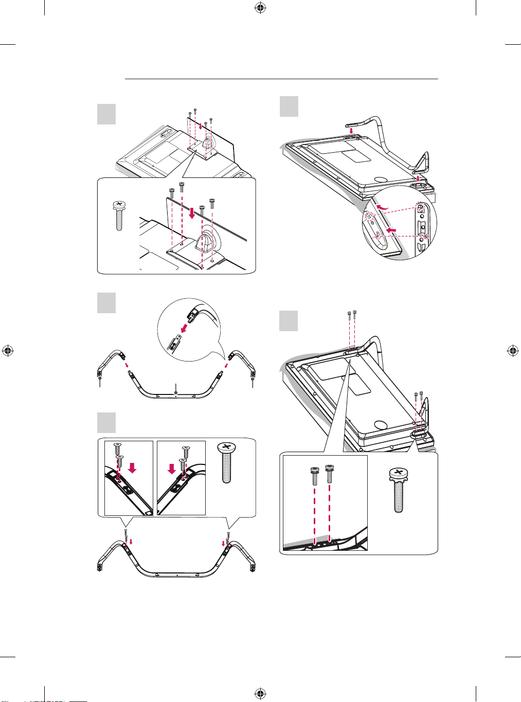
42/47/50/55/60LB65**-ZE/ZN
1
4EA
M4 x L20
1
3
Stand Body
Stand Base
2
2EA
M4 x L20
Page 26
24
1
2
ASSEMBLING AND PREPARING
3
4EA
M4 x L14
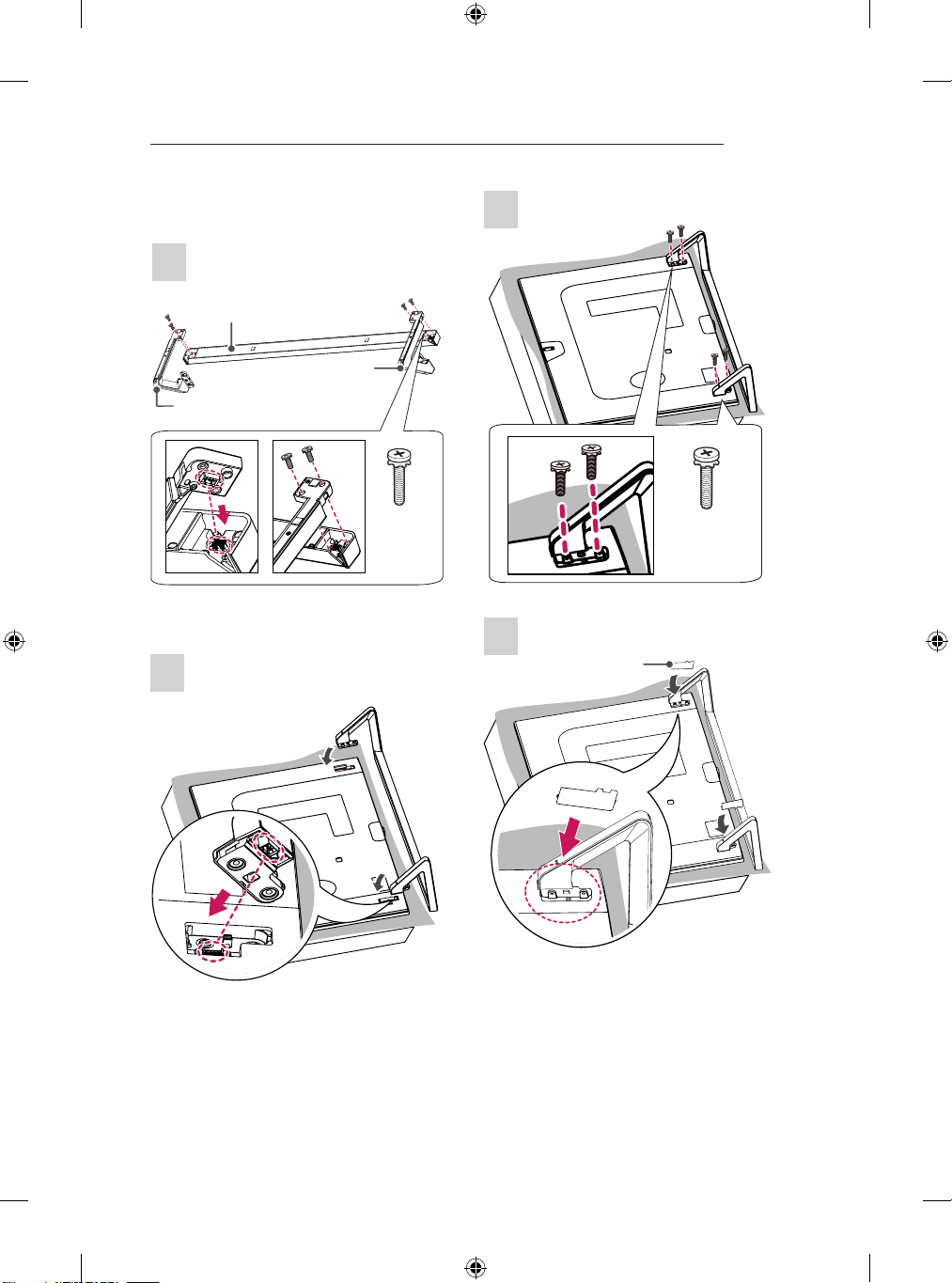
LB73**-ZD/ZE
1
B Stand
Supporter
Stand Front
A Stand
Supporter
3
1 Attach the stand to the TV using the upper
mounting hole on the back of the TV.
2 Attach the stand to the TV using the lower
connection on the back of the TV.
4
2
4EA
M4 x L10
4EA
M4 x L14
Page 27
ASSEMBLING AND PREPARING
25
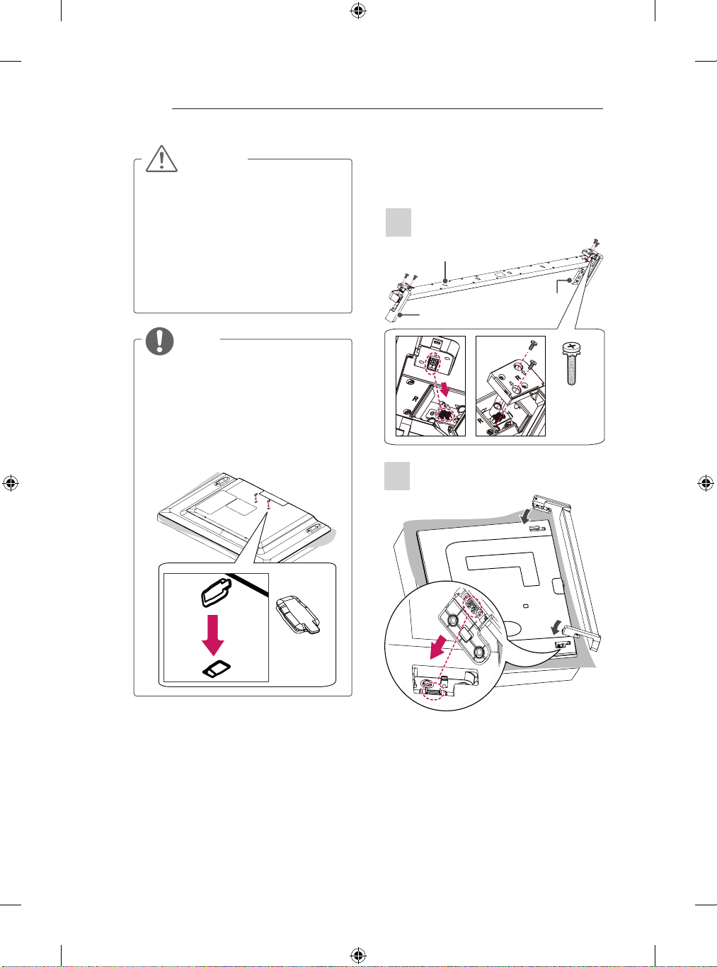
LB86**, LB87**
1
Sound Bar
Stand Assy Left
2
Stand Assy Right
4EA
M4 x L14
3
4EA
M4 x L14
4
Screw Cover
Page 28
26
ASSEMBLING AND PREPARING
CAUTION
When attaching the stand to the TV
y
set, place the screen facing down on a
cushioned table or flat surface to protect
the screen from scratches.
Make sure that the screws are inserted
y
correctly and fastened securely. (If they
are not fastened securely enough, the TV
may tilt forward after being installed.)
Do not use too much force and over
tighten the screws; otherwise screw may
be damaged and not tighten correctly.
NOTE
Remove the stand before installing the
y
TV on a wall mount by performing the
stand attachment in reverse.
Screw Cover will protect the opening from
y
accumulating dust and dirty.
Rubber will protect the opening from
y
accumulating dust and dirt. When
installing the wall mounting bracket, use
the Rubber. (Only LB65**-ZE/ZN)
Attaching the Sound Bar Supporter
(In case of mounting on a wall)
LB86**, LB87**
1
Sound Bar
Sound Bar Supporter Right
Sound Bar Supporter Left
4EA
M4 x L14
2
Rubber
Page 29
ASSEMBLING AND PREPARING
27
3
CAUTION
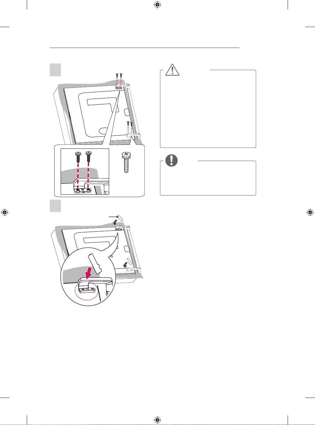
When attaching the sound bar supporter
y
to the TV set, place the screen facing
down on a cushioned table or flat surface
to protect the screen from scratches.
Make sure that the screws are inserted
y
correctly and fastened securely. (If they
are not fastened securely enough, the TV
may tilt forward after being installed.)
Do not use too much force and over
tighten the screws; otherwise screw may
be damaged and not tighten correctly.
The sound bar supporter only uses for
y
wall mounting.
NOTE
Remove the sound bar supporter before
y
4EA
M4 x L14
installing the stand by performing the
stand attachment in reverse.
The Screw Cover will protect the opening
y
from accumulating dust and dirty.
4
Screw Cover
Page 30
28
ASSEMBLING AND PREPARING
ENGLISH
Mounting on a table
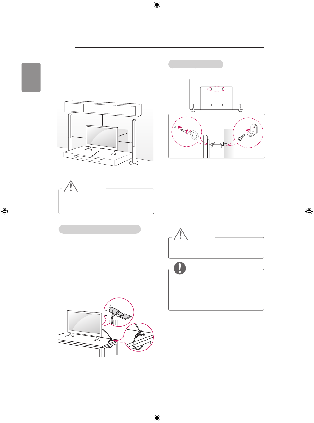
1 Lift and tilt the TV into its upright position on a
table.
- Leave a 10 cm (minimum) space from
the wall for proper ventilation.
10 cm
10 cm
10 cm
2 Connect the power cord to a wall outlet.
CAUTION
Do not place the TV near or on sources
y
of heat, as this may result in fire or other
damage.
Using the Kensington security system
(This not available for all models.)
Image shown may differ from your TV.
y
The Kensington security system connector is
located at the rear of the TV. For more information
of installation and using, refer to the manual
provided with the Kensington security system or
http://www.kensington.com.
visit
Connect the Kensington security system cable
between the TV and a table.
10 cm
10 cm
Securing the TV to a wall
(This feature is not available for all models.)
1 Insert and tighten the eye-bolts, or TV brackets
and bolts on the back of the TV.
- If there are bolts inserted at the eyebolts position, remove the bolts first.
2 Mount the wall brackets with the bolts to the
wall.
Match the location of the wall bracket and the
eye-bolts on the rear of the TV.
3 Connect the eye-bolts and wall brackets tightly
with a sturdy rope.
Make sure to keep the rope horizontal with the
at surface.
CAUTION
Make sure that children do not climb on
y
or hang on the TV.
NOTE
Use a platform or cabinet that is strong
y
and large enough to support the TV
securely.
Brackets, bolts and ropes are not
y
provided. You can obtain additional
accessories from your local dealer.
Page 31
ASSEMBLING AND PREPARING
29
Mounting on a wall
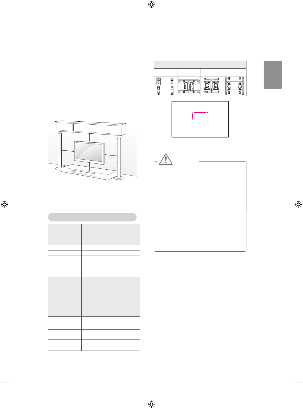
Attach an optional wall mount bracket at the rear
of the TV carefully and install the wall mount
bracket on a solid wall perpendicular to the
oor. When you attach the TV to other building
materials, please contact qualied personnel.
LG recommends that wall mounting be performed
by a qualied professional installer.
10 cm
10 cm
Make sure to use screws and wall mount
bracket that meet the VESA standard. Standard
dimensions for the wall mount kits are described
in the following table.
Separate purchase(Wall Mounting Bracket)
Model
VESA (A x B) 200 x 200 400 x 400
Standard screw M6 M6
Number of
screws
Wall mount
bracket
Model
VESA (A x B) 400 x 400 600 x 400
Standard screw M6 M6
Number of
screws
Wall mount
bracket
32/39LB65**
4 4
LSW240B
MSW240
60LB65**
42/47/50/55LB67**
42/47/55/60/65LB68**
42/47/55LB69**
42/47/55/60/65LB72**
42/47/55/60/65LB73**
60LB86**
60LB87**
4 4
LSW440B LSW640B
10 cm
10 cm
42/47/55LB63**
42/47/50/55LB65**
49/55LB86**
49/55LB87**
LSW440B
MSW240
70LB65**
Wall mount bracket
MSW240 LSW240B LSW440B LSW640B
A
B
CAUTION
Disconnect the power first, and then
y
move or install the TV. Otherwise electric
shock may occur.
If you install the TV on a ceiling or slanted
y
wall, it may fall and result in severe injury.
Use an authorised LG wall mount and
contact the local dealer or qualified
personnel.
Do not over tighten the screws as this
y
may cause damage to the TV and void
your warranty.
yUse the screws and wall mounts that
meet the VESA standard. Any damages
or injuries by misuse or using an
improper accessory are not covered by
the warranty.
ENGLISH
Page 32
ENGLISH
30
ASSEMBLING AND PREPARING
NOTE
Use the screws that are listed on the
y
VESA standard screw specifications.
The wall mount kit includes an installation
y
manual and necessary parts.
The wall mount bracket is not provided.
y
You can obtain additional accessories
from your local dealer.
The length of screws may differ
y
depending on the wall mount. Make sure
to use the proper length.
For more information, refer to the manual
y
supplied with the wall mount.
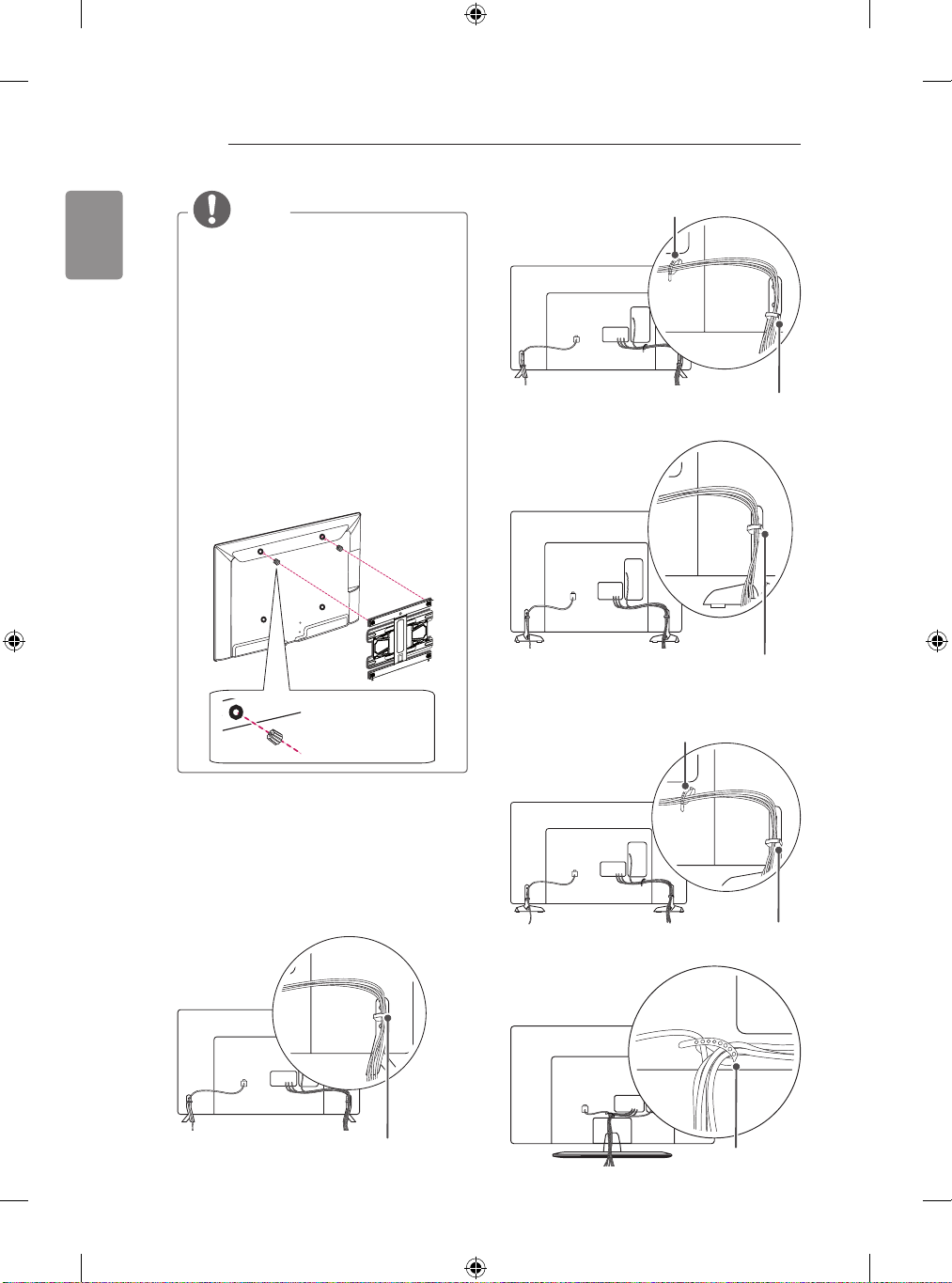
When attaching a wall mounting bracket
y
to the TV, insert the wall mount spacers
into the TV wall mount holes to adjust the
vertical angle of the TV. (Only 42LB63**,
42LB65**)
Wall Mount Spacer
(Only LB63**-ZA, 39/42/47/50/55/60LB65**-ZA,
LB67**, LB68**, LB69**, LB72**, LB73**-ZA)
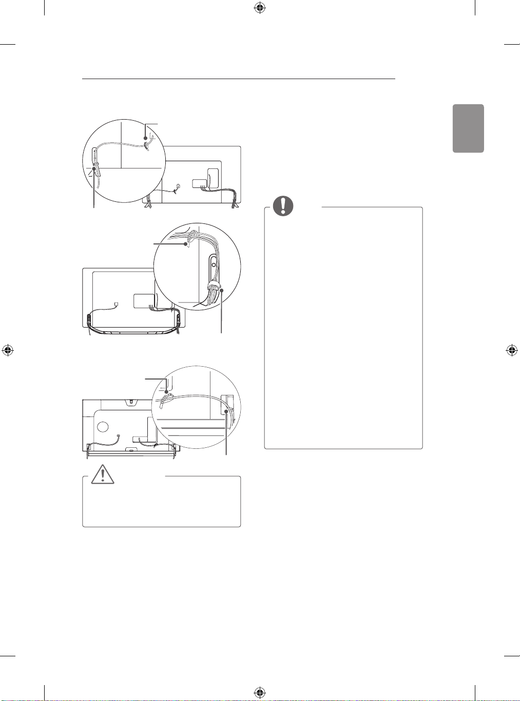
Cable Holder
Cable Management
(Only 32LB65**-ZK)
Cable Management
(Only LB63**-ZL, 39/42/47/50/55/60/70LB65**ZK/ZL)
Cable Holder
Tidying cables
Image shown may differ from your TV.
1 Gather and bind the cables with the cable
holder. (Depending on model)
2 Fix the Cable Management rmly to the TV.
(Only 32LB65**-ZA)
Cable Management
Cable Management
(Only LB65**-ZE/ZN)
Cable Holder
Page 33
ASSEMBLING AND PREPARING
31
(Only 70LB65**)
Cable Management
(Only LB73**-ZD/ZE)
Cable Holder
(Only LB86**, LB87**)
Cable Holder
Cable Holder
Cable Management
Using Built-in Camera
(Only LB87**)
You can make a Skype video call or use the
motion recognition function using the built-in
camera of the TV.
This TV does not support the use of an external
camera.
NOTE
Before using the built-in camera, you
y
must recognize the fact that you are
legally responsible for the use or misuse
of the camera by the relevant national
laws including the criminal law.
The relevant laws include the Personal
y
Information Protection law which
regulates the processing and transferring
of personal information and the law which
regulates the monitoring by camera in a
workplace and other places.
When using the built-in camera,
y
avoid questionable, illegal, or immoral
situations. Other than at public places or
events, consent to be photographed may
be required. We suggest avoiding the
following situations:
(1) Using the camera in areas where the
use of camera is generally prohibited
such as restroom, locker room, fitting
room and security area.
(2) Using the camera while causing the
infringement of privacy.
(3) Using the camera while causing the
violation of the relevant regulations or
laws.
ENGLISH
Cable Management
CAUTION
Do not move the TV by holding the cable
y
holders, as the cable holders may break,
and injuries and damage to the TV may
occur.
Page 34
32
5
7
5
7
ASSEMBLING AND PREPARING
ENGLISH
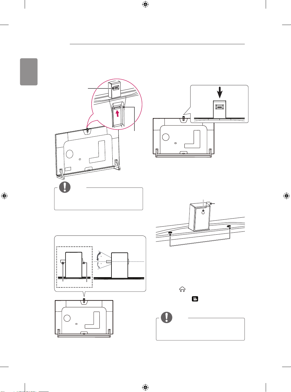
Preparing Built-in Camera
1 Pull up the slide at the back of the TV.
Angle Adjustment
2 You can adjust the angle of the camera with
the angle adjustment lever on the back of the
built-in camera.
Lever
Slide
NOTE
yRemove the protective film before using
the built-in camera.
<Side View>
3 Push down the built-in camera when you are
not using it.
Name of Parts of Built-in Camera
Camera Lens
Protective Film
Microphones
Checking the Camera’s Shooting
Range
Lever
Lens
1 Press the
remote control to display the Launcher menu.
2 Select CAMERA and then press the
Wheel(OK) button.
(Smarthome)
button on the
NOTE
The optimal distance from the camera
y
to use the motion recognition function is
between 1.5 m and 4.5 m.
Page 35
MAKING CONNECTIONS
ANTENNA /
CABLE IN
33
MAKING CONNECTIONS
This section on MAKING CONNECTIONS mainly
uses diagrams for the LB67** models.
Connect various external devices to the TV
and switch input modes to select an external
device. For more information of external device’s
connection, refer to the manual provided with
each device.
Available external devices are: HD receivers,
DVD players, VCRs, audio systems, USB storage
devices, PC, gaming devices, and other external
devices.
NOTE
The external device connection may differ
y
from the model.
(LB86**/LB87** : HDMI/DVI IN 1/2/3/4)
Connect external devices to the TV
y
regardless of the order of the TV port.
If you record a TV program on a DVD
y
recorder or VCR, make sure to connect
the TV signal input cable to the TV
through a DVD recorder or VCR. For
more information of recording, refer to
the manual provided with the connected
device.
yRefer to the external equipment’s manual
for operating instructions.
If you connect a gaming device to the TV,
y
use the cable supplied with the gaming
device.
yIn PC mode, there may be noise
associated with the resolution, vertical
pattern, contrast or brightness. If noise is
present, change the PC output to another
resolution, change the refresh rate to
another rate or adjust the brightness and
contrast on the PICTURE menu until the
picture is clear.
yIn PC mode, some resolution settings
may not work properly depending on the
graphics card.
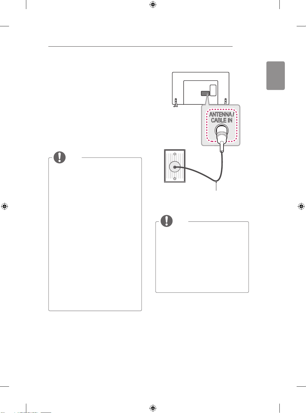
Antenna connection
(*Not Provided)
Connect the TV to a wall antenna socket with an
RF cable (75 Ω).
NOTE
yUse a signal splitter to use more than 2
TVs.
If the image quality is poor, install a signal
y
amplifier properly to improve the image
quality.
yIf the image quality is poor with an
antenna connected, try to realign the
antenna in the correct direction.
An antenna cable and converter are not
y
supplied.
Supported DTV Audio: MPEG, Dolby
y
Digital, Dolby Digital Plus, HE-AAC
ENGLISH
Page 36
34
LNB
Satellite IN
13/18V
700mA Max
MAKING CONNECTIONS
ENGLISH
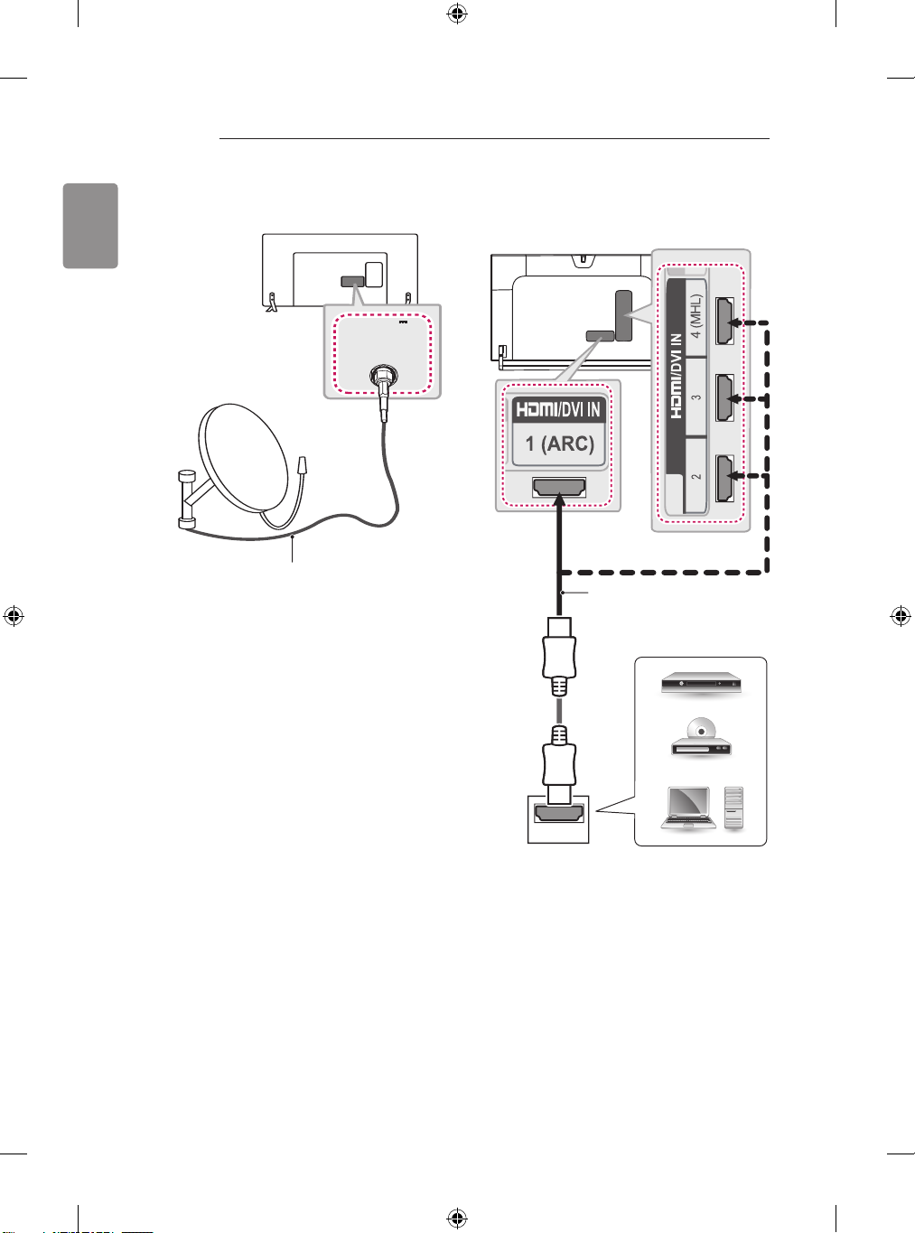
Satellite dish connection
(Only satellite models)
(*Not Provided)
Connect the TV to a satellite dish to a satellite
socket with a satellite RF cable (75 Ω).
HDMI connection
(Only LB86**, LB87**)
(*Not Provided)
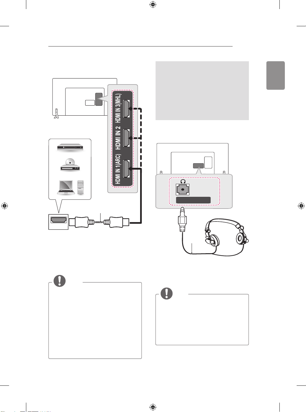
HDMI
DVD/ Blu-Ray / HD Cable
Box / HD STB / PC
Page 37
MAKING CONNECTIONS
Ext.Speaker / H/P OUT
35
(Only LB63**, LB65**, LB67**, LB68**, LB69**,
LB72**, LB73**)
DVD/ Blu-Ray / HD Cable Box
/ HD STB / PC
(*Not Provided)
HDMI
Transmits the digital video and audio signals
from an external device to the TV. Connect the
external device and the TV with the HDMI cable
as shown.
Choose any HDMI input port to connect. It does
not matter which port you use.
NOTE
It is recommended to use the TV with
y
the HDMI connection for the best image
quality.
Use the latest High Speed HDMI™ Cable
y
with CEC (Customer Electronics Control)
function.
High Speed HDMI™ Cables are tested
y
to carry an HD signal up to 1080p and
higher.
Supported HDMI Audio format : Dolby
y
Digital, DTS, PCM (Up to 192 KHz, 32KH
z/44.1KHz/48KHz/88KHz/96KHz/176KHz
/192KHz)
ARC (Audio Return Channel)
An external audio device that supports
y
SIMPLINK and ARC must be connected
using HDMI IN 1 (ARC) or HDMI/DVI IN 1
(ARC) port.
When connected with a high-speed
y
HDMI cable, the external audio device
that supports ARC outputs optical SPDIF
without additional optical audio cable and
supports the SIMPLINK function.
Headphone connection
(*Not
Provided)
Transmits the headphone signal from the TV to
an external device. Connect the external device
and the TV with the headphone as shown.
NOTE
AUDIO menu items are disabled when
y
connecting a headphone.
Optical Digital Audio Out is not available
y
when connecting a headphone.
Headphone impedance: 16 Ω
y
Max audio output of headphone: 0.624
y
mW to 1.04 mW
Headphone jack size: 0.35 cm
y
ENGLISH
Page 38
36
DVI OUT
AUDIO OUT
MAKING CONNECTIONS
ENGLISH
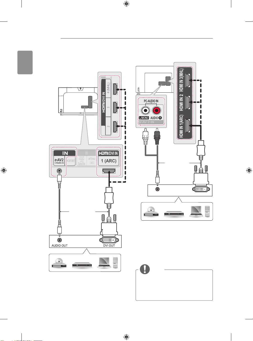
DVI to HDMI connection
(Only LB86**, LB87**)
YELLOW
(Only LB63**, LB65**, LB67**, LB68**, LB69**,
LB72**, LB73**)
WHITE
RED
(*Not Provided)
(*Not Provided)
DVD/ Blu-Ray / HD Cable Box / HD STB / PC
DVD/ Blu-Ray / HD Cable Box / HD STB / PC
Transmits the digital video signal from an external
device to the TV. Connect the external device and
the TV with the DVI-HDMI cable as shown. To
transmit an audio signal, connect an audio cable.
Choose any HDMI input port to connect. It does
not matter which port you use.
NOTE
yDepending on the graphics card, DOS
mode may not work if a HDMI to DVI Cable
is in use.
When using the HDMI/DVI cable, only
y
Single link is supported.
Page 39
MAKING CONNECTIONS
37
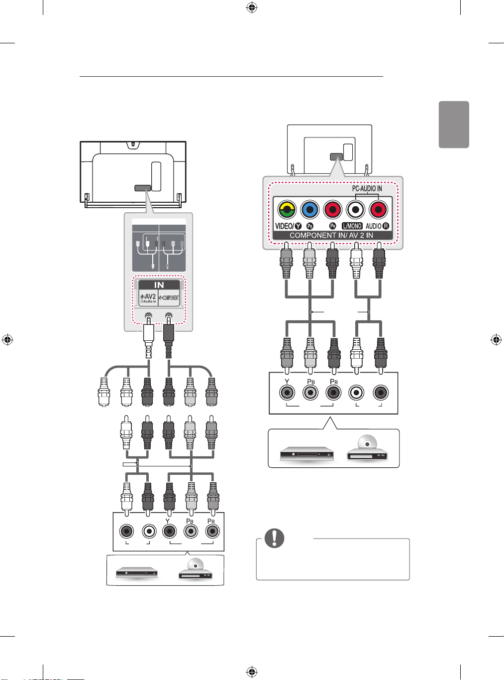
Component connection
(Only LB86**, LB87**)
IN
COMPONENT
VIDEO
(Use the composite
YELLOW
gender cable
provided.)
YELLOW
WHITE
AV2
AUDIO
P
RED
R
P Y
B
GREEN
(Use the
component gender
cable provided.)
RED
BLUE
GREEN
(Only LB63**, LB65**, LB67**, LB68**, LB69**,
LB72**, LB73**)
GREEN
GREEN
BLUE
Provided)
BLUE
RED
(*Not
RED
WHITE
WHITE
L R
RED
RED
ENGLISH
WHITE
RED
(*Not
Provided)
WHITE
RED
L R
AUDIO
DVD / Blu-Ray / HD Cable Box
RED
RED
VIDEO
BLUE
BLUE
GREEN
GREEN
VIDEO
DVD / Blu-Ray / HD Cable Box
Transmits analog video and audio signals from an
external device to the TV. Connect the external
device and the TV with a component cable as
shown.
AUDIO
NOTE
yIf cables are not installed correctly, it
could cause this image to display in black
and white or with distorted colours.
Page 40
38
MAKING CONNECTIONS
ENGLISH
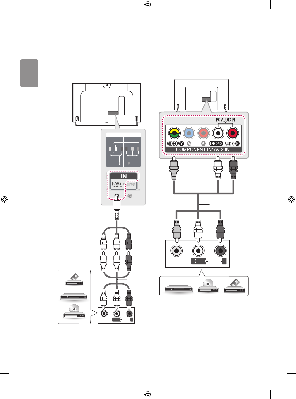
Composite connection
(Only LB86**, LB87**)
AV2
AUDIO
VIDEO
(Use the composite
YELLOW
gender cable
provided.)
YELLOW
IN
COMPONENT
P
R
P Y
WHITE
B
RED
(Only LB63**, LB65**, LB67**, LB68**, LB69**,
LB72**, LB73**)
YELLOW
WHITE
RED
(*Not Provided)
YELLOW
WHITE
RED
DVD / Blu-Ray / HD
Cable Box / VCR
YELLOW
VIDEO
WHITE
YELLOW
WHITE
( )
MONO
AUDIOL R
RED
(*Not
Provided)
RED
VIDEO
( )
MONO
AUDIOL R
DVD/ Blu-Ray / HD Cable Box / VCR
Transmits analog video and audio signals from an
external device to the TV. Connect the external
device and the TV with the composite cable as
shown.
Page 41
MAKING CONNECTIONS
39
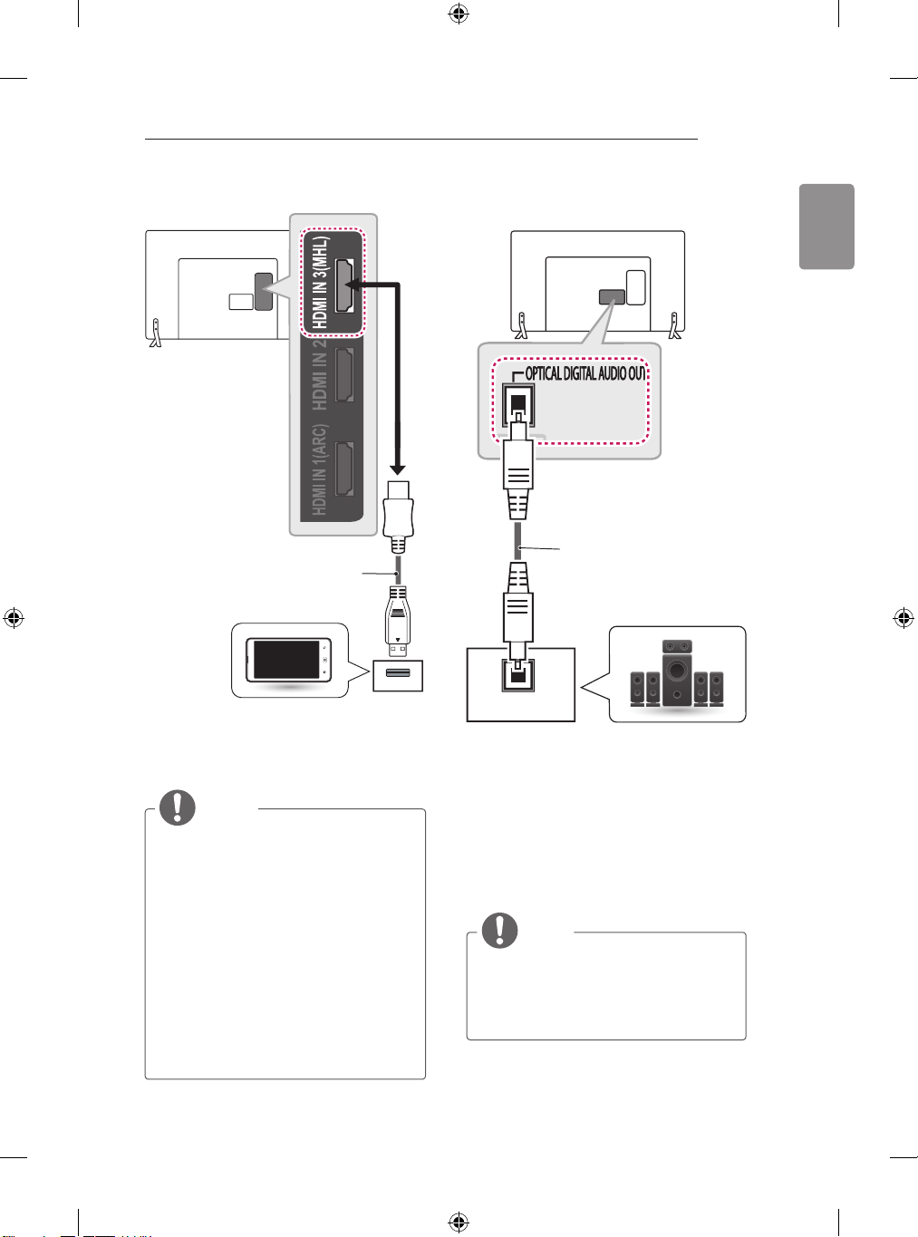
MHL connection
MHL passive cable
(*Not Provided)
Mobile phone
Mobile High-definition Link (MHL) is an interface
for transmitting digital audiovisual signals from
mobile phones to television sets.
NOTE
Connect the mobile phone to the HDMI IN
y
3 (MHL) or HDMI/DVI IN 4 (MHL) port to
view the phone screen on the TV.
The MHL passive cable is needed to
y
connect the TV and a mobile phone.
This only works for the MHL-enabled
y
phone.
Some applications can be operated by the
y
remote control.
For some mobile phones supporting MHL,
y
you can control with the Magic Remote.
Remove the MHL passive cable from the TV
y
when:
- the MHL function is disabled
- your mobile device is fully charged in
standby mode
Audio connection
(*Not Provided)
OPTICAL
AUDIO IN
Digital Audio System
You may use an optional external audio system
instead of the built-in speaker.
Digital optical audio connection
Transmits a digital audio signal from the TV to an
external device. Connect the external device and
the TV with the optical audio cable as shown.
NOTE
Do not look into the optical output port.
y
Looking at the laser beam may damage
your vision.
Audio with ACP (Audio Copy Protection)
y
function may block digital audio output.
ENGLISH
Page 42
40
MAKING CONNECTIONS
ENGLISH
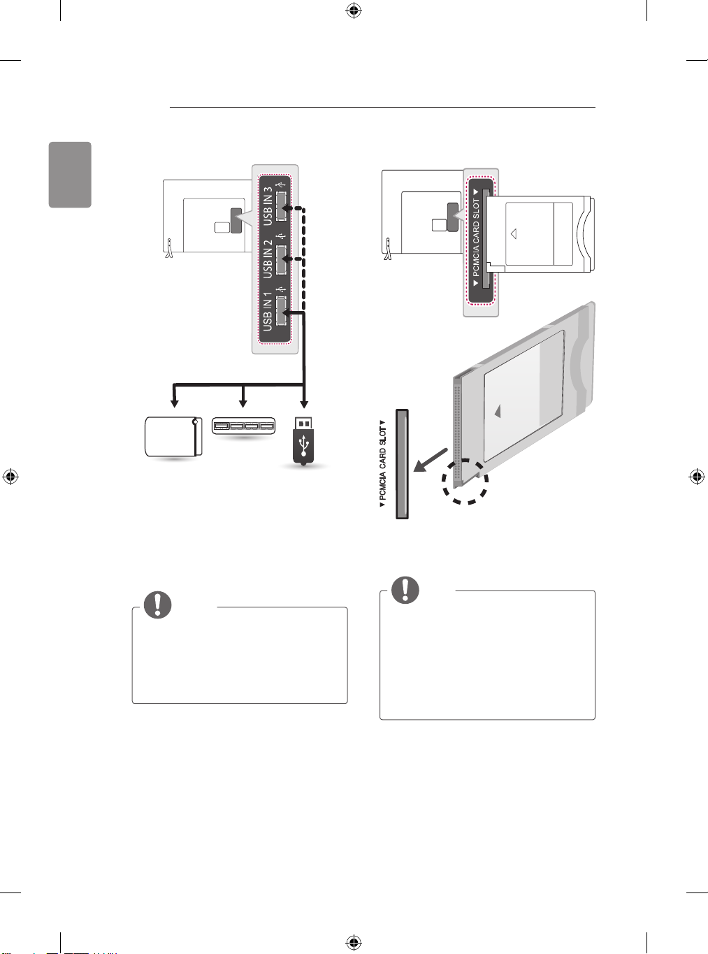
USB connection
HUB
NOTE
(*Not Provided)
USB
(*Not
Provided)
HDD
(*Not
Provided)
Connect a USB storage device such as a USB
flash memory, external hard drive, or a USB
memory card reader to the TV and access the
SmartShare menu to use various multimedia files.
Some USB Hubs may not work. If a USB
y
device connected using a USB Hub is not
detected, connect it to the USB port on
the TV directly.
Connect the external power source if your
y
USB is needed.
CI module connection
(*Not Provided)
View the encrypted (pay) services in digital
TV mode. This feature is not available in all
countries.
NOTE
Check if the CI module is inserted into
y
the PCMCIA CARD SLOT in the right
direction. If the module is not inserted
properly, this can cause damage to the
TV and the PCMCIA card slot.
If the TV does not display any video
y
and audio when CI+ CAM is connected,
please contact to the Terrestrial/Cable/
Satellite Service Operator.
Page 43
MAKING CONNECTIONS
AV1
IN/OUT
41
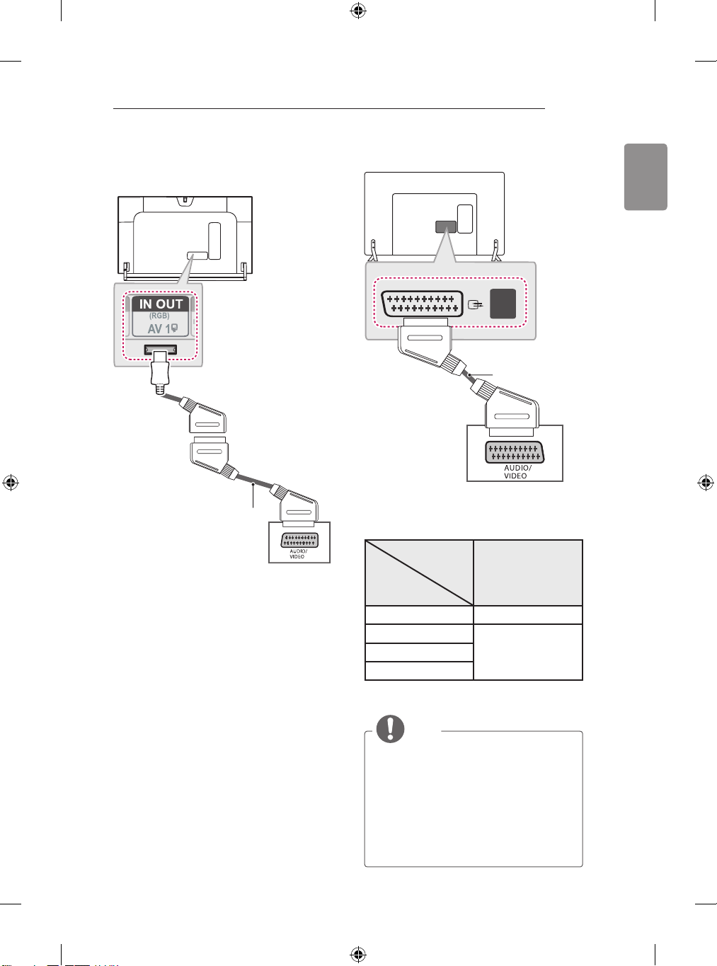
Euro Scart connection
(Only LB86**, LB87**)
(Use the Scart
gender cable
provided.)
(*Not Provided)
(Only LB63**, LB65**, LB67**, LB68**, LB69**,
LB72**, LB73**)
(*Not Provided)
Transmits the video and audio signals from an
external device to the TV set. Connect the
external device and the TV set with the euro scart
cable as shown.
Output
Type
Current
input mode
Digital TV Digital TV
Analogue TV, AV
HDMI
1 TV Out : Outputs Analogue TV or Digital TV
signals.
AV1
(TV Out1)
Analogue TVComponent
ENGLISH
NOTE
Any Euro scart cable used must be signal
y
shielded.
When watching digital TV in 3D imaging mode,
y
only 2D out signals can be output through the
SCART cable. (Only 3D models)
If you set the 3D mode to On while a scheduled
y
recording is performed on digital TV, monitor out
signals cannot be output through the SCART
cable, and the recording cannot be performed.
(Only 3D models)
Page 44
42
REMOTE CONTROL
ENGLISH
REMOTE CONTROL
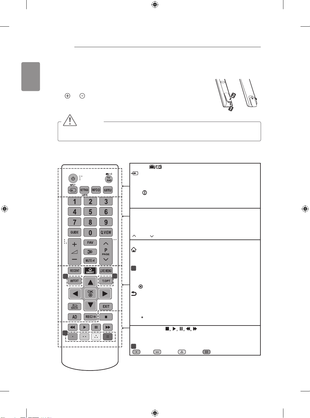
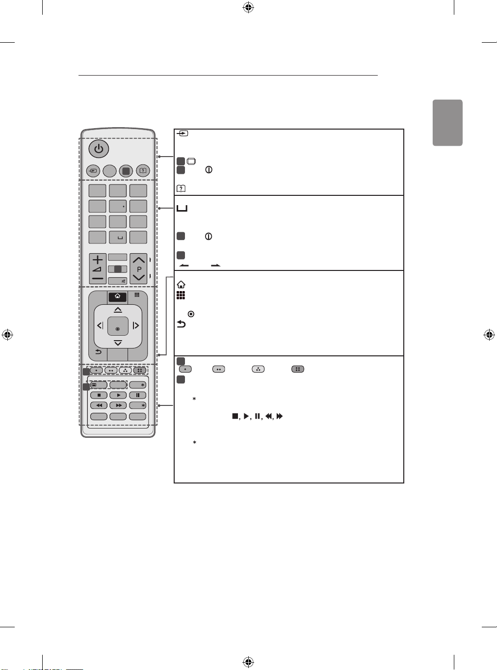
The descriptions in this manual are based on the buttons on the remote control.
Please read this manual carefully and use the TV correctly.
To replace batteries, open the battery cover, replace batteries (1.5 V AAA) matching
the and ends to the label inside the compartment, and close the battery
cover.
To remove the batteries, perform the installation actions in reverse.
CAUTION
Do not mix old and new batteries, as this may damage the remote control.
y
yThe remote control will not be included for all sales market.
Make sure to point the remote control toward the remote control sensor on the TV.
(Depending on model)
TV/RAD Selects Radio, TV and DTV programme.
INPUT Changes the input source.
SETTINGS Accesses the main menus.
Q. MENU Accesses the quick menus.
INFO Views the information of the current programme and
screen.
SUBTITLE Recalls your preferred subtitle in digital mode.
GUIDE Shows programme guide.
Q.VIEW Returns to the previously viewed programme.
FAV Accesses your favourite programme list.
3D Used for viewing 3D video.
PAGE Moves to the previous or next screen.
RECENT Shows the previous history.
SMART Accesses the Smart Home menus.
LIVE MENU Shows the list of Recommended, Programmes, Search
and Recorded.
1
TELETEXT BUTTONS These buttons are used for teletext.
Navigation buttons (up/down/left/right) Scrolls through menus or
1
2
1
options.
OK
Selects menus or options and confirms your input.
BACK Returns to the previous level.
EXIT Clears on-screen displays and returns to TV viewing.
AD By Pressing AD button, audio descriptions function will be
enabled.
REC/
Starts to record and displays record menu. (Only Time
Ready
Machine
Control buttons (
Time Machine
supported model)
Ready
or SmartShare menus or the SIMPLINK
) Controls the Premium contents,
compatible devices (USB or SIMPLINK or Time Machine
2
Colour buttons These access special functions in some menus.
: Red, : Green, : Yellow, : Blue)
(
or
Ready
).
Page 45
REMOTE CONTROL
P
A
G
E
FAV
MUTE
INPUT
EXIT
OK
LIVE MENU
MY APPS
LIVE TV
REC/
TEXT
T.OPT
APP/
AD
BACK
SMART
TV/RAD
SETTINGS
Q.MENU
RECENT
SUBTITLE
1
.,;@
2
abc
3
def
4
ghi
5
jkl
6
mno
7
pqrs
8
tuv
0
9
wxyz
GUIDE
Q.VIEW
43
(Depending on model)
ENGLISH
INPUT Changes the input source.
SETTINGS Accesses the main menus.
Q. MENU Accesses the quick menus.
1
RATIO Resizes an image. (Depending on model)
INFO Views the information of the current programme and screen.
1
1
(Depending on model)
(User Guide) Sees user-guide.
GUIDE Shows programme guide.
(Space) Opens an empty space on the screen keyboard.
Q.VIEW Returns to the previously viewed programme.
FAV Accesses your favourite programme list.
2
INFO Views the information of the current programme and screen.
(Depending on model)
2
3D Used for viewing 3D video. (Depending on model)
PAGE Moves to the previous or next screen.
2
RECENT Shows the previous history.
SMART Accesses the Smart Home menus.
MY APPS Shows the list of Apps.
Navigation buttons (up/down/left/right) Scrolls through menus or options.
OK Selects menus or options and confirms your input.
BACK Returns to the previous level.
LIVE MENU Shows the list of Recommended, Programmes, Search and
Recorded.
EXIT Clears on-screen displays and returns to TV viewing.
3
Colour buttons These access special functions in some menus.
: Red, : Green, : Yellow, : Blue)
3
4
(
4
TELETEXT BUTTONS These buttons are used for teletext.
LIVE TV Returns to LIVE TV.
APP/
Selects the MHP TV menu source. (Only Italy.) (Depending on
model)
Control buttons (
Ready
Machine
or SmartShare menus or the SIMPLINK compatible devices
(USB or SIMPLINK or Time Machine
Starts to record and displays record menu. (Only Time Machine
REC/
Ready
supported model)
) Controls the Premium contents, Time
Ready
).
SUBTITLE Recalls your preferred subtitle in digital mode.
AD By Pressing AD button, audio descriptions function will be enabled.
TV/RAD Selects Radio, TV and DTV programme.
Page 46
44
MAGIC REMOTE FUNCTIONS
ENGLISH
MAGIC REMOTE FUNCTIONS
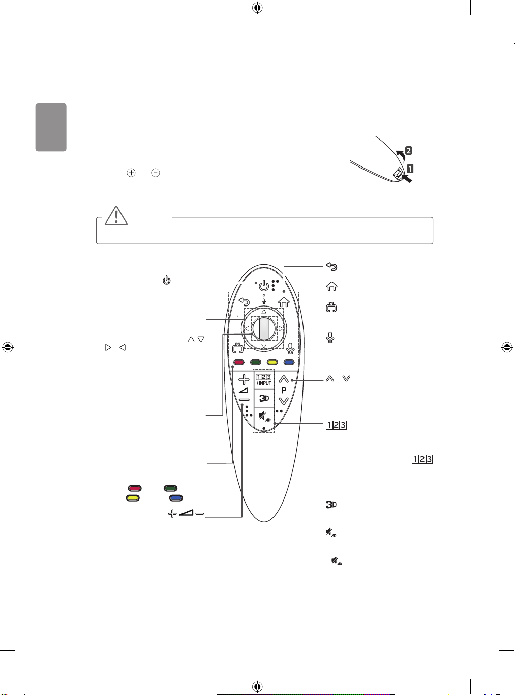
This item is not included for all models.
When the message “Magic Remote battery is low. Change the battery.” is
displayed, replace the battery.
To replace batteries, open the battery cover, replace batteries (1.5 V AA)
matching and ends to the label inside the compartment, and close the
battery cover. Be sure to point the remote control toward the remote control
sensor on the TV.
To remove the batteries, perform the installation actions in reverse.
CAUTION
Do not mix old and new batteries, as this may damage the remote control.
y
(Only LB67**, LB68**, LB69**, LB72**, LB73**, LB86**, LB87**)
Turns the TV on or off.
Navigation buttons
Press the up, down, left or right button
to scroll the menu.If you press
, or buttons while the pointer is in
use, the pointer will disappear from the
screen and Magic Remote will operate
like a general remote control. To display
the pointer on the screen again, shake
Magic Remote to the left and right.
Press the center of the Wheel button
to select a menu. You can change
programmes and scroll the menu by
These access special functions in
(
Adjusts the volume level.
(POWER)
(up/down/left/right)
,
Wheel(OK)
using the Wheel button.
Coloured buttons
some menus.
: Red, : Green,
: Yellow, : Blue)
Returns to the previous level.
Accesses the Smarthome menu.
Swiches among broadcast
(antenna) and various inputs.
(Depending on model)
Scrolls through the saved
programmes.
Displays the Screen Remote.
* Accesses the Universal Control
* Pressing and holding the
Used for viewing 3D video.
(Only 3D models)
Mutes all sounds.
* By Pressing and holding the
(BACK)
(Smarthome)
(EXIT to LIVE)
(Voice recognition)
P
/ INPUT
Menu. (Depending on model)
/ INPUT button will display a
menu to select an external
device that is connected to the
TV.
(MUTE)
button, audio descriptions
function will be enabled.
(Depending on model)
Page 47
MAGIC REMOTE FUNCTIONS
HOME
45
Voice recognition(Depending on model)
Network connection is required to use the
voice recognition function.
1. Press the Voice recognition button.
2. Speak when the voice display window
appears on the left of the TV screen.
• The voice recognition may fail when
you speak too fast or too slow.
• Use the Magic Remote no further than
10 cm from your face.
• The recognition rate may
vary depending on the user’s
characteristics (voice, pronunciation,
intonation and speed) and the
environment (noise and TV volume).
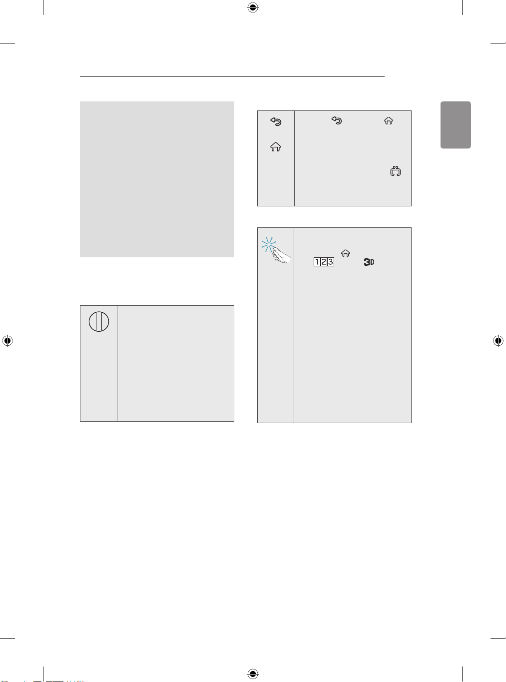
Registering Magic Remote
How to register the Magic Remote
To use the Magic Remote, first
pair it with your TV.
1 Put batteries into the Magic
Remote and turn the TV on.
2 Point the Magic Remote at your
TV and press the Wheel (OK)
on the remote control.
»
If the TV fails to register the
Magic Remote, try again
after turning the TV off and
back on.
How to deregister the Magic Remote
Press the (BACK) and
(BACK)
(S
home)
(Smarthome) buttons at the
same time, for five seconds, to
unpair the Magic Remote with
mart
your TV.
»
Pressing and holding the
(EXIT to LIVE)
let you cancel and re-register
Magic Remote at once.
button will
How to use Magic Remote
Shake the Magic Remote
y
slightly to the right and left
or press (Smarthome),
/ INPUT, buttons
to make the pointer appear
on the screen.
»
The pointer will appear when
you turn the Wheel button.
(Depending on model)
If the pointer has not been
y
used for a certain period
of time or Magic Remote is
placed on a at surface, then
the pointer will disappear.
If the pointer is not
y
responding smoothly, you can
reset the pointer by moving it
to the edge of the screen.
The Magic Remote depletes
y
batteries faster than a normal
remote due to the additional
features.
ENGLISH
Page 48
46
MAGIC REMOTE FUNCTIONS / USING THE USER GUIDE
ENGLISH
Precautions to Take when
Using the Magic Remote
Use the remote control within the specified
y
range (within 10 m).
You may experience communication
failures when using the device outside the
coverage area or if there are obstacles
within the coverage area.
You may experience communication
y
failures depending on the accessories.
Devices such as a microwave oven
and wireless LAN operate in the same
frequency band (2.4 GHz) as the Magic
Remote. This may cause communication
failures.
The Magic Remote may not work properly
y
if a wireless router (AP) is within 1 meter
of the TV. Your wireless router should be
more than 1 m away from the TV.
Do not disassemble or heat the battery.
y
Do not drop the battery. Avoid avoid
y
extreme shocks to the battery.
Inserting the battery the wrong way may
y
result in explosion.
USING THE USER
GUIDE
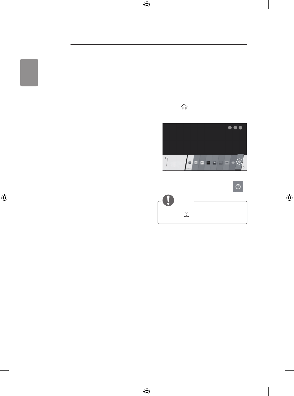
User Guide allows you to more easily access the
detailed TV information.
1 Press the (Smarthome) button on the
remote control to display the Launcher menu.
2 Select User Guide and press Wheel(OK).
NOTE
You can also access the User Guide by
y
pressing
control. (Depending on model)
(User Guide) in the remote
Page 49
MAINTENANCE / TROUBLESHOOTING
47
MAINTENANCE
Cleaning your TV
Clean your TV regularly to keep the best performance and to extend the product lifespan.
CAUTION
Make sure to turn the power off and disconnect the power cord and all other cables first.
y
When the TV is left unattended and unused for a long time, disconnect the power cord from the
y
wall outlet to prevent possible damage from lightning or power surges.
Screen, frame, cabinet and stand
To remove dust or light dirt, wipe the surface with a dry, clean, and soft cloth.
y
To remove major dirt, wipe the surface with a soft cloth dampened in clean water or a diluted mild
y
detergent. Then wipe immediately with a dry cloth.
CAUTION
Avoid touching the screen at all times, as this may result in damage to the screen.
y
yDo not push, rub, or hit the screen surface with your fingernail or a sharp object, as this may result
in scratches and image distortions.
Do not use any chemicals as this may damage the product.
y
Do not spray liquid onto the surface. If water enters the TV, it may result in fire, electric shock, or
y
malfunction.
Power cord
Remove the accumulated dust or dirt on the power cord regularly.
ENGLISH
TROUBLESHOOTING
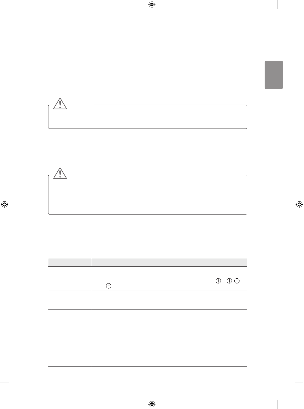
Problem Solution
Cannot control
the TV with the
remote control.
No image display
and no sound is
produced.
The TV turns off
suddenly.
When connecting
to the PC (HDMI/
DVI), ‘No signal’
or ‘Invalid Format’
is displayed.
Check the remote control sensor on the product and try again.
y
Check if there is any obstacle between the product and the remote control.
y
Check if the batteries are still working and properly installed (
y
to ).
Check if the product is turned on.
y
Check if the power cord is connected to a wall outlet.
y
Check if there is a problem in the wall outlet by connecting other products.
y
Check the power control settings. The power supply may be interrupted.
y
Check if the Automatic Standby(Depending on model) / Sleep Timer /
y
Timer Power Off is activated in the Timers settings.
If there is no signal while the TV is on, the TV will turn off automatically after
y
15 minutes of inactivity.
Turn the TV off/on using the remote control.
y
Reconnect the HDMI cable.
y
Restart the PC with the TV on.
y
to ,
Page 50
48
0197
SPECIFICATIONS
ENGLISH
SPECIFICATIONS
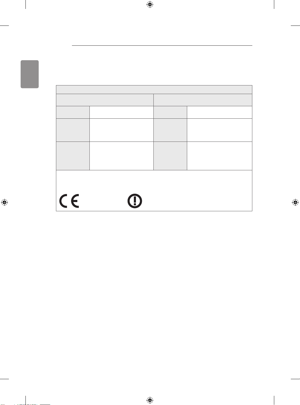
Wireless module(LGSBW41) Specifications
Wireless LAN Bluetooth
Standard IEEE 802.11a/b/g/n Standard Bluetooth Version 3.0
Frequency
Range
Output
Power
(Max.)
Because band channel used by the country could be different, the user can not change or adjust the
y
operating frequency and this product is set for the regional frequency table.
This device should be installed and operated with minimum distance 20 cm between the device and
y
your body. And this phrase is for the general statement for consideration of user environment.
2400 to 2483.5MHz
5150 to 5250 MHz
5725 to 5850 MHz(for Non
EU)
802.11a: 13 dBm
802.11b: 15 dBm
802.11g: 14 dBm
802.11n - 2.4GHz: 16 dBm
802.11n - 5GHz: 16 dBm
Frequency
Range
Output
Power
(Max.)
2400 to 2483.5MHz
10dBm or Lower
Page 51
SPECIFICATIONS
49
Product specifications may be changed without prior notice due to upgrade of product functions.
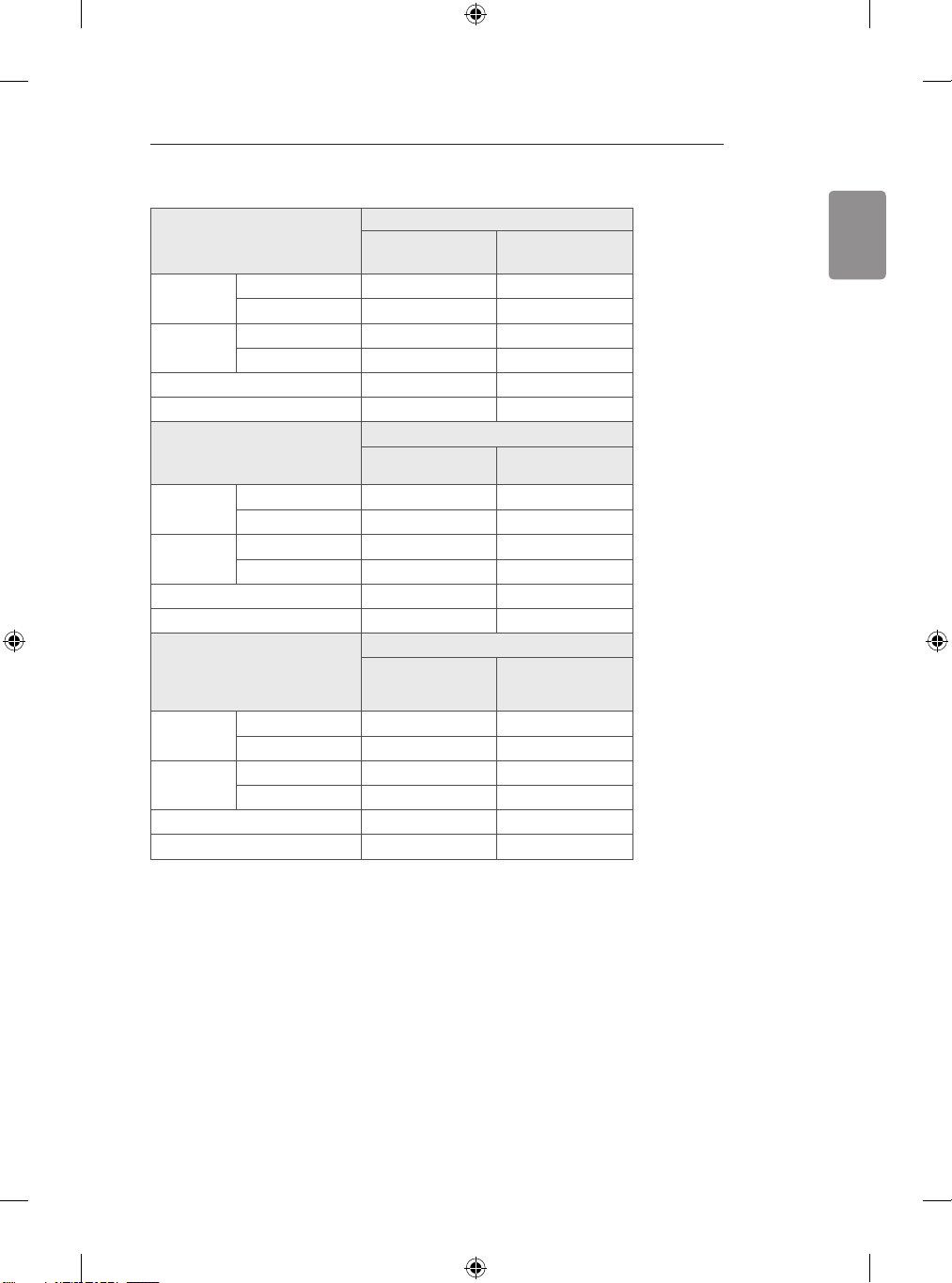
42LB63**
MODELS
Dimensions
(W x H x D)
Weight With stand (kg)
Power requirement
Power consumption
MODELS
Dimensions
(W x H x D)
Weight With stand (kg)
Power requirement
Power consumption
MODELS
Dimensions
(W x H x D)
Weight With stand (kg)
Power requirement
Power consumption
With stand (
Without stand(
Without stand (kg)
With stand (
Without stand(
Without stand (kg)
With stand (
Without stand(
Without stand (kg)
42LB630V-ZA 42LB631V-ZL
960 x 610 x 218 960 x 612 x 193
mm
)
960 x 567 x 54.5 960 x 567 x 54.5
mm)
9.9 9.9
9.6 9.6
AC 100-240 V~ 50 / 60 Hz AC 100-240 V~ 50 / 60 Hz
100 W 100 W
47LB63**
47LB630V-ZA 47LB631V-ZL
1072 x 677 x 247 1072 x 675 x 230
mm
)
1072 x 629 x 54.5 1072 x 629 x 54.5
mm)
13.4 13.3
13.0 13.0
AC 100-240 V~ 50 / 60 Hz AC 100-240 V~ 50 / 60 Hz
110 W 110 W
55LB63**
55LB630V-ZA 55LB631V-ZL
1241 x 772 x 247 1241 x 769 x 224
mm
)
1241 x 725 x 55.5 1241 x 725 x 55.5
mm)
18.7 18.6
18.3 18.3
AC 100-240 V~ 50 / 60 Hz AC 100-240 V~ 50 / 60 Hz
130 W 130 W
ENGLISH
Page 52
50
SPECIFICATIONS
ENGLISH
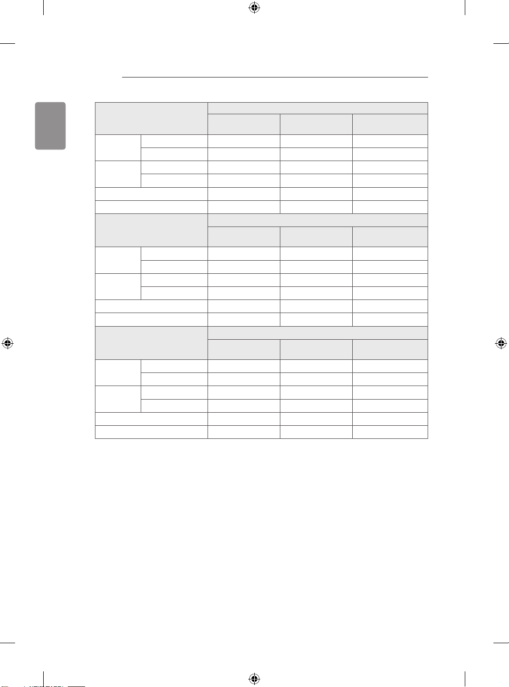
MODELS
Dimensions
(W x H x D)
Weight With stand (kg)
Power requirement
Power consumption
MODELS
Dimensions
(W x H x D)
Weight With stand (kg)
Power requirement
Power consumption
MODELS
Dimensions
(W x H x D)
Weight With stand (kg)
Power requirement
Power consumption
With stand (
Without stand(
Without stand (kg)
With stand (
Without stand(
Without stand (kg)
With stand (
Without stand(
Without stand (kg)
mm
mm
mm
32LB65**
32LB650V-ZA
32LB652V-ZA
731 x 484 x 207 731 x 475 x 207 731 x 474 x 239
)
731 x 437 x 54.5 731 x 437 x 54.5 731 x 437 x 54.5
mm)
6.5 6.5 8.4
6.3 6.3 6.3
AC 100-240 V~ 50 / 60 Hz AC 100-240 V~ 50 / 60 Hz AC 100-240 V~ 50 / 60 Hz
65 W 65 W 65 W
39LB650V-ZA
39LB652V-ZA
884 x 569 x 218 884 x 570 x 193 884 x 564 x 240
)
x
521
x
884
mm)
8.6 8.6 10.7
8.3 8.3 8.3
AC 100-240 V~ 50 / 60 Hz AC 100-240 V~ 50 / 60 Hz AC 100-240 V~ 50 / 60 Hz
90 W 90 W 90 W
42LB650V-ZA
42LB652V-ZA
960 x 610 x 218 960 x 612 x 193 960 x 606 x 238
)
960 x 567 x 54.5 960 x 567 x 54.5 960 x 567 x 54.5
mm)
9.9 9.9 12.1
9.6 9.6 9.6
AC 100-240 V~ 50 / 60 Hz AC 100-240 V~ 50 / 60 Hz AC 100-240 V~ 50 / 60 Hz
100 W 100 W
54.5 884
32LB653V-ZK
39LB65**
39LB653V-ZK
x
521
x
42LB65**
42LB653V-ZK
54.5 884
32LB650V-ZE
32LB650V-ZN
39LB650V-ZE
39LB650V-ZN
x
521
x
42LB650V-ZE
42LB650V-ZN
100 W
54.5
Page 53
SPECIFICATIONS
51
MODELS
Dimensions
(W x H x D)
Weight With stand (kg)
Power requirement
Power consumption
MODELS
Dimensions
(W x H x D)
Weight With stand (kg)
Power requirement
Power consumption
MODELS
Dimensions
(W x H x D)
Weight With stand (kg)
Power requirement
Power consumption
With stand (
Without stand(
Without stand (kg)
With stand (
Without stand(
Without stand (kg)
With stand (
Without stand(
Without stand (kg)
mm
mm
mm
47LB65**
47LB650V-ZA
47LB652V-ZA
1072 x 677 x 247 1072 x 675 x 230 1072 x 669 x 267
)
1072 x 629 x 54.5 1072 x 629 x 54.5 1072 x 629 x 54.5
mm)
13.4 13.3 16.2
13.0 13.0 13.0
AC 100-240 V~ 50 / 60 Hz AC 100-240 V~ 50 / 60 Hz AC 100-240 V~ 50 / 60 Hz
110 W 110 W 110 W
50LB650V-ZA
50LB652V-ZA
1127 x 710 x 247 1127 x 710 x 230 1127 x 710 x 247
)
1127 x 660 x 54.5 1127 x 660 x 54.5 1127 x 660 x 54.5
mm)
14.7 14.6 17.5
14.3 14.3 14.3
AC 100-240 V~ 50 / 60 Hz AC 100-240 V~ 50 / 60 Hz AC 100-240 V~ 50 / 60 Hz
120 W 120 W 120 W
55LB650V-ZA
55LB652V-ZA
1241 x 772 x 247 1241 x 769 x 224 1241 x 765 x 293
)
1241 x 725 x 55.5 1241 x 725 x 55.5 1241 x 725 x 55.5
mm)
18.7 18.6 22.8
18.3 18.3 18.3
AC 100-240 V~ 50 / 60 Hz AC 100-240 V~ 50 / 60 Hz AC 100-240 V~ 50 / 60 Hz
130 W 130 W 130 W
47LB653V-ZK
50LB65**
50LB653V-ZK
55LB65**
55LB653V-ZK
47LB650V-ZE
47LB650V-ZN
50LB650V-ZE
50LB650V-ZN
55LB650V-ZE
55LB650V-ZN
ENGLISH
Page 54
52
SPECIFICATIONS
ENGLISH
MODELS
Dimensions
(W x H x D)
Weight With stand (kg)
Power requirement
Power consumption
MODELS
Dimensions
(W x H x D)
Weight With stand (kg)
Power requirement
Power consumption
MODELS
Dimensions
(W x H x D)
Weight With stand (kg)
Power requirement
Power consumption
With stand (
Without stand(
Without stand (kg)
With stand (
Without stand(
Without stand (kg)
With stand (
Without stand(
Without stand (kg)
mm
mm
mm
60LB65** 70LB65**
60LB650V-ZN
1351 x 828 x 293 1574 x 964 x 344
)
1351 x 785 x 57.5 1574 x 916 x 60.2
mm)
26.0
21.8
AC 100-240 V~ 50 / 60 Hz AC 100-240 V~ 50 / 60 Hz
130 W 260 W
42LB67** 47LB67** 50LB67**
42LB670V-ZA
42LB671V-ZB
42LB671V-ZF
42LB673V-ZB
42LB675V-ZA
42LB677V-ZC
42LB679V-ZF
948.2 x 606.9 x 210.9
)
948.2 x 558.2 x 55.1 1059.9
mm)
10.1 13.2 14.6
9.7 12.7 14.1
AC 100-240 V~ 50 / 60 Hz AC 100-240 V~ 50 / 60 Hz AC 100-240 V~ 50 / 60 Hz
95 W 100 W 110 W
55LB67** 42LB68** 47LB68**
55LB670V-ZA
55LB671V-ZB
55LB671V-ZF
55LB673V-ZB
55LB675V-ZA
55LB677V-ZC
55LB679V-ZF
1229.8 x 767.5 x 247.5
)
1229.8 x 708.6 x 55.1
mm)
18.5 10.3 13.3
18 10 12.8
AC 100-240 V~ 50 / 60 Hz AC 100-240 V~ 50 / 60 Hz AC 100-240 V~ 50 / 60 Hz
130 W 95 W 100 W
70LB650V-ZA
70LB650V-ZB
31.6
30.1
47LB670V-ZA
47LB671V-ZB
47LB671V-ZF
47LB673V-ZB
47LB675V-ZA
47LB677V-ZC
47LB679V-ZF
1059.9 x 671.9 x 247.5
x
621
x
42LB680V-ZA
42LB680V-ZD
949 x 608 x 211 1061 x 670 x 247
949 x 560 x 55.1 1061 x 623 x 55.1
50LB670V-ZA
50LB671V-ZB
50LB671V-ZF
50LB673V-ZB
50LB675V-ZA
50LB677V-ZC
50LB679V-ZF
1116.1 x 704.9 x 247.5
55.1 1116.1 x 652.9 x 55.1
47LB680V-ZA
47LB680V-ZD
Page 55
SPECIFICATIONS
53
MODELS
Dimensions
(W x H x D)
Weight With stand (kg)
Power requirement
Power consumption
MODELS
Dimensions
(W x H x D)
Weight With stand (kg)
Power requirement
Power consumption
MODELS
Dimensions
(W x H x D)
Weight With stand (kg)
Power requirement
Power consumption
With stand (
Without stand(
Without stand (kg)
With stand (
Without stand(
Without stand (kg)
With stand (
Without stand(
Without stand (kg)
55LB68** 60LB68** 65LB68**
55LB680V-ZA
55LB680V-ZD
1231 x 769 x 247
mm
)
1231 x 718 x 55.1 1338.4 x 778.8 x 58.1
mm)
19 22.2 27.9
18.5 21.3 26.5
AC 100-240 V~ 50 / 60 Hz AC 100-240 V~ 50 / 60 Hz AC 100-240 V~ 50 / 60 Hz
130 W 140 W
42LB69** 47LB69** 55LB69**
42LB690V-ZA
42LB690V-ZC
949 x 608 x 211 1061 x 670 x 247 1231 x 769 x 247
mm
)
949 x 560 x 55.1 1061 x 623 x 55.1 1231 x 718 x 55.1
mm)
10.3 13.3 19
10 12.8 18.5
AC 100-240 V~ 50 / 60 Hz AC 100-240 V~ 50 / 60 Hz AC 100-240 V~ 50 / 60 Hz
95 W 100 W 130 W
42LB72** 47LB72** 55LB72**
42LB720V-ZA
42LB720V-ZB
42LB720V-ZG
949 x 608 x 211 1061 x 670 x 247 1231 x 769 x 247
mm
)
949 x 560 x 55.1 1061 x 623 x 55.1 1231 x 718 x 55.1
mm)
10.3 13.3 19
10 12.8 18.5
AC 100-240 V~ 50 / 60 Hz AC 100-240 V~ 50 / 60 Hz AC 100-240 V~ 50 / 60 Hz
95 W 100 W 130 W
60LB680V-ZA
60LB680V-ZD
1338.4 x 834.7 x 288.9 1449.5 x 883.7 x 313.9
47LB690V-ZA
47LB690V-ZC
47LB720V-ZA
47LB720V-ZB
47LB720V-ZG
65LB680V-ZA
65LB680V-ZD
1449.5 x 840.8 x 58.1
160 W
55LB690V-ZA
55LB690V-ZC
55LB720V-ZA
55LB720V-ZB
55LB720V-ZG
ENGLISH
Page 56
54
SPECIFICATIONS
ENGLISH
MODELS
Dimensions
(W x H x D)
Weight With stand (kg)
Power requirement
Power consumption
MODELS
Dimensions
(W x H x D)
Weight With stand (kg)
Power requirement
Power consumption
MODELS
Dimensions
(W x H x D)
Weight With stand (kg)
Power requirement
Power consumption
With stand (
Without stand(
Without stand (kg)
With stand (
Without stand(
Without stand (kg)
With stand (
Without stand(
Without stand (kg)
mm
mm
mm
60LB72** 65LB72**
60LB720V-ZA
60LB720V-ZB
60LB720V-ZG
1338.4 x 834.7 x 288.9 1449.5 x 883.7 x 313.9
)
1338.4 x 778.8 x 58.1
mm)
22.2 27.9
21.3 26.5
AC 100-240 V~ 50 / 60 Hz AC 100-240 V~ 50 / 60 Hz
140 W
42LB730V-ZA
949 x 608 x 211 949 x 607.7 x 213.4
)
949 x 560 x 55.1 949 x 560 x 55.1
mm)
10.3 10.7
10 10
AC 100-240 V~ 50 / 60 Hz AC 100-240 V~ 50 / 60 Hz
95 W 95 W
47LB730V-ZA
1061 x 670 x 247 1061 x 666 x 227
)
1061 x 623 x 55.1 1061 x 623 x 55.1
mm)
13.3 13.7
12.8 12.8
AC 100-240 V~ 50 / 60 Hz AC 100-240 V~ 50 / 60 Hz
100 W 100 W
65LB720V-ZA
65LB720V-ZB
65LB720V-ZG
1449.5 x 840.8 x 58.1
160 W
42LB73**
42LB730V-ZD
42LB731V-ZE
47LB73**
47LB730V-ZD
47LB731V-ZE
Page 57
SPECIFICATIONS
55
MODELS
Dimensions
(W x H x D)
Weight With stand (kg)
Power requirement
Power consumption
MODELS
Dimensions
(W x H x D)
Weight With stand (kg)
Power requirement
Power consumption
MODELS
Dimensions
(W x H x D)
Weight With stand (kg)
Power requirement
Power consumption
With stand (
Without stand(
Without stand (kg)
With stand (
Without stand(
Without stand (kg)
With stand (
Without stand(
Without stand (kg)
55LB73**
55LB730V-ZA
1231 x 769 x 247 1231 x 766 x 237
mm
)
1231 x 718 x 55.1 1231 x 718 x 55.1
mm)
19 19.6
18.5 18.5
AC 100-240 V~ 50 / 60 Hz AC 100-240 V~ 50 / 60 Hz
130 W 130 W
60LB730V-ZA
1338.4 x 834.7 x 288.9 1338.4 x 826.6 x 268.4
mm
)
1338.4 x 778.8 x 58.1 1338.4 x 778.8 x 58.1
mm)
22.2 22.6
21.3 21.3
AC 100-240 V~ 50 / 60 Hz AC 100-240 V~ 50 / 60 Hz
140 W 140 W
65LB730V-ZA
1449.5 x 883.7 x 313.9 1449.5 x 894.4 x 293.1
mm
)
1449.5 x 840.8 x 58.1 1449.5 x 840.8 x 58.1
mm)
27.9 27.9
26.5 26.5
AC 100-240 V~ 50 / 60 Hz AC 100-240 V~ 50 / 60 Hz
160 W 160 W
55LB730V-ZD
55LB731V-ZE
60LB73**
60LB730V-ZD
60LB731V-ZE
65LB73**
65LB730V-ZD
65LB731V-ZE
ENGLISH
Page 58
56
SPECIFICATIONS
ENGLISH
49LB86** 55LB86** 60LB86**
MODELS
Dimensions
(W x H x D)
Weight With stand (kg)
Power requirement
Power consumption
MODELS
Dimensions
(W x H x D)
Weight With stand (kg)
Power requirement
Power consumption
CI Module Size (W x H x D) 100.0 mm x 55.0 mm x 5.0 mm
With stand (
Without stand(
With Sound Bar
Supporter(mm)
Without stand (kg)
With stand (
Without stand(
With Sound Bar
Supporter(mm)
Without stand (kg)
Operating Temperature
49LB860V-ZA
49LB860V-ZB
1091 x 690 x 229 1227 x 769 x 229 1335 x 830 x 261
mm
)
x
632
x
1091
mm)
1091
17.4 22.6 27.1
16.7 21.9 26.2
AC 100-240 V~ 50 / 60 Hz AC 100-240 V~ 50 / 60 Hz AC 100-240 V~ 50 / 60 Hz
120 W 130 W 140 W
49LB87** 55LB87** 60LB87**
49LB870V-ZA 55LB870V-ZA 60LB870V-ZA
1091 x 690 x 229 1227 x 769 x 229 1335 x 830 x 261
mm
)
1091
mm)
1091
17.4 22.6 27.1
16.7 21.9 26.2
AC 100-240 V~ 50 / 60 Hz AC 100-240 V~ 50 / 60 Hz AC 100-240 V~ 50 / 60 Hz
120 W 130 W 140 W
34.7 1227 x 709 x 34.7 1335 x 770 x 35.7
x
688
x
34.7 1227 x 765 x 34.7 1335 x 826 x 35.7
x
632
x
34.7 1227 x 709 x 34.7 1335 x 770 x 35.7
x
688
x
34.7 1227 x 765 x 34.7 1335 x 826 x 35.7
55LB860V-ZA
55LB860V-ZB
0 °C to 40 °C
60LB860V-ZA
60LB860V-ZB
Environment
condition
Television system
Programme coverage
Maximum number of
storable programmes
External antenna impedance 75 Ω
Operating Humidity
Storage Temperature
Storage Humidity
DVB-T/T2
DVB-C
DVB-S/S2
VHF, UHF
C-Band, Ku-Band
DVB-S/S2 : 6,000
DVB-T/T2/C & Analogue TV : 1,500
Less than 80 %
-20 °C to 60 °C
Less than 85 %
Digital TV Analogue TV
PAL/SECAM B/G/I/D/K
SECAM L/L’
VHF: E2 to E12, UHF : E21 to E69,
CATV: S1 to S20, HYPER: S21 to
S47
Page 59
Page 60
Page 61
Page 62
Record the model number and serial number of
the TV.
Refer to the label on the back cover and quote
this information to your dealer when requiring
any service.
MODEL
SERIAL
Please contact LG First.
If you have any inquiries or comments,
please contact LG customer information centre.
LG Customer Information Centre
Country
Latvija
Service
0 810 144 131 0900 543 5454
015 200 255 800 187 40
0032 15 200255 801 54 54 54
07001 54 54 808 78 54 54
810 555 810 031 228 3542
8088 5758 0850 111 154
0800 0 54 54 902 500 234
3220 54
01806-11-54-11
(0,20€ pro Anruf
aus dem Festnetz der
DTAG; Mobilfunk: max.
0,60€ pro Anruf.)
801 11 200 900,
210 4800 564
06 40 54 54 54 800 9990
0818 27 6955 0 800 303 000
199600099
8 820 0071 1111
80200201
880008081 8 0000 710 005
Country
Service
0770 54 54 54
0848 543 543
0844 847 5454
8 800 200 7676
8 8000 805 805,
2255(GSM)
8 800 120 2222
 Loading...