

Page 1
Internal Use Only
North/Latin America http://aic.lgservice.com
Europe/Africa http://eic.lgservice.com
Asia/Oceania http://biz.lgservice.com
OLED TV
SERVICE MANUAL
CHASSIS : ED42D
MODEL : 55EC900V 55EC900V-ZB
CAUTION
BEFORE SERVICING THE CHASSIS,
READ THE SAFETY PRECAUTIONS IN THIS MANUAL.
Printed in KoreaP/NO : MFL68522305 (1508-REV00)
Page 2

CONTENTS
CONTENTS .............................................................................................. 2
SAFETY PRECAUTIONS ........................................................................ 3
SERVICING PRECAUTIONS .................................................................... 4
SPECIFICATION ....................................................................................... 6
ADJUSTMENT INSTRUCTION .............................................................. 13
BLOCK DIAGRAM ................................................................................. 20
EXPLODED VIEW .................................................................................. 30
SCHEMATIC CIRCUIT DIAGRAM ............................................APPENDIX
TROUBLE SHOOTING GUIDE ................................................ APPENDIX
Only for training and service purposes
- 2 -
LGE Internal Use OnlyCopyright © LG Electronics. Inc. All rights reserved.
Page 3
SAFETY PRECAUTIONS
IMPORTANT SAFETY NOTICE
Many electrical and mechanical parts in this chassis have special safety-related characteristics. These parts are identified by in the
Schematic Diagram and Exploded View.
It is essential that these special safety parts should be replaced with the same components as recommended in this manual to prevent
Shock, Fire, or other Hazards.
Do not modify the original design without permission of manufacturer.
General Guidance
An isolation Transformer should always be used during the
servicing of a receiver whose chassis is not isolated from the AC
power line. Use a transformer of adequate power rating as this
protects the technician from accidents resulting in personal injury
from electrical shocks.
It will also protect the receiver and it's components from being
damaged by accidental shorts of the circuitry that may be
inadvertently introduced during the service operation.
If any fuse (or Fusible Resistor) in this TV receiver is blown,
replace it with the specified.
When replacing a high wattage resistor (Oxide Metal Film Resistor,
over 1 W), keep the resistor 10 mm away from PCB.
Keep wires away from high voltage or high temperature parts.
Before returning the receiver to the customer,
always perform an AC leakage current check on the exposed
metallic parts of the cabinet, such as antennas, terminals, etc., to
be sure the set is safe to operate without damage of electrical
shock.
Leakage Current Cold Check(Antenna Cold Check)
With the instrument AC plug removed from AC source, connect an
electrical jumper across the two AC plug prongs. Place the AC
switch in the on position, connect one lead of ohm-meter to the AC
plug prongs tied together and touch other ohm-meter lead in turn to
each exposed metallic parts such as antenna terminals, phone
jacks, etc.
If the exposed metallic part has a return path to the chassis, the
measured resistance should be between 1 MΩ and 5.2 MΩ.
When the exposed metal has no return path to the chassis the
reading must be infinite.
An other abnormality exists that must be corrected before the
receiver is returned to the customer.
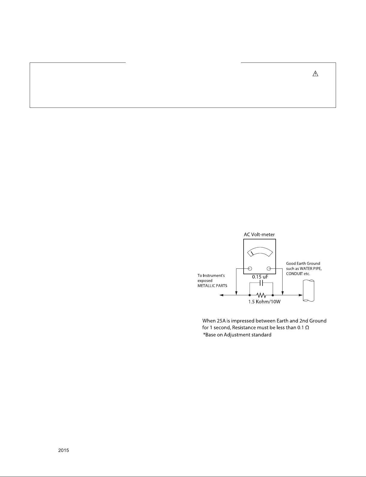
Leakage Current Hot Check (See below Figure)
Plug the AC cord directly into the AC outlet.
Do not use a line Isolation Transformer during this check.
Connect 1.5 K / 10 watt resistor in parallel with a 0.15 uF capacitor
between a known good earth ground (Water Pipe, Conduit, etc.)
and the exposed metallic parts.
Measure the AC voltage across the resistor using AC voltmeter
with 1000 ohms/volt or more sensitivity.
Reverse plug the AC cord into the AC outlet and repeat AC voltage
measurements for each exposed metallic part. Any voltage
measured must not exceed 0.75 volt RMS which is corresponds to
0.5 mA.
In case any measurement is out of the limits specified, there is
possibility of shock hazard and the set must be checked and
repaired before it is returned to the customer.
Leakage Current Hot Check circuit
Only for training and service purposes
- 3 -
LGE Internal Use OnlyCopyright © LG Electronics. Inc. All rights reserved.
Page 4

SERVICING PRECAUTIONS
CAUTION: Before servicing receivers covered by this service
manual and its supplements and addenda, read and follow the
SAFETY PRECAUTIONS on page 3 of this publication.
NOTE: If unforeseen circumstances create conict between the
following servicing precautions and any of the safety precautions
on page 3 of this publication, always follow the safety precautions. Remember: Safety First.
General Servicing Precautions
1. Always unplug the receiver AC power cord from the AC power
source before;
a. Removing or reinstalling any component, circuit board
module or any other receiver assembly.
b. Disconnecting or reconnecting any receiver electrical plug
or other electrical connection.
c. Connecting a test substitute in parallel with an electrolytic
capacitor in the receiver.
CAUTION: A wrong part substitution or incorrect polarity
installation of electrolytic capacitors may result in an explosion hazard.
2. Test high voltage only by measuring it with an appropriate
high voltage meter or other voltage measuring device (DVM,
FETVOM, etc) equipped with a suitable high voltage probe.
Do not test high voltage by "drawing an arc".
3. Do not spray chemicals on or near this receiver or any of its
assemblies.
4. Unless specied otherwise in this service manual, clean
electrical contacts only by applying the following mixture to the
contacts with a pipe cleaner, cotton-tipped stick or comparable
non-abrasive applicator; 10 % (by volume) Acetone and 90 %
(by volume) isopropyl alcohol (90 % - 99 % strength)
CAUTION: This is a ammable mixture.
Unless specied otherwise in this service manual, lubrication
of contacts in not required.
5. Do not defeat any plug/socket B+ voltage interlocks with which
receivers covered by this service manual might be equipped.
6. Do not apply AC power to this instrument and/or any of its
electrical assemblies unless all solid-state device heat sinks
are correctly installed.
7. Always connect the test receiver ground lead to the receiver
chassis ground before connecting the test receiver positive
lead.
Always remove the test receiver ground lead last.
8. Use with this receiver only the test xtures specied in this
service manual.
CAUTION: Do not connect the test xture ground strap to any
heat sink in this receiver.
Electrostatically Sensitive (ES) Devices
Some semiconductor (solid-state) devices can be damaged easily by static electricity. Such components commonly are called
Electrostatically Sensitive (ES) Devices. Examples of typical ES
devices are integrated circuits and some eld-effect transistors
and semiconductor “chip” components. The following techniques
should be used to help reduce the incidence of component damage caused by static by static electricity.
1. Immediately before handling any semiconductor component or
semiconductor-equipped assembly, drain off any electrostatic
charge on your body by touching a known earth ground. Alternatively, obtain and wear a commercially available discharging wrist strap device, which should be removed to prevent
potential shock reasons prior to applying power to the unit
under test.
2. After removing an electrical assembly equipped with ES
devices, place the assembly on a conductive surface such as
aluminum foil, to prevent electrostatic charge buildup or exposure of the assembly.
3. Use only a grounded-tip soldering iron to solder or unsolder
ES devices.
4. Use only an anti-static type solder removal device. Some sol-
der removal devices not classied as “anti-static” can generate
electrical charges sufcient to damage ES devices.
5. Do not use freon-propelled chemicals. These can generate
electrical charges sufcient to damage ES devices.
6. Do not remove a replacement ES device from its protective
package until immediately before you are ready to install it.
(Most replacement ES devices are packaged with leads electrically shorted together by conductive foam, aluminum foil or
comparable conductive material).
7. Immediately before removing the protective material from the
leads of a replacement ES device, touch the protective material to the chassis or circuit assembly into which the device will
be installed.
CAUTION: Be sure no power is applied to the chassis or circuit, and observe all other safety precautions.
8. Minimize bodily motions when handling unpackaged replacement ES devices. (Otherwise harmless motion such as the
brushing together of your clothes fabric or the lifting of your
foot from a carpeted oor can generate static electricity sufcient to damage an ES device.)
General Soldering Guidelines
1. Use a grounded-tip, low-wattage soldering iron and appropriate tip size and shape that will maintain tip temperature within
the range or 500 °F to 600 °F.
2. Use an appropriate gauge of RMA resin-core solder composed
of 60 parts tin/40 parts lead.
3. Keep the soldering iron tip clean and well tinned.
4. Thoroughly clean the surfaces to be soldered. Use a mall wirebristle (0.5 inch, or 1.25 cm) brush with a metal handle.
Do not use freon-propelled spray-on cleaners.
5. Use the following unsoldering technique
a. Allow the soldering iron tip to reach normal temperature.
(500 °F to 600 °F)
b. Heat the component lead until the solder melts.
c. Quickly draw the melted solder with an anti-static, suction-
type solder removal device or with solder braid.
CAUTION: Work quickly to avoid overheating the circuit
board printed foil.
6. Use the following soldering technique.
a. Allow the soldering iron tip to reach a normal temperature
(500 °F to 600 °F)
b. First, hold the soldering iron tip and solder the strand
against the component lead until the solder melts.
c. Quickly move the soldering iron tip to the junction of the
component lead and the printed circuit foil, and hold it there
only until the solder ows onto and around both the component lead and the foil.
CAUTION: Work quickly to avoid overheating the circuit
board printed foil.
d. Closely inspect the solder area and remove any excess or
splashed solder with a small wire-bristle brush.
Only for training and service purposes
- 4 -
LGE Internal Use OnlyCopyright © LG Electronics. Inc. All rights reserved.
Page 5

IC Remove/Replacement
Some chassis circuit boards have slotted holes (oblong) through
which the IC leads are inserted and then bent at against the circuit foil. When holes are the slotted type, the following technique
should be used to remove and replace the IC. When working with
boards using the familiar round hole, use the standard technique
as outlined in paragraphs 5 and 6 above.
Removal
1. Desolder and straighten each IC lead in one operation by
gently prying up on the lead with the soldering iron tip as the
solder melts.
2. Draw away the melted solder with an anti-static suction-type
solder removal device (or with solder braid) before removing
the IC.
Replacement
1. Carefully insert the replacement IC in the circuit board.
2. Carefully bend each IC lead against the circuit foil pad and
solder it.
3. Clean the soldered areas with a small wire-bristle brush.
(It is not necessary to reapply acrylic coating to the areas).
"Small-Signal" Discrete Transistor
Removal/Replacement
1. Remove the defective transistor by clipping its leads as close
as possible to the component body.
2. Bend into a "U" shape the end of each of three leads remaining on the circuit board.
3. Bend into a "U" shape the replacement transistor leads.
4. Connect the replacement transistor leads to the corresponding
leads extending from the circuit board and crimp the "U" with
long nose pliers to insure metal to metal contact then solder
each connection.
Power Output, Transistor Device
Removal/Replacement
1. Heat and remove all solder from around the transistor leads.
2. Remove the heat sink mounting screw (if so equipped).
3. Carefully remove the transistor from the heat sink of the circuit
board.
4. Insert new transistor in the circuit board.
5. Solder each transistor lead, and clip off excess lead.
6. Replace heat sink.
Diode Removal/Replacement
1. Remove defective diode by clipping its leads as close as possible to diode body.
2. Bend the two remaining leads perpendicular y to the circuit
board.
3. Observing diode polarity, wrap each lead of the new diode
around the corresponding lead on the circuit board.
4. Securely crimp each connection and solder it.
5. Inspect (on the circuit board copper side) the solder joints of
the two "original" leads. If they are not shiny, reheat them and
if necessary, apply additional solder.
3. Solder the connections.
CAUTION: Maintain original spacing between the replaced
component and adjacent components and the circuit board to
prevent excessive component temperatures.
Circuit Board Foil Repair
Excessive heat applied to the copper foil of any printed circuit
board will weaken the adhesive that bonds the foil to the circuit
board causing the foil to separate from or "lift-off" the board. The
following guidelines and procedures should be followed whenever this condition is encountered.
At IC Connections
To repair a defective copper pattern at IC connections use the
following procedure to install a jumper wire on the copper pattern
side of the circuit board. (Use this technique only on IC connections).
1. Carefully remove the damaged copper pattern with a sharp
knife. (Remove only as much copper as absolutely necessary).
2. carefully scratch away the solder resist and acrylic coating (if
used) from the end of the remaining copper pattern.
3. Bend a small "U" in one end of a small gauge jumper wire and
carefully crimp it around the IC pin. Solder the IC connection.
4. Route the jumper wire along the path of the out-away copper
pattern and let it overlap the previously scraped end of the
good copper pattern. Solder the overlapped area and clip off
any excess jumper wire.
At Other Connections
Use the following technique to repair the defective copper pattern
at connections other than IC Pins. This technique involves the
installation of a jumper wire on the component side of the circuit
board.
1. Remove the defective copper pattern with a sharp knife.
Remove at least 1/4 inch of copper, to ensure that a hazardous
condition will not exist if the jumper wire opens.
2. Trace along the copper pattern from both sides of the pattern
break and locate the nearest component that is directly connected to the affected copper pattern.
3. Connect insulated 20-gauge jumper wire from the lead of the
nearest component on one side of the pattern break to the
lead of the nearest component on the other side.
Carefully crimp and solder the connections.
CAUTION: Be sure the insulated jumper wire is dressed so the
it does not touch components or sharp edges.
Fuse and Conventional Resistor
Removal/Replacement
1. Clip each fuse or resistor lead at top of the circuit board hollow
stake.
2. Securely crimp the leads of replacement component around
notch at stake top.
Only for training and service purposes
- 5 -
LGE Internal Use OnlyCopyright © LG Electronics. Inc. All rights reserved.
Page 6
SPECIFICATION
NOTE : Specifications and others are subject to change without notice for improvement
.
1. Application range
This specification is applied to the OLED TV used ED42D
chassis.
2. Requirement for Test
Each part is tested as below without special appointment.
(1) Temperature: 25 °C ± 5 °C(77 °F ± 9 °F), CST: 40 °C ± 5 °C
(2) Relative Humidity: 65 % ± 10 %
(3) Power Voltage
: Standard input voltage (AC 100-240 V~, 50/60 Hz)
* Standard Voltage of each products is marked by models.
(4) Specification and performance of each parts are followed
each drawing and specification by part number in
accordance with BOM.
(5) The receiver must be operated for about 5 minutes prior to
the adjustment.
3. Test method
1) Performance: LGE TV test method followed
2) Demanded other specification
- Safety : CE, IEC specification
- EMC : CE, IEC
4. Model General Specification
No. Item Specication Remarks
1 Market EU(PAL Market-37Countries) DTV & Analog (Total 37 countries)
DTV (MPEG2/4, DVB-T) : 26 countries
Germany, Netherland, Switzerland, Hungary, Austria, Slovenia,
Bulgaria, France, Spain, Belgium, Luxemburg, Greece, Czech,
Croatia, Turkey, Morocco, Ireland, Latvia, Estonia, Lithuania, Poland,
Portugal, Romania, Albania, Bosnia, Slovakia, Belarus
DTV (MPEG2/4, DVB-T2): 11 countries
UK(Ireland), Sweden, Denmark, Finland, Norway, Ukraine, Kazakhstan, Russia, Italy, Croatia, Serbia
DTV (MPEG2/4, DVB-C): 37 countries
Germany, Netherland, Switzerland, Hungary, Austria, Slovenia,
Bulgaria, France, Spain, Italy, Belgium, Russia, Luxemburg, Greece,
Czech, Croatia, Turkey, Morocco, Ireland, Latvia, Estonia, Lithuania,
Poland, Portugal, Romania, Albania, Bosnia, Serbia, Slovakia, Belarus, UK, Sweden, Denmark, Finland, Norway, Ukraine, Kazakhstan
DTV (MPEG2/4, DVB-S): 37 countries
Germany, Netherland, Switzerland, Hungary, Austria, Slovenia,
Bulgaria, France, Spain, Belgium, Luxemburg, Greece, Czech, Turkey, Morocco, Ireland, Latvia, Estonia, Lithuania, Poland, Portugal,
Romania, Albania, Bosnia, Slovakia, Belarus, UK(Ireland), Sweden,
Denmark, Finland, Norway, Ukraine, Kazakhstan, Russia, Italy,
Croatia, Serbia
Supported satellite : 35 satellites
ABS1 75.0E, AMOS 4.0W, ASIASAT3S 105.5E, ASTRA 19.2E,
ASTRA 23.5E, ASTRA 28.2E, ASTRA 4.8E, ATLANTIC BIRD2
8.0W, ATLANTIC BIRD3 5.0W, BADR 26.0E, DIRECTV-1R 56.0E,
EUROBIRD 9A 9.0E, EUROBIRD3 33.0E, EUTELSAT 36 A/B 36.0E,
EUTELSAT W2A 10.0E, EUTELSAT W3A 7.0E, EUTELSAT7WA
7.3W, EUTELSAT 16.0E, EXPRESS AM1 40.0E, EXPRESS AM3
140.0E, EXPRESS AM33 96.5E, HELLASSAT 39.0E, HISPASAT
1CDE 30.0W, HOTBIRD 13.0E, INTELSAT10&7 68.5E, INTELSAT15
85.2E, INTELSAT1R 50.0W, INTELSAT903 33.5W, INTELSAT904
60.0E, NILESAT 7.0W, NSS12 57.0E, THOR 0.8W, TURKSAT
42.0E,YAMAL201 90.0E, OTHER
Only for training and service purposes
- 6 -
LGE Internal Use OnlyCopyright © LG Electronics. Inc. All rights reserved.
Page 7
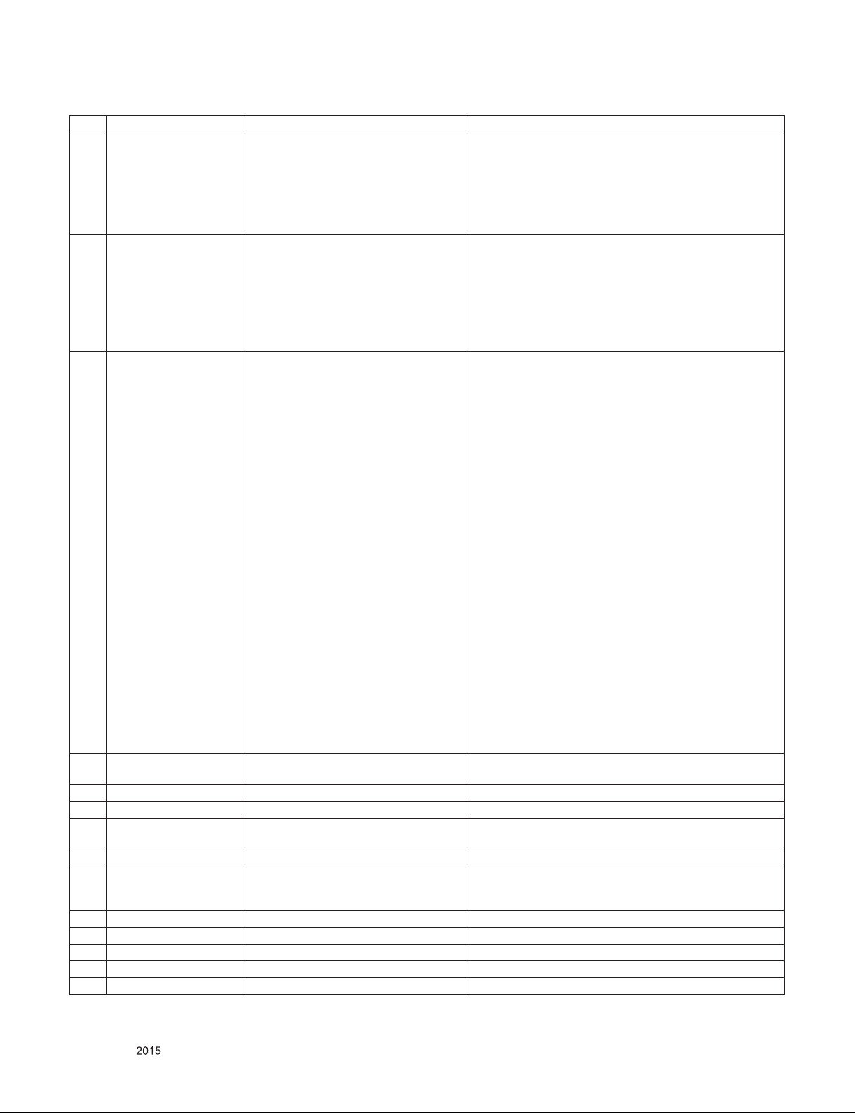
No. Item Specication Remarks
1) Digital TV
- DVB-T/T2
- DVB-C
2 Broadcasting system
3 Program coverage
4 Receiving system
- DVB-S/S2
2) Analogue TV
- PAL/SECAM B/G/I/D/K
- SECAM L/L’
1) Digital TV
- VHF, UHF
- C-Band, Ku-Band
2) Analogue TV
- VHF : E2 to E12
- UHF : E21 to E69
- CATV : S1 to S20
- HYPER : S21 to S47
Analog : Upper Heterodyne
Digital : COFDM, QAM
► DVB-T
- Guard Interval(Bitrate_Mbit/s)
1/4, 1/8, 1/16, 1/32
- Modulation : Code Rate
QPSK : 1/2, 2/3, 3/4, 5/6, 7/8
16-QAM : 1/2, 2/3, 3/4, 5/6, 7/8
64-QAM : 1/2, 2/3, 3/4, 5/6, 7/8
► DVB-T2 (Model : *L*V*-Z* (T2 only Model))
- Guard Interval(Bitrate_Mbit/s)
1/4, 1/8, 1/16, 1/32, 1/128, 19/128, 19/256,
- Modulation : Code Rate
QPSK : 1/2, 2/5, 2/3, 3/4, 5/6
16-QAM : 1/2, 2/5, 2/3, 3/4, 5/6
64-QAM : 1/2, 2/5, 2/3, 3/4, 5/6
256-QAM : 1/2, 2/5, 2/3, 3/4, 5/6
► DVB-C
- Symbolrate : 4.0Msymbols/s to 7.2Msymbols/s
- Modulation : 16QAM, 64-QAM, 128-QAM and 256-QAM
► DVB-S/S2
- symbolrate
DVB-S2 (8PSK / QPSK) : 2 ~ 45Msymbol/s
DVB-S (QPSK) : 2 ~ 45Msymbol/s
- viterbi
DVB-S mode : 1/2, 2/3, 3/4, 5/6, 7/8
DVB-S2 mode : 1/2, 2/3, 3/4, 3/5, 4/5, 5/6, 8/9, 9/10
5 Scart (1EA) PAL, SECAM
6 Video Input RCA(1EA) PAL, SECAM, NTSC4.43 4 System : PAL, SECAM, NTSC4.43, PAL60
7 Component Input (1EA) Y/Cb/Cr, Y/Pb/Pr 480i /576i/480p/576p/720p/1080i/1080p
8 HDMI Input (4EA)
9 Audio Input (1EA) DVI Audio, AV1/AV2/Component L/R Input.
10 Head phone out (1EA)
11 SDPIF out (1EA) SPDIF out
12 USB (3EA) EMF, DivX HD, For SVC (download) JPEG, MP3, DivX HD
13 Ethernet Connect(1EA) Ethernet Connect
14 PCMCIA Card slot (1EA) PCMCIA slot
15 RS-232C(1EA) For SVC only Side, Phone type
HDMI1-DTV, HDMI2-DTV, HDMI3-DTV,
HDMI4-DTV
Antenna, AV1, AV2, Component,
HDMI1, HDMI2, HDMI3, HDMI4, USB1,
USB2, USB3
Scart Jack is Full scart and support ATV/DTV-OUT
(not support DTV Auto AV)
HDMI1: PC support(HDMI version 1.4)
Support HDCP
Only for training and service purposes
- 7 -
LGE Internal Use OnlyCopyright © LG Electronics. Inc. All rights reserved.
Page 8
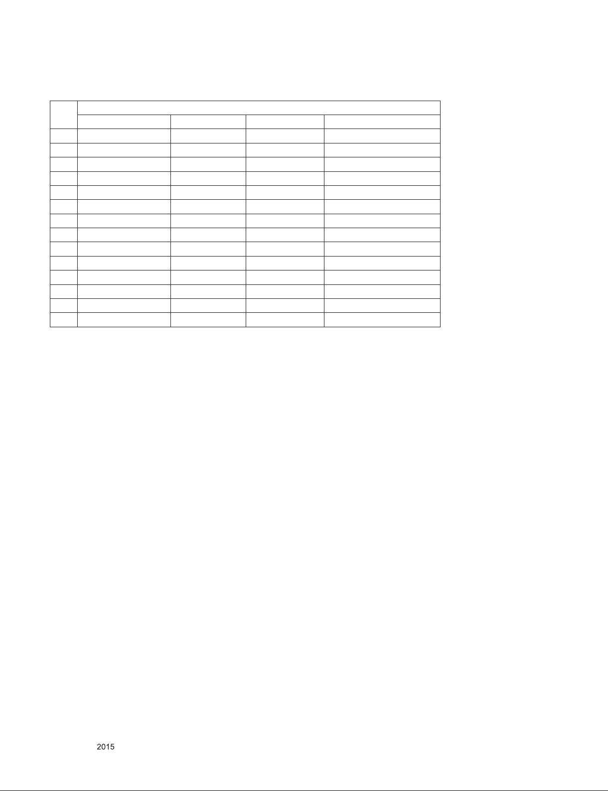
5. Component Video Input (Y, Pb, Pr)
No.
1. 720×480 15.73 60.00 SDTV, DVD 480i
2. 720×480 15.63 59.94 SDTV, DVD 480i
3. 720×480 31.47 59.94 480p
4. 720×480 31.50 60.00 480p
5. 720×576 15.625 50.00 SDTV, DVD 625 Line
6. 720×576 31.25 50.00 HDTV 576p
7. 1280×720 45.00 50.00 HDTV 720p
8. 1280×720 44.96 59.94 HDTV 720p
9. 1280×720 45.00 60.00 HDTV 720p
10. 1920×1080 31.25 50.00 HDTV 1080i
11. 1920×1080 33.75 60.00 HDTV 1080i
12. 1920×1080 33.72 59.94 HDTV 1080i
13. 1920×1080 56.250 50 HDTV 1080p
14. 1920×1080 67.5 60 HDTV 1080p
Resolution H-freq(kHz) V-freq(Hz) Pixel clock
Specication
Only for training and service purposes
- 8 -
LGE Internal Use OnlyCopyright © LG Electronics. Inc. All rights reserved.
Page 9
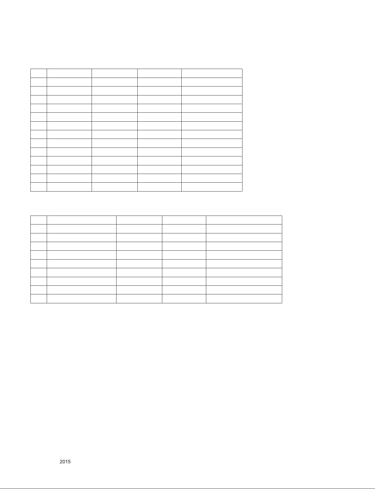
6. HDMI Input
6.1. DTV mode
No. Resolution H-freq(kHz) V-freq.(Hz) Proposed
1. 640*480 31.469 / 31.5 59.94/60 SDTV 480P
2. 720*480 31.469 / 31.5 59.94 / 60 SDTV 480P
3. 720*576 31.25 50 SDTV 576P
4. 720*576 15.625 50 SDTV 576I
5. 1280*720 37.500 50 HDTV 720P
6. 1280*720 44.96 / 45 59.94 / 60 HDTV 720P
7. 1920*1080 33.72 / 33.75 59.94 / 60 HDTV 1080I
8. 1920*1080 28.125 50.00 HDTV 1080I
9. 1920*1080 26.97 / 27 23.97 / 24 HDTV 1080P
10. 1920*1080 28.125 25 HDTV 1080P
11. 1920*1080 33.716 / 33.75 29.976 / 30.00 HDTV 1080P
12. 1920*1080 56.250 50 HDTV 1080P
13. 1920*1080 67.43 / 67.5 59.94 / 60 HDTV 1080P
6.2. PC mode
No. Resolution H-freq(kHz) V-freq.(Hz) Proposed
1 640 x 350 @70Hz 31.468 70.09 EGA
2 720 x 400 @70Hz 31.469 70.08 DOS
3 640 x 480 @60Hz 31.469 59.94 VESA(VGA)
4 800 x 600 @60Hz 37.879 60.31 VESA(SVGA)
5 1024 x 768 @60Hz 48.363 60.00 VESA(XGA)
6 1152 x 864 @60Hz 54.348 60.053 VESA
7 1280 x 1024 @60Hz 63.981 60.020 VESA(SXGA)
8 1360 x 768 @60Hz 47.712 60.015 VESA(WXGA)
9 1920 x 1080 @60Hz 67.5 60.00 WUXGA(Reduced Blanking))
Only for training and service purposes
- 9 -
LGE Internal Use OnlyCopyright © LG Electronics. Inc. All rights reserved.
Page 10
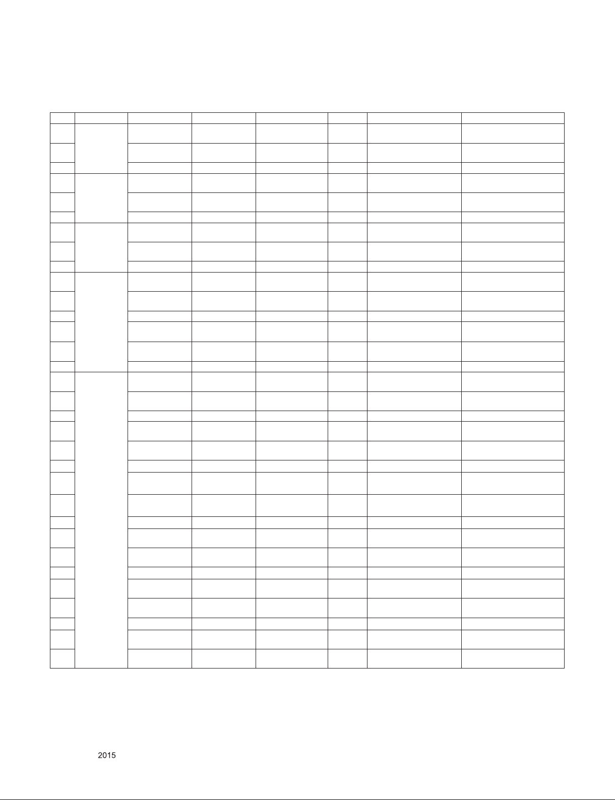
7. 3D Mode
7.1. HDMI 1.4b (3D supported mode automatically)
No. Resolution H-freq(kHz) V-freq.(Hz) Pixel clock(MHz) VIC 3D input proposed mode Proposed
1
640*480
2 62.938 / 63 59.94/ 60 50.35/50.4 1
3 31.469 / 31.5 59.94/ 60 50.35/50.4 1 Side-by-side(Full) (SDTV 480P)
4
720*480
5 62.938 / 63 59.94 / 60 54/54.06 2,3
6 31.469 / 31.5 59.94 / 60 54/54.06 2,3 Side-by-side(Full) (SDTV 480P)
7
720*576
8 62.5 50 54 17,18
9 31.25 50 54 17,18 Side-by-side(Full) (SDTV 576P)
10
11 75 50 148.5 19
12 37.5 50 148.5 19 Side-by-side(Full) (HDTV 720P)
1280*720
13 44.96 / 45 59.94 / 60 74.18/74.25 4
14 89.91 / 90 59.94 / 60 148.35/148.5 4
15 44.96 / 45 59.94 / 60 148.35/148.5 4 Side-by-side(Full) (HDTV 720P)
16
17 67.432 / 67.5 59.94 / 60 148.35/148.5 5
18 33.72 / 33.75 59.94 / 60 148.35/148.5 5 Side-by-side(Full) (HDTV 1080I)
19 28.125 50.00 74.25 20
20 56.25 50.00 148.5 20
21 28.125 50.00 148.5 20 Side-by-side(Full) (HDTV 1080I)
22 26.97 / 27 23.97 / 24 74.18/74.25 32
23 43.94 / 54 23.97 / 24 148.35/148.5 32
1920*1080
24 26.97 / 27 23.97 / 24 148.35/148.5 32 Side-by-side(Full) (HDTV 1080P)
25 28.125 25 74.25 33
26 56.25 25 148.5 33
27 28.125 25 148.5 33 Side-by-side(Full) (HDTV 1080P)
28 33.716 / 33.75 29.976 / 30.00 74.18/74.25 34
29 67.432 / 67.5 29.976 / 30.00 148.35/148.5 34
30 33.716 / 33.75 29.976 / 30.00 148.35/148.5 34 Side-by-side(Full) (HDTV 1080P)
31 56.25 50 148.5 31
32 67.43 / 67.5 59.94 / 60 148.35/148.50 16
31.469 / 31.5 59.94/ 60 25.175/25.2 1
31.469 / 31.5 59.94 / 60 27.00/27.03 2,3
31.25 50 27 17,18
37.5 50 74.25 19
33.72 / 33.75 59.94 / 60 74.18/74.25 5
Top-and-Bottom
Side-by-side(half)
Frame packing
Line alternative
Top-and-Bottom
Side-by-side(half)
Frame packing
Line alternative
Top-and-Bottom
Side-by-side(half)
Frame packing
Line alternative
Top-and-Bottom
Side-by-side(half)
Frame packing
Line alternative
Top-and-Bottom
Side-by-side(half)
Frame packing
Line alternative
Top-and-Bottom
Side-by-side(half)
Frame packing
Field alternative
Top-and-Bottom
Side-by-side(half)
Frame packing
Field alternative
Top-and-Bottom
Side-by-side(half)
Frame packing
Line alternative
Top-and-Bottom
Side-by-side(half)
Frame packing
Line alternative
Top-and-Bottom
Side-by-side(half)
Frame packing
Line alternative
Top-and-Bottom
Side-by-side(half)
Top-and-Bottom
Side-by-side(half)
Secondary(SDTV 480P)
Secondary(SDTV 480P)
Secondary(SDTV 480P)
(SDTV 480P)
Secondary(SDTV 480P)
Secondary(SDTV 480P)
Secondary(SDTV 480P)
(SDTV 480P)
Secondary(SDTV 576P)
Secondary(SDTV 576P)
Secondary(SDTV 576P)
(SDTV 576P)
Primary(HDTV 720P)
Primary(HDTV 720P)
Primary(HDTV 720P)
(HDTV 720P)
Primary(HDTV 720P)
Primary(HDTV 720P)
Primary(HDTV 720P)
(HDTV 720P)
Secondary(HDTV 1080I)
Primary(HDTV 1080I)
Primary(HDTV 1080I)
(HDTV 1080I)
Secondary(HDTV 1080I)
Primary(HDTV 1080I)
Primary(HDTV 1080I)
(HDTV 1080I)
Primary(HDTV 1080P)
Primary(HDTV 1080P)
Primary(HDTV 1080P)
(HDTV 1080P)
Secondary(HDTV 1080P)
Secondary(HDTV 1080P)
Secondary(HDTV 1080P)
(HDTV 1080P)
Primary(HDTV 1080P)
Secondary(HDTV 1080P)
Primary(HDTV 1080P)
(HDTV 1080P)
Primary(HDTV 1080P)
Secondary(HDTV 1080P)
Primary(HDTV 1080P)
Secondary(HDTV 1080P)
Only for training and service purposes
- 10 -
LGE Internal Use OnlyCopyright © LG Electronics. Inc. All rights reserved.
Page 11
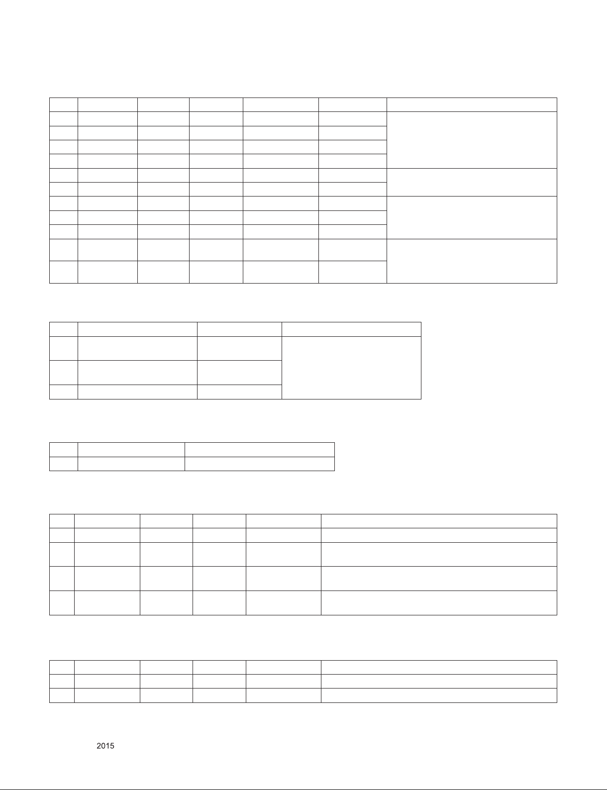
7.2. HDMI Input(1.3)
No. Resolution H-freq(kHz) V-freq.(kHz) Pixel clock(MHz) Proposed 3D input proposed mode
1 720*480 31.5 60 27.03 SDTV 480P
2 720*576 31.25 50 27 SDTV 576P
3 1280*720 45.00 60.00 74.25 HDTV 720P
4 1280*720 37.500 50 74.25 HDTV 720P
5 1920*1080 33.75 60.00 74.25 HDTV 1080I
6 1920*1080 28.125 50.00 74.25 HDTV 1080I
7 1920*1080 27.00 24.00 74.25 HDTV 1080P
8 1920*1080 28.12 25 74.25 HDTV 1080P
9 1920*1080 33.75 30.00 74.25 HDTV 1080P
10 1920*1080 67.50 60.00 148.5 HDTV 1080P
11 1920*1080 56.250 50 148.5 HDTV 1080P
2D to 3D, Side by Side(Half), Top & Bottom, Checker Board, Frame Sequential,
Row Interleaving, Column Interleaving
2D to 3D, Side by Side(Half), Top & Bottom
2D to 3D, Side by Side(Half), Top & Bottom, Checker Board, Row Interleaving,
Column Interleaving
2D to 3D, Side by Side(Half), Top &
Bottom, Checker Board, Single Frame
Sequential, Row Interleaving, Column
Interleaving
7.3. RF Input(3D supported mode manually)
No. Resolution Proposed 3D input proposed mode
1 HD (DTV)
2 SD (DTV)
3 SD (ATV : CVBS / SCART) -
1080I
720P
576P
576I
2D to 3D
Side by Side(Half)
Top & Bottom
7.4. RF Input (3D supported mode automatically)
No. Signal 3D input proposed mode
1 Frame Compatible Side by Side(Half), Top & Bottom
7.5. USB, DLNA (Movie) Input (3D supported mode manually)
No. Resolution H-freq(kHz) V-freq.(Hz) Pixel clock(MHz) 3D input proposed mode
1 Under 704x480 - - - 2D to 3D
Over 704x480
2
interlaced
Over 704x480
3
progressive
Over 704x480
4
progressive
- - - 2D to 3D, Side by Side(Half), Top & Bottom
- 50 / 60 -
- others -
2D to 3D, Side by Side(Half), Top & Bottom, Checker Board,
Row Interleaving, Column Interleaving, Frame Sequential
2D to 3D, Side by Side(Half), Top & Bottom, Checker Board,
Row Interleaving, Column Interleaving
7.6. USB, DLNA (Photo) Input (3D supported mode manually)
No. Resolution H-freq(kHz) V-freq.(Hz) Pixel clock(MHz) 3D input proposed mode
1 Under 320x240 - - - 2D to 3D
2 Over 320x240 - - - 2D to 3D, Side by Side(Half), Top & Bottom
Only for training and service purposes
- 11 -
LGE Internal Use OnlyCopyright © LG Electronics. Inc. All rights reserved.
Page 12
* USB, DNLA Input (3D supported mode automatically)
No. Resolution H-freq(kHz) V-freq.(Hz) Pixel clock(MHz) 3D input proposed mode
1 1080P 33.75 30 -
Side by Side(Half), Top & Bottom, Checker Board,
MPO(Photo), JPS(Photo)
7.7. HDMI-PC Input (3D supported mode manually)
No. Resolution H-freq(kHz) V-freq.(Hz) Pixel clock(MHz) 3D input proposed mode Proposed
1 1024*768 48.36 60 65
2 1360*768 47.71 60 85.5
2D to 3D, Side by Side(half)
Top & Bottom
HDTV 768P
2D to 3D, Side by Side(half), Top
3 1920*1080 67.500 60 148.50
& Bottom, Checker Board, Single
Frame Sequential, Row Interleaving,
HDTV 1080P
Column Interleaving
640*350
4 Others - - -
2D to 3D,
Side by Side(half)
Top & Bottom
720*400
640*480
800*600
1152*864
7.8. Component Input(3D) (3D supported mode manually)
No. Resolution H-freq(kHz) V-freq.(Hz) Pixel clock Proposed 3D input proposed mode
1 1280*720 45.00 60.00 74.25 HDTV 720P
2 1280*720 37.500 50 74.25 HDTV 720P
3 1920*1080 33.75 60.00 74.25 HDTV 1080I
4 1920*1080 28.125 50.00 74.25 HDTV 1080I
5 1920*1080 27.00 24.00 74.25 HDTV 1080P
6 1920*1080 28.12 25 74.25 HDTV 1080P
7 1920*1080 33.75 30.00 74.25 HDTV 1080P
8 1920*1080 67.50 60.00 148.5 HDTV 1080P
9 1920*1080 56.250 50 148.5 HDTV 1080P
10 Others - - - SDTV
2D to 3D, Side by Side(Half), Top & Bottom
7.9. Miracast, Widi (3D supported mode manually)
No. Resolution H-freq(kHz) V-freq.(Hz) Pixel clock(MHz) 3D input proposed mode
1 1024X768p - 30 / 60 -
2D to 3D, Side by Side(Half), Top & Bottom2. 1280x720p - 30 / 60 -
3 1920X1080p 30 / 60
4 Others - 2D to 3D
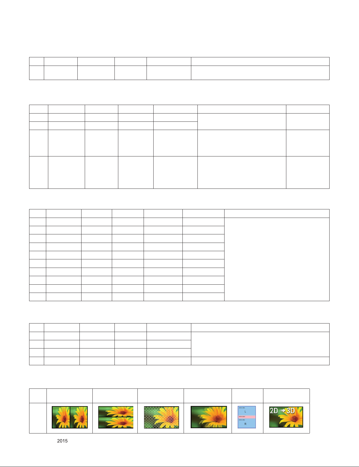
7.10. 3D Input mode
No. Side by Side Top & Bottom Checker board
1
ii.
Only for training and service purposes
iii.
iv.
- 12 -
Single Frame
Sequential
v.
Frame
Packing
vi.
2D to 3D
LGE Internal Use OnlyCopyright © LG Electronics. Inc. All rights reserved.
Page 13
ADJUSTMENT INSTRUCTION
1. Application Range
This specification sheet is applied to ED42D Chassis applied
OLED TV all models manufactured in TV factory.
2. Designation
(1) Because this is not a hot chassis, it is not necessary to
use an isolation transformer. However, the use of isolation
transformer will help protect test instrument.
(2) Adjustment must be done in the correct order.
(3) The adjustment must be performed in the circumstance of
25 °C ± 5 °C of temperature and 65 % ± 10 % of relative
humidity if there is no specific designation.
(4) The input voltage of the receiver must keep AC 100-240
V~, 50/60 Hz.
(5) The receiver must be operated for about 5 minutes prior to
the adjustment when module is in the circumstance of over
15 °C.
In case of keeping module is in the circumstance of 0 °C, it
should be placed in the circumstance of above 15 °C for 2
hours.
In case of keeping module is in the circumstance of below
-20 °C, it should be placed in the circumstance of above 15
°C for 3 hours.
[Caution]
When still image is displayed for a period of 20 minutes or
longer (Especially where W/B scale is strong. Digital pattern
13ch and/or Cross hatch pattern 09ch), there can some
afterimage in the black level area.
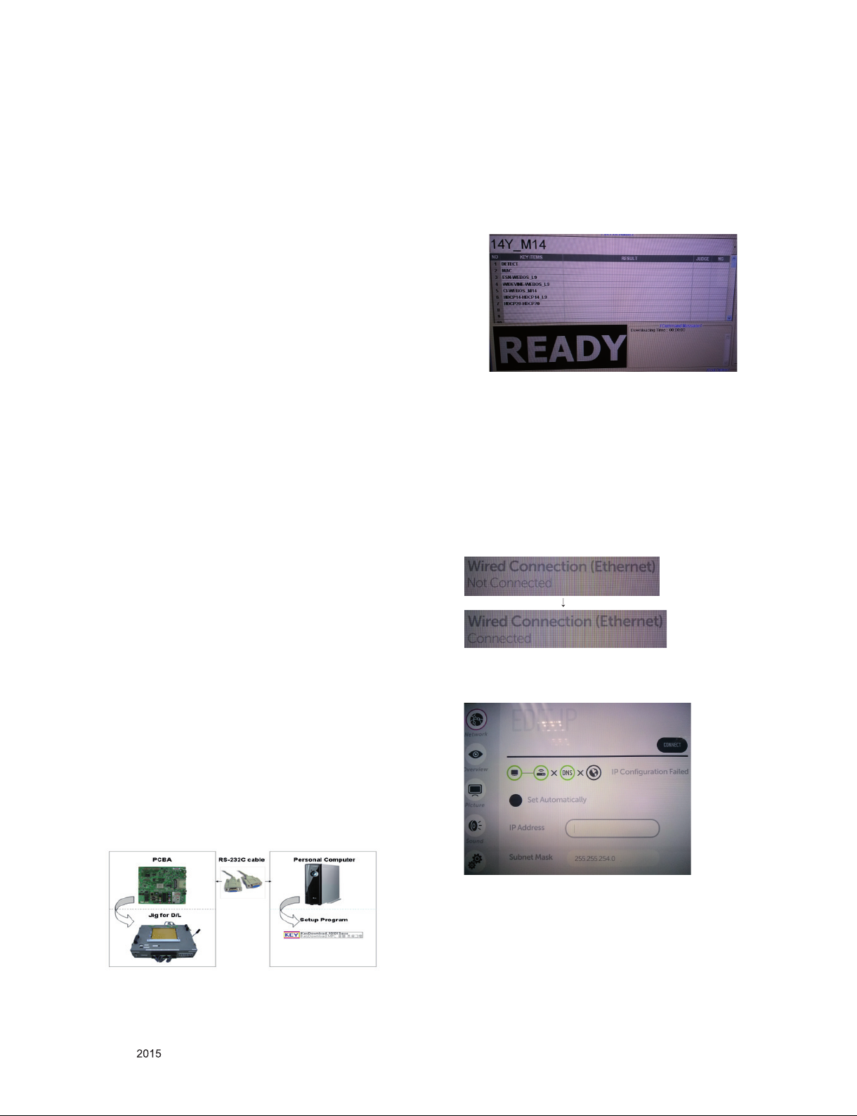
(3) Download process
1) Select the download items.
2) Mode check: Online Only
3) Check the test process
: DETECT → MAC_WRITE → ESN → WIDEVINE_
WRITE → CI+ → HDCP14 → HDCP20
4) Play: START
5) Check of result: Ready, Test, OK or NG
(4) Inspection
- In INSTART menu, check these keys.
3.3. LAN port Inspection
3.3.1. Equipment and Condition
Each other connection to LAN Port of IP Hub and Jig.
3.3.2. LAN inspection solution
▪ LAN Port connection with PCB
▪ Setting automatic IP
3. MAIN PCBA Adjustments
3.1. ADC Calibration
- An ADC calibration is not necessary because MAIN SoC
(LGE1311) is already calibrated from IC Maker.
3.2. MAC Address, ESN, Widevine, HDCP2.0
key download
* CI+ key : only for ED42D(55EC930V-ZA)
(1) Equipment & Condition
1) Play file: keydownload.exe
(2) Communication Port connection
1) Key Write: Com 1,2,3,4 and 115200 (Baudrate)
2) Barcode: Com 1,2,3,4 and 9600 (Baudrate)
3) Connect
: PCBA Jig → RS-232C Port == PC → RS-232C Port
▪ If you want manual connection, enter Network connection at
MENU Mode of TV. Press Start connection key, then
Network will be connected.
Only for training and service purposes
- 13 -
LGE Internal Use OnlyCopyright © LG Electronics. Inc. All rights reserved.
Page 14
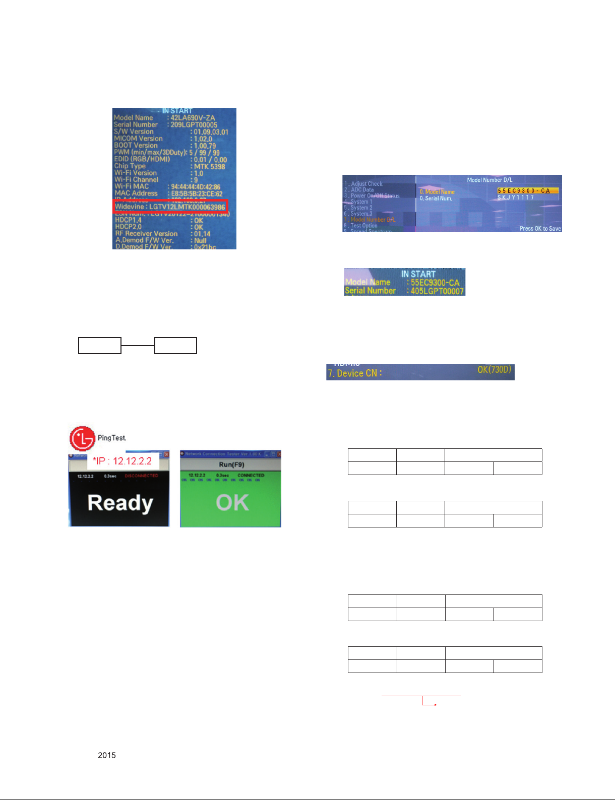
3.2.3. Widevine, ESN, HDCP1.4, HDCP2.0 key inspection
- Confirm key input data at the "IN START" MENU Mode.
3.3. LAN PORT INSPECTION(PING TEST)
3.3.1. Equipment setting
(1) Play the LAN Port Test PROGRAM.
(2) Input IP set up for an inspection to Test Program.
- IP Number : 12.12.2.2
Connect: SET → LAN Port == PC → LAN Port
SET PC
3.3.2. LAN PORT inspection(PING TEST)
(1) Play the LAN Port Test Program.
(2) Connect each other LAN Port Jack.
(3) Play Test (F9) button and confirm OK Message.
(4) Remove LAN cable.
3.4. Model name & Serial number Download
3.4.1. Model name & Serial number D/L
▪ Press "P-ONLY" key of service remote control.
(Baud rate : 115200 bps)
▪ Connect RS-232C Signal to USB Cable to USB.
▪ Write Serial number by use USB port.
▪ Must check the serial number at Instart menu.
3.4.2. Method & notice
(1) Serial number D/L is using of scan equipment.
(2) Setting of scan equipment operated by Manufacturing
Technology Group.
(3) Serial number D/L must be conformed when it is produced
in production line, because serial number D/L is mandatory
by D-book 4.0.
* Manual Download (Model Name and Serial Number)
If the TV set is downloaded by OTA or service man, sometimes
model name or serial number is initialized.(Not always)
It is impossible to download by bar code scan, so It need
Manual download.
1) Press the "Instart" key of Adjustment remote control.
2) Go to the menu "7.Model Number D/L" like below photo.
3) Input the Factory model name or Serial number
[Example]
4) Check the model name Instart menu. → Factory name
displayed.
[Example]
3.5. CI+ Key checking method
* Only for ED42D(55EC930V-ZA)
Check whether the key was downloaded or not at ‘In Start’
menu. (Refer to below).
Check the Download to CI+ Key value in LGset.
3.5.1. Check the method of CI+ Key value
(1) Check the method on Instart menu
(2) Check the method of RS232C Command
1) Into the main ass’y mode(RS232: aa 00 00)
CMD 1 CMD 2 Data 0
A A 0 0
2) Check the key download for transmitted command
(RS232: ci 00 10)
CMD 1 CMD 2 Data 0
C I 1 0
3) Result value
- Normally status for download : OKx
- Abnormally status for download : NGx
3.5.2. Check the method of CI+ key value(RS232)
1) Into the main ass’y mode(RS232: aa 00 00)
CMD 1 CMD 2 Data 0
A A 0 0
2) Check the mothed of CI+ key by command
(RS232: ci 00 20)
CMD 1 CMD 2 Data 0
C I 2 0
3) Result value
i 01 OK 1d1852d21c1ed5dcx
CI+ Key Value
Only for training and service purposes
- 14 -
LGE Internal Use OnlyCopyright © LG Electronics. Inc. All rights reserved.
Page 15
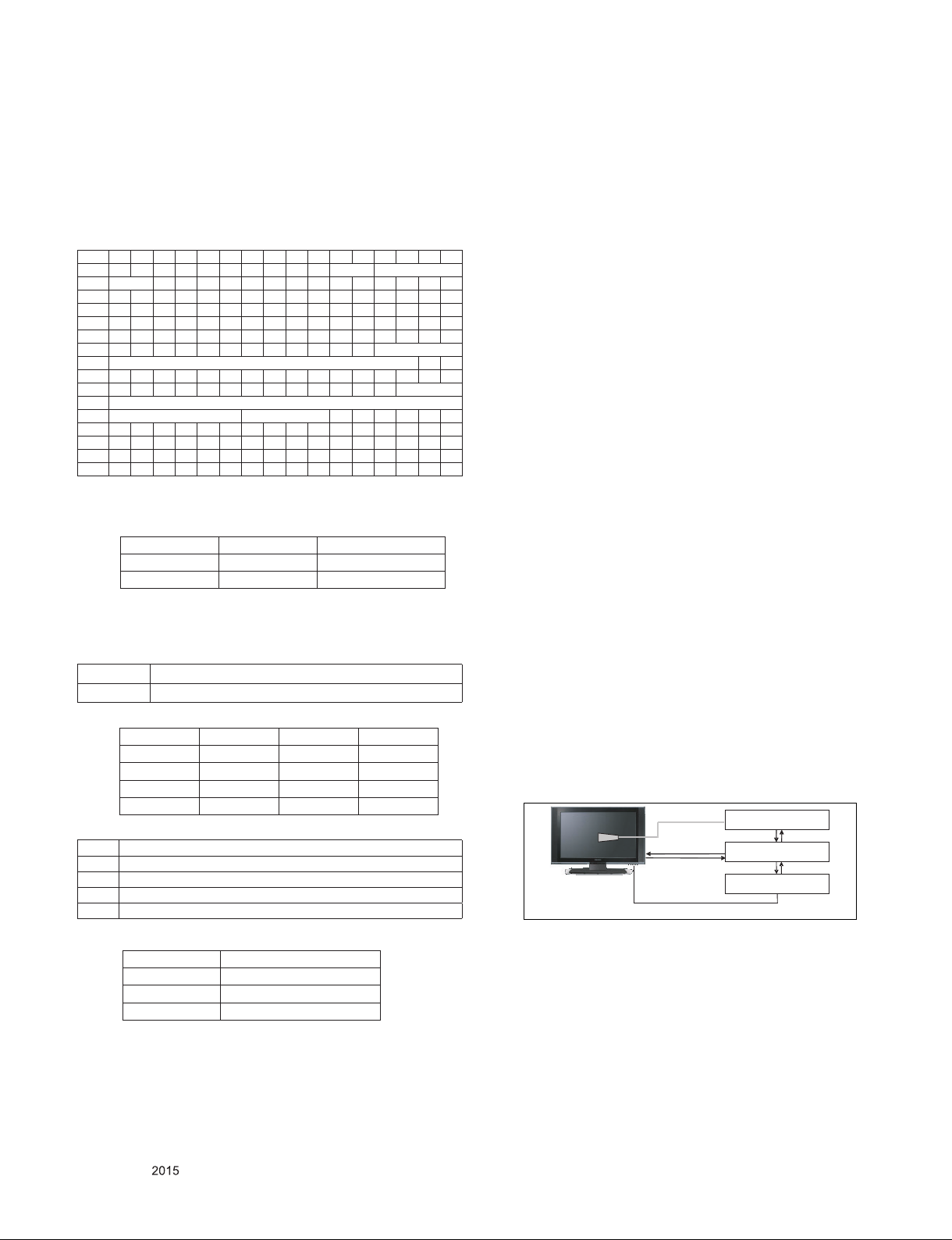
4. Manual Adjustment
4.1. ADC adjustment need not. Because of
OTP(Auto ADC adjustment)
4.2. EDID DATA
HDMI EDID DATA 3D
0 1 2 3 4 5 6 7 8 9 A B C D E F
0 00 FF FF FF FF FF FF 00 1E 6D
ⓒ
10
20 0F 50 54 A1 8 00 31 40 45 40 61 40 71 40 81 80
30 01 01 01 01 01 01 02 3A 80 18 71 38 2D 40 58 2C
40 45 00 40 84 63 00 00 1E 66 21 50 B0 51 00 1B 30
50 40 70 36 00 40 84 63 00 00 1E 00 00 00 FD 00 3A
60 3E 1E 53 10 00 0A 20 20 20 20 20 20
70
80 02 03 3A F1 4E 10 9F 04 13 05 14 03 02 12 20 21
90 22 15 01 29 3D 06 C0 15 07 50 09 57 07
A0
B0
C0 2D 40 58 2C 45 00 40 84 63 00 00 1E 01 1D 80 18
D0 71 1C 16 20 58 2C 25 00 40 84 63 00 00 9E 01 1D
E0 00 72 51 D0 1E 20 6E 28 55 00 40 84 63 00 00 1E
F0 00 00 00 00 00 00 00 00 00 00 00 00 00 00 00
01 03 80 A0 5A 78 0A EE 91 A3 54 4C 99 26
ⓓ
ⓕ
ⓕ ⓖ
- HDMI1 ~ HDMI4
- In the data of EDID, bellows may be different by Input mode.
ⓐ Product ID
HEX EDID Table DDC Function
0001 0100 Analog
0001 0100 Digital
ⓑ Serial No: Controlled on production line.
ⓒ Month, Year: Controlled on production line:
ex) Monthly : ‘01’ → ‘01’, Year : ‘2015’ → ‘19’
ⓓ Model Name(Hex): LGTV
Chassis MODEL NAME(HEX)
ED42D 00 00 00 FC 00 4C 47 20 54 56 0A 20 20 20 20 20 20 20
ⓔ Checksum(LG TV): Changeable by total EDID data.
Input ⓔ1 ⓔ2 ⓔ3
HDMI1 E7 85 X
HDMI2 E7 75 X
HDMI3 E7 65 X
HDMI4 E7 55 X
ⓕ Vendor Specific(HDMI)
INPUT MODEL NAME(HEX)
HDMI1 78 03 0C 00 10 00 B8 2D 20 C0 0E 01 4F 00 FE 08 10 06 10 18 10 28 10 38 10
HDMI2 78 03 0C 00 20 00 B8 2D 20 C0 0E 01 4F 00 FE 08 10 06 10 18 10 28 10 38 10
HDMI3 78 03 0C 00 30 00 B8 2D 20 C0 0E 01 4F 00 FE 08 10 06 10 18 10 28 10 38 10
HDMI4 78 03 0C 00 40 00 B8 2D 20 C0 0E 01 4F 00 FE 08 10 06 10 18 10 28 10 38 10
ⓐ ⓑ
ⓓ
ⓔ1
01
ⓕ
02 3A 80 18 71 38
ⓔ2
5. White Balance Adjustment
5.1. Overview
5.1.1. W/B adj. Objective & How-it-works
(1) Objective: To reduce each Panel's W/B deviation
(2) How-it-works : When R/G/B gain in the OSD is at 192, it
means the panel is at its Full Dynamic Range. In order to
prevent saturation of Full Dynamic range and data, one of
R/G/B is fixed at 192, and the other two is lowered to find
the desired value.
(3) Adjustment condition : normal temperature
1) Surrounding Temperature : 25 °C ± 5 °C
2) Surrounding Humidity : 20 % ~ 80 %
3) Surrounding Humidity: 20% ~ 80%
4) Before White balance adjustment, Keep power on
status, don’t power off
5.1.2. Adj. condition and cautionary items
(1) Lighting condition in surrounding area surrounding lighting
should be lower 10 lux. Try to isolate adj. area into dark
surrounding.
(2) Probe location: Color Analyzer(CA-210) probe should be
within 10 cm and perpendicular of the module surface
(80°~ 100°).
(3) Aging time
1) After Aging Start, Keep the Power ON status during 5
Minutes.
2) In case of LED, Back-light on should be checked using
no signal or Full-white pattern.
5.2. Equipment
(1) Color Analyzer: CA-210 (NCG: CH 9 / WCG: CH12 / LED:
CH14 / OLED : CH : 17)
(2) Adjustment Computer(During auto adj., RS-232C protocol
is needed)
(3) Adjustment Remote control
(4) Video Signal Generator MSPG-925F 720p/204-Gray
(Model: 217, Pattern: 49)
▪ Color Analyzer Matrix should be calibrated using CS-1000.
5.3. Equipment connection MAP
Color Analyzer
Probe
USB to RS-232C
Signal Source
* If TV internal pattern is used, not needed
* Pattern Generator
RS-232C
Computer
RS-232C
ⓖ Colorimetry Data Block(HDMI) : Not supporting XvYcc
INPUT MODEL NAME(HEX)
HDMI1 E3 05 00 00
HDMI2 E3 05 00 00
HDMI3 E3 05 00 00
Only for training and service purposes
- 15 -
LGE Internal Use OnlyCopyright © LG Electronics. Inc. All rights reserved.
Page 16
5.4. Adj. Command (Protocol)
(1) RS-232C Command used during auto-adj.
RS-232C COMMAND
CMD DATA ID
Wb 00 00 Begin White Balance adj.
Wb 00 ff
End White Balance adj.(internal pattern disappears)
(2) Adjustment Map
Command
(lower case ASCII)
CMD1 CMD2 MIN MAX
Cool
Medium
Warm
Adj. item
R Gain j g 00 C0
G Gain j h 00 C0
B Gain j i 00 C0
R Cut
G Cut
B Cut
R Gain j a 00 C0
G Gain j b 00 C0
B Gain j c 00 C0
R Cut
G Cut
B Cut
R Gain j d 00 C0
G Gain j e 00 C0
B Gain j f 00 C0
R Cut
G Cut
Explanation
Data Range
(Hex.)
Default
(Decimal)
5.6. Reference(White Balance Adj. coordinate
and color temperature)
(1) Luminance: 204 Gray, 80IRE
(2) Standard color coordinate and temperature using CS-1000
(over 26 inch)
Mode
Coordinate
x y
Temp ∆uv
Cool 0.277 0.278 11,000K -0.0030
Medium 0.286 0.289 9,300K 0.0000
Warm 0.313 0.329 6,500K +0.0030
(3) Standard color coordinate and temperature using CA-210
(CH-17)
Mode
Coordinate
x y
Temp ∆uv
Cool 0.277 ± 0.002 0.278 ± 0.002 11,000 K -0.0030
Medium 0.286 ± 0.002 0.289 ± 0.002 9,300 K 0.0000
Warm 0.313 ± 0.002 0.329 ± 0.002 6,500 K +0.0030
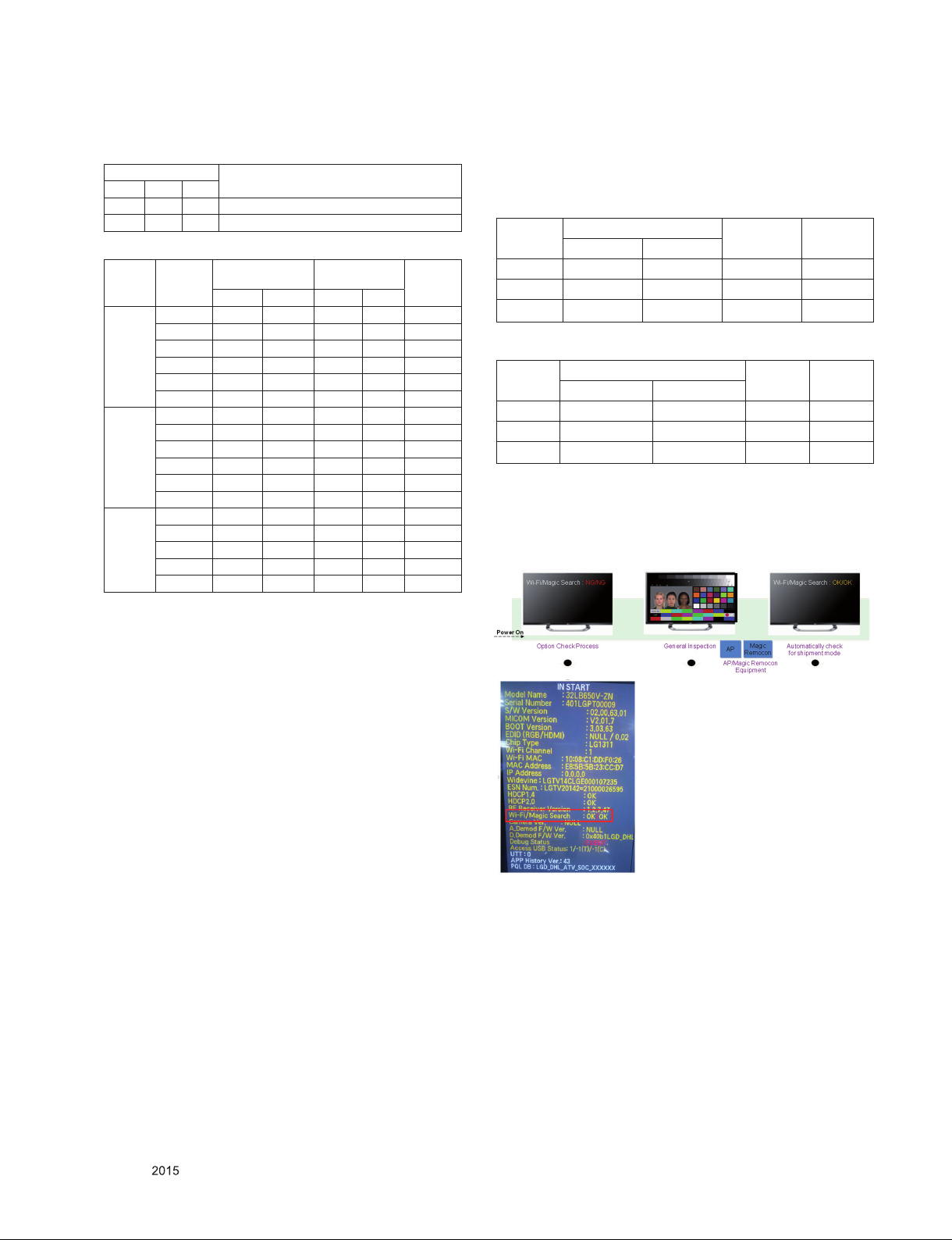
6. Magic motion remote control check
Results are automatically marked in Instart OSD after through
the AP/Magic Remote control Equipment on the line.
5.5. Adjustment method
5.5.1. Auto WB calibration
(1) Set TV in ADJ mode using P-Only key(or POWER ON key).
(2) Place optical probe on the center of the display.
- It need to check probe condition of zero calibration before
adjustment.
(3) Connect RS-232C Cable
(4) Select mode in ADJ Program and begin adjustment.
(5) When WB adjustment is completed with OK message, check
adjustment status pre-set mode.(Cool, Medium, Warm)
(6) Remove probe and RS-232C cable
▪ W/B Adj. must begin as start command “wb 00 00” , and
finish as end command “wb 00 ff”, and Adj. offset if need.
5.5.2. White balance table
(1) Cool Mode
1) Purpose : Especially G-gain fix adjust leads to the
luminance enhancement. Adjust the color temperature
to reduce the deviation of the module color temperature.
2) Principle : To adjust the white balance without the
saturation, Adjust the G gain more than 172 (If R gain or
G gain is more than 255, G gain can adjust less than
172 ) and change the others (R/B Gain).
3) Adjustment mode : mode - Cool
(2) Medium / Warm Mode
1) Purpose : Adjust the color temperature to reduce the
deviation of the module color temperature.
2) Principle : To adjust the white balance without the
saturation, Fix the one of R/G/B gain to 192 (default
data) and decrease the others.
3) Adjustment mode : Two modes - Medium / Warm
Only for training and service purposes
- 16 -
LGE Internal Use OnlyCopyright © LG Electronics. Inc. All rights reserved.
Page 17
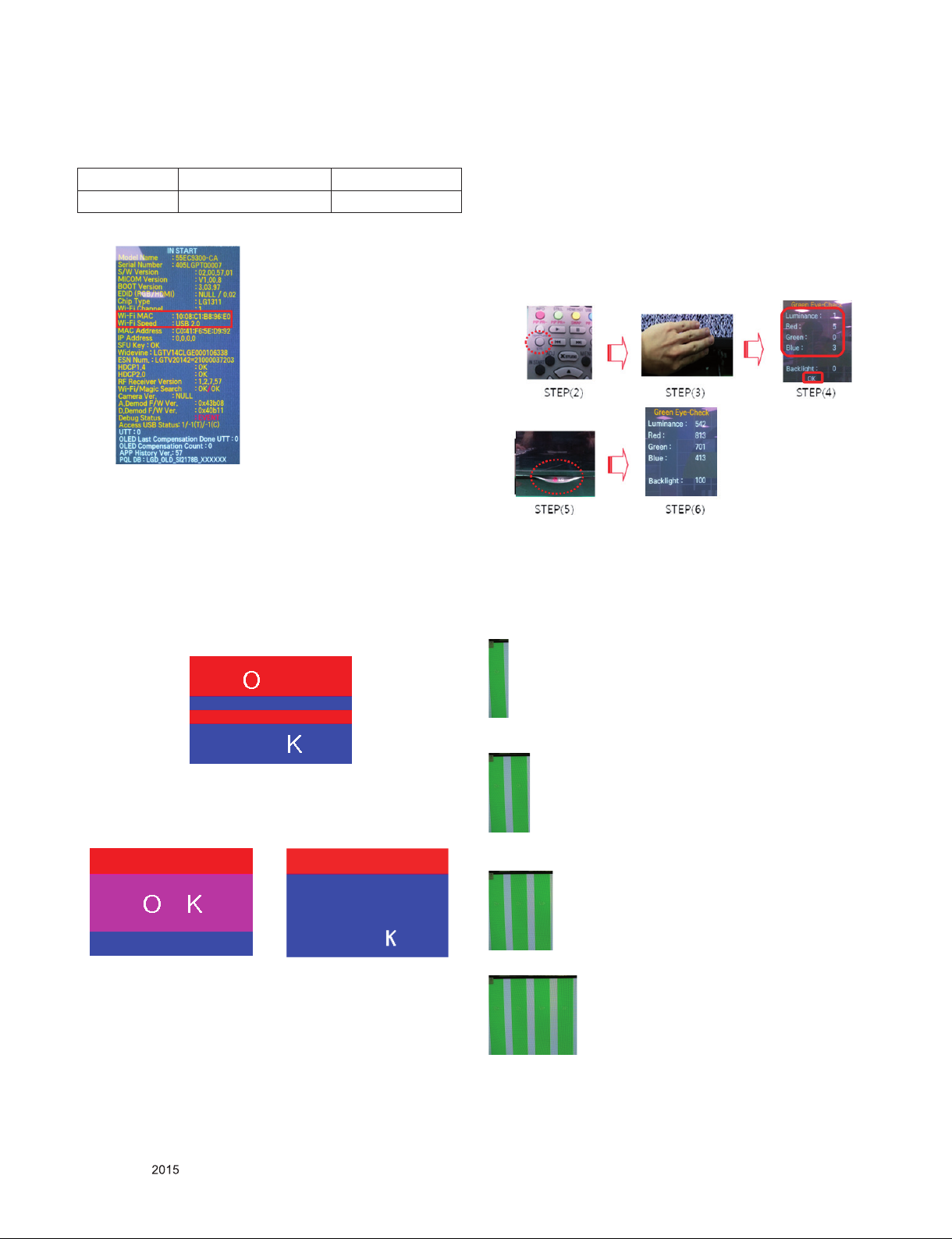
7. WIFI MAC ADDRESS CHECK
(1) Using RS232
Command Set ACK
Transmission [A][I][][Set ID][][20][Cr] [O][K][X] or [NG]
(2) Check the menu on in-start
8. 3D pattern test
8.1. Test equipment
(1) Pattern Generator MSHG-600 or MSPG-6100 (HDMI 1.4
support)
(2) Pattern: HDMI mode (model No. 872, pattern No. 83)
8.2. Test method
(1) Input 3D test signal as Fig.1.
9. Eye-Q function check
(1) Press 'EYE button' on the adjustment remote-control.
(2) Check each raw data.
(3) Cover 'Eye Q sensor' on the front of set with hand and wait
for 6 seconds.
(4) Check each data is lower than 10 and ‘OK’ message. If data
isn’t lower than 10 in 6 seconds, replace Eye Q sensor.
(5) Uncover hand from Eye Q sensor and wait for 6 seconds.
(6) Check each data increase or not. If data don’t increase,
replace Eye Q sensor.
10. Joystick function check
* Before you start a test, you must run a Power Only
Mode(Full white).
(1) Channel Up Test : Press UP KEY OF SET
<Fig.1> HDMI Mode No.872, Pattern No. 83
(2) Press ‘OK” key as a 3D input OSD is shown.
(3) Check pattern as Fig2 without 3D glasses. (3D mode
without 3D glasses)
<Fig.2> OK in 3D mode without
3D glasses
Only for training and service purposes
<Fig.3> NG in 3D mode without
3D glasses
- 17 -
(2) Channel Down Test : Press DOWN KEY OF SET
(3) Volume Up Test : Press Left KEY OF SET
(4) Volume Down Test : Press Right KEY OF SET
LGE Internal Use OnlyCopyright © LG Electronics. Inc. All rights reserved.
Page 18
(5) Enter Test : Press Enter KEY OF SET
12. AUDIO output check
12.1. AUDIO output check
(1) RF input: Mono, 1 KHz sine wave signal, 100 % Modulation
(2) CVBS, Component: 1 KHz sine wave signal (0.5 Vrms)
- Don’t need to run a test with this sequence.
For example, the sequence such as ‘Right → Up → Down →
Left → Enter’ is allowed.
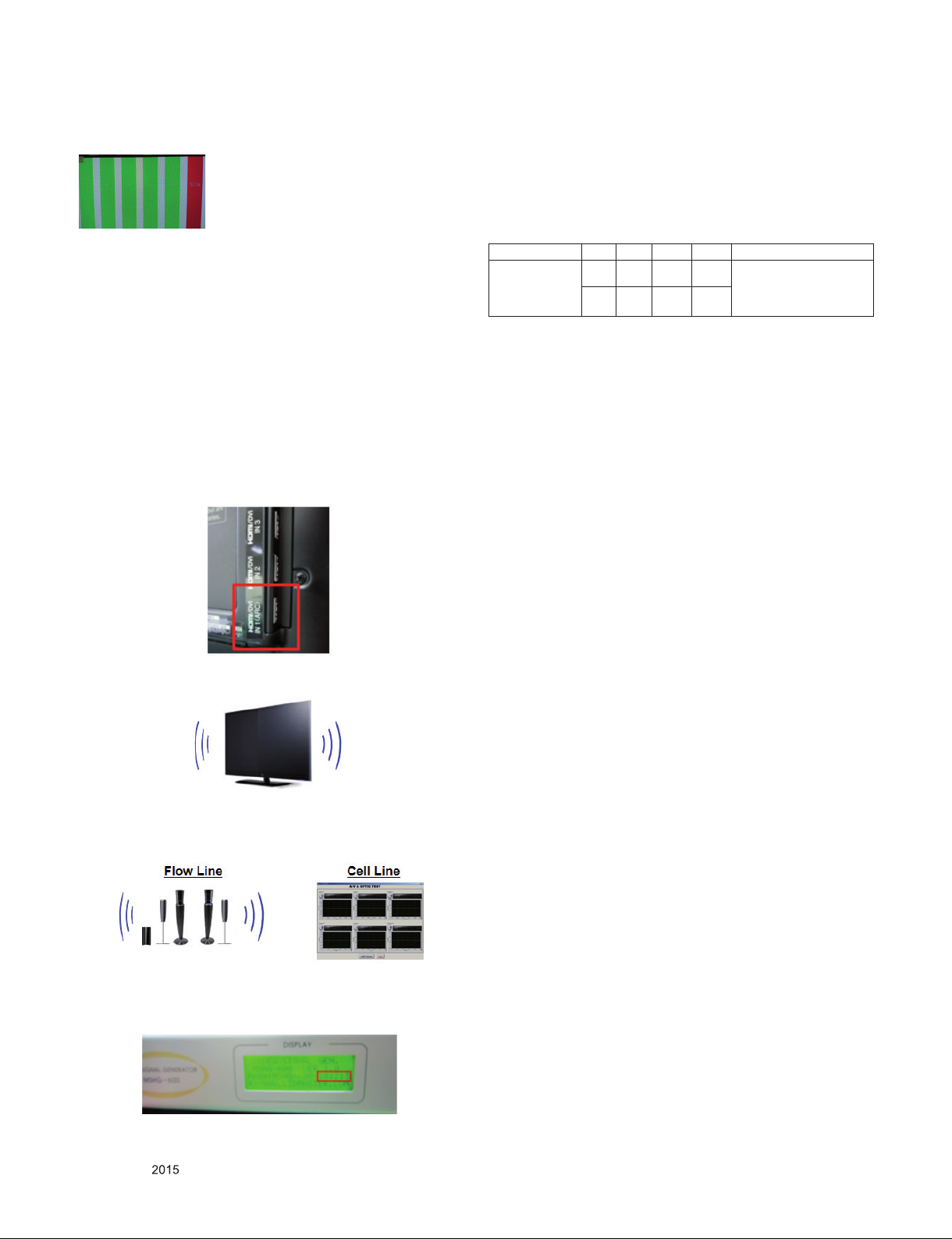
11. HDMI ARC Function Inspection
11.1. Test equipment
- Optic Receiver Speaker
- MSHG-600 (SW: 1220 ↑)
- HDMI Cable (for 1.4 version)
11.2. Test method
(1) Insert the HDMI Cable to the HDMI ARC port from the
master equipment (HDMI1)
(2) Check the sound from the TV Set
(3) Check the Sound from the Speaker or using AV & Optic
TEST program (It’s connected to MSHG-600)
12.2. Specification
Item Min Typ Max Unit Remark
Audio practical
max Output, L/R
(Distortion=10%
max Output)
9.0 10.0 12.0 W
8.5 8.9 9.9 Vrms
- Condition: EQ/AVL/Clear
Voice Off
- Speaker (8Ω Impedance)
12.3. Audio Output Inspection
- Input “Check-S KEY” of adjust remote control to inspect
speaker
(1) When you click the first, the output volume of left &right
main speakers must be 50.
(2) When you click the second, the output volume of left &right
main speakers must be 80.
(3) When you click the third, the output volume of left &right
main speakers must be 100.
(4) When you click the fourth, the output volume of left main
speaker must be 50.
(5) When you click the fifth, the output volume of right main
speaker must be 50.
13. GND and HI-POT Test
13.1. GND & HI-POT auto-check preparation
- Check the POWER cable and SIGNAL cable insertion
condition
13.2. GND & HI-POT auto-check
(1) Pallet moves in the station. (POWER CORD / AV CORD is
tightly inserted)
(2) Connect the AV JACK Tester.
(3) Controller (GWS103-4) on.
(4) GND Test (Auto)
- If Test is failed, Buzzer operates.
- If Test is passed, execute next process (Hi-pot test).
(Remove A/V CORD from A/V JACK BOX)
(5) HI-POT test (Auto)
- If Test is failed, Buzzer operates.
- If Test is passed, GOOD Lamp on and move to next
process automatically.
* Remark: Inspect in Power Only Mode and check SW version
in master equipment
Only for training and service purposes
13.3. Checkpoint
(1) Test voltage
- GND: 1.5 KV/min at 100 mA
- SIGNAL: 3 KV/min at 100 mA
(2) TEST time: 1 second
(3) TEST POINT
- GND Test = POWER CORD GND and SIGNAL CABLE
GND.
- Hi-pot Test = POWER CORD GND and LIVE &
NEUTRAL.
(4) LEAKAGE CURRENT: At 0.5 mArms
- 18 -
LGE Internal Use OnlyCopyright © LG Electronics. Inc. All rights reserved.
Page 19
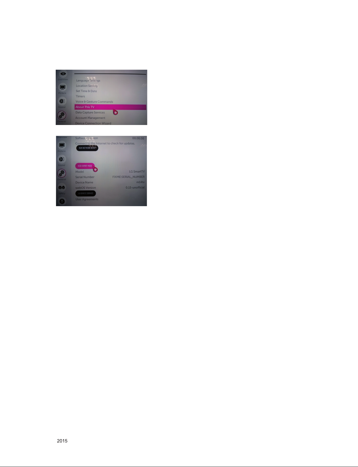
14. USB S/W download(Service only)
(1) Put the USB Stick to the USB socket.
(2) Go to General menu then enter to About This TV.
(3) Enter the USB EXPERT MODE.
(4) Updating is starting.
(5) Updating completed, the TV will restart automatically
(6) If your TV is turned on, check your updated version and
Tool option.
* If downloading version is more high than your TV have,
TV can lost all channel data. In this case, you have to
channel recover. if all channel data is cleared, you didn’t
have a DTV/ATV test on production line.
* After downloading, Tool option setting is needed again.
(1) Push "IN-START" key in service remote control.
(2) Select "Tool Option 1" and push "OK" key.
(3) Punch in the number. (Each model has their number)
Only for training and service purposes
- 19 -
LGE Internal Use OnlyCopyright © LG Electronics. Inc. All rights reserved.
Page 20
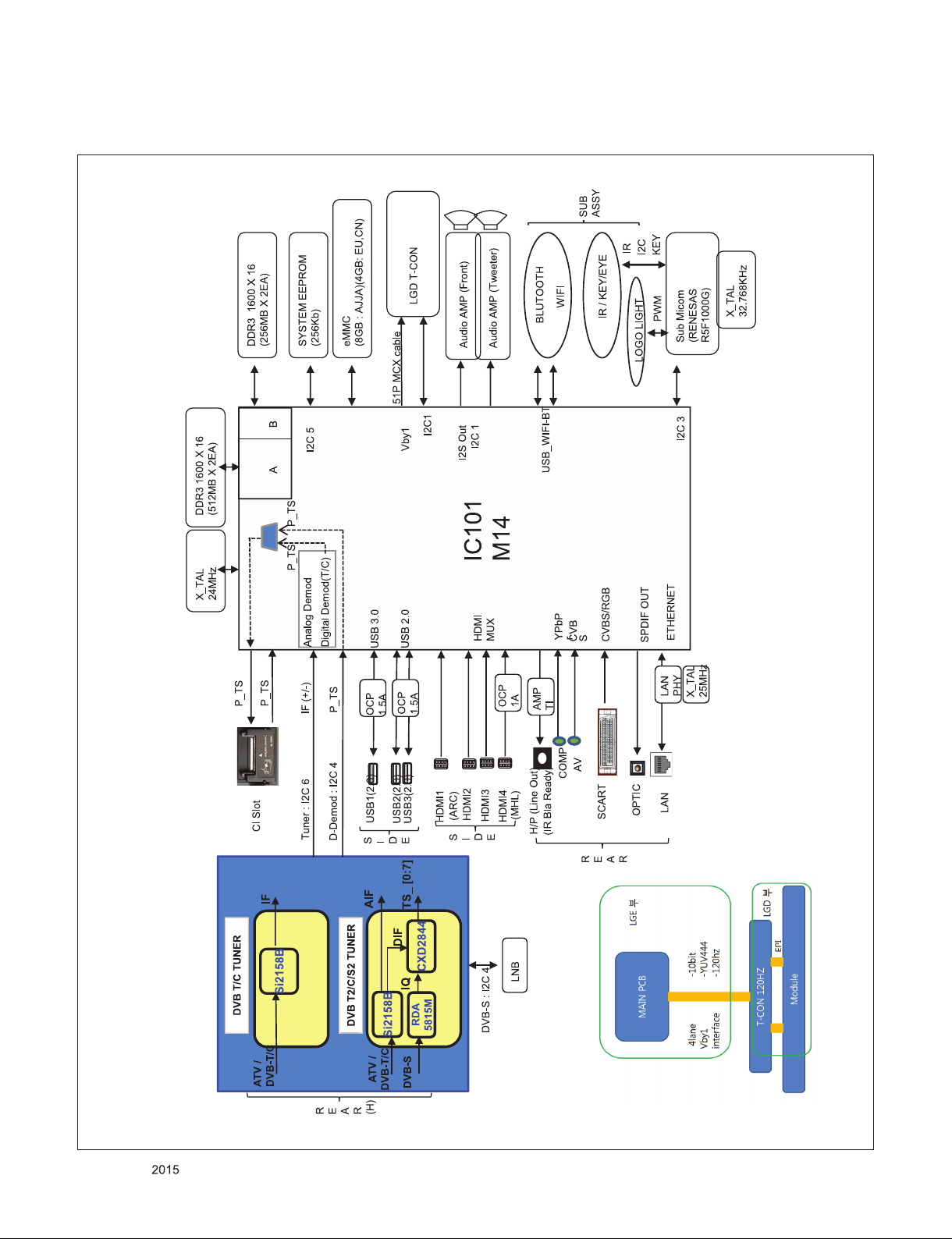
1. M14
BLOCK DIAGRAM
Only for training and service purposes
- 20 -
LGE Internal Use OnlyCopyright © LG Electronics. Inc. All rights reserved.
Page 21
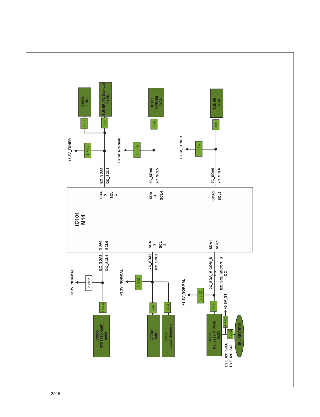
2. M14 I2C Map
Only for training and service purposes
- 21 -
LGE Internal Use OnlyCopyright © LG Electronics. Inc. All rights reserved.
Page 22
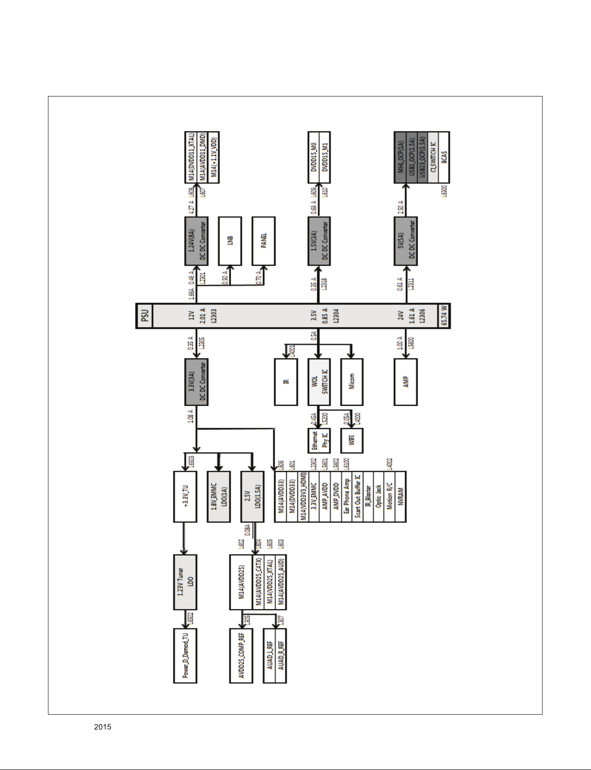
3. Power
Only for training and service purposes
- 22 -
LGE Internal Use OnlyCopyright © LG Electronics. Inc. All rights reserved.
Page 23
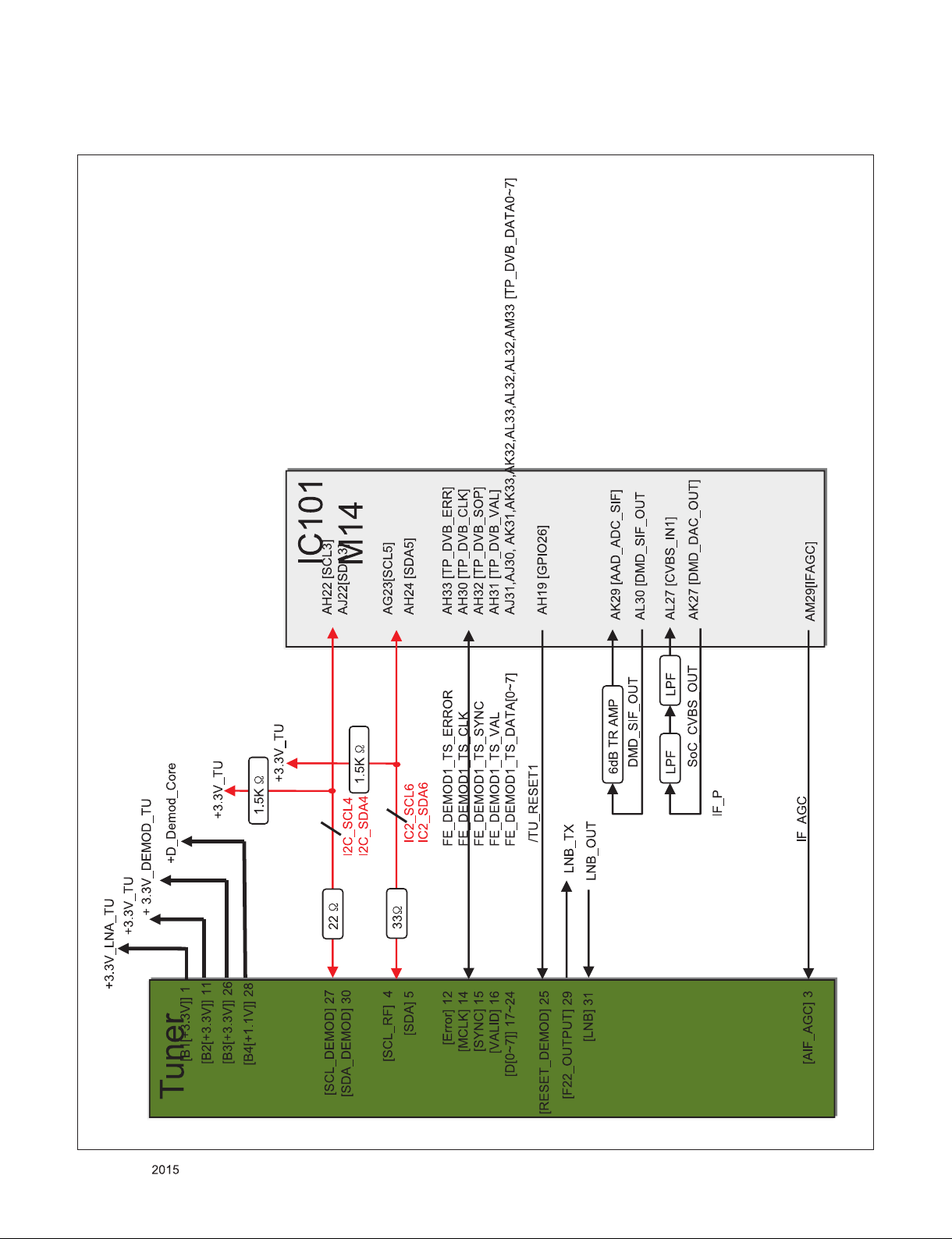
4-1. Tuner Block Diagram TDJM-G251D (EU DVB)
Only for training and service purposes
- 23 -
LGE Internal Use OnlyCopyright © LG Electronics. Inc. All rights reserved.
Page 24
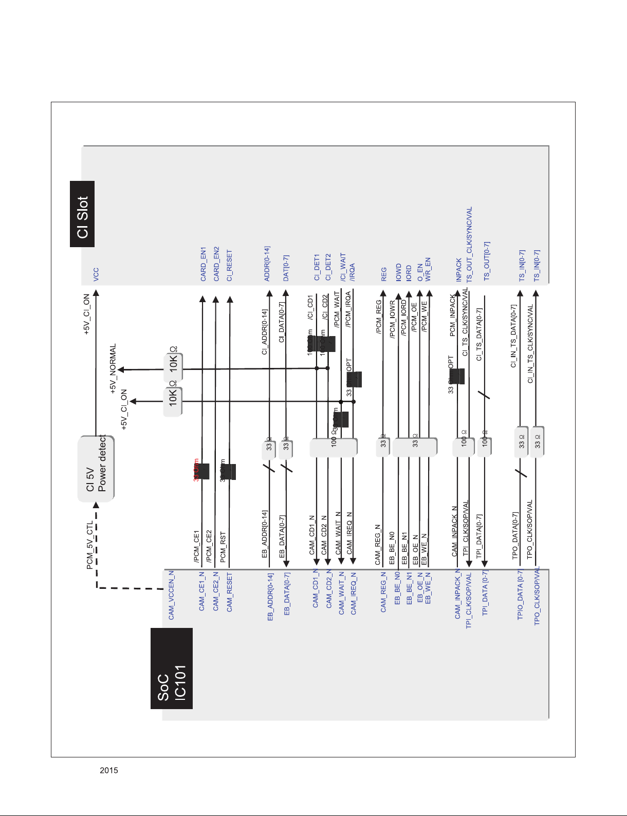
4-2. CI Block Diagram (EU, CN)
Only for training and service purposes
- 24 -
LGE Internal Use OnlyCopyright © LG Electronics. Inc. All rights reserved.
Page 25
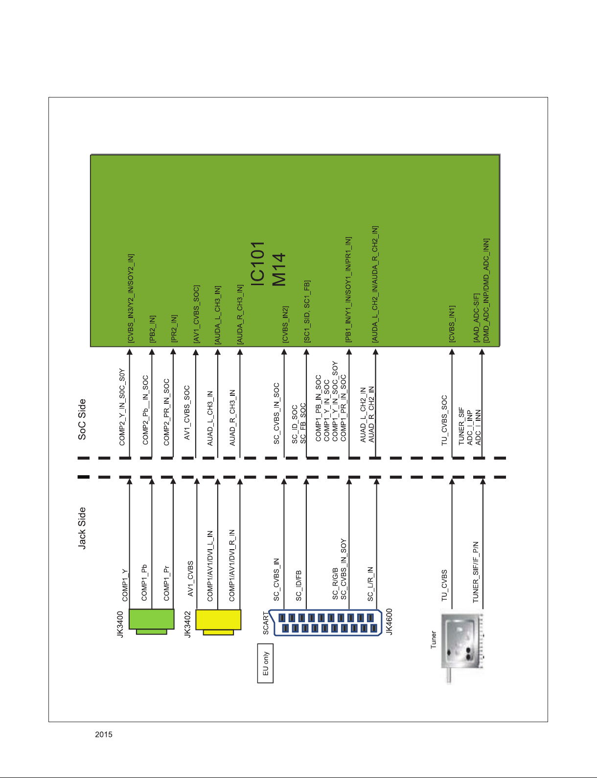
5. Video & Audio IN
Only for training and service purposes
- 25 -
LGE Internal Use OnlyCopyright © LG Electronics. Inc. All rights reserved.
Page 26
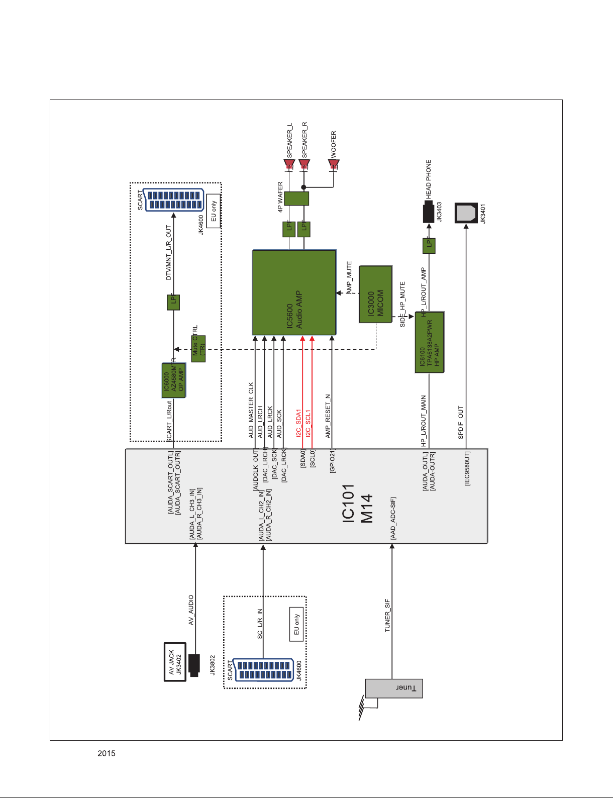
6. Audio out
Only for training and service purposes
- 26 -
LGE Internal Use OnlyCopyright © LG Electronics. Inc. All rights reserved.
Page 27
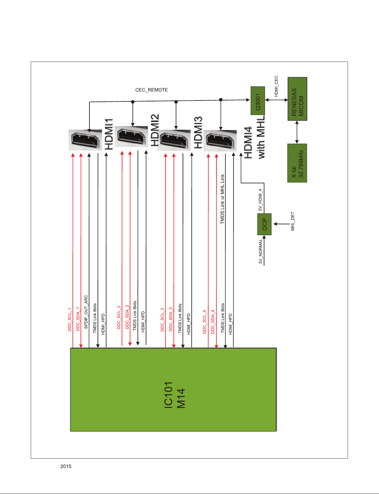
7.HDMI
Only for training and service purposes
- 27 -
LGE Internal Use OnlyCopyright © LG Electronics. Inc. All rights reserved.
Page 28
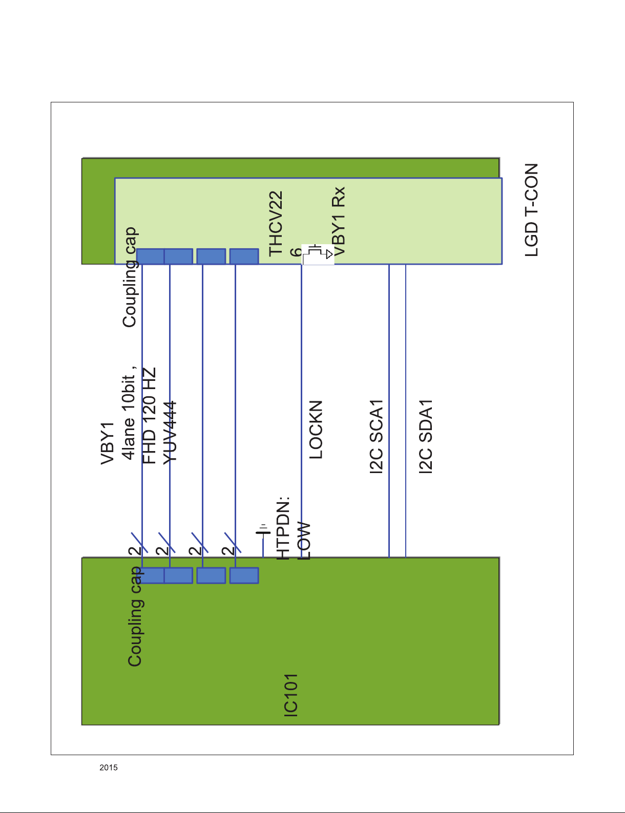
8. Panel Interface
Only for training and service purposes
- 28 -
LGE Internal Use OnlyCopyright © LG Electronics. Inc. All rights reserved.
Page 29
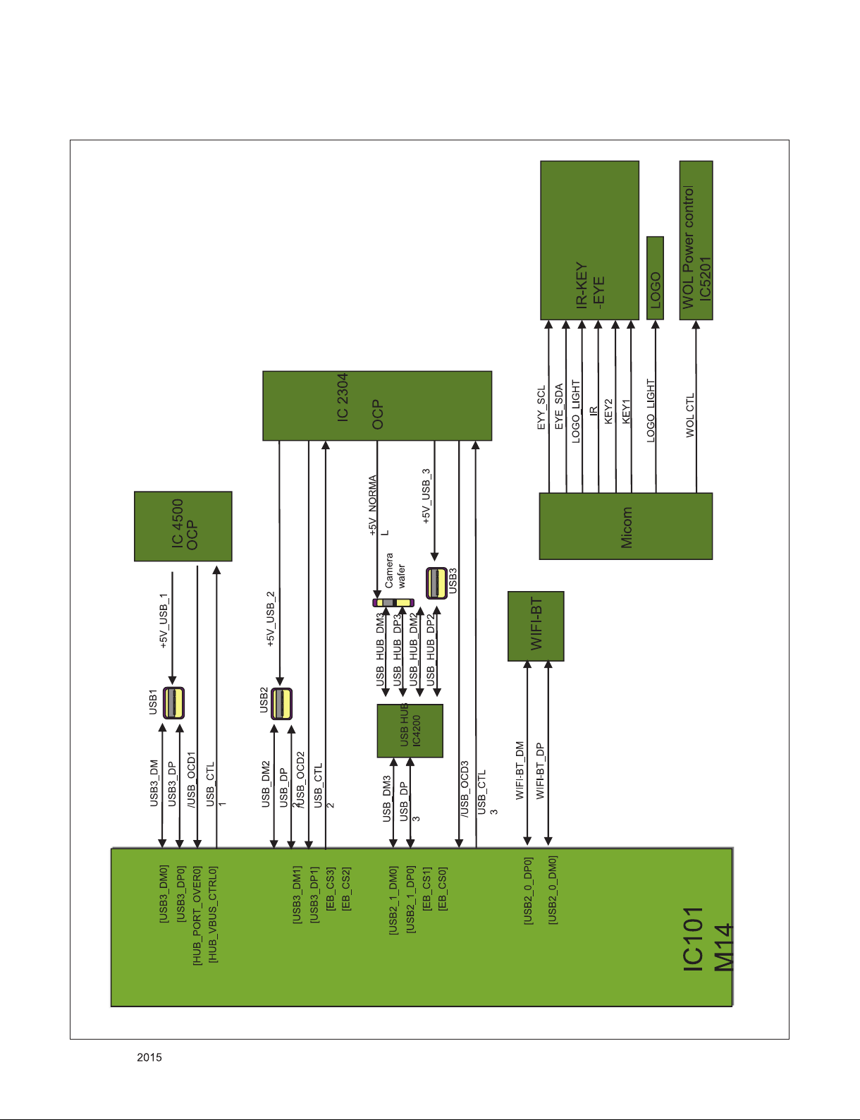
9. USB / WiFi-BT / IR-KEY-EYE
Only for training and service purposes
- 29 -
LGE Internal Use OnlyCopyright © LG Electronics. Inc. All rights reserved.
Page 30
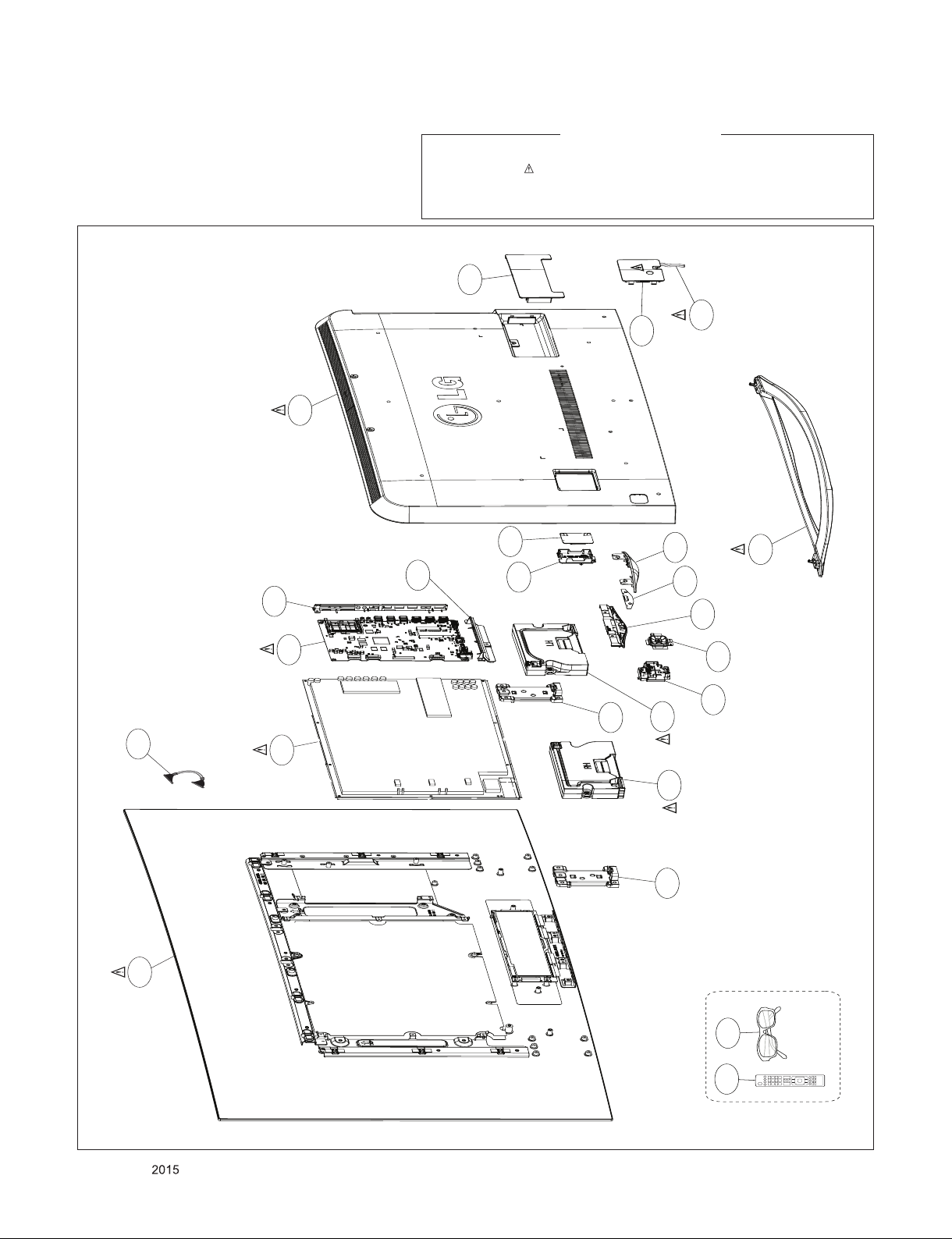
A2
AV1
AG1
700
710
900
200
400
540
521
522
530
501
510
511
500
502
570
571
121
811
810
120
LV1
EXPLODED VIEW
IMPORTANT SAFETY NOTICE
Many electrical and mechanical parts in this chassis have special safety-related characteristics. These
parts are identified by in the Schematic Diagram and EXPLODED VIEW.
It is essential that these special safety parts should be replaced with the same components as
recommended in this manual to prevent X-RADIATION, Shock, Fire, or other Hazards.
Do not modify the original design without permission of manufacturer.
Only for training and service purposes
- 30 -
LGE Internal Use OnlyCopyright © LG Electronics. Inc. All rights reserved.
Page 31
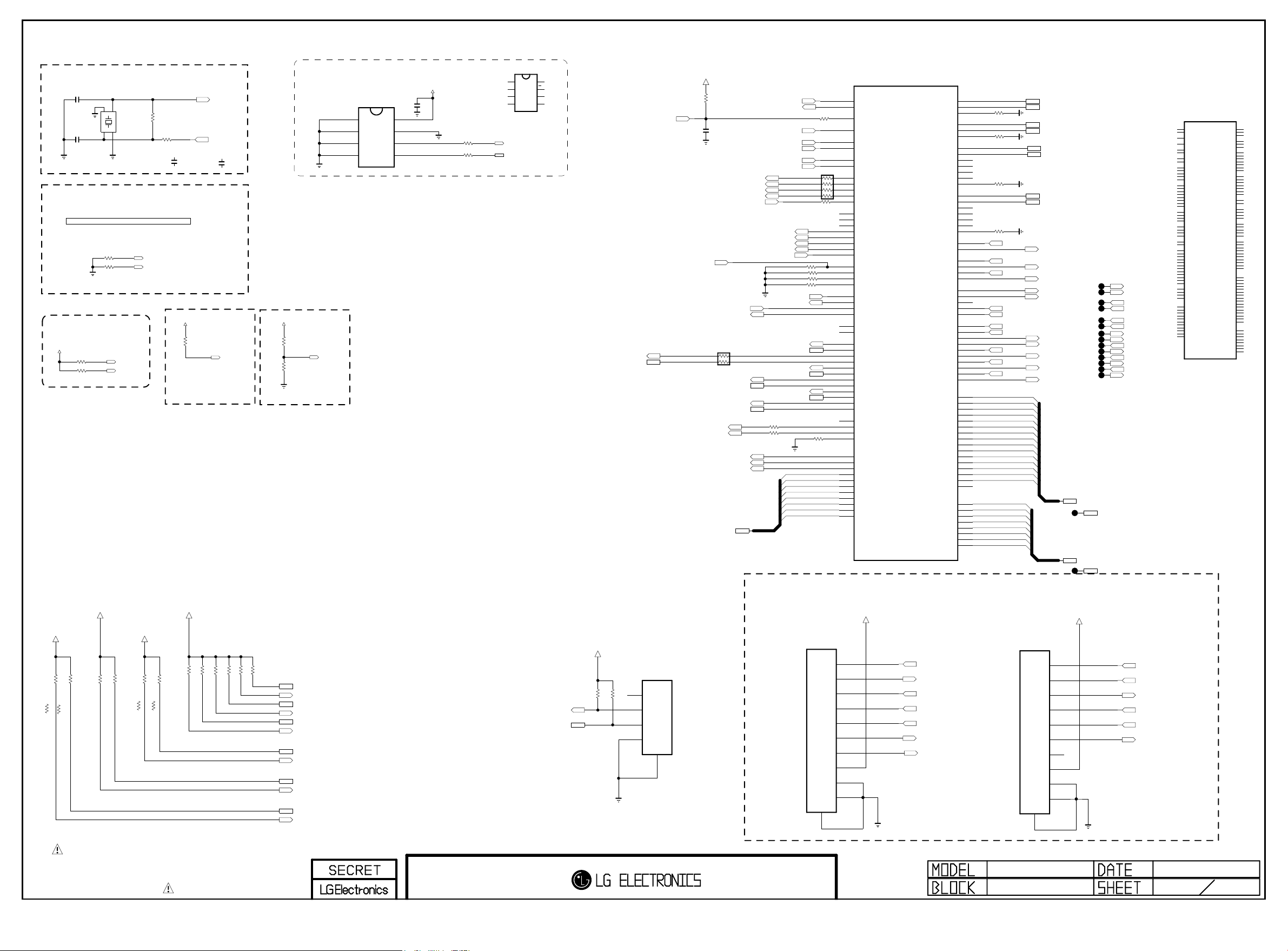
System Configuration
Copyright ⓒ 2015 LG Electronics. Inc. All right reserved.
Only for training and service purposes
LGE Internal Use Only
Clock for M14-A0
MAIN Clock(24Mhz)
LOADCAP_ATSC_PCB
10pF
C101
C102
LOADCAP_ATSC_PCB
System Clock for Analog block(24Mhz)
PLL SET[1:0] : internal pull up
"00" : CPU(1200Mhz),M0 / M1 DDR(792,792 Mhz)
"01" : CPU(1056Mhz),M0 / M1 DDR(672,672 Mhz)
"10" : CPU(1056Mhz),M0 / M1 DDR(792,792 Mhz)
"11" : CPU( 960Mhz),M0 / M1 DDR(792,792 Mhz)
OP MODE[1:0]
"00" : Normal Mode
"01/10/11" : Internal Test mode
+3.3V_NORMAL
R101 3.3K
R102 3.3K
Extenal test only
+3.3V_NORMAL
+3.3V_TUNER
R148
3.3K
R146
3.3K
KR_PIP_NOT
KR_PIP_NOT
1.5K
1.5K
KR_PIP
R146-*1
KR_PIP
R148-*1
10pF
Extenal test only
OPT
OPT
R149
2
3
OPT
R103 3.3K
R104 3.3K
OPT
3.3K
X-TAL_1
GND_1
1
X101
24MHz
4
GND_2
X-TAL_2
PLLSET1
PLLSET0
OPM1
OPM0
+3.3V_TUNER
R150
3.3K
R155
1.2K
KR_PIP_NOT
3.3K
KR_PIP
KR_PIP
R155-*1
1M
R118
R180
560
LOADCAP_DVB_PCB
C101-*1
6.8pF
50V
+3.3V_NORMAL
3.3K
R121
OPT
INSTANT_MODE0
+3.3V_NORMAL
R157
R156
KR_PIP_NOT
3.3K
R156-*1
3.3K
1.2K
XTAL_IN
XTAL_OUT
LOADCAP_DVB_PCB
C102-*1
6.8pF
50V
INSTANT boot MODE
"1 : Instant boot
"0 : normal
(internal pull down)
INSTANT_BOOT
I2C PULL UP
R159
3.3K
R158
3.3K
R160
3.3K
R161
+3.3V_NORMAL
3.3K
R127
OPT
3.3K
R128
BOOT_MODE0
I2C
I2C_1 : AMP
I2C_2 : T-CON,L/DIMING
I2C_3 : MICOM
I2C_4 : S/Demod,T2/Demod, LNB
I2C_5 : NVRAM
I2C_6 : TUNER_MOPLL(T/C,ATV)
R162
3.3K
3.3K
IC103
AT24C256C-SSHL-T
A0
1
A1
2
A2
3
GND
4
NVRAM_ATMEL
BOOT MODE
"0 : EMMC
"1 : TEST MODE
BOOT_MODE
I2C_SDA1
I2C_SCL1
I2C_SDA_MICOM_SOC
I2C_SCL_MICOM_SOC
I2C_SDA2
I2C_SCL2
I2C_SDA4
I2C_SCL4
I2C_SDA5
I2C_SCL5
I2C_SDA6
I2C_SCL6
NVRAM
VCC
8
WP
7
SCL
6
SDA
5
+3.3V_NORMAL
C107
0.1uF
16V
Write Protection
- Low : Normal Operation
- High : Write Protection
R143 33
R144 33
IC103-*1
M24256-BRMN6TP
E0
VCC
1
8
WC
E1
7
2
SCL
E2
6
3
SDA
VSS
5
4
NVRAM_ST
I2C_SCL5
I2C_SDA5
I2C_SCL_MICOM_SOC
I2C_SDA_MICOM_SOC
LOCAL DIMMING I2C CONTROL
+3.3V_NORMAL
OPT
OPT
R105
3.3K
R106
3.3K
LED_SCL
LED_SDA
SOC_RESET
FORCED_JTAG_0
P102
12507WS-04L
1
2
3
4
5
+3.3V_NORMAL
R163
10K
OPT
C104
0.1uF
16V
L/DIM0_VS
L/DIM0_SCLK
L/DIM0_MOSI
IRB_SPI_MOSI/TDO1
IRB_SPI_MISO/TDI1
M_REMOTE_RX
M_REMOTE_TX
1/16W
33
AR100
I2C_SCL4
I2C_SDA4
I2C_SCL6
I2C_SDA6
PWM_DIM2
PWM_DIM
EMMC_CLK
EMMC_CMD
EMMC_RST
EMMC_DATA[0-7]
OPT
XTAL_IN
XTAL_OUT
BOOT_MODE
PLLSET0
PLLSET1
TCK0
TDI0
TRST_N1
IRB_SPI_SS/TMS1
IRB_SPI_CK/TCK1
I2C_SCL1
I2C_SDA1
I2C_SCL2
I2C_SDA2
I2C_SCL5
I2C_SDA5
33
R107
33
R108
OPM0
OPM1
R178 33
OPT
R182 10K
R183 10K
R184 10K
R185 10K
SOC_RX
SOC_TX
EMMC_DATA[7]
EMMC_DATA[6]
EMMC_DATA[5]
EMMC_DATA[4]
EMMC_DATA[3]
EMMC_DATA[2]
EMMC_DATA[1]
EMMC_DATA[0]
12505WS-10A00
JTAG_CPU
B23
A23
R169
AG21
33
AJ18
AB8
AC8
AD8
AE8
AR101
AG30
AG28
AG29
AH29
AJ27
AH27
AG26
AH26
AJ12
AJ13
AH12
AG12
AH23
AG22
AH11
AG11
AG10
AH22
AJ22
AH10
AJ10
AG23
AH24
Y7
Y6
W7
W6
W5
AH7
AJ7
AG8
AH8
AH9
AG9
AJ9
AC6
AC7
AD7
AB7
G32
G33
G31
D31
F33
F32
E32
F31
D33
D32
E31
33
R179
10K
1/16W
5%
Jtag-0 I/F
+3.3V_NORMAL
P103
1
2
3
4
5
6
7
8
9
10
11
M14_LCD
IC101
LG1311
XIN_MAIN
XO_MAIN
PORES_N
BOOT_MODE
PLLSET0
PLLSET1
OPM0
OPM1
L_VSOUT_LD/TRST0_N
DIM0_SCLK/TMS0
DIM1_SCLK/TCK0
DIM1_MOSI/TDI0
DIM0_MOSI/TDO0
SPI_CS0
SPI_SCLK0
SPI_DO0
SPI_DI0/TRST1_N
SPI_CS1/TMS1
SPI_SCLK1/TCK1
SPI_DO1/TDO1
SPI_DI1/TDI1
EXT_INTR0
EXT_INTR1
EXT_INTR2
EXT_INTR3
UART0_RXD
UART0_TXD
UART1_RXD
UART1_TXD
UART1_RTS_N
UART1_CTS_N
SCL0
SDA0
SCL1
SDA1
SCL2
SDA2
SCL3
SDA3
SCL4
SDA4
SCL5
SDA5
PWM0
PWM1
PWM2
PWM_IN
EMMC_CLK
EMMC_CMD
EMMC_RESETN
EMMC_DATA7
EMMC_DATA6
EMMC_DATA5
EMMC_DATA4
EMMC_DATA3
EMMC_DATA2
EMMC_DATA1
EMMC_DATA0
USB2_0_DP0
USB2_0_DM0
USB2_0_TXRTUNE
USB2_1_DP0
USB2_1_DM0
USB2_1_TXRTUNE
USB3_DP0
USB3_DM0
USB3_TXP0
USB3_TXM0
USB3_RXP0
USB3_RXM0
USB3_RESREF0
USB3_DP1
USB3_DM1
USB3_TXP1
USB3_TXM1
USB3_RXP1
USB3_RXM1
USB3_RESREF1
HUB_PORT_OVER0
HUB_VBUS_CTRL0
EB_CS3
EB_CS2
EB_CS1
EB_CS0
EB_WE_N
EB_OE_N
EB_WAIT
EB_BE_N1
EB_BE_N0
CAM_CD1_N
CAM_CD2_N
CAM_CE1_N
CAM_CE2_N
CAM_IREQ_N
CAM_RESET
CAM_INPACK_N
CAM_VCCEN_N
CAM_WAIT_N
CAM_REG_N
EB_ADDR0
EB_ADDR1
EB_ADDR2
EB_ADDR3
EB_ADDR4
EB_ADDR5
EB_ADDR6
EB_ADDR7
EB_ADDR8
EB_ADDR9
EB_ADDR10
EB_ADDR11
EB_ADDR12
EB_ADDR13
EB_ADDR14
EB_ADDR15
EB_DATA0
EB_DATA1
EB_DATA2
EB_DATA3
EB_DATA4
EB_DATA5
EB_DATA6
EB_DATA7
L/DIM0_VS
TDI0
L/DIM0_MOSI
L/DIM0_SCLK
TCK0
SOC_RESET
FORCED_JTAG_0
AN9
AM9
AN8
H32
J31
H33
N31
N32
P33
P32
M32
M33
P31
K33
K32
L32
L31
K31
J32
M31
W28
W29
H28
J30
J28
J29
G30
F30
H29
G29
G28
P28
P27
U28
R29
V27
T28
T29
R28
U27
N29
K30
E30
M30
N28
M28
M29
L29
K29
K28
L28
D30
EB_ADDR[10]
F29
EB_ADDR[11]
C32
EB_ADDR[12]
C33
EB_ADDR[13]
C31
EB_ADDR[14]
B33
B32
A32
B31
A31
A30
B30
C30
C29
(TRST0_N)
(TDO0)
(TMS0)
R1712001%
R1722001%
R1732001%
R1742001%
/USB_OCD1
/USB_OCD2
/USB_OCD3
EB_BE_N1
EB_BE_N0
CAM_CD1_N
CAM_CD2_N
CAM_IREQ_N
CAM_INPACK_N
CAM_WAIT_N
EB_ADDR[0]
EB_ADDR[1]
EB_ADDR[2]
EB_ADDR[3]
EB_ADDR[4]
EB_ADDR[5]
EB_ADDR[6]
EB_ADDR[7]
EB_ADDR[8]
EB_ADDR[9]
EB_DATA[0]
EB_DATA[1]
EB_DATA[2]
EB_DATA[3]
EB_DATA[4]
EB_DATA[5]
EB_DATA[6]
EB_DATA[7]
12505WS-10A00
WIFI_DP
WIFI_DM
USB_DP3
USB_DM3
USB_DP1
USB_DM1
USB_DP2
USB_DM2
USB_CTL1
USB_CTL2
USB_CTL3
EB_WE_N
EB_OE_N
/PCM_CE1
/PCM_CE2
PCM_RESET
PCM_5V_CTL
CAM_REG_N
Jtag-1 I/F
+3.3V_NORMAL
P104
OPT
1
2
3
4
5
6
7
8
9
10
11
EB_ADDR[0-14]
TP102
EB_DATA[0-7]
TP103
PAGE 1
TP104
TP105
TP106
TP107
TP108
TP109
TP110
TP111
TP112
TP113
TP114
TP115
TP116
TP117
EB_WE_N
EB_OE_N
EB_BE_N1
EB_BE_N0
CAM_CD1_N
CAM_CD2_N
/PCM_CE1
/PCM_CE2
CAM_IREQ_N
PCM_RESET
CAM_INPACK_N
PCM_5V_CTL
CAM_WAIT_N
CAM_REG_N
EB_ADDR[0-14]
EB_DATA[0-7]
TRST_N1
IRB_SPI_MISO/TDI1
IRB_SPI_MOSI/TDO1
IRB_SPI_SS/TMS1
IRB_SPI_CK/TCK1
SOC_RESET
M14_OLED_VBY1
LG1311V-B1
IC101-*1
B23
XIN_MAIN
A23
XO_MAIN
AG21
PORES_N
AJ18
BOOT_MODE
AB8
PLLSET0
AC8
PLLSET1
AD8
OPM0
AE8
OPM1
Y7
L_VSOUT_LD/TRST0_N
Y6
DIM0_SCLK/TMS0
W7
DIM1_SCLK/TCK0
W6
DIM1_MOSI/TDI0
W5
DIM0_MOSI/TDO0
AG30
SPI_CS0
AG28
SPI_SCLK0
AG29
SPI_DO0
AH29
SPI_DI0/TRST1_N
AJ27
SPI_CS1/TMS1
AH27
SPI_SCLK1/TCK1
AG26
SPI_DO1/TDO1
AH26
SPI_DI1/TDI1
AJ12
EXT_INTR0
AJ13
EXT_INTR1
AH12
EXT_INTR2
AG12
EXT_INTR3
AH23
UART0_RXD
AG22
UART0_TXD
AH7
UART1_RXD
AJ7
UART1_TXD
AG8
UART1_RTS_N
AH8
UART1_CTS_N
AH11
SCL0
AG11
SDA0
AH9
SCL1
AG9
SDA1
AG10
SCL2
AJ9
SDA2
AH22
SCL3
AJ22
SDA3
AH10
SCL4
AJ10
SDA4
AG23
SCL5
AH24
SDA5
AC6
PWM0
AC7
PWM1
AD7
PWM2
AB7
PWM_IN
G32
EMMC_CLK
G33
EMMC_CMD
G31
EMMC_RESETN
D31
EMMC_DATA7
F33
EMMC_DATA6
F32
EMMC_DATA5
E32
EMMC_DATA4
F31
EMMC_DATA3
D33
EMMC_DATA2
D32
EMMC_DATA1
E31
EMMC_DATA0
USB2_0_DP0
USB2_0_DM0
USB2_0_TXRTUNE
USB2_1_DP0
USB2_1_DM0
USB2_1_TXRTUNE
USB3_DP0
USB3_DM0
USB3_TXP0
USB3_TXM0
USB3_RXP0
USB3_RXM0
USB3_RESREF0
USB3_DP1
USB3_DM1
USB3_TXP1
USB3_TXM1
USB3_RXP1
USB3_RXM1
USB3_RESREF1
HUB_PORT_OVER0
HUB_VBUS_CTRL0
EB_WE_N
EB_OE_N
EB_WAIT
EB_BE_N1
EB_BE_N0
CAM_CD1_N
CAM_CD2_N
CAM_CE1_N
CAM_CE2_N
CAM_IREQ_N
CAM_RESET
CAM_INPACK_N
CAM_VCCEN_N
CAM_WAIT_N
CAM_REG_N
EB_ADDR0
EB_ADDR1
EB_ADDR2
EB_ADDR3
EB_ADDR4
EB_ADDR5
EB_ADDR6
EB_ADDR7
EB_ADDR8
EB_ADDR9
EB_ADDR10
EB_ADDR11
EB_ADDR12
EB_ADDR13
EB_ADDR14
EB_ADDR15
EB_DATA0
EB_DATA1
EB_DATA2
EB_DATA3
EB_DATA4
EB_DATA5
EB_DATA6
EB_DATA7
AN9
AM9
AN8
H32
J31
H33
N31
N32
P33
P32
M32
M33
P31
K33
K32
L32
L31
K31
J32
M31
W28
W29
H28
EB_CS3
J30
EB_CS2
J28
EB_CS1
J29
EB_CS0
G30
F30
H29
G29
G28
P28
P27
U28
R29
V27
T28
T29
R28
U27
N29
K30
E30
M30
N28
M28
M29
L29
K29
K28
L28
D30
F29
C32
C33
C31
B33
B32
A32
B31
A31
A30
B30
C30
C29
THE SYMBOL MARK OF THIS SCHEMETIC DIAGRAM INCORPORATES
SPECIAL FEATURES IMPORTANT FOR PROTECTION FROM X-RADIATION.
FIRE AND ELECTRICAL SHOCK HAZARDS, WHEN SERVICING IF IS
ESSENTIAL THAT ONLY MANUFACTURES SPECIFIED PARTS BE USED FOR
THE CRITICAL COMPONENTS IN THE SYMBOL MARK OF THE SCHEMETIC.
M14-Peripheral
MID_LG1311
M14 Symbol A
2013.04.04
1
31
Page 32
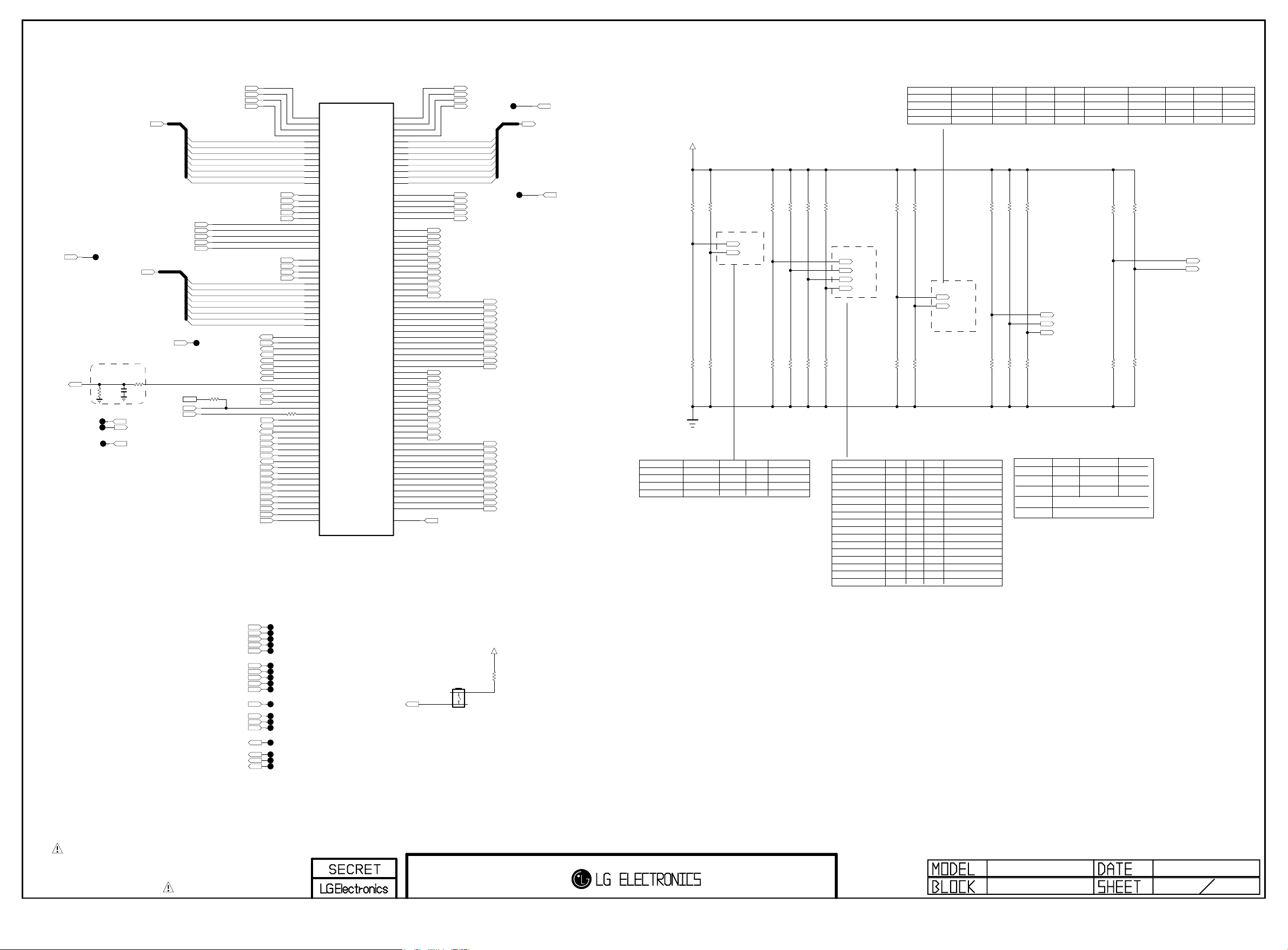
PAGE 2
Copyright ⓒ 2015 LG Electronics. Inc. All right reserved.
Only for training and service purposes
LGE Internal Use Only
FE_DEMOD1_TS_DATA[0-7]
TPI_ERR
AMP_RESET_N
TP226
TP227
FE_DEMOD3_TS_SYNC
FE_DEMOD3_TS_DATA
TPI_DATA[0-7]
Near AMP
C200
1000pF
50V
R231
4.7K
TP228
FE_DEMOD1_TS_CLK
FE_DEMOD1_TS_SYNC
FE_DEMOD1_TS_VAL
FE_DEMOD1_TS_ERROR
FE_DEMOD3_TS_CLK
FE_DEMOD3_TS_VAL
SC_DET
R226
100
1/16W
5%
LED_SDA
INSTANT_BOOT
LED_SCL
CAM_SLIDE_DET
CAM_TRIGGER_DET
/RST_HUB
IC101
LG1311
AH30
TP_DVB_CLK
AH32
TP_DVB_SOP
AH31
TP_DVB_VAL
AH33
TP_DVB_ERR
FE_DEMOD1_TS_DATA[7]
FE_DEMOD1_TS_DATA[6]
FE_DEMOD1_TS_DATA[5]
FE_DEMOD1_TS_DATA[4]
FE_DEMOD1_TS_DATA[3]
FE_DEMOD1_TS_DATA[2]
FE_DEMOD1_TS_DATA[1]
FE_DEMOD1_TS_DATA[0]
FE_DEMOD2_TS_CLK
FE_DEMOD2_TS_SYNC
FE_DEMOD2_TS_VAL
FE_DEMOD2_TS_ERROR
FE_DEMOD2_TS_DATA
TPI_CLK
TPI_SOP
TPI_VAL
SC_DET
/RST_PHY
2D/3D_CTL
BT_RESET
HP_DET
OPT
OPC_EN
DEBUG
BIT0
/RST_HUB
COMP1_DET
BIT1
BIT2
BIT3
BIT4
BIT5
BIT6
BIT7
TPI_ERR
TPI_DATA[0]
TPI_DATA[1]
TPI_DATA[2]
TPI_DATA[3]
TPI_DATA[4]
TPI_DATA[5]
TPI_DATA[6]
TPI_DATA[7]
MODEL_OPT_11
TP225
RF_SWITCH_CTL
/TU_RESET1
/TU_RESET2
R224
33
CAM_SLIDE_DET
CAM_TRIGGER_DET
MODEL_OPT_12
AV1_CVBS_DET
IR_B_RESET
MODEL_OPT_8
MODEL_OPT_9
MODEL_OPT_10 EPI_LOCK8/6
AM33
TP_DVB_DATA7
AL32
TP_DVB_DATA6
AL33
TP_DVB_DATA5
AK32
TP_DVB_DATA4
AK33
TP_DVB_DATA3
AK31
TP_DVB_DATA2
AJ30
TP_DVB_DATA1
AJ31
TP_DVB_DATA0
AL31
STPI0_CLK
AN32
STPI0_SOP
AM32
STPI0_VAL
AN31
STPI0_ERR
AM31
STPI0_DATA
AH28
STPI1_CLK
AJ28
STPI1_SOP
AK30
STPI1_VAL
AJ29
STPI1_ERR
AG27
STPI1_DATA
A28
TPI_CLK
B28
TPI_SOP
B29
TPI_VAL
C28
TPI_ERR
A27
TPI_DATA0
B27
TPI_DATA1
C27
TPI_DATA2
B26
TPI_DATA3
C26
TPI_DATA4
B25
TPI_DATA5
A25
TPI_DATA6
C25
TPI_DATA7
AG13
GPIO31
AJ19
GPIO30
AG14
GPIO29
AG15
GPIO28
AJ15
GPIO27
AH19
GPIO26
AH18
GPIO25
AG19
GPIO24
AH5
GPIO23
AJ5
GPIO22
AJ6
GPIO21
AH6
GPIO20
AG6
AG24
AH16
AJ21
AH21
AG16
AJ24
AH17
AG17
AH13
AH15
AG18
AH14
AJ16
AH20
GPIO19
AG5
GPIO18
AF7
GPIO17
AG7
GPIO16
GPIO15
GPIO14
V29
GPIO13
GPIO12
GPIO11
V28
GPIO10
GPIO9
GPIO8
GPIO7
GPIO6
GPIO5
GPIO4
GPIO3
GPIO2
GPIO1
GPIO0
R225
OPT
33
TPIO_CLK
TPIO_SOP
TPIO_VAL
TPIO_ERR
TPIO_DATA0
TPIO_DATA1
TPIO_DATA2
TPIO_DATA3
TPIO_DATA4
TPIO_DATA5
TPIO_DATA6
TPIO_DATA7
EPI_SOE
EPI_MCLK
EPI_GCLK
EPI_EO
EPI_VST
TX_0N
TX_0P
TX_1N
TX_1P
TX_2N
TX_2P
TX_3N
TX_3P
TX_4N
TX_4P
TX_5N
TX_5P
TX_6N
TX_6P
TX_7N
TX_7P
TX_8N
TX_8P
TX_9N
TX_9P
TX_10N
TX_10P
TX_11N
TX_11P
TX_12N
TX_12P
TX_13N
TX_13P
TX_14N
TX_14P
TX_15N
TX_15P
TX_16N
TX_16P
TX_17N
TX_17P
TX_18N
TX_18P
TX_19N
TX_19P
TX_20N
TX_20P
TX_21N
TX_21P
TX_22N
TX_22P
TX_23N
TX_23P
TX_LOCKN
D28
E29
E28
F28
D27
E27
F27
E26
F26
E25
D25
F25
AA5
AB5
AA7
AA6
AB6
AK8
AL8
AK7
AL7
AM6
AN6
AK6
AL6
AK5
AL5
AN4
AN3
AM2
AM1
AM4
AM3
AL4
AL3
AK2
AK1
AK4
AK3
AJ4
AJ3
AH2
AH1
AH4
AH3
AG4
AG3
AF2
AF1
AF4
AF3
AE4
AE3
AD2
AD1
AD4
AD3
AC4
AC3
AB2
AB1
AB4
AB3
AA4
AA3
AM8
TPO_CLK
TPO_SOP
TPO_VAL
TPO_ERR
TPO_DATA[0]
TPO_DATA[1]
TPO_DATA[2]
TPO_DATA[3]
TPO_DATA[4]
TPO_DATA[5]
TPO_DATA[6]
TPO_DATA[7]
EPI_SOE
MCLK_SOC
GCLK_SOC
EO_SOC
GST_SOC
TXB4N/TX0N
TXB4P/TX0P
TXB3N/TX1NFE_DEMOD3_TS_ERROR
TXB3P/TX1P
TXBCLKN/TX2N
TXBCLKP/TX2P
TXB2N/TX3N
TXB2P/TX3P
TXB1N/TX4N
TXB1P/TX4P
TXB0N/TX5N
TXB0P/TX5P
TXD4N/TX12N
TXD4P/TX12P
TXD3N/TX13N
TXD3P/TX13P
TXDCLKN/TX14N
TXDCLKP/TX14P
TXD2N/TX15N
TXD2P/TX15P
TXD1N/TX16N
TXD1P/TX16P
TXD0N/TX17N
TXD0P/TX17P
TPO_DATA[0-7]
TXA4N/TX6N
TXA4P/TX6P
TXA3N/TX7N
TXA3P/TX7P
TXACLKN/TX8N
TXACLKP/TX8P
TXA2N/TX9N
TXA2P/TX9P
TXA1N/TX10N
TXA1P/TX10P
TXA0N/TX11N
TXA0P/TX11P
TXC4N/TX18N
TXC4P/TX18P
TXC3N/TX19N
TXC3P/TX19P
TXCCLKN/TX20N
TXCCLKP/TX20P
TXC2N/TX21N
TXC2P/TX21P
TXC1N/TX22N
TXC1P/TX22P
TXC0N/TX23N
TXC0P/TX23P
TPO_ERR
EPI_SOE
+3.3V_NORMAL
BIT0_1
R201 10K
BIT0_0
R202 10K
BIT [0/1]
0 / 0
0 / 1
1 / 0
1 / 1
TAIWAN/COLOM
CHINA/HONGKONG
ASIA/AFRICA
EU/CIS
BIT1_1
R203 10K
BIT1_0
R204 10K
ATSC
N/AMERICA
KOREA
S/AMERCIA
Model Option
BIT3_1
BIT2_1
R205 10K
R207 10K
BIT0
BIT1
BIT3_0
BIT2_0
R206 10K
R208 10K
JP
JAPAN
BIT4_1
R209 10K
BIT4_0
R210 10K
BIT5_1
R211 10K
BIT5_0
R212 10K
BIT2
BIT3
BIT4
BIT5
BACK-END OPTIONAREA OPTION
BIT[2/3/4/5]DVB
0 / 0 / 0 / 0
0 / 0 / 0 / 1
0 / 0 / 1 / 0
0 / 0 / 1 / 1
0 / 1 / 0 / 0
0 / 1 / 0 / 1
0 / 1 / 1 / 0
0 / 1 / 1 / 1
1 / 0 / 0 / 0
1 / 0 / 0 / 1
1 / 0 / 1 / 0
1 / 0 / 1 / 1
1 / 1 / 0 / 0
1 / 1 / 0 / 1
1 / 1 / 1 / 0
1 / 1 / 1 / 1
BIT6_1
R213 10K
BIT [6/7]
BIT7_1
R215 10K
0 / 0
0 / 1
1 / 0
1 / 1
EU/CIS
T/C
T2/C/S2/ATV_EXT
T2/C
T2/C/S2/ATV_SOC
BIT6
BIT7
BIT6_0
BIT7_0
R214 10K
R216 10K
TYPE
EPI FHD, 120Hz, V14 (8 lane)
EPI FHD, 120Hz, v14_32inch (6 lane)
EPI FHD, 120Hz, V13 (6 lane)
EPI FHD, 120Hz, V12 (6 lane)
EPI FHD, 60Hz, V14_32 inch (6lane)
LVDS FHD, 120Hz
LVDS FHD, 60Hz
LVDS HD, 60Hz
LVDS FHD, 60Hz, CP BOX
LVDS HD, 60Hz SMALL SMART
Vby1 FHD, 120Hz
LVDS FHD, 120Hz OLED
FRC
FHD
PANEL TYPE
OLED
AJJA
T/C
T2/C/ATV_EXT
T2/C/ATV_SOC
T2/C/S2
DDR3_DDP
R219 10K
R217 10K
DDR3_1.5GB
DDR3_2GB
R220 10K
R218 10K
DDR3_NON_DDP
TAIWAN/COL
T/C
T2/C PIP
T2/C
DDR_3G
R221 10K
R222 10K
NON_DDR_3G
MODEL_OPT_8
MODEL_OPT_9
MODEL_OPT_10
MODEL_OPT_11
MODEL_OPT_12
BRAZILKOREA
ISDB PIP
ISDB
ATV_SOC
ATV_EXT
OPT
R227 10K
NORTH AMERICA
ATSC PIP
ATV_SOC
ATV_EXT
OPT
R229 10K
CHINA/HONG
Default Default
ATSC PIP
MODEL_OPT_8
MODEL_OPT_9
MODEL_OPT_10
OPT
OPT
R230 10K
R228 10K
LOW
DDR3
NON_DDP
DDR3
FOR UD
NON_DDR3 3G
NOT GPIO! OLED ECO POWER CTL
HIGH
DDP
1.5GB
2GB
DDR3 3G
JAPAN
MODEL_OPT_11
MODEL_OPT_12
FE_DEMOD2_TS_CLK
FE_DEMOD2_TS_SYNC
FE_DEMOD2_TS_VAL
FE_DEMOD2_TS_ERROR
FE_DEMOD2_TS_DATA
FE_DEMOD3_TS_CLK
FE_DEMOD3_TS_SYNC
FE_DEMOD3_TS_VAL
FE_DEMOD3_TS_ERROR
FE_DEMOD3_TS_DATA
TPI_DATA[0-7]
TPO_DATA[0-7]
THE SYMBOL MARK OF THIS SCHEMETIC DIAGRAM INCORPORATES
SPECIAL FEATURES IMPORTANT FOR PROTECTION FROM X-RADIATION.
FIRE AND ELECTRICAL SHOCK HAZARDS, WHEN SERVICING IF IS
ESSENTIAL THAT ONLY MANUFACTURES SPECIFIED PARTS BE USED FOR
M14-Display In/Out
THE CRITICAL COMPONENTS IN THE SYMBOL MARK OF THE SCHEMETIC.
TPI_CLK
TPI_SOP
TPI_VAL
TPO_CLK
TPO_SOP
TPO_VAL
TP202
TP203
TP204
TP205
TP206
TP207
TP208
TP209
TP210
TP211
TP212
TP213
TP214
TP215
TP221
TP218
TP219
TP220
DEBUG
+3.3V_NORMAL
SW201
JTP-1127WEM
12
3
4
For ISP
R223
3.3K
MID_LG1311
M14 Symbol B
2013.04.04
2
31
Page 33
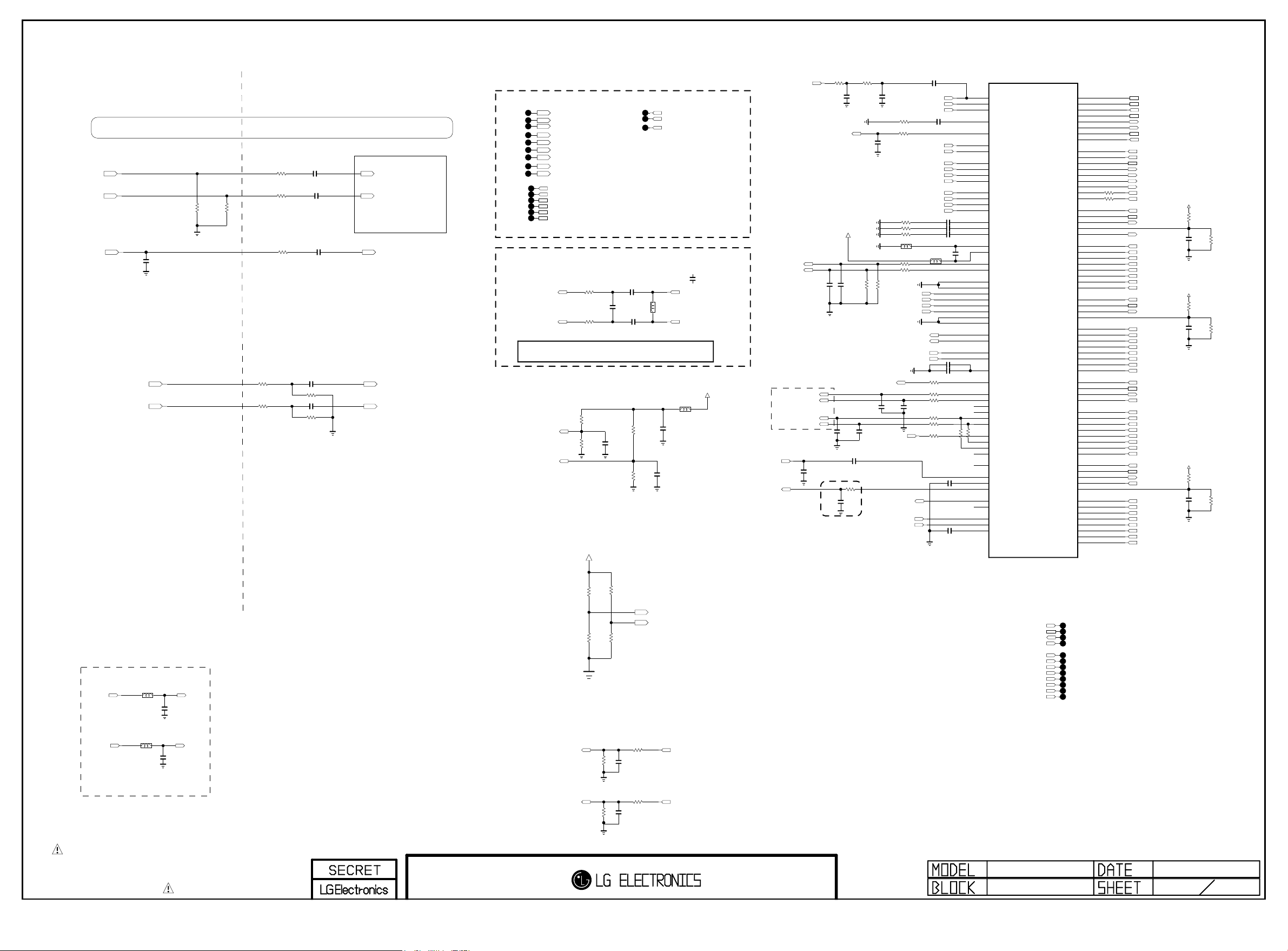
PLACE AT JACK SIDE
Copyright ⓒ 2015 LG Electronics. Inc. All right reserved.
Only for training and service purposes
LGE Internal Use Only
Place JACK Side
AV1_CVBS/COMP1_Y Circuit was moved to 34Page
COMP1_Pb
COMP1_Pr
TU_CVBS
COMP1/AV1/DVI_L_IN
COMP1/AV1/DVI_R_IN
C303
150pF
50V
OPT
1005
75
1%
R318
1005
1%
75
R326
Place SOC Side
33
R333
R335 33
TU_ALL_2178B
R329 100
AUDIO IN
R309 27K
R310 27K
C316 4.7uF
1%
C317 4.7uF
1%
R323 10K
C322 0.047uF
C324 0.047uF
TU_ALL_2178B
C318 0.047uF
R322 10K
1%
1%
COMP2_PB_IN_SOC
COMP2_PR_IN_SOC
TU_CVBS_SOC
AUAD_L_CH3_IN
AUAD_R_CH3_IN
COMP
TP308
TP310
TP311
TP312
TP313
TP314
TP315
TP316
TP317
TP302
TP303
TP304
TP305
TP306
TP307
SC_CVBS_IN_SOC
SC_FB_SOC
SC_ID_SOC
COMP1_PB_IN_SOC
COMP1_Y_IN_SOC
COMP1_Y_IN_SOC_SOY
COMP1_PR_IN_SOC
AUAD_L_CH2_IN
AUAD_R_CH2_IN
SMARTCARD_DATA/SD_EMMC_CLK
SMARTCARD_VCC/SD_EMMC_CMD
SMARTCARD_DET/SD_EMMC_DATA[3]
SMARTCARD_RST/SD_EMMC_DATA[2]
SMARTCARD_PWR_SEL/SD_EMMC_DATA[1]
SMARTCARD_CLK/SD_EMMC_DATA[0]
TP318
TP319
TP320
Placed as close as possible to LG1311
Tuner IF Filter
C331
22pF
TU_ALL_IntDemod
C332
0.01uF
C333
0.01uF
TU_ALL_IntDemod
TU_ALL_IntDemod
ADC_I_INN
To ADC
ADC_I_INP
C331 option
- TU_IntDemod_IF_22p -> EU/AJ All_IndDemod, US/KR/BR/TW/CO 2tuner All
- TU_IntDemod_IF_15p -> US/KR/BR/TW/CO 1tuner All
R344
R345
TU_ALL_IntDemod
51
TU_IntDemod_IF_22p
51
Placed as close as possible to IC101
R37 4
51K
AUAD_L_REF
1%
R37 8
47K
1%
C313
4.7uF
10V
R38 0
51K
1%
AUAD_R_REF
R38 1
47K
1%
DDR3 VENDOR OPTION
+3.3V_NORMAL
SCART_LOUT_SOC
SCART_ROUT_SOC
DTV/MNT_V_OUT_SOC
TU_IntDemod_IF_15p
C331-*1
15pF
50V
IF_N
L303
OPT
IF_P
AVDD25
L307
120-ohm
C354
10uF
10V
C353
4.7uF
10V
SOC_CVBS_OUT
SCART_LOUT_SOC
SCART_ROUT_SOC
TUNER_SIF
IF_AGC
AUD_MASTER_CLK
AUD_LRCH
AUD_SCK
AUD_LRCK
MAIN I2S_I/F
OPT
INT_ADEMOD
R11022
390
INT_ADEMOD
DTV/MNT_V_OUT_SOC
AVDD25
EU
C334
0.01uF
50V
C335
22pF
OPT
TU_ALL_2178B
C312 0.1uF
C309
1000pF
50V
C338
0.1uF
OPT
Close to IC101
INT_ADEMOD
R11023
390
INT_ADEMOD
C11009
68pF
50V
OPT
EU
C336
0.01uF
EU
50V
R351 22K
SPDIF_OUT
C337
33pF
OPT
TU_ALL_IntDemod
R350
470
SOC_CVBS_OUT
C11010
68pF
50V
R356
R353 0
C339
100pF
50V
COMP1_Y_IN_SOC_SOY
COMP2_Y_IN_SOC_SOY
R357 68
R358 68
R359 68
BLM15BD121SN1
R354 0
R355 0
EU
AUAD_L_CH2_IN
AUAD_R_CH2_IN
R352 22K
AUAD_L_CH3_IN
AUAD_R_CH3_IN
C340
22pF
OPT
I2S_AMP
ADC_I_INP
ADC_I_INN
C11011
TU_CVBS_SOC
SC_CVBS_IN_SOC
AV1_CVBS_IN_SOC
C343 0.047uF
68
EU
SC_ID_SOC
SC_FB_SOC
COMP1_Y_IN_SOC
COMP1_PB_IN_SOC
COMP1_PR_IN_SOC
COMP2_Y_IN_SOC
COMP2_PB_IN_SOC
COMP2_PR_IN_SOC
L304
BLM15BD121SN1
EU
EU
AUDA_OUTL
AUDA_OUTR
AUAD_R_REF
AUAD_L_REF
R360 33
R365 100
R366 100
C342
22pF
OPT
R368 100
R369
GOOGLE
R367 0
INT_ADEMOD
0.1uF
16V
0.047uF
C344
C345 0.047uF
C346 0.047uF
C349
0.1uF
L305
16V
10uF 10VC347
C348 2.2uF
10V
100
GOOGLE
R371 0
C351 0.1uF
C352 0.1uF
GOOGLE
R370 0
AL27
AK26
AM27
AL26
AN27
AL25
AM25
AN23
AL22
AK21
AK22
AL24
AK23
AL23
AK24
AL21
AM23
AN25
AM21
AN21
AK16
AL16
AL19
AK19
AN19
AM19
AN17
AM17
AL17
AK17
AK20
AL20
AK18
AL18
AN15
AM15
AN11
AK11
AK10
AL10
AL11
AM11
AK29
AL29
AM29
AK27
AL30
AK28
AL28
AN29
AD5
AE5
AE7
AE6
AD6
IC101
LG1311
CVBS_IN1
CVBS_IN2
CVBS_IN3
CVBS_VCM
BUF_OUT1
SC1_SID
SC1_FB
SOY1_IN
Y1_IN
PB1_IN
PR1_IN
SOY2_IN
Y2_IN
PB2_IN
PR2_IN
ADC1_COM
ADC2_COM
ADC3_COM
AVSS25_COMP_REF
AVDD25_COMP_REF
AUDA_SCART_OUTL
AUDA_SCART_OUTR
AUAD_L_CH1_IN
AUAD_R_CH1_IN
AUAD_L_CH2_IN
AUAD_R_CH2_IN
AUAD_L_CH3_IN
AUAD_R_CH3_IN
AUAD_L_CH4_IN
AUAD_R_CH4_IN
AUDA_OUTL
AUDA_OUTR
AUAD_L_REF
AUAD_R_REF
AUD_VBG_EXT
IEC958OUT
AUDCLK_OUT
DAC_LRCH
DAC_SLRCH
DAC_CLFCH
DAC_SCK
DAC_LRCK
PCMI3LRCH
PCMI3LRCK
PCMI3SCK
AUDCLK_IN
FRC_LRSYNC
AAD_ADC_SIF
AAD_ADC_SIFM
IFAGC
DMD_DAC_OUT
DMD_SIF_OUT
DMD_ADC_INP
DMD_ADC_INN
DMD_ADC_INCOM
SD_CLK
SD_CMD
SD_CD_N
SD_WP_N
SD_DATA3
SD_DATA2
SD_DATA1
SD_DATA0
RMII_REF_CLK
RMII_CRS_DV
RMII_MDIO
RMII_MDC
RMII_TXEN
RMII_TXD1
RMII_TXD0
RMII_RXD1
RMII_RXD0
HDMI_1_SCL
HDMI_1_SDA
HDMI_1_HPD
HDMI_1_5V_DET
HDMI_1_ARC
HDMI_1_RX_0
HDMI_1_RX_0B
HDMI_1_RX_1
HDMI_1_RX_1B
HDMI_1_RX_2
HDMI_1_RX_2B
HDMI_1_RX_C
HDMI_1_RX_CB
HDMI_2_SCL
HDMI_2_SDA
HDMI_2_HPD
HDMI_2_5V_DET
HDMI_2_RX_0
HDMI_2_RX_0B
HDMI_2_RX_1
HDMI_2_RX_1B
HDMI_2_RX_2
HDMI_2_RX_2B
HDMI_2_RX_C
HDMI_2_RX_CB
HDMI_3_SCL
HDMI_3_SDA
HDMI_3_HPD
HDMI_3_5V_DET
HDMI_3_RX_0
HDMI_3_RX_0B
HDMI_3_RX_1
HDMI_3_RX_1B
HDMI_3_RX_2
HDMI_3_RX_2B
HDMI_3_RX_C
HDMI_3_RX_CB
HDMI_4_SCL
HDMI_4_SDA
HDMI_4_CBUS_HPD
HDMI_4_CD_SENSE
HDMI_4_5V_DET
HDMI_4_RX_0
HDMI_4_RX_0B
HDMI_4_RX_1
HDMI_4_RX_1B
HDMI_4_RX_2
HDMI_4_RX_2B
HDMI_4_RX_C
HDMI_4_RX_CB
E22
D22
F22
F24
D24
E24
F23
E23
AK14
AK12
AL12
AK13
AL13
AM13
AN13
AL14
AK15
AE27
AF28
AE29
AF27
AE28
AF33
AF32
AE31
AE30
AD31
AD30
AF31
AF30
AD28
AD29
AC27
AD27
AC31
AC30
AB33
AB32
AA31
AA30
AD32
AD33
AB28
AB27
AB29
AC28
Y32
Y33
W31
W30
V33
V32
Y31
Y30
Y27
AA28
Y28
AA29
AA27
T31
T30
T32
T33
R31
R30
U31
U30
PAGE 3
SMARTCARD_CLK/SD_EMMC_DATA[0]
SMARTCARD_RST/SD_EMMC_DATA[2]
SMARTCARD_VCC/SD_EMMC_CMD
SMARTCARD_PWR_SEL/SD_EMMC_DATA[1]
DDR3_OPT1
DDR3_OPT2
SMARTCARD_DET/SD_EMMC_DATA[3]
SMARTCARD_DATA/SD_EMMC_CLK
EPHY_REFCLK
EPHY_CRS_DV
EPHY_MDIO
EPHY_MDC
EPHY_EN
EPHY_TXD1
EPHY_TXD0
R520733
EPHY_RXD1
R520633
EPHY_RXD0
DDC_SCL_1
DDC_SDA_1
HDMI_HPD_1
SPDIF_OUT_ARC
D0+_HDMI1
D0-_HDMI1
D1+_HDMI1
D1-_HDMI1
D2+_HDMI1
D2-_HDMI1
CK+_HDMI1
CK-_HDMI1
DDC_SCL_2
DDC_SDA_2
HDMI_HPD_2
D0+_HDMI2
D0-_HDMI2
D1+_HDMI2
D1-_HDMI2
D2+_HDMI2
D2-_HDMI2
CK+_HDMI2
CK-_HDMI2
DDC_SCL_3
DDC_SDA_3
HDMI_HPD_3
5V_HDMI_3_SOC
D0+_HDMI3
D0-_HDMI3
D1+_HDMI3
D1-_HDMI3
D2+_HDMI3
D2-_HDMI3
CK+_HDMI3
CK-_HDMI3
DDC_SCL_4
DDC_SDA_4
HDMI_HPD_4
MHL_DET
D0+_HDMI4
D0-_HDMI4
D1+_HDMI4
D1-_HDMI4
D2+_HDMI4
D2-_HDMI4
CK+_HDMI4
CK-_HDMI4
5V_HDMI_1
R372
10
C356
1uF
10V
5V_HDMI_2
R373
10
C357
1uF
10V
5V_HDMI_4
R375
10
C359
1uF
10V
R376
5.1K
R377
5.1K
R379
5.1K
HP_OUT
L308
BLM18PG121SN1D
HP_LOUT_AMP
BLM18PG121SN1D
HP_ROUT_AMP
HP_OUT
L309
HP_OUT
C365
0.22uF
10V
HP_OUT
C366
0.22uF
10V
HP_LOUT
HP_ROUT
Place at JACK SIDE
THE SYMBOL MARK OF THIS SCHEMETIC DIAGRAM INCORPORATES
SPECIAL FEATURES IMPORTANT FOR PROTECTION FROM X-RADIATION.
FIRE AND ELECTRICAL SHOCK HAZARDS, WHEN SERVICING IF IS
ESSENTIAL THAT ONLY MANUFACTURES SPECIFIED PARTS BE USED FOR
THE CRITICAL COMPONENTS IN THE SYMBOL MARK OF THE SCHEMETIC.
M14-AV In/Out
HP_LOUT_MAIN
HP_ROUT_MAIN
4.7K
4.7K
R384
R382
OPT
OPT
R383 4.7K
R385 4.7K
AUDIO OUT
R303
22K
R304
22K
R311 0
C305
0.01uF
50V
R312 0
C306
0.01uF
50V
DDR3_OPT1
DDR3_OPT2
AUDA_OUTL
AUDA_OUTR
DDC_SCL_3
DDC_SDA_3
HDMI_HPD_3
5V_HDMI_3_SOC
D0+_HDMI3
D0-_HDMI3
D1+_HDMI3
D1-_HDMI3
D2+_HDMI3
D2-_HDMI3
CK+_HDMI3
CK-_HDMI3
MID_LG1311
M14 Symbol C
TP321
TP322
TP323
TP324
TP325
TP326
TP327
TP328
TP329
TP330
TP331
TP332
2013.04.04
3
31
Page 34
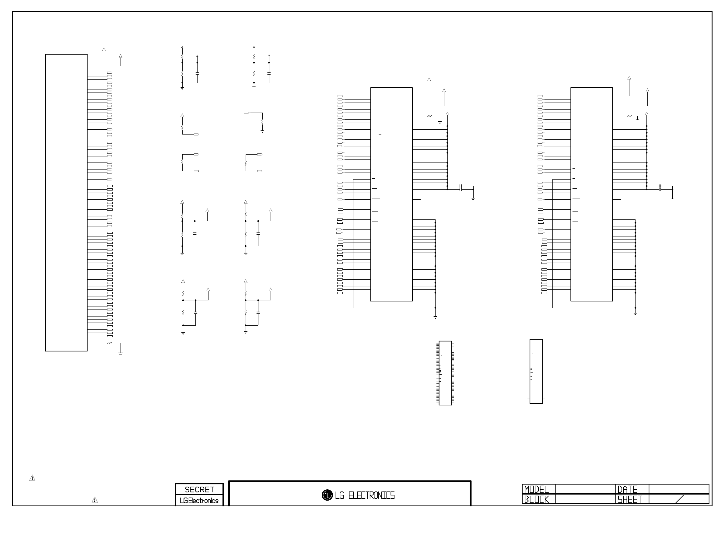
PAGE 4
Copyright ⓒ 2015 LG Electronics. Inc. All right reserved.
Only for training and service purposes
LGE Internal Use Only
IC101
LG1311
M0_DDR_U_CLKP
M0_DDR_U_CLKN
M0_DDR_D_CLKP
M0_DDR_D_CLKN
M0_DDR_RESET_N
M0_DDR_DQS_P0
M0_DDR_DQS_N0
M0_DDR_DQS_P1
M0_DDR_DQS_N1
M0_DDR_DQS_P2
M0_DDR_DQS_N2
M0_DDR_DQS_P3
M0_DDR_DQS_N3
M0_DDR_VREF1
M0_DDR_VREF2
M0_DDR_A0
M0_DDR_A1
M0_DDR_A2
M0_DDR_A3
M0_DDR_A4
M0_DDR_A5
M0_DDR_A6
M0_DDR_A7
M0_DDR_A8
M0_DDR_A9
M0_DDR_A10
M0_DDR_A11
M0_DDR_A12
M0_DDR_A13
M0_DDR_A14
M0_DDR_A15
M0_DDR_BA0
M0_DDR_BA1
M0_DDR_BA2
M0_DDR_CKE
M0_DDR_ODT
M0_DDR_RASN
M0_DDR_CASN
M0_DDR_WEN
M0_DDR_DM0
M0_DDR_DM1
M0_DDR_DM2
M0_DDR_DM3
M0_DDR_DQ0
M0_DDR_DQ1
M0_DDR_DQ2
M0_DDR_DQ3
M0_DDR_DQ4
M0_DDR_DQ5
M0_DDR_DQ6
M0_DDR_DQ7
M0_DDR_DQ8
M0_DDR_DQ9
M0_DDR_DQ10
M0_DDR_DQ11
M0_DDR_DQ12
M0_DDR_DQ13
M0_DDR_DQ14
M0_DDR_DQ15
M0_DDR_DQ16
M0_DDR_DQ17
M0_DDR_DQ18
M0_DDR_DQ19
M0_DDR_DQ20
M0_DDR_DQ21
M0_DDR_DQ22
M0_DDR_DQ23
M0_DDR_DQ24
M0_DDR_DQ25
M0_DDR_DQ26
M0_DDR_DQ27
M0_DDR_DQ28
M0_DDR_DQ29
M0_DDR_DQ30
M0_DDR_DQ31
M0_DDR_ZQCAL
VREF_M0_0
A22
A3
E13
E11
E15
E17
D8
D16
D9
E16
E9
E14
D7
D10
D11
D14
E10
E12
D17
E8
D13
C8
B8
C17
B17
D12
E19
D19
D18
E18
D15
B18
C18
B16
A16
B9
C9
B7
A7
A15
A18
A6
A9
B20
B13
C21
C14
A21
A13
B21
C13
B14
B19
C15
C20
C16
A19
B15
C19
B11
C5
C12
B4
A12
A4
B12
C4
B5
B10
C6
C11
C7
A10
B6
C10
E7
VREF_M0_1
R401 240
M0_DDR_A0
M0_DDR_A1
M0_DDR_A2
M0_DDR_A3
M0_DDR_A4
M0_DDR_A5
M0_DDR_A6
M0_DDR_A7
M0_DDR_A8
M0_DDR_A9
M0_DDR_A10
M0_DDR_A11
M0_DDR_A12
M0_DDR_A13
M0_DDR_A14
M0_DDR_A15
M0_DDR_BA0
M0_DDR_BA1
M0_DDR_BA2
M0_U_CLK
M0_U_CLKN
M0_D_CLK
M0_DDR_CKE
M0_DDR_ODT
M0_DDR_RASN
M0_DDR_CASN
M0_DDR_WEN
M0_DDR_RESET_N
M0_DDR_DQS0
M0_DDR_DQS_N0
M0_DDR_DQS1
M0_DDR_DQS_N1
M0_DDR_DQS2
M0_DDR_DQS_N2
M0_DDR_DQS3
M0_DDR_DQS_N3
M0_DDR_DM0
M0_DDR_DM1
M0_DDR_DM2
M0_DDR_DM3
M0_DDR_DQ0
M0_DDR_DQ1
M0_DDR_DQ2
M0_DDR_DQ3
M0_DDR_DQ4
M0_DDR_DQ5
M0_DDR_DQ6
M0_DDR_DQ7
M0_DDR_DQ8
M0_DDR_DQ9
M0_DDR_DQ10
M0_DDR_DQ11
M0_DDR_DQ12
M0_DDR_DQ13
M0_DDR_DQ14
M0_DDR_DQ15
M0_DDR_DQ16
M0_DDR_DQ17
M0_DDR_DQ18
M0_DDR_DQ19
M0_DDR_DQ20
M0_DDR_DQ21
M0_DDR_DQ22
M0_DDR_DQ23
M0_DDR_DQ24
M0_DDR_DQ25
M0_DDR_DQ26
M0_DDR_DQ27
M0_DDR_DQ28
M0_DDR_DQ29
M0_DDR_DQ30
M0_DDR_DQ31
1%
+1.5V_DDR
R402
R403
+1.5V_DDR
OPT
+1.5V_DDR
R406
R407
+1.5V_DDR
R408
R409
VREF_M0_0
1K 1%
1K 1%
C401
R404
10K
100
R40 5
M0_DDR_VREFCA
1K 1%
C402
0.1uF
1K 1%
M0_DDR_VREFDQ
1K 1%
0.1uF
1K 1%
C403
0.1uF
M0_DDR_CKE
M0_DDR_RESET_N
M0_D_CLK
M0_D_CLKN
+1.5V_DDR
+1.5V_DDR
R411
R412
+1.5V_DDR
R413
R414
VREF_M0_1
R415
1K 1%
R416
1K 1%
R417
10K
M0_U_CLK
100
R41 0
M0_U_CLKN
M0_1_DDR_VREFCA
1K 1%
C406
0.1uF
1K 1%
M0_1_DDR_VREFDQ
1K 1%
0.1uF
1K 1%
C407
C408
0.1uF
M0_DDR_A0
M0_DDR_A1
M0_DDR_A2
M0_DDR_A3
M0_DDR_A4
M0_DDR_A5
M0_DDR_A6
M0_DDR_A7
M0_DDR_A8
M0_DDR_A9
M0_DDR_A10
M0_DDR_A11
M0_DDR_A12
M0_DDR_A13
M0_DDR_A14
M0_DDR_A15
M0_DDR_BA0
M0_DDR_BA1
M0_DDR_BA2
M0_D_CLK
M0_D_CLKN
M0_DDR_CKE
M0_DDR_ODT
M0_DDR_RASN
M0_DDR_CASN
M0_DDR_WEN
M0_DDR_RESET_N
M0_DDR_DQS0
M0_DDR_DQS_N0
M0_DDR_DQS1
M0_DDR_DQS_N1
M0_DDR_DM0
M0_DDR_DM1
M0_DDR_DQ0
M0_DDR_DQ1
M0_DDR_DQ2
M0_DDR_DQ3
M0_DDR_DQ4
M0_DDR_DQ5
M0_DDR_DQ6
M0_DDR_DQ7
M0_DDR_DQ8
M0_DDR_DQ9
M0_DDR_DQ10
M0_DDR_DQ11
M0_DDR_DQ12
M0_DDR_DQ13
M0_DDR_DQ14
M0_DDR_DQ15
IC401
H5TQ4G63AFR-PBC
DDR3
N3
P7
P3
N2
P8
P2
R8
R2
T8
R3
L7
R7
N7
T3
T7
M7
M2
N8
M3
J7
K7
K9
L2
K1
J3
K3
L3
T2
F3
G3
C7
B7
E7
D3
E3
F7
F2
F8
H3
H8
G2
H7
D7
C3
C8
C2
A7
A2
B8
A3
4Gbit
A0
(x16)
A1
DDR_512MB_HYNIX_1600_29n
A2
A3
A4
A5
A6
A7
A8
A9
A10/AP
A11
A12/BC
A13
A14
A15
BA0
BA1
BA2
CK
CK
CKE
CS
ODT
RAS
CAS
WE
RESET
DQSL
DQSL
DQSU
DQSU
DML
DMU
DQL0
DQL1
DQL2
DQL3
DQL4
DQL5
DQL6
DQL7
DQU0
DQU1
DQU2
DQU3
DQU4
DQU5
DQU6
DQU7
VREFCA
VREFDQ
VDD_1
VDD_2
VDD_3
VDD_4
VDD_5
VDD_6
VDD_7
VDD_8
VDD_9
VDDQ_1
VDDQ_2
VDDQ_3
VDDQ_4
VDDQ_5
VDDQ_6
VDDQ_7
VDDQ_8
VDDQ_9
NC_1
NC_2
NC_3
NC_4
VSS_1
VSS_2
VSS_3
VSS_4
VSS_5
VSS_6
VSS_7
VSS_8
VSS_9
VSS_10
VSS_11
VSS_12
VSSQ_1
VSSQ_2
VSSQ_3
VSSQ_4
VSSQ_5
VSSQ_6
VSSQ_7
VSSQ_8
VSSQ_9
ZQ
M0_DDR_VREFCA
M0_DDR_VREFDQ
M8
H1
R418
L8
240
1%
B2
D9
G7
K2
K8
N1
N9
R1
R9
A1
A8
C1
C9
D2
E9
F1
H2
H9
J1
J9
L1
L9
A9
B3
E1
G8
J2
J8
M1
M9
P1
P9
T1
T9
B1
B9
D1
D8
E2
E8
F9
G1
G9
+1.5V_DDR
IC401-*1
MT41K256M16HA-125:E
DDR_512MB_MICRON
N3
A0
VREFCA
P7
A1
P3
A2
N2
A3
VREFDQ
P8
A4
P2
A5
R8
A6
R2
A7
T8
A8
R3
VDD_1
A9
L7
VDD_2
A10/AP
R7
VDD_3
A11
N7
VDD_4
A12/BC
T3
A13
VDD_5
VDD_6
M7
NC_5
VDD_7
VDD_8
M2
BA0
VDD_9
N8
BA1
M3
BA2
VDDQ_1
J7
CK
VDDQ_2
K7
CK
VDDQ_3
K9
CKE
VDDQ_4
VDDQ_5
L2
CS
VDDQ_6
K1
ODT
VDDQ_7
J3
RAS
VDDQ_8
K3
CAS
VDDQ_9
L3
WE
NC_1
T2
RESET
NC_2
NC_3
NC_4
F3
DQSL
G3
DQSL
C7
DQSU
VSS_1
B7
DQSU
VSS_2
VSS_3
E7
DML
VSS_4
D3
DMU
VSS_5
VSS_6
E3
DQ0
VSS_7
F7
DQ1
VSS_8
F2
DQ2
VSS_9
F8
DQ3
VSS_10
H3
DQ4
VSS_11
H8
DQ5
VSS_12
G2
DQ6
H7
DQ7
VSSQ_1
D7
DQ8
VSSQ_2
C3
DQ9
VSSQ_3
C8
DQ10
VSSQ_4
C2
DQ11
VSSQ_5
A7
DQ12
VSSQ_6
A2
DQ13
VSSQ_7
B8
DQ14
VSSQ_8
A3
DQ15
VSSQ_9
C413 1uF
C414 1uF
M8
H1
L8
ZQ
B2
D9
G7
K2
K8
N1
N9
R1
R9
A1
A8
C1
C9
D2
E9
F1
H2
H9
J1
J9
L1
L9
T7
A14
A9
B3
E1
G8
J2
J8
M1
M9
P1
P9
T1
T9
B1
B9
D1
D8
E2
E8
F9
G1
G9
M0_DDR_A0
M0_DDR_A1
M0_DDR_A2
M0_DDR_A3
M0_DDR_A4
M0_DDR_A5
M0_DDR_A6
M0_DDR_A7
M0_DDR_A8
M0_DDR_A9
M0_DDR_A10
M0_DDR_A11
M0_DDR_A12
M0_DDR_A13
M0_DDR_A14
M0_DDR_A15
M0_DDR_BA0M0_D_CLKN
M0_DDR_BA1
M0_DDR_BA2
M0_U_CLK
M0_U_CLKN
M0_DDR_CKE
M0_DDR_ODT
M0_DDR_RASN
M0_DDR_CASN
M0_DDR_WEN
M0_DDR_RESET_N
M0_DDR_DQS2
M0_DDR_DQS_N2
M0_DDR_DQS3
M0_DDR_DQS_N3
M0_DDR_DM2
M0_DDR_DM3
M0_DDR_DQ16
M0_DDR_DQ17
M0_DDR_DQ18
M0_DDR_DQ19
M0_DDR_DQ20
M0_DDR_DQ21
M0_DDR_DQ22
M0_DDR_DQ23
M0_DDR_DQ24
M0_DDR_DQ25
M0_DDR_DQ26
M0_DDR_DQ27
M0_DDR_DQ28
M0_DDR_DQ29
M0_DDR_DQ30
M0_DDR_DQ31
MT41K256M16HA-125:E
N3
A0
P7
A1
P3
A2
N2
A3
P8
A4
P2
A5
R8
A6
R2
A7
T8
A8
R3
A9
L7
A10/AP
R7
A11
N7
A12/BC
T3
A13
M7
NC_5
M2
BA0
N8
BA1
M3
BA2
J7
CK
K7
CK
K9
CKE
L2
CS
K1
ODT
J3
RAS
K3
CAS
L3
WE
T2
RESET
F3
DQSL
G3
DQSL
C7
DQSU
B7
DQSU
E7
DML
D3
DMU
E3
DQ0
F7
DQ1
F2
DQ2
F8
DQ3
H3
DQ4
H8
DQ5
G2
DQ6
H7
DQ7
D7
DQ8
C3
DQ9
C8
DQ10
C2
DQ11
A7
DQ12
A2
DQ13
B8
DQ14
A3
DQ15
IC402-*1
DDR_512MB_MICRON
IC402
H5TQ4G63AFR-PBC
DDR3
N3
4Gbit
A0
P7
(x16)
A1
P3
DDR_512MB_HYNIX_1600_29n
A2
N2
A3
P8
A4
P2
A5
R8
A6
R2
A7
T8
A8
R3
A9
L7
A10/AP
R7
A11
N7
A12/BC
T3
A13
T7
A14
M7
A15
M2
BA0
N8
BA1
M3
BA2
J7
CK
K7
CK
K9
CKE
L2
CS
K1
ODT
J3
RAS
K3
CAS
L3
WE
T2
RESET
F3
DQSL
G3
DQSL
C7
DQSU
B7
DQSU
E7
DML
D3
DMU
E3
DQL0
F7
DQL1
F2
DQL2
F8
DQL3
H3
DQL4
H8
DQL5
G2
DQL6
H7
DQL7
D7
DQU0
C3
DQU1
C8
DQU2
C2
DQU3
A7
DQU4
A2
DQU5
B8
DQU6
A3
DQU7
M8
VREFCA
H1
VREFDQ
L8
ZQ
B2
VDD_1
D9
VDD_2
G7
VDD_3
K2
VDD_4
K8
VDD_5
N1
VDD_6
N9
VDD_7
R1
VDD_8
R9
VDD_9
A1
VDDQ_1
A8
VDDQ_2
C1
VDDQ_3
C9
VDDQ_4
D2
VDDQ_5
E9
VDDQ_6
F1
VDDQ_7
H2
VDDQ_8
H9
VDDQ_9
J1
NC_1
J9
NC_2
L1
NC_3
L9
NC_4
T7
A14
A9
VSS_1
B3
VSS_2
E1
VSS_3
G8
VSS_4
J2
VSS_5
J8
VSS_6
M1
VSS_7
M9
VSS_8
P1
VSS_9
P9
VSS_10
T1
VSS_11
T9
VSS_12
B1
VSSQ_1
B9
VSSQ_2
D1
VSSQ_3
D8
VSSQ_4
E2
VSSQ_5
E8
VSSQ_6
F9
VSSQ_7
G1
VSSQ_8
G9
VSSQ_9
M0_1_DDR_VREFCA
VREFCA
VREFDQ
ZQ
VDD_1
VDD_2
VDD_3
VDD_4
VDD_5
VDD_6
VDD_7
VDD_8
VDD_9
VDDQ_1
VDDQ_2
VDDQ_3
VDDQ_4
VDDQ_5
VDDQ_6
VDDQ_7
VDDQ_8
VDDQ_9
NC_1
NC_2
NC_3
NC_4
VSS_1
VSS_2
VSS_3
VSS_4
VSS_5
VSS_6
VSS_7
VSS_8
VSS_9
VSS_10
VSS_11
VSS_12
VSSQ_1
VSSQ_2
VSSQ_3
VSSQ_4
VSSQ_5
VSSQ_6
VSSQ_7
VSSQ_8
VSSQ_9
M8
H1
L8
B2
D9
G7
K2
K8
N1
N9
R1
R9
A1
A8
C1
C9
D2
E9
F1
H2
H9
J1
J9
L1
L9
A9
B3
E1
G8
J2
J8
M1
M9
P1
P9
T1
T9
B1
B9
D1
D8
E2
E8
F9
G1
G9
M0_1_DDR_VREFDQ
+1.5V_DDR
R419
240
1%
C429
C430
1uF
1uF
THE SYMBOL MARK OF THIS SCHEMETIC DIAGRAM INCORPORATES
SPECIAL FEATURES IMPORTANT FOR PROTECTION FROM X-RADIATION.
FIRE AND ELECTRICAL SHOCK HAZARDS, WHEN SERVICING IF IS
ESSENTIAL THAT ONLY MANUFACTURES SPECIFIED PARTS BE USED FOR
THE CRITICAL COMPONENTS IN THE SYMBOL MARK OF THE SCHEMETIC.
MID_LG1311
M14 DDR3-M0
2013.04.04
4
31
Page 35
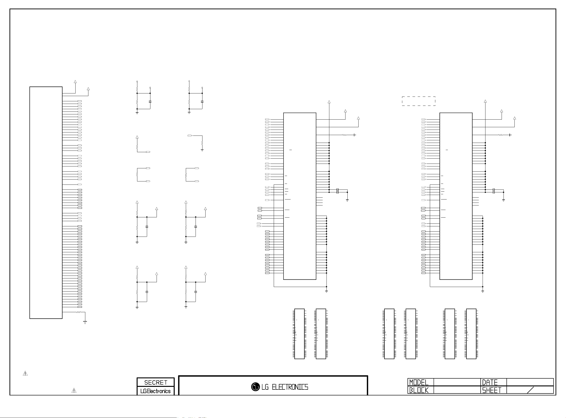
PAGE 5
Copyright ⓒ 2015 LG Electronics. Inc. All right reserved.
Only for training and service purposes
LGE Internal Use Only
IC101
LG1311
M1_DDR_U_CLKP
M1_DDR_U_CLKN
M1_DDR_D_CLKP
M1_DDR_D_CLKN
M1_DDR_RESET_N
M1_DDR_DQS_P0
M1_DDR_DQS_N0
M1_DDR_DQS_P1
M1_DDR_DQS_N1
M1_DDR_DQS_P2
M1_DDR_DQS_N2
M1_DDR_DQS_P3
M1_DDR_DQS_N3
M1_DDR_VREF1
M1_DDR_VREF2
M1_DDR_A0
M1_DDR_A1
M1_DDR_A2
M1_DDR_A3
M1_DDR_A4
M1_DDR_A5
M1_DDR_A6
M1_DDR_A7
M1_DDR_A8
M1_DDR_A9
M1_DDR_A10
M1_DDR_A11
M1_DDR_A12
M1_DDR_A13
M1_DDR_A14
M1_DDR_A15
M1_DDR_BA0
M1_DDR_BA1
M1_DDR_BA2
M1_DDR_CKE
M1_DDR_ODT
M1_DDR_RASN
M1_DDR_CASN
M1_DDR_WEN
M1_DDR_DM0
M1_DDR_DM1
M1_DDR_DM2
M1_DDR_DM3
M1_DDR_DQ0
M1_DDR_DQ1
M1_DDR_DQ2
M1_DDR_DQ3
M1_DDR_DQ4
M1_DDR_DQ5
M1_DDR_DQ6
M1_DDR_DQ7
M1_DDR_DQ8
M1_DDR_DQ9
M1_DDR_DQ10
M1_DDR_DQ11
M1_DDR_DQ12
M1_DDR_DQ13
M1_DDR_DQ14
M1_DDR_DQ15
M1_DDR_DQ16
M1_DDR_DQ17
M1_DDR_DQ18
M1_DDR_DQ19
M1_DDR_DQ20
M1_DDR_DQ21
M1_DDR_DQ22
M1_DDR_DQ23
M1_DDR_DQ24
M1_DDR_DQ25
M1_DDR_DQ26
M1_DDR_DQ27
M1_DDR_DQ28
M1_DDR_DQ29
M1_DDR_DQ30
M1_DDR_DQ31
M1_DDR_ZQCAL
VREF_M1_0
A2
Y1
M5
N5
K5
H5
T4
H4
R4
J5
T5
L5
U4
P4
P5
K4
R5
N4
G4
U5
L4
R3
R2
F3
F2
M4
F5
E4
F4
G5
J4
E2
E3
G2
G1
P2
P3
T2
T1
H1
E1
U1
P1
C2
K2
B3
J3
B1
K1
B2
K3
J2
D2
H3
C3
G3
D1
H2
D3
M2
V3
L3
W2
L1
W1
L2
W3
V2
N2
U3
M3
T3
N1
U2
N3
E5
R501
VREF_M1_1
M1_DDR_A0
M1_DDR_A1
M1_DDR_A2
M1_DDR_A3
M1_DDR_A4
M1_DDR_A5
M1_DDR_A6
M1_DDR_A7
M1_DDR_A8
M1_DDR_A9
M1_DDR_A10
M1_DDR_A11
M1_DDR_A12
M1_DDR_A13
M1_DDR_A14
M1_DDR_A15
M1_DDR_BA0
M1_DDR_BA1
M1_DDR_BA2
M1_U_CLK
M1_U_CLKN
M1_D_CLK
M1_D_CLKN
M1_DDR_CKE
M1_DDR_ODT
M1_DDR_RASN
M1_DDR_CASN
M1_DDR_WEN
M1_DDR_RESET_N
M1_DDR_DQS_N0
M1_DDR_DQS1
M1_DDR_DQS_N1
M1_DDR_DQS2
M1_DDR_DQS_N2
M1_DDR_DQS3
M1_DDR_DQS_N3
M1_DDR_DM0
M1_DDR_DM2
M1_DDR_DM3
M1_DDR_DQ0
M1_DDR_DQ1
M1_DDR_DQ2
M1_DDR_DQ3
M1_DDR_DQ4
M1_DDR_DQ5
M1_DDR_DQ6
M1_DDR_DQ7
M1_DDR_DQ8
M1_DDR_DQ9
M1_DDR_DQ10
M1_DDR_DQ11
M1_DDR_DQ12
M1_DDR_DQ13
M1_DDR_DQ14
M1_DDR_DQ15
M1_DDR_DQ16
M1_DDR_DQ17
M1_DDR_DQ18
M1_DDR_DQ19
M1_DDR_DQ20
M1_DDR_DQ21
M1_DDR_DQ22
M1_DDR_DQ23
M1_DDR_DQ24
M1_DDR_DQ25
M1_DDR_DQ26
M1_DDR_DQ27
M1_DDR_DQ28
M1_DDR_DQ29
M1_DDR_DQ30
M1_DDR_DQ31
240
1%
+1.5V_DDR
R508
R509
+1.5V_DDR
OPT
+1.5V_DDR
R504
R505
+1.5V_DDR
R506
R507
VREF_M1_0
1K 1%
1K 1%
R502
10K
100
R50 3
M1_DDR_VREFCA
1K 1%
1K 1%
M1_DDR_VREFDQ
1K 1%
0.1uF
1K 1%
C503
C501
0.1uF
M1_DDR_RESET_N
M1_D_CLK
M1_D_CLKN
C502
0.1uF
+1.5V_DDR
M1_DDR_CKE
+1.5V_DDR
+1.5V_DDR
VREF_M1_1
R515
1K 1%
R516
1K 1%
100
R51 0
M1_1_DDR_VREFCA
R511
1K 1%
R512
1K 1%
M1_1_DDR_VREFDQ
R513
1K 1%
0.1uF
R514
1K 1%
C508
C506
R517
10K
M1_U_CLK
M1_U_CLKN
C507
0.1uF
0.1uF
M1_DDR_RASNM1_DDR_DQS0
M1_DDR_CASN
M1_DDR_RESET_N
M1_DDR_DQS0
M1_DDR_DQS_N0
M1_DDR_DQS1M1_DDR_DM1
M1_DDR_DQS_N1
M1_DDR_DM0
M1_DDR_DM1
M1_DDR_DQ10
M1_DDR_DQ11
M1_DDR_DQ12
M1_DDR_DQ13
M1_DDR_DQ14
M1_DDR_DQ15
M1_DDR_A0
M1_DDR_A1
M1_DDR_A2
M1_DDR_A3
M1_DDR_A4
M1_DDR_A5
M1_DDR_A6
M1_DDR_A7
M1_DDR_A8
M1_DDR_A9
M1_DDR_A10
M1_DDR_A11
M1_DDR_A12
M1_DDR_A13
M1_DDR_A14
M1_DDR_A15
M1_DDR_BA0
M1_DDR_BA1
M1_DDR_BA2
M1_D_CLK
M1_D_CLKN
M1_DDR_CKE
M1_DDR_ODT
M1_DDR_WEN
M1_DDR_DQ0
M1_DDR_DQ1
M1_DDR_DQ2
M1_DDR_DQ3
M1_DDR_DQ4
M1_DDR_DQ5
M1_DDR_DQ6
M1_DDR_DQ7
M1_DDR_DQ8
M1_DDR_DQ9
IC501
H5TQ4G63AFR-PBC
N3
DDR3
A0
P7
4Gbit
A1
P3
DDR_512MB_HYNIX_1600_29n
A2
N2
A3
P8
A4
P2
A5
R8
A6
R2
A7
T8
A8
R3
A9
L7
A10/AP
R7
A11
N7
A12/BC
T3
A13
T7
A14
M7
A15
M2
BA0
N8
BA1
M3
BA2
J7
CK
K7
CK
K9
CKE
L2
CS
K1
ODT
J3
RAS
K3
CAS
L3
WE
T2
RESET
F3
DQSL
G3
DQSL
C7
DQSU
B7
DQSU
E7
DML
D3
DMU
E3
DQL0
F7
DQL1
F2
DQL2
F8
DQL3
H3
DQL4
H8
DQL5
G2
DQL6
H7
DQL7
D7
DQU0
C3
DQU1
C8
DQU2
C2
DQU3
A7
DQU4
A2
DQU5
B8
DQU6
A3
DQU7
IC501-*1
MT41K256M16HA-125:E
DDR_512MB_MICRON
N3
A0
P7
A1
P3
A2
N2
A3
P8
A4
P2
A5
R8
A6
R2
A7
T8
A8
R3
A9
L7
A10/AP
R7
A11
N7
A12/BC
T3
A13
M7
NC_5
M2
BA0
N8
BA1
M3
BA2
J7
CK
K7
CK
K9
CKE
L2
CS
K1
ODT
J3
RAS
K3
CAS
L3
WE
T2
RESET
F3
DQSL
G3
DQSL
C7
DQSU
B7
DQSU
E7
DML
D3
DMU
E3
DQ0
F7
DQ1
F2
DQ2
F8
DQ3
H3
DQ4
H8
DQ5
G2
DQ6
H7
DQ7
D7
DQ8
C3
DQ9
C8
DQ10
C2
DQ11
A7
DQ12
A2
DQ13
B8
DQ14
A3
DQ15
VREFCA
VREFDQ
ZQ
VDD_1
VDD_2
VDD_3
VDD_4
VDD_5
VDD_6
VDD_7
VDD_8
VDD_9
VDDQ_1
VDDQ_2
VDDQ_3
VDDQ_4
VDDQ_5
VDDQ_6
VDDQ_7
VDDQ_8
VDDQ_9
NC_1
NC_2
NC_3
NC_4
VSS_1
VSS_2
VSS_3
VSS_4
VSS_5
VSS_6
VSS_7
VSS_8
VSS_9
VSS_10
VSS_11
VSS_12
VSSQ_1
VSSQ_2
VSSQ_3
VSSQ_4
VSSQ_5
VSSQ_6
VSSQ_7
VSSQ_8
VSSQ_9
IC502-*3
MT41K128M16JT-125:K
DDR_256MB_MICRON
N3
A0
P7
A1
P3
A2
N2
A3
P8
A4
P2
A5
R8
A6
R2
A7
T8
A8
R3
A9
L7
A10/AP
R7
A11
N7
A12/BC
T3
A13
M7
NC_5
M2
BA0
N8
BA1
M3
BA2
J7
CK
K7
CK
K9
CKE
L2
CS
K1
ODT
J3
RAS
K3
CAS
L3
WE
T2
RESET
F3
DQSL
G3
DQSL
C7
DQSU
B7
DQSU
E7
DML
D3
DMU
E3
DQ0
F7
DQ1
F2
DQ2
F8
DQ3
H3
DQ4
H8
DQ5
G2
DQ6
H7
DQ7
D7
DQ8
C3
DQ9
C8
DQ10
C2
DQ11
A7
DQ12
A2
DQ13
B8
DQ14
A3
DQ15
+1.5V_DDR
M8
H1
L8
B2
D9
G7
K2
K8
N1
N9
R1
R9
A1
A8
C1
C9
D2
E9
F1
H2
H9
J1
J9
L1
L9
A9
B3
E1
G8
J2
J8
M1
M9
P1
P9
T1
T9
B1
B9
D1
D8
E2
E8
F9
G1
G9
M8
VREFCA
H1
VREFDQ
L8
ZQ
B2
VDD_1
D9
VDD_2
G7
VDD_3
K2
VDD_4
K8
VDD_5
N1
VDD_6
N9
VDD_7
R1
VDD_8
R9
VDD_9
A1
VDDQ_1
A8
VDDQ_2
C1
VDDQ_3
C9
VDDQ_4
D2
VDDQ_5
E9
VDDQ_6
F1
VDDQ_7
H2
VDDQ_8
H9
VDDQ_9
J1
NC_1
J9
NC_2
L1
NC_3
L9
NC_4
T7
NC_6
A9
VSS_1
B3
VSS_2
E1
VSS_3
G8
VSS_4
J2
VSS_5
J8
VSS_6
M1
VSS_7
M9
VSS_8
P1
VSS_9
P9
VSS_10
T1
VSS_11
T9
VSS_12
B1
VSSQ_1
B9
VSSQ_2
D1
VSSQ_3
D8
VSSQ_4
E2
VSSQ_5
E8
VSSQ_6
F9
VSSQ_7
G1
VSSQ_8
G9
VSSQ_9
M1_1_DDR_VREFCA
R519
+1.5V_DDR
C540
C541 1uF
M1_1_DDR_VREFDQ
240
1uF
DDR3 1.5V bypass Cap
: Place these caps near Memory
+1.5V_DDR
M1_DDR_VREFCA
R518
1uF
M1_DDR_VREFDQ
240
DDR3 1.5V bypass Cap
: Place these caps near Memory
H5TQ2G63FFR-PBC
DDR_256MB_HYNIX_1600_29n
N3
A0
P7
A1
P3
A2
N2
A3
P8
A4
P2
A5
R8
A6
R2
A7
T8
A8
R3
A9
L7
A10/AP
R7
A11
N7
A12/BC
T3
A13
M7
NC_5
M2
BA0
N8
BA1
M3
BA2
J7
CK
K7
CK
K9
CKE
L2
CS
K1
ODT
J3
RAS
K3
CAS
L3
WE
T2
RESET
F3
DQSL
G3
DQSL
C7
DQSU
B7
DQSU
E7
DML
D3
DMU
E3
DQL0
F7
DQL1
F2
DQL2
F8
DQL3
H3
DQL4
H8
DQL5
G2
DQL6
H7
DQL7
D7
DQU0
C3
DQU1
C8
DQU2
C2
DQU3
A7
DQU4
A2
DQU5
B8
DQU6
A3
DQU7
IC501-*2
M8
VREFCA
H1
VREFDQ
L8
ZQ
B2
VDD_1
D9
VDD_2
G7
K2
K8
N1
N9
R1
R9
A1
A8
C1
C9
D2
E9
F1
H2
H9
J1
J9
L1
L9
A9
B3
E1
G8
J2
J8
M1
M9
P1
P9
T1
T9
B1
B9
D1
D8
E2
E8
F9
G1
G9
IC502-*1
MT41K256M16HA-125:E
DDR_512MB_MICRON
N3
A0
P7
A1
P3
A2
N2
A3
P8
A4
P2
A5
R8
A6
R2
A7
T8
A8
R3
A9
L7
A10/AP
R7
A11
N7
A12/BC
T3
A13
M7
NC_5
M2
BA0
N8
BA1
M3
BA2
J7
CK
K7
CK
K9
CKE
L2
CS
K1
ODT
J3
RAS
K3
CAS
L3
WE
T2
RESET
F3
DQSL
G3
DQSL
C7
DQSU
B7
DQSU
E7
DML
D3
DMU
E3
DQ0
F7
DQ1
F2
DQ2
F8
DQ3
H3
DQ4
H8
DQ5
G2
DQ6
H7
DQ7
D7
DQ8
C3
DQ9
C8
DQ10
C2
DQ11
A7
DQ12
A2
DQ13
B8
DQ14
A3
DQ15
VREFCA
VREFDQ
VDD_1
VDD_2
VDD_3
VDD_4
VDD_5
VDD_6
VDD_7
VDD_8
VDD_9
VDDQ_1
VDDQ_2
VDDQ_3
VDDQ_4
VDDQ_5
VDDQ_6
VDDQ_7
VDDQ_8
VDDQ_9
NC_1
NC_2
NC_3
NC_4
A14
VSS_1
VSS_2
VSS_3
VSS_4
VSS_5
VSS_6
VSS_7
VSS_8
VSS_9
VSS_10
VSS_11
VSS_12
VSSQ_1
VSSQ_2
VSSQ_3
VSSQ_4
VSSQ_5
VSSQ_6
VSSQ_7
VSSQ_8
VSSQ_9
+1.5V_DDR
M8
H1
L8
ZQ
B2
D9
G7
K2
K8
N1
N9
R1
R9
A1
A8
C1
C9
D2
E9
F1
H2
H9
J1
J9
L1
L9
T7
A9
B3
E1
G8
J2
J8
M1
M9
P1
P9
T1
T9
B1
B9
D1
D8
E2
E8
F9
G1
G9
C524
C525 1uF
VDD_3
VDD_4
VDD_5
VDD_6
VDD_7
VDD_8
VDD_9
VDDQ_1
VDDQ_2
VDDQ_3
VDDQ_4
VDDQ_5
VDDQ_6
VDDQ_7
VDDQ_8
VDDQ_9
NC_1
NC_2
NC_3
NC_4
VSS_1
VSS_2
VSS_3
VSS_4
VSS_5
VSS_6
VSS_7
VSS_8
VSS_9
VSS_10
VSS_11
VSS_12
VSSQ_1
VSSQ_2
VSSQ_3
VSSQ_4
VSSQ_5
VSSQ_6
VSSQ_7
VSSQ_8
VSSQ_9
M8
VREFCA
H1
VREFDQ
L8
ZQ
B2
VDD_1
D9
VDD_2
G7
VDD_3
K2
VDD_4
K8
VDD_5
N1
VDD_6
N9
VDD_7
R1
VDD_8
R9
VDD_9
A1
VDDQ_1
A8
VDDQ_2
C1
VDDQ_3
C9
VDDQ_4
D2
VDDQ_5
E9
VDDQ_6
F1
VDDQ_7
H2
VDDQ_8
H9
VDDQ_9
J1
NC_1
J9
NC_2
L1
NC_3
L9
NC_4
T7
A14
A9
VSS_1
B3
VSS_2
E1
VSS_3
G8
VSS_4
J2
VSS_5
J8
VSS_6
M1
VSS_7
M9
VSS_8
P1
VSS_9
P9
VSS_10
T1
VSS_11
T9
VSS_12
B1
VSSQ_1
B9
VSSQ_2
D1
VSSQ_3
D8
VSSQ_4
E2
VSSQ_5
E8
VSSQ_6
F9
VSSQ_7
G1
VSSQ_8
G9
VSSQ_9
M8
VREFCA
H1
VREFDQ
L8
ZQ
B2
VDD_1
D9
VDD_2
G7
VDD_3
K2
VDD_4
K8
VDD_5
N1
VDD_6
N9
VDD_7
R1
VDD_8
R9
VDD_9
A1
VDDQ_1
A8
VDDQ_2
C1
VDDQ_3
C9
VDDQ_4
D2
VDDQ_5
E9
VDDQ_6
F1
VDDQ_7
H2
VDDQ_8
H9
VDDQ_9
J1
NC_1
J9
NC_2
L1
NC_3
L9
NC_4
T7
NC_6
A9
VSS_1
B3
VSS_2
E1
VSS_3
G8
VSS_4
J2
VSS_5
J8
VSS_6
M1
VSS_7
M9
VSS_8
P1
VSS_9
P9
VSS_10
T1
VSS_11
T9
VSS_12
B1
VSSQ_1
B9
VSSQ_2
D1
VSSQ_3
D8
VSSQ_4
E2
VSSQ_5
E8
VSSQ_6
F9
VSSQ_7
G1
VSSQ_8
G9
VSSQ_9
1_2Gbit : T7(NC_6)
4Gbit : T7(A14)
M1_DDR_A0
M1_DDR_A1
M1_DDR_A2
M1_DDR_A3
M1_DDR_A4
M1_DDR_A5
M1_DDR_A6
M1_DDR_A7
M1_DDR_A8
M1_DDR_A9
M1_DDR_A10
M1_DDR_A11
M1_DDR_A12
M1_DDR_A13
M1_DDR_A14
M1_DDR_A15
M1_DDR_BA0
M1_DDR_BA1
M1_DDR_BA2
M1_U_CLK
M1_U_CLKN
M1_DDR_CKE
M1_DDR_ODT
M1_DDR_RASN
M1_DDR_CASN
M1_DDR_WEN
M1_DDR_RESET_N
M1_DDR_DQS2
M1_DDR_DQS_N2
M1_DDR_DQS3
M1_DDR_DQS_N3
M1_DDR_DM2
M1_DDR_DM3
M1_DDR_DQ16
M1_DDR_DQ17
M1_DDR_DQ18
M1_DDR_DQ19
M1_DDR_DQ20
M1_DDR_DQ21
M1_DDR_DQ22
M1_DDR_DQ23
M1_DDR_DQ24
M1_DDR_DQ25
M1_DDR_DQ26
M1_DDR_DQ27
M1_DDR_DQ28
M1_DDR_DQ29
M1_DDR_DQ30
M1_DDR_DQ31
IC502-*2
H5TQ2G63FFR-PBC
DDR_256MB_HYNIX_1600_29n
N3
M8
A0
VREFCA
P7
A1
P3
A2
N2
H1
A3
VREFDQ
P8
A4
P2
A5
R8
L8
A6
ZQ
R2
A7
T8
A8
B2
R3
VDD_1
A9
D9
L7
VDD_2
A10/AP
G7
R7
VDD_3
A11
N7
K2
VDD_4
A12/BC
T3
K8
A13
VDD_5
N1
VDD_6
M7
N9
NC_5
VDD_7
R1
VDD_8
M2
R9
BA0
VDD_9
N8
BA1
M3
BA2
A1
VDDQ_1
J7
A8
CK
VDDQ_2
K7
C1
CK
VDDQ_3
K9
C9
CKE
VDDQ_4
D2
VDDQ_5
L2
E9
CS
VDDQ_6
K1
F1
ODT
VDDQ_7
J3
H2
RAS
VDDQ_8
K3
H9
CAS
VDDQ_9
L3
WE
J1
NC_1
T2
J9
RESET
NC_2
L1
NC_3
L9
NC_4
F3
T7
DQSL
NC_6
G3
DQSL
C7
A9
DQSU
VSS_1
B7
B3
DQSU
VSS_2
E1
VSS_3
E7
G8
DML
VSS_4
D3
J2
DMU
VSS_5
J8
VSS_6
E3
M1
DQL0
VSS_7
F7
M9
DQL1
VSS_8
F2
P1
DQL2
VSS_9
F8
P9
DQL3
VSS_10
H3
T1
DQL4
VSS_11
H8
T9
DQL5
VSS_12
G2
DQL6
H7
DQL7
B1
VSSQ_1
D7
B9
DQU0
VSSQ_2
C3
D1
DQU1
VSSQ_3
C8
D8
DQU2
VSSQ_4
C2
E2
DQU3
VSSQ_5
A7
E8
DQU4
VSSQ_6
A2
F9
DQU5
VSSQ_7
B8
G1
DQU6
VSSQ_8
A3
G9
DQU7
VSSQ_9
IC502
H5TQ4G63AFR-PBC
N3
DDR3
A0
P7
4Gbit
A1
P3
DDR_512MB_HYNIX_1600_29n
A2
N2
A3
P8
A4
P2
A5
R8
A6
R2
A7
T8
A8
R3
A9
L7
A10/AP
R7
A11
N7
A12/BC
T3
A13
T7
A14
M7
A15
M2
BA0
N8
BA1
M3
BA2
J7
CK
K7
CK
K9
CKE
L2
CS
K1
ODT
J3
RAS
K3
CAS
L3
WE
T2
RESET
F3
DQSL
G3
DQSL
C7
DQSU
B7
DQSU
E7
DML
D3
DMU
E3
DQL0
F7
DQL1
F2
DQL2
F8
DQL3
H3
DQL4
H8
DQL5
G2
DQL6
H7
DQL7
D7
DQU0
C3
DQU1
C8
DQU2
C2
DQU3
A7
DQU4
A2
DQU5
B8
DQU6
A3
DQU7
IC501-*3
MT41K128M16JT-125:K
DDR_256MB_MICRON
N3
M8
A0
VREFCA
P7
A1
P3
A2
N2
H1
A3
VREFDQ
P8
A4
P2
A5
R8
L8
A6
ZQ
R2
A7
T8
A8
B2
R3
VDD_1
A9
D9
L7
VDD_2
A10/AP
G7
R7
VDD_3
A11
N7
K2
VDD_4
A12/BC
T3
K8
A13
VDD_5
N1
VDD_6
M7
N9
NC_5
VDD_7
R1
VDD_8
M2
R9
BA0
VDD_9
N8
BA1
M3
BA2
A1
VDDQ_1
J7
A8
CK
VDDQ_2
K7
C1
CK
VDDQ_3
K9
C9
CKE
VDDQ_4
D2
VDDQ_5
L2
E9
CS
VDDQ_6
K1
F1
ODT
VDDQ_7
J3
H2
RAS
VDDQ_8
K3
H9
CAS
VDDQ_9
L3
WE
J1
NC_1
T2
J9
RESET
NC_2
L1
NC_3
L9
NC_4
F3
T7
DQSL
NC_6
G3
DQSL
C7
A9
DQSU
VSS_1
B7
B3
DQSU
VSS_2
E1
VSS_3
E7
G8
DML
VSS_4
D3
J2
DMU
VSS_5
J8
VSS_6
E3
M1
DQ0
VSS_7
F7
M9
DQ1
VSS_8
F2
P1
DQ2
VSS_9
F8
P9
DQ3
VSS_10
H3
T1
DQ4
VSS_11
H8
T9
DQ5
VSS_12
G2
DQ6
H7
DQ7
B1
VSSQ_1
D7
B9
DQ8
VSSQ_2
C3
D1
DQ9
VSSQ_3
C8
D8
DQ10
VSSQ_4
C2
E2
DQ11
VSSQ_5
A7
E8
DQ12
VSSQ_6
A2
F9
DQ13
VSSQ_7
B8
G1
DQ14
VSSQ_8
A3
G9
DQ15
VSSQ_9
THE SYMBOL MARK OF THIS SCHEMETIC DIAGRAM INCORPORATES
SPECIAL FEATURES IMPORTANT FOR PROTECTION FROM X-RADIATION.
FIRE AND ELECTRICAL SHOCK HAZARDS, WHEN SERVICING IF IS
ESSENTIAL THAT ONLY MANUFACTURES SPECIFIED PARTS BE USED FOR
THE CRITICAL COMPONENTS IN THE SYMBOL MARK OF THE SCHEMETIC.
MID_LG1311
M14 DDR3-M1
2013.04.04
5
31
Page 36
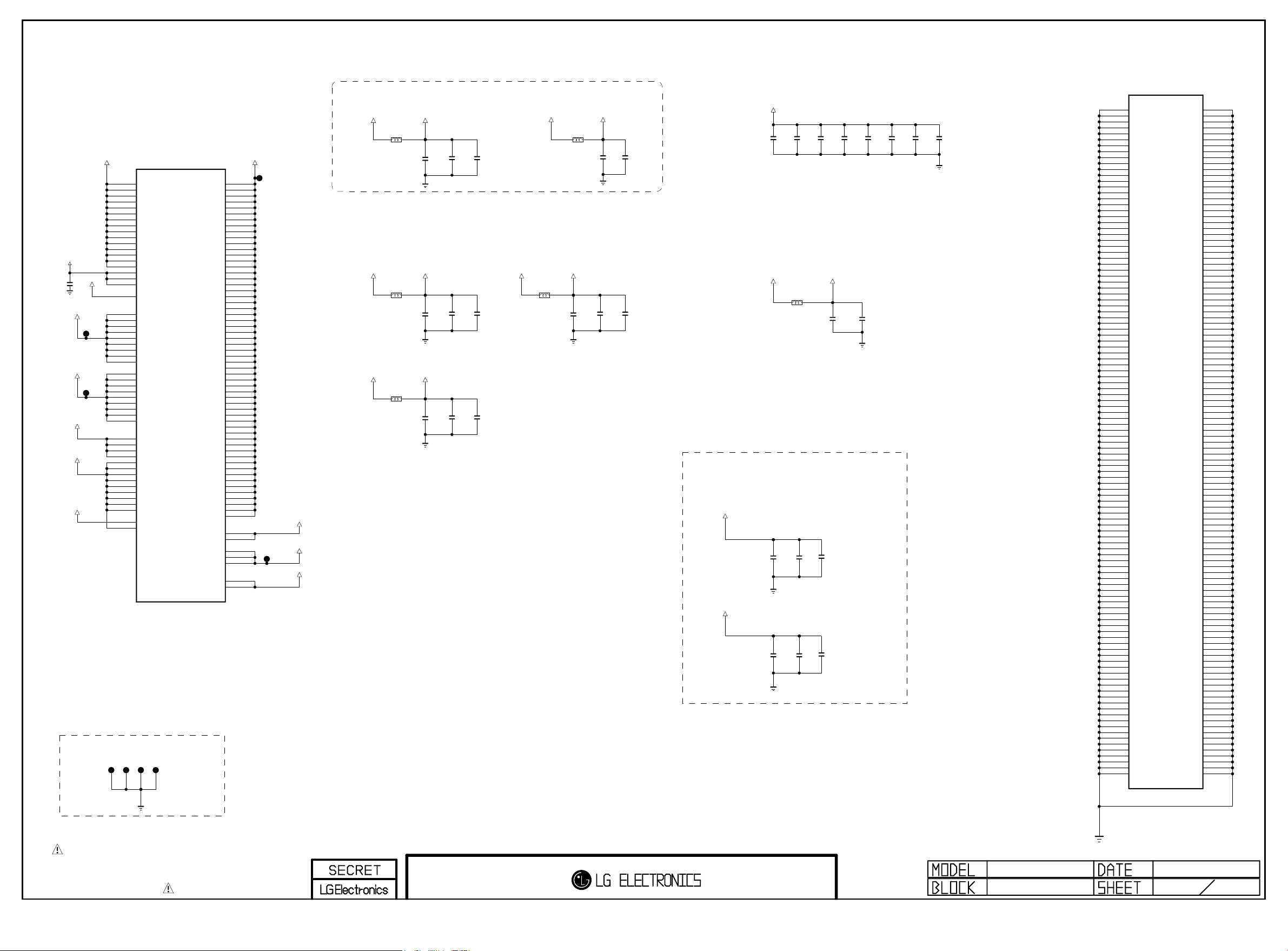
PAGE 6
Copyright ⓒ 2015 LG Electronics. Inc. All right reserved.
Only for training and service purposes
LGE Internal Use Only
VDD3V3_HDMI
AVDD33
C637
0.1uF
16V
+1.5V_DDR
+1.5V_DDR
AVDD25_C4TX
AVDD25
AVDD25_AUD
GND JIG POINT
DVDD33
TP5207
TP5208
JP601
AA23
AC12
AC13
AC14
AC15
AC11
AF22
AA11
AC18
AC19
AC20
AC21
AC22
AC23
AC17
AB23
L18
L21
L22
L23
M23
T11
Y23
P23
R23
T23
U23
V23
F10
F11
F12
F13
F14
F15
F16
F17
V11
W11
Y11
G19
H19
H20
JP602
F9
G6
H6
J6
K6
L6
M6
N6
P6
R6
IC101
LG1311
DVDD33_1
DVDD33_2
DVDD33_3
DVDD33_4
DVDD33_5
DVDD33_6
DVDD33_7
DVDD33_8
DVDD33_9
DVDD33_10
DVDD33_11
DVDD33_12
AVDD33_BT_USB
AVDD33_USB_1
AVDD33_USB_2
AVDD33_HDMI_1
AVDD33_HDMI_2
AVDD33_HDMI_3
AVDD33_CVBS
DVDD15_M0_1
DVDD15_M0_2
DVDD15_M0_3
DVDD15_M0_4
DVDD15_M0_5
DVDD15_M0_6
DVDD15_M0_7
DVDD15_M0_8
DVDD15_M0_9
DVDD15_M1_1
DVDD15_M1_2
DVDD15_M1_3
DVDD15_M1_4
DVDD15_M1_5
DVDD15_M1_6
DVDD15_M1_7
DVDD15_M1_8
DVDD15_M1_9
AVDD25_C4TX_1
AVDD25_C4TX_2
AVDD25_C4TX_3
AVDD25_C4TX_4
AVDD25_COMP_1
AVDD25_COMP_2
AVDD25_CVBS_1
AVDD25_CVBS_2
AVDD25_DMD
AVDD25_AAD
DVDD25_XTAL
AVDD25_DR3PLL
SP_VQPS
AVDD25_AUD
AVDD25_APLL
JP604
JP603
DVDD11_1
DVDD11_2
DVDD11_3
DVDD11_4
DVDD11_5
DVDD11_6
DVDD11_7
DVDD11_8
DVDD11_9
DVDD11_10
DVDD11_11
DVDD11_12
DVDD11_13
DVDD11_14
DVDD11_15
DVDD11_16
DVDD11_17
DVDD11_18
DVDD11_19
DVDD11_20
DVDD11_21
DVDD11_22
DVDD11_23
DVDD11_24
DVDD11_25
DVDD11_26
DVDD11_27
DVDD11_28
DVDD11_29
DVDD11_30
DVDD11_31
DVDD11_32
DVDD11_33
DVDD11_34
DVDD11_35
DVDD11_36
DVDD11_37
DVDD11_38
DVDD11_39
DVDD11_40
DVDD11_41
DVDD11_42
DVDD11_43
DVDD11_44
DVDD11_45
DVDD11_46
DVDD11_47
DVDD11_48
DVDD11_49
DVDD11_50
DVDD11_51
AVDD11_APLL
AVDD11_COMP_LLPLL
AVDD11_C4TX_1
AVDD11_C4TX_2
AVDD11_C4TX_3
AVDD11_C4TX_4
DVDD11_XTAL
DVDD11_DR3PLL
DVDD11_CVBSPLL
AVDD11_DMD_1
AVDD11_DMD_2
DVDD18_EMMC_1
DVDD18_EMMC_2
+1.1V_VDD
M20
M21
N13
N14
N15
N16
N17
N18
P20
P21
R13
R14
R15
R16
R17
R18
R19
R20
R21
T13
T20
T21
U14
U15
U16
U17
U18
U19
U20
U21
V13
V20
V21
W13
W14
W15
W16
W17
W18
W19
Y13
Y20
Y21
AA13
AA14
AA15
AA17
AA18
AA19
AA20
AA21
AB21
AB19
V12
W12
Y12
AA12
G18
H18
AF23
AF24
AF25
L26
M26
TP5209
+1.1V_VDD
AVDD11_DMD
TP5210
DVDD18_EMMC
+3.3V_Bypass Cap
+3.3V_NORMAL
L601
BLM18PG121SN1D
C601
4.7uF
+2.5V_Bypass Cap
+2.5V_NORMAL
L602
BLM18PG121SN1D
C602
4.7uF
+2.5V_NORMAL
AVDD25_AUD
L603
BLM18PG121SN1D
C603
4.7uF
DVDD33
10V
AVDD25
10V
10V
C604
4.7uF
C605
4.7uF
C606
4.7uF
B22
B24
C22
C23
C24
D4
D5
D6
D20
D21
E6
E20
E21
F6
F7
F8
F18
F19
F20
F21
G7
G8
G9
G10
G11
G12
G13
G14
G15
G16
G17
G20
G21
G22
G23
G24
G25
G26
G27
H7
H8
H9
H10
H11
H12
H13
H14
H15
H16
H17
H21
H22
H23
H24
H25
H26
H27
H31
J7
J8
J26
J27
K7
K8
K26
K27
L7
L8
L11
L12
L13
L14
L15
L16
L17
L19
L20
L27
M7
M8
M11
M12
M13
M14
M15
M16
M17
M18
M19
M22
M27
N7
N8
N11
N12
N19
N20
N21
N22
N23
N26
N27
N30
P7
P8
P11
P12
P13
P14
P15
P16
P17
P18
IC101
LG1311
GND_1
GND_2
GND_3
GND_4
GND_5
GND_6
GND_7
GND_8
GND_9
GND_10
GND_11
GND_12
GND_13
GND_14
GND_15
GND_16
GND_17
GND_18
GND_19
GND_20
GND_21
GND_22
GND_23
GND_24
GND_25
GND_26
GND_27
GND_28
GND_29
GND_30
GND_31
GND_32
GND_33
GND_34
GND_35
GND_36
GND_37
GND_38
GND_39
GND_40
GND_41
GND_42
GND_43
GND_44
GND_45
GND_46
GND_47
GND_48
GND_49
GND_50
GND_51
GND_52
GND_53
GND_54
GND_55
GND_56
GND_57
GND_58
GND_59
GND_60
GND_61
GND_62
GND_63
GND_64
GND_65
GND_66
GND_67
GND_68
GND_69
GND_70
GND_71
GND_72
GND_73
GND_74
GND_75
GND_76
GND_77
GND_78
GND_79
GND_80
GND_81
GND_82
GND_83
GND_84
GND_85
GND_86
GND_87
GND_88
GND_89
GND_90
GND_91
GND_92
GND_93
GND_94
GND_95
GND_96
GND_97
GND_98
GND_99
GND_100
GND_101
GND_102
GND_103
GND_104
GND_105
GND_106
GND_107
GND_108
GND_109
GND_110
GND_111
GND_112
GND_113
GND_114
GND_115
GND_116
GND_117
GND_118
GND_119
GND_120
GND_121
GND_122
GND_123
GND_124
GND_125
GND_126
GND_127
GND_128
GND_129
GND_130
GND_131
GND_132
GND_133
GND_134
GND_135
GND_136
GND_137
GND_138
GND_139
GND_140
GND_141
GND_142
GND_143
GND_144
GND_145
GND_146
GND_147
GND_148
GND_149
GND_150
GND_151
GND_152
GND_153
GND_154
GND_155
GND_156
GND_157
GND_158
GND_159
GND_160
GND_161
GND_162
GND_163
GND_164
GND_165
GND_166
GND_167
GND_168
GND_169
GND_170
GND_171
GND_172
GND_173
GND_174
GND_175
GND_176
GND_177
GND_178
GND_179
GND_180
GND_181
GND_182
GND_183
GND_184
GND_185
GND_186
GND_187
GND_188
GND_189
GND_190
GND_191
GND_192
GND_193
GND_194
GND_195
GND_196
GND_197
GND_198
GND_199
GND_200
GND_201
GND_202
GND_203
GND_204
GND_205
GND_206
GND_207
GND_208
GND_209
GND_210
GND_211
GND_212
GND_213
GND_214
GND_215
GND_216
GND_217
GND_218
GND_219
GND_220
GND_221
GND_222
GND_223
GND_224
GND_225
GND_226
P19
P22
P26
P30
R7
R8
R11
R12
R22
R26
R27
T6
T7
T8
T12
T14
T15
T16
T17
T18
T19
T22
T26
T27
U6
U7
U8
U11
U12
U13
U22
U26
V4
V5
V6
V7
V8
V14
V15
V16
V17
V18
V19
V22
V26
V30
V31
W4
W8
W20
W21
W22
W23
W26
W27
Y2
Y3
Y4
Y8
Y14
Y15
Y16
Y17
Y18
Y19
Y22
Y26
AA8
AA16
AA22
AA26
AB11
AB12
AB13
AB14
AB15
AB16
AB17
AB18
AB20
AB22
AB26
AB30
AB31
AC16
AC26
AD26
AE26
AF6
AF8
AF9
AF10
AF11
AF12
AF13
AF14
AF15
AF16
AF17
AF18
AF19
AF20
AF21
AF26
AG20
AG25
AG31
AH25
AJ25
AK9
AK25
AL9
AL15
+1.1V_Bypass Cap
+3.3V_NORMAL
C607
0.1uF
16V
10V
L606
BLM18PG121SN1D
C614
4.7uF
AVDD33
10V
C615
0.1uF
16V
AFE 3CH Power
+2.5V_NORMAL
C608
0.1uF
10V
16V
C609
0.1uF
10V
16V
AVDD25_C4TX
L604
BLM18PG121SN1D
C610
0.1uF
16V
C613
4.7uF
C616
0.1uF
10V
16V
+1.1V_VDD
C618
C617
4.7uF
4.7uF
10V
+1.1V_VDD
BLM18PG121SN1D
10V
L607
C619
4.7uF
10V
AVDD11_DMD
C622
4.7uF
10V
C620
4.7uF
10V
C625
0.1uF
C623
4.7uF
16V
C626
0.1uF
10V
16V
0.1uF
0.1uF
16V
16V
C628
C627
+1.5V_Bypass Cap
+1.5V_DDR
OPT
C631
+1.5V_DDR
C629
22uF
10V
OPT
C630
22uF
10V
0.1uF
16V
C632
0.1uF
16V
C633
0.1uF
16V
C634
0.1uF
16V
THE SYMBOL MARK OF THIS SCHEMETIC DIAGRAM INCORPORATES
SPECIAL FEATURES IMPORTANT FOR PROTECTION FROM X-RADIATION.
FIRE AND ELECTRICAL SHOCK HAZARDS, WHEN SERVICING IF IS
ESSENTIAL THAT ONLY MANUFACTURES SPECIFIED PARTS BE USED FOR
THE CRITICAL COMPONENTS IN THE SYMBOL MARK OF THE SCHEMETIC.
11/05/31
MID_LG1311
VCC & GND
2013.04.04
6
31
Page 37
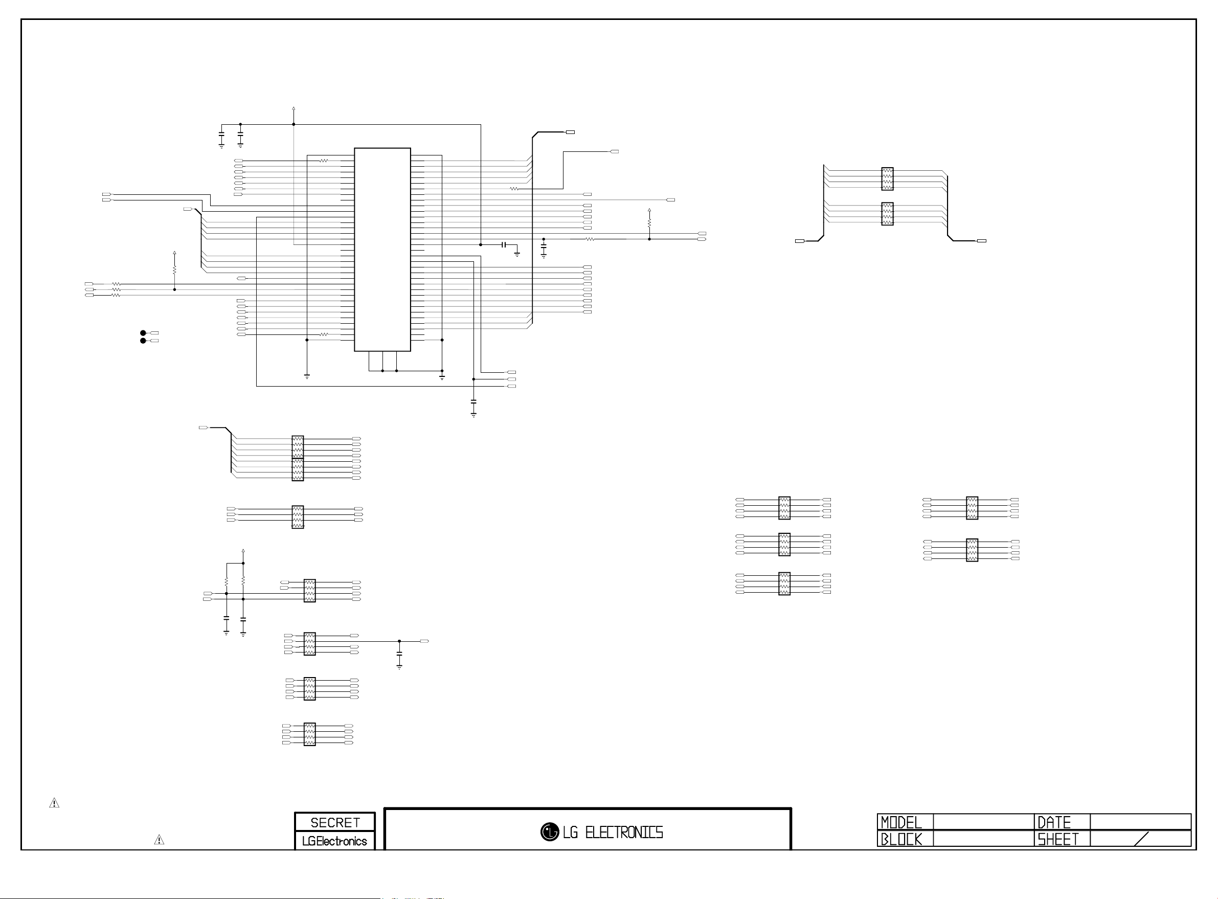
PCM_RESET
Copyright ⓒ 2015 LG Electronics. Inc. All right reserved.
Only for training and service purposes
LGE Internal Use Only
/PCM_WAIT
PCM_INPACK
/PCM_IORD
/PCM_IOWR
R702
R703
R701
CI_IN_TS_DATA[0-7]
CI
33
CI
33
OPT
33
+5V_CI_ON
PCM_INPACK
/PCM_CE2
10K
R707
CI
C701
0.1uF
CI
/CI_CD1
CI_TS_DATA[3]
CI_TS_DATA[4]
CI_TS_DATA[5]
CI_TS_DATA[6]
CI_TS_DATA[7]
/PCM_CE2
CI_IN_TS_DATA[0]
CI_IN_TS_DATA[1]
CI_IN_TS_DATA[2]
CI_IN_TS_DATA[3]
CI_IN_TS_DATA[4]
CI_IN_TS_DATA[5]
CI_IN_TS_DATA[6]
CI_IN_TS_DATA[7]
CI_TS_CLK
/PCM_REG
CI_TS_VAL
CI_TS_SYNC
CI_TS_DATA[0]
CI_TS_DATA[1]
CI_TS_DATA[2]
/CI_CD2
C702
4.7uF
10V
CI
+5V_CI_ON
R715
CI
R716 100
PAGE 7
C705
0.1uF
16V
CI_ADDR[12]
CI_ADDR[7]
CI_ADDR[6]
CI_ADDR[5]
CI_ADDR[4]
CI_ADDR[3]
CI_ADDR[2]
CI_ADDR[1]
CI_ADDR[0]
CI_DATA[0-7]
R721 33
OPT
CI_ADDR[10]
CI_ADDR[11]
CI_ADDR[9]
CI_ADDR[8]
CI_ADDR[13]
CI_ADDR[14]
CI_ADDR[12]
CI_ADDR[7]
CI_ADDR[6]
CI_ADDR[5]
CI_ADDR[4]
CI_ADDR[3]
CI_ADDR[2]
CI_ADDR[1]
CI_ADDR[0]
/PCM_CE1
+5V_CI_ON
R722
10K
CI
CI_DATA[0]
CI_DATA[1]
CI_DATA[2]
CI_DATA[3]
/PCM_OE
CI
/PCM_WE
/PCM_IRQA
CI_DATA[0-7]
CI_DATA[4]
CI_DATA[5]
CI_DATA[6]
CI_DATA[7]
AR713
33
CI
AR714
33
EB_DATA[0]
EB_DATA[1]
EB_DATA[2]
EB_DATA[3]
EB_DATA[4]
EB_DATA[5]
EB_DATA[6]
EB_DATA[7]
EB_DATA[0-7]
EB_DATA[0-7]
CI
JK701
10125901-015LF
35
100
36
CI
37
38
39
40
41
42
43
44
45
46
47
48
49
50
51
52
53
54
55
56
57
58
59
65
66
67
68
1
2
3
4
5
6
7
8
9
10
11
12
13
14
15
16
17
18
19
20
21
22
23
24
25
2660
2761
2862
2963
3064
31
32
33
34
G1G2
69
CI_DATA[3]
CI_DATA[4]
CI_DATA[5]
CI_DATA[6]
CI_DATA[7]
CI
R720 33
C704 0.1uF
CI_DATA[0]
CI_DATA[1]
CI_DATA[2]
CI_ADDR[10]
CI_ADDR[11]
CI_ADDR[9]
CI_ADDR[8]
CI_ADDR[13]
CI_ADDR[14]
CI
CI
TPO_DATA[0-7]
/CI_CD2
/CI_CD1
TPO_CLK
TPO_SOP
TPO_VAL
+5V_NORMAL
CI
10K
R725
CI
C706
0.1uF
16V
TPO_DATA[0]
TPO_DATA[1]
TPO_DATA[2]
TPO_DATA[3]
TPO_DATA[4]
TPO_DATA[5]
TPO_DATA[6]
TPO_DATA[7]
CI
10K
/PCM_WAIT
R726
/PCM_IRQA
CI
C707
0.1uF
16V
PCM_INPACK
CI_TS_VAL
CI_TS_SYNC
CI_TS_DATA[7]
CI_TS_DATA[6]
CI_TS_DATA[5]
CI_TS_DATA[4]
CI_TS_CLK
CI_IN_TS_VAL
CI_IN_TS_CLK
CI_IN_TS_SYNC
C703
12pF
50V
OPT
CI
AR701
33
CI
AR702
33
CI
AR703
33
AR704
CI
100
AR705
CI
100
AR706
CI
100
CI_IN_TS_DATA[0]
CI_IN_TS_DATA[1]
CI_IN_TS_DATA[2]
CI_IN_TS_DATA[3]
CI_IN_TS_DATA[4]
CI_IN_TS_DATA[5]
CI_IN_TS_DATA[6]
CI_IN_TS_DATA[7]
CI_IN_TS_CLK
CI_IN_TS_SYNC
CI_IN_TS_VAL
CAM_WAIT_N
CAM_IREQ_N
CAM_CD2_N
CAM_CD1_N
CAM_INPACK_N
TPI_VAL
TPI_SOP
TPI_DATA[7]
TPI_DATA[6]
TPI_DATA[5]
TPI_DATA[4]
C708
12pF
50V
OPT
TPI_CLK
CI_ADDR[0]
CI_ADDR[1]
CI_ADDR[2]
CI_ADDR[3]
CI_ADDR[4]
CI_ADDR[5]
CI_ADDR[6]
CI_ADDR[7]
CI_ADDR[8]
CI_ADDR[9]
CI_ADDR[10]
CI_ADDR[11]
CI
AR709
33
CI
AR710
33
CI
AR711
33
EB_ADDR[0]
EB_ADDR[1]
EB_ADDR[2]
EB_ADDR[3]
EB_ADDR[4]
EB_ADDR[5]
EB_ADDR[6]
EB_ADDR[7]
EB_ADDR[8]
EB_ADDR[9]
EB_ADDR[10]
EB_ADDR[11]
CI_ADDR[12]
CI_ADDR[13]
CI_ADDR[14]
/PCM_REG
/PCM_OE
/PCM_WE
/PCM_IORD
/PCM_IOWR
CI
AR712
33
CI
AR708
33
EB_ADDR[12]
EB_ADDR[13]
EB_ADDR[14]
CAM_REG_N
EB_OE_N
EB_WE_N
EB_BE_N1
EB_BE_N0
THE SYMBOL MARK OF THIS SCHEMETIC DIAGRAM INCORPORATES
SPECIAL FEATURES IMPORTANT FOR PROTECTION FROM X-RADIATION.
FIRE AND ELECTRICAL SHOCK HAZARDS, WHEN SERVICING IF IS
ESSENTIAL THAT ONLY MANUFACTURES SPECIFIED PARTS BE USED FOR
THE CRITICAL COMPONENTS IN THE SYMBOL MARK OF THE SCHEMETIC.
CI_TS_DATA[3]
CI_TS_DATA[2]
CI_TS_DATA[1]
CI_TS_DATA[0]
AR707
CI
100
TPI_DATA[3]
TPI_DATA[2]
TPI_DATA[1]
TPI_DATA[0]
MID_LG1311
PCMCIA
2013.03.22
7
31
Page 38
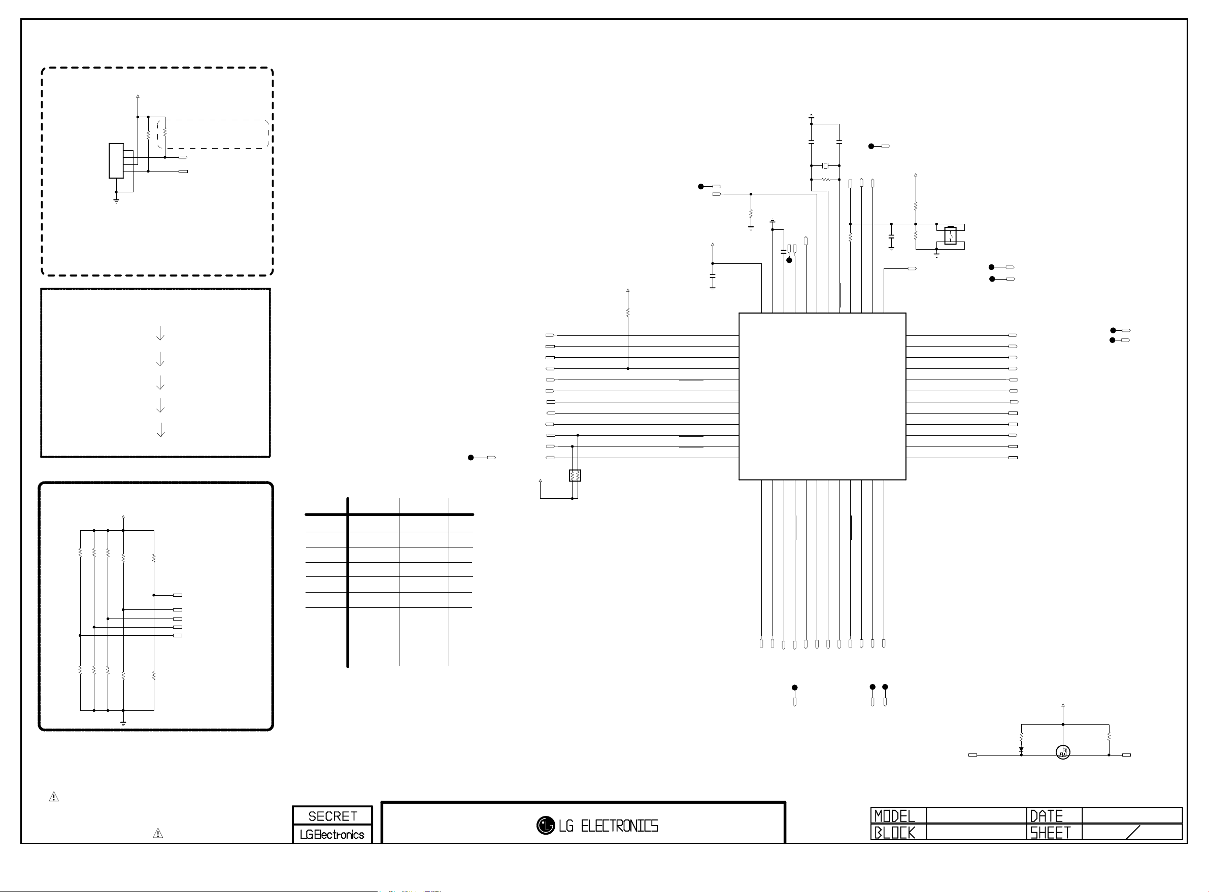
Renesas MICOM
Copyright ⓒ 2015 LG Electronics. Inc. All right reserved.
Only for training and service purposes
LGE Internal Use Only
For Debug
+3.5V_ST
PAGE 9
MICOM_DEBUG
P3000
12507WS-04L
5
1
2
3
4
Don’t remove R3016,
not making float P40
R3016 1K
R3014 10K
MICOM_DEBUG
M14 Power SEQUENCE
POWER_ON/OFF1
POWER_ON/OFF2_4
POWER_ON/OFF2_2
POWER_ON/OFF2_3
POWER_ON/OFF2_1
SOC_RESET
MICOM MODEL OPTION
+3.5V_ST
MICOM_EPI
MICOM_GED
R3003 10K
R3006 10K
R3002 10K
MICOM_H13/H14
R3007 10K
MICOM_OLED
R3013 10K
MICOM_LOGO_LIGHT
MICOM_DEBUG
MICOM_RESET
MODEL1_OPT_0
MODEL1_OPT_1
MODEL1_OPT_2
MODEL1_OPT_3
MODEL1_OPT_4
MICOM MODEL OPTION
1
LOGO
OLED
EPI
H13/H14
GED
MODEL_OPT_0
MODEL_OPT_1
MODEL_OPT_2
MODEL_OPT_3
MODEL_OPT_4
0
NON LOGO
LCD/UHD
NON_EPI
M14
NON_GED
TP3002
I2C_SCL_MICOM_SOC
I2C_SDA_MICOM_SOC
MODEL1_OPT_4
PANEL_CTL
WOL/WIFI_POWER_ON
HDMI_CEC
POWER_ON/OFF2_2
POWER_ON/OFF2_3
EYE_SDA
EYE_SCL
CAM_SLEEP
CAM_SLEEP
IR
+3.5V_ST
AR3000
3.3K
+3.5V_ST
R3021
10K
P31/TI03/TO03/INTP4
P75/KR5/INTP9/SCK01/SCL01
P74/KR4/INTP8/SI01/SDA01
P71/KR1/SI21/SDA21
P70/KR0/SCK21/SCL21
P30/INTP3/RTC1HZ/SCK11/SCL11
1/16W
HDMI_WAUP:HDMI_INIT
+3.5V_ST
MHL_DET
C3000
0.1uF
MHL_DET
P60/SCLA0
P61/SDAA0
P62
P63
P73/KR3/SO01
P72/KR2/SO21
50V
10pF
C3002
X3000
32.768KHz
10K
GND
R3032
MODULE_20V_DET
CAM_PWR_ON_CMD
CAM_PWR_ON_CMD
C3001 0.47uF
TP3009
P137/INTP0
P122/X2/EXCLK
P121/X1
REGC
VSS
VDD
43
44
45
46
47
48
1
2
3
4
5
6
IC3000
R5F100GEAFB#30
7
8
9
10
11
12
13
14
15
16
17
18
P17/TI02/TO02
P51/INTP2/SO11
P16/TI01/TO01/INTP5
P50/INTP1/SI11/SDA11
P14/RXD2/SI20/SDA20
P15/PCLBUZ1/SCK20/SCL20
50V
12pF
C3003
R3028
MICOM_RESET
4.7M
OPT
R3029 33
P40/TOOL0
RESET
P124/XT2/EXCLKS
P123/XT1
40
41
42
19
20
21
LOGO_LIGHT
MICOM_DEBUG
LOGO_LIGHT
C3004
0.1uF
16V
P120/ANI19
P41/TI07/TO07
37
38
39
36
35
34
33
32
31
30
29
28
27
26
25
22
23
24
+3.5V_ST
10K
R3030
R3031
P140/PCLBUZ0/INTP6
P00/TI00/TXD1
P01/TO00/RXD1
P130
P20/ANI0/AVREFP
P21/ANI1/AVREFM
P22/ANI2
P23/ANI3
P24/ANI4
P25/ANI5
P26/ANI6
P27/ANI7
P146
P147/ANI18
P13/TXD2/SO20
P10/SCK00/SCL00
P12/SO00/TXD0/TOOLTXD
P11/SI00/RXD0/TOOLRXD/SDA00
OPT
270K
CAM_RESET
MICOM_RESET_SW
SW3000
JTP-1127WEM
12
4 3
CAM_RESET
MODULE_20V_DET
RL_ON
SCART_MUTE
POWER_ON/OFF2_4
POWER_ON/OFF2_1
KEY2
KEY1
EPI_CTL
MODEL1_OPT_3
MODEL1_OPT_0
SIDE_HP_MUTE
MODEL1_OPT_2
MODEL1_OPT_1
SCART_MUTE
POWER_ON/OFF2_4
MICOM_M14
R3000 10K
R3004 10K
R3001 10K
MICOM_NON_GED
MICOM_NON_EPI
R3005 10K
MICOM_LCD/UHD
R3012 10K
MICOM_NON_LOGO_LIGHT
THE SYMBOL MARK OF THIS SCHEMETIC DIAGRAM INCORPORATES
SPECIAL FEATURES IMPORTANT FOR PROTECTION FROM X-RADIATION.
FIRE AND ELECTRICAL SHOCK HAZARDS, WHEN SERVICING IF IS
ESSENTIAL THAT ONLY MANUFACTURES SPECIFIED PARTS BE USED FOR
THE CRITICAL COMPONENTS IN THE SYMBOL MARK OF THE SCHEMETIC.
POWER_DET
POWER_ON/OFF1
WOL/ETH_POWER_ON
LED_R
LED_R
WOL_CTL
INV_CTL
SOC_RESET
SOC_TX
SOC_RX
EDID_WP
AMP_MUTE
EDID_WP
CAM_CTL
CAM_CTL
CEC_REMOTE
MID_LG1311
MICOM
D3000
BAT54_SUZHO
For CEC
R3033
27K
+3.5V_ST
G
D
S
Q3001
RUE003N02
R3034
120K
HDMI_CEC
2013.03.22
9
31
Page 39
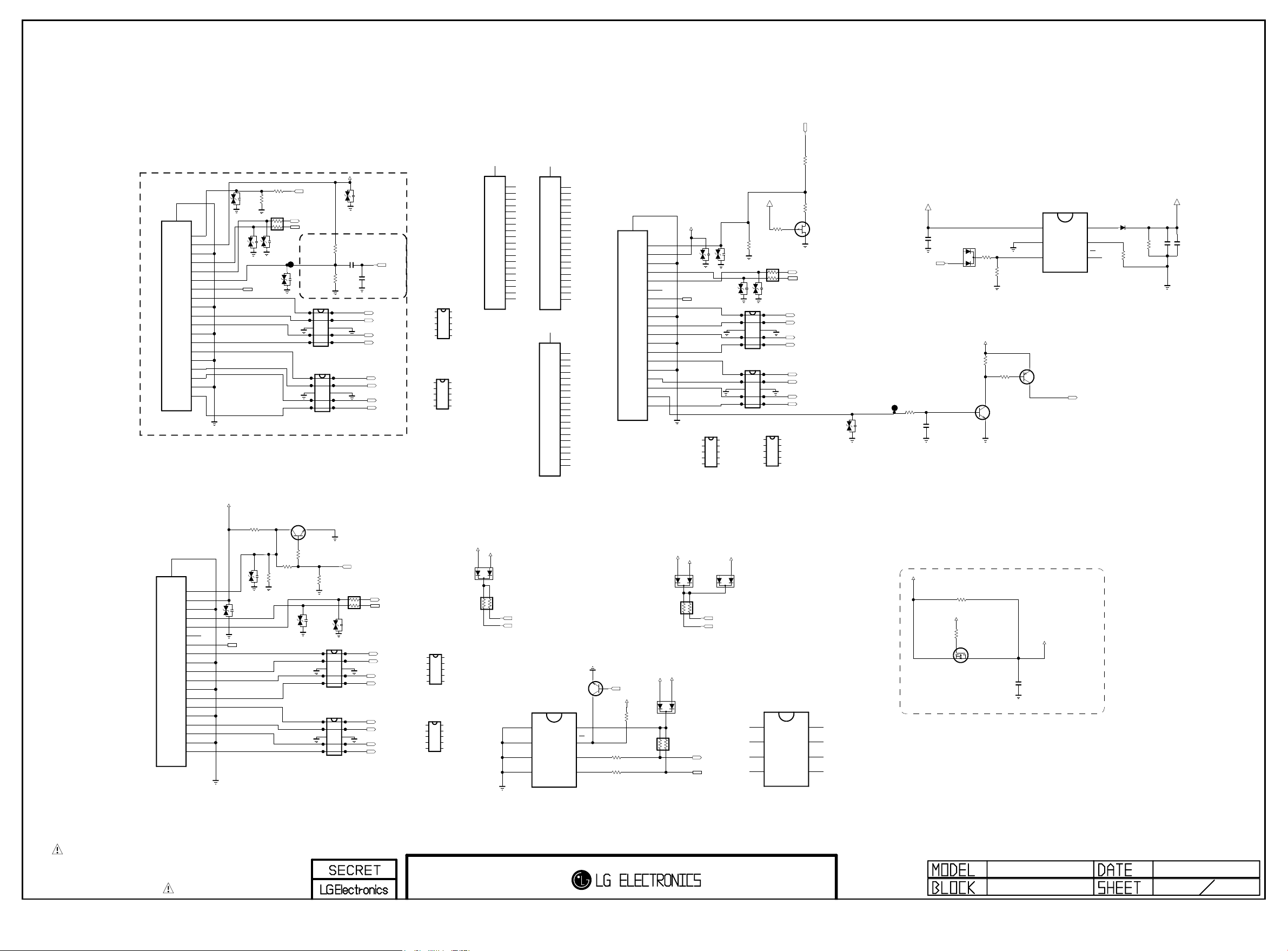
BODY_SHIELD
Copyright ⓒ 2015 LG Electronics. Inc. All right reserved.
Only for training and service purposes
LGE Internal Use Only
20
EAG63530101
JK3202
DAADR019A
HDMI_JACK_FOOSUNG
BODY_SHIELD
20
19
18
17
16
15
14
13
12
11
10
9
8
EAG63530101
7
6
5
4
3
2
1
JK3200
DAADR019A
HDMI_JACK_FOOSUNG
19
18
17
16
15
14
13
12
11
10
9
8
7
6
5
4
3
2
1
HP_DET
5V
GND
DDC_DATA
DDC_CLK
NC
CE_REMOTE
CK-
CK_GND
CK+
D0-
D0_GND
D0+
D1-
D1_GND
D1+
D2-
D2_GND
D2+
HP_DET
5V
GND
DDC_DATA
DDC_CLK
ARC
CE_REMOTE
CK-
CK_GND
CK+
D0-
D0_GND
D0+
D1-
D1_GND
D1+
D2-
D2_GND
D2+
VA3206
ESD_HDMI
5V_HDMI_2
VA3208
ESD_HDMI
CEC_REMOTE
HDMI_EXT_EDID
1K
R3268
ESD_HDMI
VA3209
ESD_HDMI
CEC_REMOTE
R3265
100K
VA3213
ESD_HDMI
VA3205
100K
33
R3250
AR3200
33
1/16W
ESD_HDMI
VA3207
HDMI_HPD_1
DDC_SCL_1
DDC_SDA_1
D3210
IP4294CZ10-TBR
1
2
3
4
5
ESD_HDMI_TMDS
D3211
IP4294CZ10-TBR
1
2
3
4
5
ESD_HDMI_TMDS
HDMI1 With ARC
HDMI_EXT_EDID
Q3206
MMBT3904(NXP)
E
C
B
1K
R3251
33
R3269
HDMI_INT_EDID
R3266
HDMI_EXT_EDID
VA3203
ESD_HDMI
1
2
3
4
5
ESD_HDMI_TMDS
1
2
3
4
5
ESD_HDMI_TMDS
5V_HDMI_1
VA3215
ESD_HDMI
R3248
1K
OPT
C3202
1uF
10V
R3249
3.9K
OPT
10
9
8
7
6
10
9
8
7
6
HDMI_HPD_2
HDMI_EXT_EDID
R3270
4.7K
AR3201
33
1/16W
VA3204
ESD_HDMI
D3212
IP4294CZ10-TBR
10
9
8
7
6
D3213
IP4294CZ10-TBR
10
9
8
7
6
HDMI2
ARC
SPDIF_OUT_ARC
OPT
C3226
0.1uF
16V
CK-_HDMI1
CK+_HDMI1
D0-_HDMI1
D0+_HDMI1
D1-_HDMI1
D1+_HDMI1
D2-_HDMI1
D2+_HDMI1
DDC_SCL_2
DDC_SDA_2
CK-_HDMI2
CK+_HDMI2
D0-_HDMI2
D0+_HDMI2
D1-_HDMI2
D1+_HDMI2
D2-_HDMI2
D2+_HDMI2
D3210-*1
IP4294CZ10-TBR
@volta
1
2
3
4
5
ESD_HDMI_TVS
D3211-*1
IP4294CZ10-TBR
@volta
1
2
3
4
5
ESD_HDMI_TVS
D3212-*1
IP4294CZ10-TBR
@volta
1
2
3
4
5
ESD_HDMI_TVS
D3213-*1
IP4294CZ10-TBR
@volta
1
2
3
4
5
ESD_HDMI_TVS
PAGE 10
HDMI_HPD_4
R3261
0
20
19
18
17
16
15
14
13
12
11
10
9
8
7
6
5
4
3
2
AR3204
47K
5501-56219
HDMI_JACK_CNPLUS
5V_HDMI_1
1/16W
JK3202-*1
A2CA1
1
DDC_SDA_1
DDC_SCL_1
10
9
8
7
6
10
9
8
7
6
+5V_NORMAL
D3200
10
9
8
7
6
10
9
8
7
6
HDMI_JACK_CNPLUS
M24C02-RMN6T
E0
1
E1
2
E2
3
VSS
4
HDMI_EXT_EDID_ST
20
19
18
17
16
15
14
13
12
11
10
9
8
7
6
5
4
3
2
1
5501-56219
JK3203-*1
HDMI_JACK_CNPLUS
20
19
18
17
16
15
14
13
12
11
10
9
8
7
6
5
4
3
2
1
5501-56219
JK3200-*1
HDMI_EXT_EDID
MMBT3904(NXP)
IC3203
Q3203
8
7
6
5
E
C
VCC
WC
SCL
SDA
BODY_SHIELD
GND
EAG63530101
DAADR019A
JK3203
HDMI_JACK_FOOSUNG
EDID_WP
B
+3.5V_ST
R3258
33
HDMI_EXT_EDID
R3259
33
HDMI_EXT_EDID
20
HP_DET
19
5V
18
GND
17
DDC_DATA
16
DDC_CLK
15
NC
14
CE_REMOTE
13
CK-
12
CK_GND
11
CK+
10
D0-
9
D0_GND
8
D0+
7
D1-
6
D1_GND
5
D1+
4
D2-
3
D2_GND
2
D2+
1
5V_HDMI_2
HDMI_EXT_EDID
R3271
4.7K
AR3206
47K
1/16W
+5V_NORMAL
D3203
AR3205
47K
+5V_NORMAL
5V_HDMI_4
5V_HDMI_4
1/16W
A2CA1
MMBD6100
D3216
VA3216
ESD_HDMI
CEC_REMOTE
D3215-*1
IP4294CZ10-TBR
@volta
1
2
3
4
5
ESD_HDMI_TVS
A2CA1
D3205
DDC_SCL_2
DDC_SDA_2
VA3212
ESD_HDMI
VA3210
ESD_HDMI
ESD_HDMI_TMDS
10
9
8
7
6
+3.5V_ST
DDC_SDA_4
DDC_SCL_4
+12V
OPT
100K
R3267
AR3202
33
1/16W
VA3211
ESD_HDMI
D3215
IP4294CZ10-TBR
1
10
2
9
8
3
7
4
6
5
ESD_HDMI_TMDS
D3214
IP4294CZ10-TBR
1
10
2
9
8
3
7
4
6
5
D3214-*1
IP4294CZ10-TBR
@volta
1
2
3
4
5
ESD_HDMI_TVS
A2CA1
AT24C02C-SSHM-T
A0
1
A1
2
A2
3
GND
4
HDMI_EXT_EDID_ATMEL
R3262
1K
10
9
8
7
6
IC3203-*1
R3263
G
DDC_SCL_4
DDC_SDA_4
CK-_HDMI4
CK+_HDMI4
D0-_HDMI4
D0+_HDMI4
D1-_HDMI4
D1+_HDMI4
D2-_HDMI4
D2+_HDMI4
820
D
S
8
7
6
5
Q3205
PMBFJ177
VCC
WP
SCL
SDA
VA3217
5.6V
+5V_NORMAL
C3201
0.1uF
MHL_DET
R3243
1K
1/16W
5%
C3223
0.047uF
25V
D3201
A1
C
A2
B
Q3200
MMBT3904(NXP)
R3201
10K
+3.5V_ST
R3246
10K
C
E
R3202
330K
R3247
10K
B
VIN
1
GND
2
EN
3
E
MMBT3906(NXP)
Q3201
C
IC3201
BD2242G
HDMI3 With MHL
HDMI LEAKAGE Workaround in MTK A2(A0) (Default= with HDMI_LEAKAGE)
+3.3V_NORMAL
R3255
OPT
0
1/16W
5%
PANEL_VCC
R3254
10K
G
S
NTR4501NT1G
Q3202
D
VDD3V3_HDMI
C3227
0.1uF
16V
6
5
4
MHL_DET
VOUT
ILIM
OC
D3202
MBR230LSFT1G
30V
R3204
100K
1%
R3200 16K
5V_HDMI_4
C3203
C3228
10uF
22uF
10V
10V
OPT
THE SYMBOL MARK OF THIS SCHEMETIC DIAGRAM INCORPORATES
SPECIAL FEATURES IMPORTANT FOR PROTECTION FROM X-RADIATION.
FIRE AND ELECTRICAL SHOCK HAZARDS, WHEN SERVICING IF IS
ESSENTIAL THAT ONLY MANUFACTURES SPECIFIED PARTS BE USED FOR
THE CRITICAL COMPONENTS IN THE SYMBOL MARK OF THE SCHEMETIC.
MID_LG1311
HDMI
2013.03.22
32
Page 40
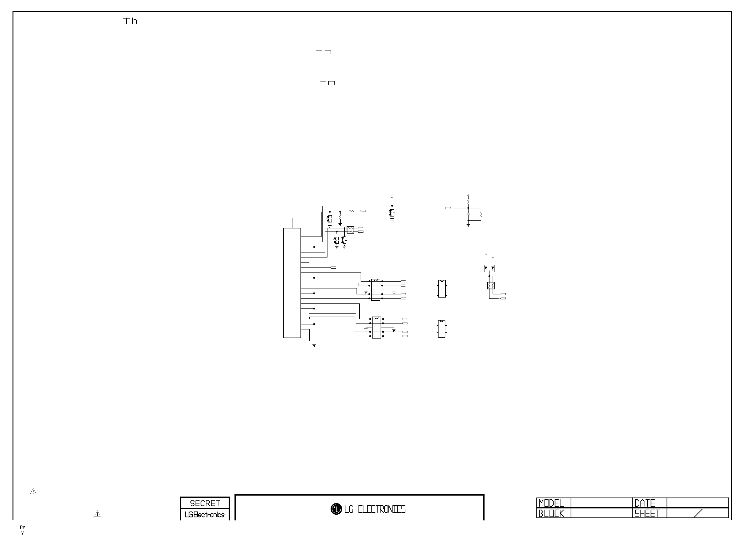
This Ciruit is used as HDMI Input2 of LB87 Series over(HDMI 4ea)
Copyright ⓒ 2015 LG Electronics. Inc. All right reserved.
Only for training and service purposes
LGE Internal Use Only
BODY_SHIELD
20
EAG63530101
JK3301
DAADR019A
19
18
17
16
15
14
13
12
11
10
9
8
7
6
5
4
3
2
1
HP_DET
5V
GND
DDC_DATA
DDC_CLK
ARC
CE_REMOTE
CK-
CK_GND
CK+
D0-
D0_GND
D0+
D1-
D1_GND
D1+
D2-
D2_GND
D2+
ESD_HDMI
VA3302
ESD_HDMI
R3302
100K
R3301
VA3301
CEC_REMOTE
AR3301
33
1/16W
VA3303
ESD_HDMI
33
HDMI_HPD_3
DDC_SCL_3
DDC_SDA_3
D3301
RCLAMP0524PA
1
10
2
9
8
3
7
4
6
5
ESD_HDMI_TMDS
D3302
RCLAMP0524PA
1
2
3
4
5
ESD_HDMI_TMDS
5V_HDMI_3
CK-_HDMI3
CK+_HDMI3
D0-_HDMI3
D0+_HDMI3
D1-_HDMI3
D1+_HDMI3
D2-_HDMI3
D2+_HDMI3
5V_HDMI_3_SOC
D3301-*1
IP4294CZ10-TBR
@volta
1
2
3
4
5
ESD_HDMI_TVS
D3302-*1
IP4294CZ10-TBR
@volta
1
2
3
4
5
ESD_HDMI_TVS
VA3304
ESD_HDMI
10
9
8
7
6
5V_HDMI_3
R3303
10
C3301
R3304
1uF
5.1K
10V
+5V_NORMAL
5V_HDMI_3
AR3302
47K
1/16W
A2CA1
DDC_SDA_3
DDC_SCL_3
D3303
10
9
8
7
6
10
9
8
7
6
THE SYMBOL MARK OF THIS SCHEMETIC DIAGRAM INCORPORATES
SPECIAL FEATURES IMPORTANT FOR PROTECTION FROM X-RADIATION.
FIRE AND ELECTRICAL SHOCK HAZARDS, WHEN SERVICING IF IS
ESSENTIAL THAT ONLY MANUFACTURES SPECIFIED PARTS BE USED FOR
THE CRITICAL COMPONENTS IN THE SYMBOL MARK OF THE SCHEMETIC.
MID_LG1311
HDMI4
2013.07.25
33
Page 41
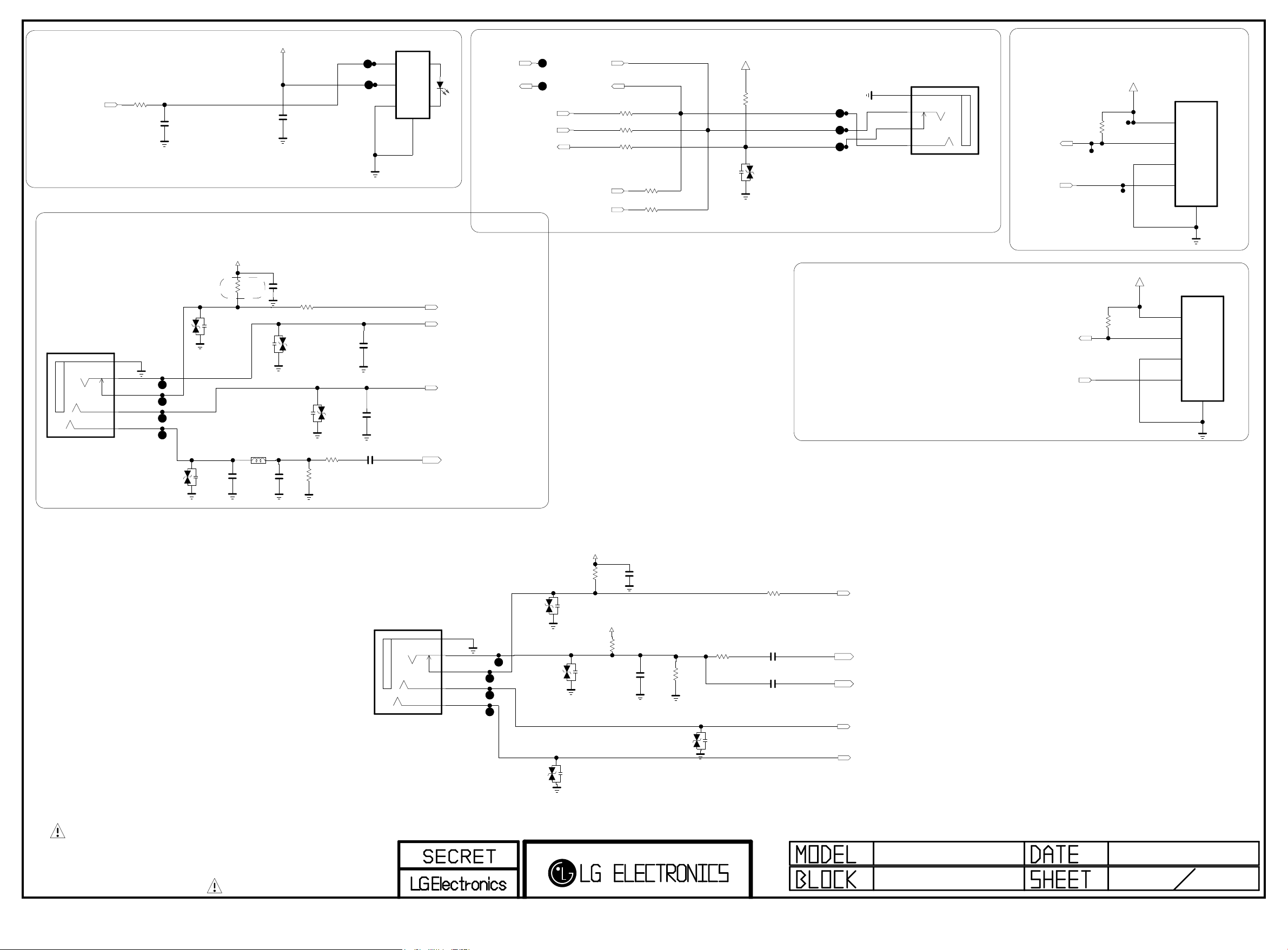
SPDIF OUT
Copyright ⓒ 2015 LG Electronics. Inc. All right reserved.
Only for training and service purposes
LGE Internal Use Only
SPDIF_OUT
CVBS 1 PHONE JACK
R3601
33
C3601
47pF
50V
+3.3V_NORMAL
C3604
0.1uF
16V
VIN
VCC
GND
JK3603
JSTIB15
A
B
C
Fiber Optic
4
SHIELD
RIN1
DOUT1
HP_ROUT
HP_LOUT
HP_DET
HP OUT
TP3601
TP3602
RIN1
DOUT1
IRB_DATA
IRB_3.3V
HP_OUT
HP_OUT
HP_OUT
R3608
150
R3609
150
R3610
100
IR_Bla
R3611
0
IR_Bla
R3612
0
+3.3V_NORMAL
R3613
10K
HP_OUT
VA3609
5.6V
HP_OUT
JK3604
PEJ038-3B6
5GND
4L
3DETECT
1R
EAG61030009
HP/RS232
UART FOR DEBUG
+3.5V_ST
R3614
10K
SOC_RX
SOC_TX
P3601
12507WS-04L
1
2
3
4
5
JK3601
PEJ038-4Y6
5 M5_GND
4 M4
3 M3_DETECT
1 M1
6 M6
+3.3V_NORMAL
VA3602
5.6V
VA3605
5.5V
R3602
330K
C3600
150pF
L3601
1uH
C3608
18pF
50V
C3602
150pF
R3618
1K
1/16W
5%
VA3601
5.6V
VA3603
5.6V
R3605 100
3216
R3604
75
EMS_EU/AJ/KR
C3610
1000pF
EMS_EU/AJ/KR
C3611
1000pF
C3605
0.047uF
JK3602
PEJ038-4G6
AV1_CVBS_DET
COMP1/AV1/DVI_L_IN
COMP1/AV1/DVI_R_IN
AV1_CVBS_IN_SOC
COMPONENT 1 PHONE JACK
5 M5_GND
4 M4
3 M3_DETECT
1 M1
6 M6
+3.3V_NORMAL
VA3610
5.6V
VA3604
5.6V
R3616
10K
+3.3V_NORMAL
R3603
10K
C3609
18pF
50V
C3603
150pF
OPT
3216
R3606
75
R3607 33
R3617
1K
1/16W
5%
C3606 0.047uF
C3607 1000pF
DDTS TEST ONLY
COMP1_DET
COMP2_Y_IN_SOC
COMP2_Y_IN_SOC_SOY
M_REMOTE_RX
M_REMOTE_TX
+3.5V_ST
OPT
R3615
10K
OPT
P3602
12507WS-04L
1
2
3
4
5
THE SYMBOL MARK OF THIS SCHEMETIC DIAGRAM INCORPORATES
SPECIAL FEATURES IMPORTANT FOR PROTECTION FROM X-RADIATION.
FIRE AND ELECTRICAL SHOCK HAZARDS, WHEN SERVICING IF IS
ESSENTIAL THAT ONLY MANUFACTURES SPECIFIED PARTS BE USED FOR
THE CRITICAL COMPONENTS IN THE SYMBOL MARK OF THE SCHEMETIC.
VA3608
5.5V
VA3607
5.5V
COMP1_Pb
COMP1_Pr
MID_LG1311
Jack_Vertical_Common
2013.04.03
11
31
Page 42
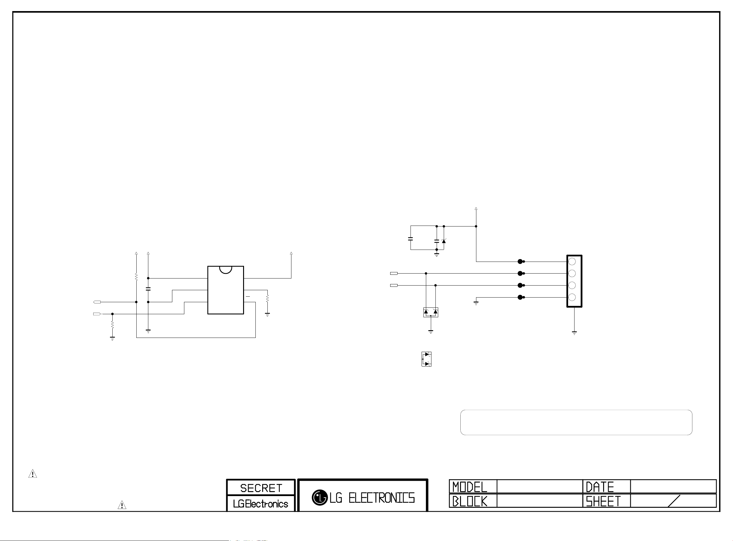
+5V_USB_1
Copyright ⓒ 2015 LG Electronics. Inc. All right reserved.
Only for training and service purposes
LGE Internal Use Only
PAGE 14
value change
10K(2.63V) --> 4.7K(2.97V)
/USB_OCD1
USB_CTL1
R4500
10K
+3.3V_NORMAL
R4501
4.7K
+5V_NORMAL
0.1uF
16V
OCP USB1
VIN
1
GND
2
EN
3
IC4500
BD2242G
USB1 (2.0)
MAX 1.5A
OPT
C4501
C4502
10uF
22uF
10V
+5V_USB_1
VOUT
6
ILIM
5
1%
OC
4
14K
R4502
USB_DM1
USB_DP1C4500
10V
D4500
RCLAMP0582B
USB_ESD_0582B
USB_ESD_0502BA
D4500-*1
RCLAMP0502BA
5V
D4501
USB_ESD_SD05
3AU04S-305- ZC- (LG)
JK4500
1234
USB DOWN ST REA M
5
THE SYMBOL MARK OF THIS SCHEMETIC DIAGRAM INCORPORATES
SPECIAL FEATURES IMPORTANT FOR PROTECTION FROM X-RADIATION.
FIRE AND ELECTRICAL SHOCK HAZARDS, WHEN SERVICING IF IS
ESSENTIAL THAT ONLY MANUFACTURES SPECIFIED PARTS BE USED FOR
THE CRITICAL COMPONENTS IN THE SYMBOL MARK OF THE SCHEMETIC.
EAX6536390* : Use RClamp0582B, SD05
EAX6538400* : Use RClamp0502BA
MID_LG1311
USB 1(DVR)
2013.04.03
1
Page 43
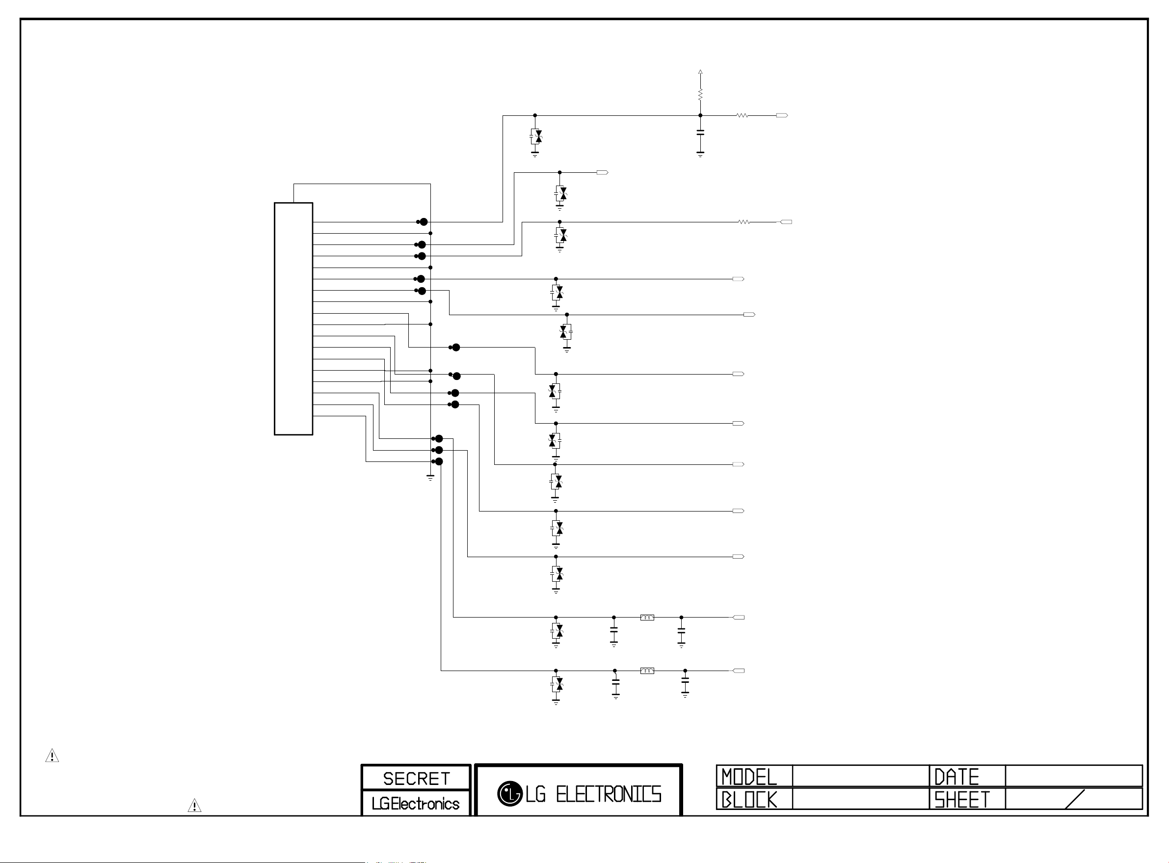
VA4601
Copyright ⓒ 2015 LG Electronics. Inc. All right reserved.
Only for training and service purposes
LGE Internal Use Only
5.6V
+3.3V_NORMAL
PAGE 15
EU
R4601
CLOSE TO JUNCTION
10K
EU
EU
C4604
0.1uF
EU
R4602
100
SC_DET
Full Scart
SHIELD
19
AV_DET
18
COM_GND
17
SYNC_IN
16
SYNC_OUT
15
SYNC_GND
14
RGB_IO
13
R_OUT
12
R_GND
11
G_OUT
10
G_GND
9
ID
8
B_OUT
7
AUDIO_L_IN
6
B_GND
5
AUDIO_GND
4
AUDIO_L_OUT
3
AUDIO_R_IN
2
AUDIO_R_OUT
1
DA1R018H91E
JK4600
EU
VA4609
5.5V
EU
VA4610
5.5V
EU
VA4602
5.6V
VA4604
5.5V
VA4605
5.5V
VA4600
20V
EU
VA4603
5.5V
EU
EU
EU
EU
SC_CVBS_IN
1/16W
R8904
EU
75
SC_FB
SC_G
SC_B
SC_ID
DTV/MNT_V_OUT
SC_R
THE SYMBOL MARK OF THIS SCHEMETIC DIAGRAM INCORPORATES
SPECIAL FEATURES IMPORTANT FOR PROTECTION FROM X-RADIATION.
FIRE AND ELECTRICAL SHOCK HAZARDS, WHEN SERVICING IF IS
ESSENTIAL THAT ONLY MANUFACTURES SPECIFIED PARTS BE USED FOR
THE CRITICAL COMPONENTS IN THE SYMBOL MARK OF THE SCHEMETIC.
VA4606
5.6V
EU
VA4607
5.6V
EU
VA4608
5.6V
EU
VA4611
5.6V
SC_L_IN
EU
SC_R_IN
BLM18PG121SN1D
C4600
1000pF
50V
BLM18PG121SN1D
C4601
1000pF
50V
L4600
EU
EU
L4601
EU
EU
EU
C4602
4700pF
C4603
4700pF
EU
DTV/MNT_L_OUT
DTV/MNT_R_OUT
Page 44
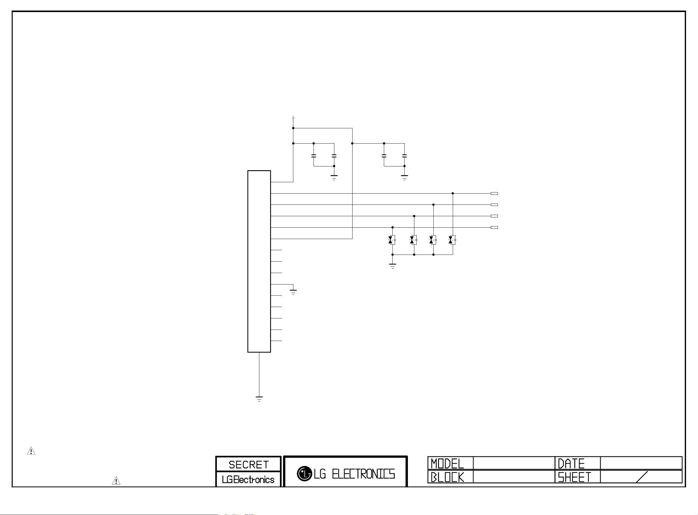
Ethernet Block
Copyright ⓒ 2015 LG Electronics. Inc. All right reserved.
Only for training and service purposes
LGE Internal Use Only
LAN_JACK_POWER
PAGE 16
JK5100
BS-R570098
12
SHIELD
1
2
3
4
5
6
7
8
9
10
11
D1
D2
D3
D4
R1
R2
R3
R4
R5
R6
R7
R8
R9
R10[GND]
R11
YL_C
YL_A
GN_C
GN_A
C5100
0.1uF
16V
C5101
0.01uF
50V
VA5100
5.5V
ESD_LAN
C5102
0.1uF
16V
VA5101
5.5V
ESD_LAN
C5103
0.01uF
50V
VA5102
5.5V
ESD_LAN
VA5103
5.5V
ESD_LAN
EPHY_TDP
EPHY_TDN
EPHY_RDP
EPHY_RDN
THE SYMBOL MARK OF THIS SCHEMETIC DIAGRAM INCORPORATES
SPECIAL FEATURES IMPORTANT FOR PROTECTION FROM X-RADIATION.
FIRE AND ELECTRICAL SHOCK HAZARDS, WHEN SERVICING IF IS
ESSENTIAL THAT ONLY MANUFACTURES SPECIFIED PARTS BE USED FOR
THE CRITICAL COMPONENTS IN THE SYMBOL MARK OF THE SCHEMETIC.
Page 45
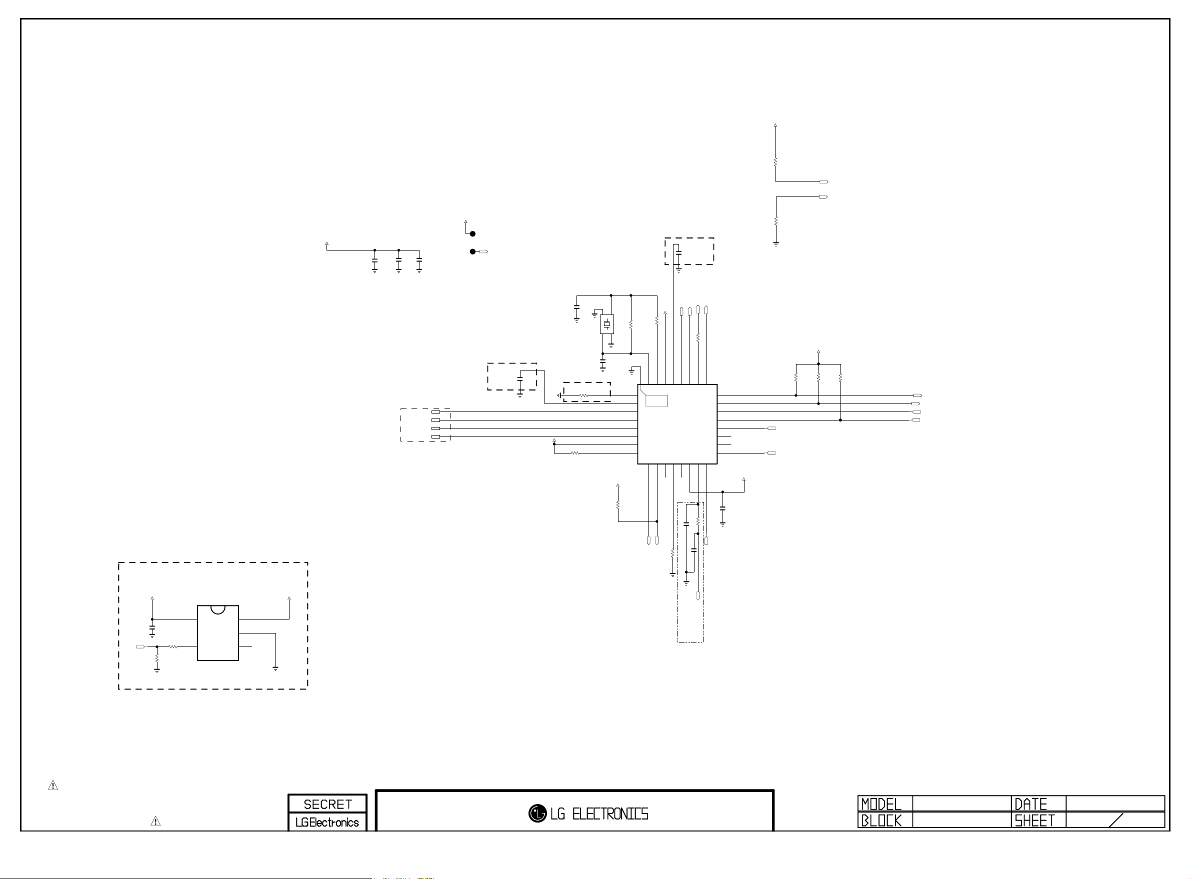
Ethernet Block
Copyright ⓒ 2015 LG Electronics. Inc. All right reserved.
Only for training and service purposes
LGE Internal Use Only
PAGE 17
+3.5V_WOL
3.3K
WOL POWER ENABLE CONTROL
+3.5V_WOL
LAN_JACK_POWER
C5203
C5201
C5200
4.7uF
10V
Place 0.1uF close to each power pins
0.1uF
0.1uF
16V
16V
EPHY_RDP
EPHY_RDN
EPHY_TDP
EPHY_TDN
ETHERNET INTERFACE
- CROSS CONNECTION
(PATTERN ISSUE)
ET_COL/SNI
Place this cap. near IC
C5205
Place this Res. near IC
0.1uF
16V
Route Single 50 Ohm, Differential 100 Ohm
+3.5V_WOL
R5203
3.3K
C5206
8pF
50V
R5204
2.49K 1%
1
4
3
XTA L_2
C5207
8pF
50V
AVDD10OUT
+3.5V_WOL
XTA L_12GND _1
X52 00
25M Hz
GND _2
RSET
MDI+[0]
MDI-[0]
MDI+[1]
MDI-[1]
AVDD33_1
RXDV
3.3K
R5200
+3.5V_WOL
R52021M
OPT
[EP]
CKXTAL2
1
THERMAL
2
3
4
5
6
7
8
RXD[0]10RXD[1]
Place this cap. near IC
C5208
0.1uF
16V
ET_RXER
R5218
0
DVDD10OUT
AVDD33_2
CKXTAL1
29
30
31
32
33
IC5200
RTL8201F-VB-CG
9
11
12
13
RXC
RXD[2]/INTB
RXD[3]/CLK_CTL
C5209
33pF
3.3K
R5208
EPHY_RXD1
EPHY_RXD0
EPHY_CRS_DV
ET_COL/SNI
CRS/CRS_DV
COL28RXER/FXEN
26
27
14
15
TXC
DVDD33
R5209
C5202
Place near IC
5pF
EPHY_ACTIVITY
R521033
LED1/PHYAD[1]
25
LED0/PHYAD[0]/PMEB
24
MDIO
23
MDC
22
PHYRSTB
21
TXEN
20
TXD[3]
19
TXD[2]
18
TXD[1]
17
16
TXD[0]
51
EPHY_TXD0
+3.5V_WOL
C5211
0.1uF
16V
R5215
3.3K
R5217
EPHY_EN
EPHY_TXD1
R5205
+3.5V_WOL
3.3K
R5212
1.5K
1/16W
EPHY_ACTIVITY
ET_RXER
1%
R5219
10K
1/16W
5%
WOL/ETH_POWER_ON
EPHY_MDIO
EPHY_MDC
/RST_PHY
(from SOC)
+3.5V_ST
R5222
10K
IN
EN
WOL_CTL
C5204
0.1uF
R5223 33
OPT
THE SYMBOL MARK OF THIS SCHEMETIC DIAGRAM INCORPORATES
SPECIAL FEATURES IMPORTANT FOR PROTECTION FROM X-RADIATION.
FIRE AND ELECTRICAL SHOCK HAZARDS, WHEN SERVICING IF IS
ESSENTIAL THAT ONLY MANUFACTURES SPECIFIED PARTS BE USED FOR
THE CRITICAL COMPONENTS IN THE SYMBOL MARK OF THE SCHEMETIC.
IC5201
AP2191WG-7
5
4
+3.5V_WOL
OUT
1
GND
2
FLG
3
EPHY_REFCLK
BSD-NC4_H052-HD
2012-09-12
ETHERNET
Page 46
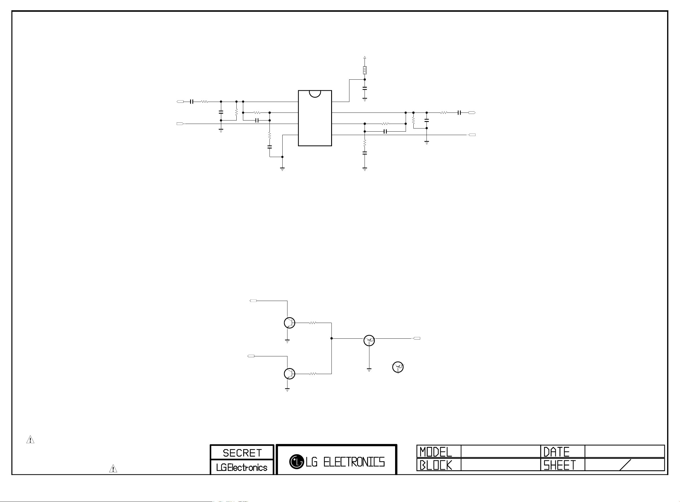
AUD_OUT >> EU/CHINA_HOTEL_OPT
Copyright ⓒ 2015 LG Electronics. Inc. All right reserved.
Only for training and service purposes
LGE Internal Use Only
EU
DTV/MNT_L_OUT
C6000
1uF
25V
SCART_LOUT
EU
R6000
2.2K
OPT
C6002
6800pF
OPT
R6002
470K
EU
R6004 33K
C6003 33pF
EU
R6001
10K
C6001
4.7uF
10V
PAGE 19
+12V
EU
SIGN6000001
EU
EU
L6000
EU
C6004
0.1uF
50V
R6008 33K
C6005
10K
R6003
4.7uF
10V
C6006
EU
R6011
2.2K
EU
33pF
EU
OPT
R6010
470K
OPT
C6007
6800pF
EU
C6008
1uF
25V
DTV/MNT_R_OUT
SCART_ROUT
IC6000
AZ4580MTR-E1
OUT1
1
IN1-
2
IN1+
EU
VEE
EU
EU
3
4
VCC
8
OUT2
7
IN2-
6
IN2+
5
[SCART AUDIO MUTE]
DTV/MNT_L_OUT
C
Q6000
MMBT3904(NXP)
B
EU
E
DTV/MNT_R_OUT
C
Q6001
MMBT3904(NXP)
B
EU
E
THE SYMBOL MARK OF THIS SCHEMETIC DIAGRAM INCORPORATES
SPECIAL FEATURES IMPORTANT FOR PROTECTION FROM X-RADIATION.
FIRE AND ELECTRICAL SHOCK HAZARDS, WHEN SERVICING IF IS
ESSENTIAL THAT ONLY MANUFACTURES SPECIFIED PARTS BE USED FOR
THE CRITICAL COMPONENTS IN THE SYMBOL MARK OF THE SCHEMETIC.
R6013
R6014
EU
1K
EU
1K
EU_SCART_MUTE_ISAHAYA
Q6002
RT1P141C-T112
E
C
B
EU_SCART_MUTE_NXP
SCART_MUTE
PDTA114ET
Q6002-*1
E
C
B
MID_MAIN
SCART AMP
2013.03.19
3
25
Page 47
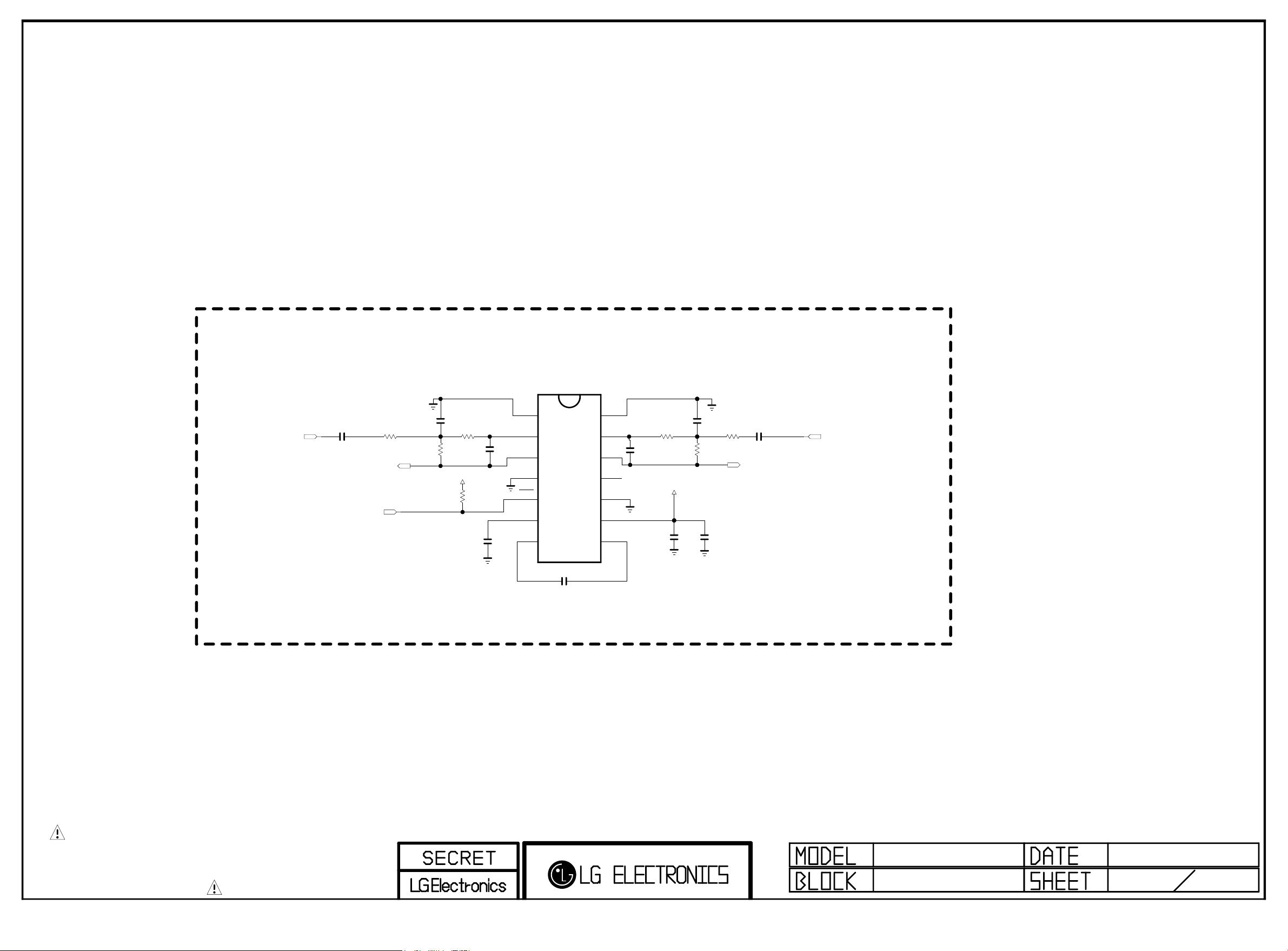
EARPHONE AMP
Copyright ⓒ 2015 LG Electronics. Inc. All right reserved.
Only for training and service purposes
LGE Internal Use Only
IC6100
TPA6138A2
HP_OUT
R6100
10K
C6104
18pF
R6103
HP_OUT
+3.3V_NORMAL
1%
43K
4.7K
R6105
HP_OUT
HP_OUT
R6106
43K
1%
HP_OUT
HP_OUT
HP_OUT
C6100
1uF
10V
HP_ROUT_MAIN HP_LOUT_MAIN
HP_OUT
HP_ROUT_AMP
SIDE_HP_MUTE
C6108
10pF
50V
C6102
1uF
10V
+INR
-INR
OUTR
GND_1
MUTE
VSS
1
HP_OUT
2
3
4
5
6
CN
7
HP_OUT
C6103
1uF
10V
+INL
14
-INL
13
OUTL
12
UVP
11
GND_2
10
VDD
9
CP
8
HP_OUT
C6106
10pF
50V
HP_OUT
HP_OUT
R6104
43K
1%
HP_OUT
C6109
18pF
1%
R6102
43K
HP_OUT
+3.3V_NORMAL
HP_OUT
C6105
1uF
16V
10V
C6107
0.1uF
HP_OUT
R6101
10K
C6101
1uF
10V
HP_OUT
HP_LOUT_AMP
PAGE 20
THE SYMBOL MARK OF THIS SCHEMETIC DIAGRAM INCORPORATES
SPECIAL FEATURES IMPORTANT FOR PROTECTION FROM X-RADIATION.
FIRE AND ELECTRICAL SHOCK HAZARDS, WHEN SERVICING IF IS
ESSENTIAL THAT ONLY MANUFACTURES SPECIFIED PARTS BE USED FOR
THE CRITICAL COMPONENTS IN THE SYMBOL MARK OF THE SCHEMETIC.
HEADPHONE AMP
2011.09.29
61
Page 48
PAGE 21
Copyright ⓒ 2015 LG Electronics. Inc. All right reserved.
Only for training and service purposes
LGE Internal Use Only
CI POWER ENABLE CONTROL
+5V_NORMAL
PCM_5V_CTL
C6211
0.1uF
50V
R6218
10K
CI
CI
R6217
100
IN
EN
IC6200
AP2151WG-7
5
4
+5V_CI_ON
OUT
1
CI
GND
2
FLG
3
C6210
1uF
25V
CI
R6219
10K
CI
THE SYMBOL MARK OF THIS SCHEMETIC DIAGRAM INCORPORATES
SPECIAL FEATURES IMPORTANT FOR PROTECTION FROM X-RADIATION.
FIRE AND ELECTRICAL SHOCK HAZARDS, WHEN SERVICING IF IS
ESSENTIAL THAT ONLY MANUFACTURES SPECIFIED PARTS BE USED FOR
THE CRITICAL COMPONENTS IN THE SYMBOL MARK OF THE SCHEMETIC.
Page 49
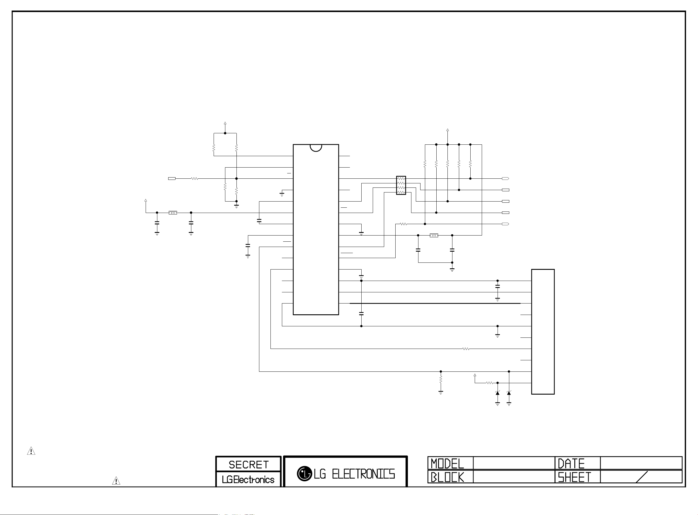
SMARTCARD_PWR_SEL/SD_EMMC_DATA[1]
Copyright ⓒ 2015 LG Electronics. Inc. All right reserved.
Only for training and service purposes
LGE Internal Use Only
+5V_NORMAL
JAPAN
C6300
0.1uF
16V
B-CAS (SMART CARD) INTERFACE
R6300 22
JAPAN
L6300
BLM18PG121SN1D
CLKDIV1 CLKDIV2 : F_CRD_CLK
---------------------------- 1 0 CLKIN
+3.3V_NORMAL
2.7K
JAPAN
R6301
JAPAN
JAPAN
JAPAN
C6301
10uF
10V
R6304
2.7K
R6305
R6306
JAPAN
C6302
0.1uF
OPT
16V
2.7K
JAPAN
JAPAN
C6303
0.1uF
16V
CLKDIV1
CLKDIV2
5V/3V
PGND
VDDP
VUP
PRES
PRES
I/O
AUX2
AUX1
CGND
S2
S1
IC6300
TDA8024TT
1
2
3
4
5
6
7
8
9
10
11
12
13
14
JAPAN
PAGE 22
INT CMDVCC : STATUS
+3.3V_NORMAL
AUX2UC
28
AUX1UC
27
I/OUC
26
XTAL2
25
XTAL1
24
OFF
23
GND
22
VDD
21
RSTIN
20
CMDVCC
19
PORADJ
18
VCC
17
RST
16
CLK
15
JAPAN
C6304
0.1uF
16V
JAPAN
AR6300
33
JAPAN
R6311
Place CLK C3 far from C2,C7,C4 and C8
1.2K
JAPAN
R6317
22
BLM18PG121SN1D
JAPAN
C6305
0.1uF
16V
75 ohm in I/O is for short circuit Protection
1.2K
OPT
R6318
JAPAN
L6301
JAPAN
1.2K
JAPAN
R6315
10K
R6312
OPT
JAPAN
C6306
0.1uF
16V
1.2K
1.2K
JAPAN
R6316
R6319
JAPAN
R6313
75
+3.3V_NORMAL
R6314
JAPAN
ZD6300
JAPAN
1K
5V
JAPAN
SMARTCARD_DATA/SD_EMMC_CLK
SMARTCARD_CLK/SD_EMMC_DATA[0]
SMARTCARD_DET/SD_EMMC_DATA[3]
SMARTCARD_RST/SD_EMMC_DATA[2]
SMARTCARD_VCC/SD_EMMC_CMD
B-CAS SLOT
VCC
RST
CLK
GND
VPP
I/O
SW1
SW2
C1
C2
C3
C4
C5
C6
C7
C8
S1
S2
P6300
JAPAN
10057542-1311FLF(B CAS Slot)
C6307
0.33uF
16V
RESERVED_1
RESERVED
ZD6301
5V
JAPAN
-------------------------------- HIGH HIGH CARD PRESENT
LOW HIGH CARD not PRESENT
THE SYMBOL MARK OF THIS SCHEMETIC DIAGRAM INCORPORATES
SPECIAL FEATURES IMPORTANT FOR PROTECTION FROM X-RADIATION.
FIRE AND ELECTRICAL SHOCK HAZARDS, WHEN SERVICING IF IS
ESSENTIAL THAT ONLY MANUFACTURES SPECIFIED PARTS BE USED FOR
THE CRITICAL COMPONENTS IN THE SYMBOL MARK OF THE SCHEMETIC.
MID_LG1311
B-CAS I/F
2013.04.03
Page 50
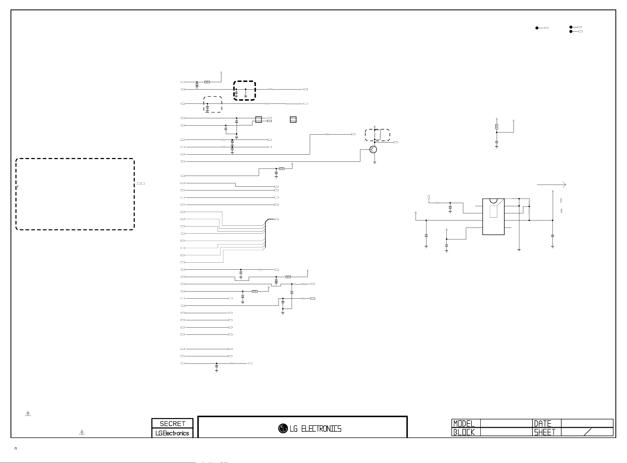
Global F/E Option Name
Copyright ⓒ 2015 LG Electronics. Inc. All right reserved.
Only for training and service purposes
LGE Internal Use Only
1. TU
2. Tuner Name = TDJ’H’,TDj’M’...
3. Country Name = KR,US,BR,EU ...
Example of Option name
TU_ALL_IntDemod = All Tuner type for Internal demod
TU_M/W = apply TDSM&TDSW Type Tuner
14’ Tuner Type for Global
TDJ’H’-G101D : Half NIM for EU,AJJA
TDJ’H’-H101F : Half NIM for US, KR
TDJ’K’-T101F : Half NIM for TW
TDJ’M’-C301D,F : FULL NIM for China
TDJ’M’-B101F : Brazil NIM with Isolater Type
TDJ’M’-K101F : colombia NIM
TDJ’M’-G101D,G105D,G151D : EU Combo&Full NIM
TDJ’M’-H101F,H151F : Korea PIP tuner
TDJ’W’-A151D : AJJA T2 PIP
1
2
3
4
5
6
7
8
9
10
11
12
14
15
16
17
18
19
20
21
22
23
24
25
26
27
28
29
30
31
34
36
37
38
39
40
45
+3.3V_LNA_TU
RF_SWITCH_CTL_TU
IF_AGC_TU
I2C_SCL6_TU
I2C_SDA6_TU
IF_P_TU
IF_N_TU
TU_SIF_TU
TU_CVBS_TU
+3.3V_TU
FE_DEMOD1_TS_ERROR
FE_DEMOD1_TS_CLK
FE_DEMOD1_TS_SYNC
FE_DEMOD1_TS_VAL
FE_DEMOD1_TS_DATA[0]
FE_DEMOD1_TS_DATA[1]
FE_DEMOD1_TS_DATA[2]
FE_DEMOD1_TS_DATA[3]
FE_DEMOD1_TS_DATA[4]
FE_DEMOD1_TS_DATA[5]
FE_DEMOD1_TS_DATA[6]
FE_DEMOD1_TS_DATA[7]
/TU_RESET1_TU
+3.3V_DEMOD_TU
I2C_SCL4_TU
D_Demod_Core
LNB_TX
I2C_SDA4_TU
LNB_OUT
FE_DEMOD2_TS_ERROR
FE_DEMOD2_TS_SYNC
FE_DEMOD2_TS_CLK
FE_DEMOD2_TS_VAL
FE_DEMOD2_TS_DATA
/TU_RESET2_TU
close to Tuner
L6500
BLM18PG121SN1D
C6501
0.1uF
TU_ALL_IntDemod
C6502
0.1uF
16V
TU_ALL_IntDemod
TU_ALL_IntDemod
+3.3V_TUNER
close to Tuner
R6504
10
R6505
10
TU_W
C6509
16V
0.1uF
close to TUNER
TU_K/M/W_TW/BR/CO/CN
TU_K/M/W_TW/BR/CO/CN
R6503
C6504
10K
0.1uF
TU_ALL_IntDemod
AR6500
33
C6505
47pF
50V
OPT
C6503
47pF
50V
OPT
C6519
33pF
TU_H/M_EU/BR/TW/CO
C6520
33pF
TU_H/M_EU/BR/TW/CO
1/16W
TU_ALL
should be guarded by ground,Match GND VIA
close to Tuner
FE_DEMOD1_TS_DATA[0]
FE_DEMOD1_TS_DATA[1]
FE_DEMOD1_TS_DATA[2]
FE_DEMOD1_TS_DATA[3]
FE_DEMOD1_TS_DATA[4]
FE_DEMOD1_TS_DATA[5]
FE_DEMOD1_TS_DATA[6]
FE_DEMOD1_TS_DATA[7]
TU_M/W
16V
0.1uF
TU_M/W
L6505
BLM18PG121SN1D
TU_M/W
C6506
0.1uF
/TU_RESET2
R6501
100
TU_M/W
C6507
LNB_TX
LNB_OUT
FE_DEMOD2_TS_ERROR
FE_DEMOD2_TS_SYNC
FE_DEMOD2_TS_CLK
FE_DEMOD2_TS_VAL
FE_DEMOD2_TS_DATA
R6502
100
TU_W
R6507
TU_K/M/W_TW/BR/CO/CN
R6506
1K
I2C_SCL6
I2C_SDA6
TU_M_KR/EU // W_ALL
TU_M_KR/EU // W_ALL
Demod_Core
1K
IF_P
IF_N
BLM18PG121SN1D
/TU_RESET1
AR6500-*1
200
1/16W
TU_W_BR/TW
L6501
C6510
0.1uF
FE_DEMOD1_TS_ERROR
FE_DEMOD1_TS_CLK
FE_DEMOD1_TS_SYNC
FE_DEMOD1_TS_VAL
FE_DEMOD1_TS_DATA[0-7]
BLM18PG121SN1D
C6511
0.1uF
OPT
TU_M/W
L6503
TU_M/W
C6512
18pF
50V
+3.3V_TUNER
+3.3V_TUNER
R6510 33
TU_M/W
OPT
C6513
18pF
50V
R6509 33
TU_M/W
1. should be guarded by ground
2. No via on both of them
3. Signal Width >= 12mils
Signal to Signal Width = 12mils
RF_SWITCH_CTL
Ground Width >= 24mils
IF_AGC
TU_ALL_2178B
R6513 0
I2C_SCL4
I2C_SDA4
TUNER_SIF
+3.3V_TUNER
TU_ALL_2178B
R6516
200
B
TU_ALL_2178B
R6517
200
E
TU_ALL_2178B
Q6502
MMBT3906(NXP)
C
1608 perallel
because of derating
TU_CVBS
+3.5V_ST
POWER_ON/OFF2_1
TU_M/W
10K
R6500
TU_M/W
C6500
10uF
10V
+5V_NORMAL
TU_M/W
C6515
1uF
10V
+3.3V_NORMAL
C6517
22uF
10V
85C
IC6500
TU_M/W
C6516
0.1uF
AP2132MP-2.5TRG1
PG
1
EN
2
VIN
3
VCTRL
4
Vout=0.6*(1+R1/R2)
L6504
BLM18PG121SN1D
TU_M/W
9
THERMAL
2A
/TU_RESET2_TU
+3.3V_TUNER
T2 : Max 1.7A
else : Max 0.7A
Demod_Core
[EP]
R6521-*1
TU_M/W
C6518
10uF
10V
18K
R6519-*1
16K
TU_M/W_1.1V
TU_M/W_1.1V
TU_M/W_1.2V
GND
8
ADJ
7
VOUT
6
NC
5
10K
R65 21
R65 19
10. 5K
TU_M/W_1.2V
R2
R1
/TU_RESET2
FE_DEMOD1_TS_ERROR
THE SYMBOL MARK OF THIS SCHEMETIC DIAGRAM INCORPORATES
SPECIAL FEATURES IMPORTANT FOR PROTECTION FROM X-RADIATION.
FIRE AND ELECTRICAL SHOCK HAZARDS, WHEN SERVICING IF IS
ESSENTIAL THAT ONLY MANUFACTURES SPECIFIED PARTS BE USED FOR
THE CRITICAL COMPONENTS IN THE SYMBOL MARK OF THE SCHEMETIC.
TUNER
2012.07.10
65
Page 51
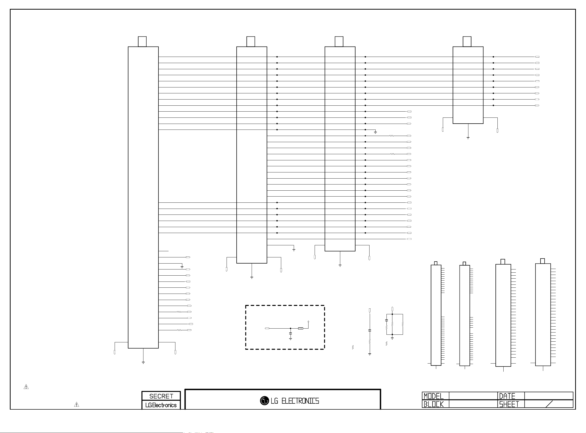
TU_TDJW-B251F
Copyright ⓒ 2015 LG Electronics. Inc. All right reserved.
Only for training and service purposes
LGE Internal Use Only
TU6700
TDJW-B251F
DVB_TDJM_G251D
TU6707
TDJM-G251D
ATSC_TDJM_H151F
TU6701
TDJM-H151F
ATSC_TDJH_H251F
TU6703
TDJH-H251F
TU_GND_A
B1[+3.3V]
1
RF_S/W_CTL
2
NC_1
3
SCL_RF
4
SDA_RF
5
NC_2
6
NC_3
7
M_SIF
8
M_CVBS
9
NC_4
10
B2[+3.3V]
11
NC_5
12
GND_1
13
M_RESET_DEMOD
25
B3[+3.3V]
26
SCL_DEMOD
27
B4[+1.1V]
28
NC_6
29
SDA_DEMOD
30
NC_7
33
M_ERROR
34
GND_2
35
M_SYNC
36
M_MCLK
37
NC_8
38
M_VALID
39
M_DATA
40
S_ERROR
41
S_SYNC
42
S_MCLK
43
S_VALID
44
S_RESET_DEMOD
45
S_DATA
46
A1
A1
B1
B1
TU_W
R6804
0
TU_W
R6805
0
FE_DEMOD2_TS_ERROR
FE_DEMOD2_TS_SYNC
FE_DEMOD2_TS_CLK
+2.5V_DEMOD
FE_DEMOD2_TS_VAL
FE_DEMOD2_TS_DATA
FE_DEMOD1_TS_ERROR
FE_DEMOD1_TS_SYNC
FE_DEMOD1_TS_CLK
FE_DEMOD1_TS_VAL
/TU_RESET2_TU
FE_DEMOD1_TS_DATA[0]
A1
TU_GND_A
A1
47
SHIELD
+2.5V_DEMOD
47
SHIELD
TU_GND_B
B1[+3.3V]
1
NC_1
2
NC_2
3
SCL_RF
4
SDA_RF
5
NC_3
6
NC_4
7
SIF
8
CVBS
9
NC_5
10
B2[+3.3V]
11
ERROR
12
GND_1
13
MCLK
14
SYNC
15
VAILD
16
D0
17
D1
18
D2
19
D3
20
D4
21
D5
22
D6
23
D7
24
RESET_DEMOD
25
B3[+3.3V]
26
SCL_DEMOD
27
B4[+1.1V]
28
F22_OUTPUT
29
SDA_DEMOD
30
LNB
31
GND_2
32
B1
B1
TU_GND_B
+2.5V_NORMAL
L6502
BLM18PG121SN1D
C6508
0.1uF
A1
TU_GND_A
B1[+3.3V]
1
NC_1
2
M_DIF_AGC
3
SCL_RF
4
SDA_RF
5
M_DIF[P]
6
M_DIF[N]
7
S_SIF
8
S_CVBS
9
NC_2
10
B2[+3.3V]
11
S_ERROR
12
GND_1
13
S_MCLK
14
S_SYNC
15
S_VAILD
16
S_DATA
17
NC_3
18
NC_4
19
NC_5
20
NC_6
21
NC_7
22
NC_8
23
NC_9
24
S_RESET_DEMOD
25
B3[+3.3V]
26
SCL_DEMOD
27
B4[+1.1V]
28
NC_10
29
SDA_DEMOD
30
B1
A1
B1
TU_M
0
TU_M
R6802
R6803
0
+3.3V_TU
+3.3V_TU
FE_DEMOD1_TS_ERROR
FE_DEMOD1_TS_CLK
FE_DEMOD1_TS_SYNC
FE_DEMOD1_TS_VAL
FE_DEMOD1_TS_DATA[0]
FE_DEMOD1_TS_DATA[1]
FE_DEMOD1_TS_DATA[2]
FE_DEMOD1_TS_DATA[3]
FE_DEMOD1_TS_DATA[4]
FE_DEMOD1_TS_DATA[5]
FE_DEMOD1_TS_DATA[6]
FE_DEMOD1_TS_DATA[7]
/TU_RESET1_TU
+3.3V_DEMOD_TU
I2C_SCL4_TU
D_Demod_Core
LNB_TX
I2C_SDA4_TU
LNB_OUT
A1
TU_GND_A
A1
47
SHIELD
47
SHIELD
R6702-*1
0
TU_M_CN
DVB-T GND
TU_GND_B
TU_GND_B
C6701
630V
1000pF
TU_M_EU/AJ/KR/US/CN
R6702
10
TU_M_EU/AJ/KR/US
TU_GND_A
C6801
630V
1000pF
TU_M/W_EU/AJ/TW/BR/CN
0
R6700
R6801
0
TU_M_KR/US
TU_M/W_TW/BR/CN
R6801-*1
22
TU_M_EU/AJ
R6701 0
TU_M_KR/US
JAPAN_TUNER
A1A1B1
47
SHIELD
TU6700-*2
TDJW-J251F
B1[+3.3V]
1
NC_1
2
NC_2
3
SCL_RF
4
SDA_RF
5
NC_3
6
NC_4
7
NC_5
8
NC_6
9
NC_7
10
B2[+3.3V]
11
NC_8
12
GND_1
13
M_RESET_DEMOD
25
B3[+3.3V]
26
SCL_DEMOD
27
B4[+1.2V]
28
NC_9
29
SDA_DEMOD
30
LNB
31
GND_2
32
NC_10
33
M_ERROR
34
GND_3
35
M_SYNC
36
M_MCLK
37
B5[+2.5V]
38
M_VALID
39
M_DATA
40
S_ERROR
41
S_SYNC
42
S_MCLK
43
S_VALID
44
S_RESET_DEMOD
45
S_DATA
46
B1
A1
TU_TDJW_152F
47
SHIELD
TU6700-*1
TDJW-K152F
B1[+3.3V]
1
SWITCH_CTR
2
NC_1
3
SCL_RF
4
SDA_RF
5
NC_2
6
NC_3
7
S_SIF
8
S_CVBS
9
NC_4
10
B2[+3.3V]
11
NC_5
12
GND_1
13
M_RESET_DEMOD
25
B3[+3.3V]
26
SCL_DEMOD
27
B4[+1.2V]
28
NC_6
29
SDA_DEMOD
30
NC_7
33
M_ERROR
34
GND_2
35
M_SYNC
36
M_MCLK
37
NC_8
38
M_VALID
39
M_DATA
40
S_ERROR
41
S_SYNC
42
S_MCLK
43
S_VALID
44
S_RESET_DEMOD
45
S_DATA
46
B1B1A1
1
2
3
4
5
6
7
8
9
B1
B1[+3.3V]
NC
DIF_AGC
SCL
SDA
DIF[P]
DIF[N]
SIF
CVBS
B1
A1
A1
TU_GND_B
DVB_TDJM-G255D
TU6701-*1
TDJM-G255D
10
11
12
13
14
15
16
17
18
19
20
21
22
23
24
25
26
27
28
29
30
B1
47
SHIELD
1
2
3
4
5
6
7
8
9
B1[+3.3V]
NC_1
NC_2
SCL_RF
SDA_RF
NC_3
NC_4
SIF
CVBS
NC_5
B2[+3.3V]
ERROR
GND_1
MCLK
SYNC
VAILD
D0
D1
D2
D3
D4
D5
D6
D7
RESET_DEMOD
B3[+3.3V]
SCL_DEMOD
B4[+1.2V]
F22_OUTPUT
SDA_DEMOD
B1
+3.3V_LNA_TU
RF_SWITCH_CTL_TU
IF_AGC_TU
I2C_SCL6_TU
I2C_SDA6_TU
IF_P_TU
IF_N_TU
TU_SIF_TU
TU_CVBS_TU
A1
A1
DVB_TDJM-C351D
47
SHIELD
TU6701-*2
TDJM-C351D
B1[+3.3V]
1
RF_SW_CTL
2
NC_1
3
SCL_RF
4
SDA_RF
5
NC_2
6
NC_3
7
SIF
8
CVBS
9
NC_4
10
NC_5
11
ERROR
12
GND_1
13
MCLK
14
SYNC
15
VAILD
16
D0
17
D1
18
D2
19
D3
20
D4
21
D5
22
D6
23
D7
24
RESET_DEMOD
25
B2[+3.3V]
26
SCL_DEMOD
27
B3[+1.1V]
28
NC_6
29
SDA_DEMOD
30
B1
B1
THE SYMBOL MARK OF THIS SCHEMETIC DIAGRAM INCORPORATES
SPECIAL FEATURES IMPORTANT FOR PROTECTION FROM X-RADIATION.
FIRE AND ELECTRICAL SHOCK HAZARDS, WHEN SERVICING IF IS
ESSENTIAL THAT ONLY MANUFACTURES SPECIFIED PARTS BE USED FOR
THE CRITICAL COMPONENTS IN THE SYMBOL MARK OF THE SCHEMETIC.
TU_SYMBOL
2012.09.14
Page 52
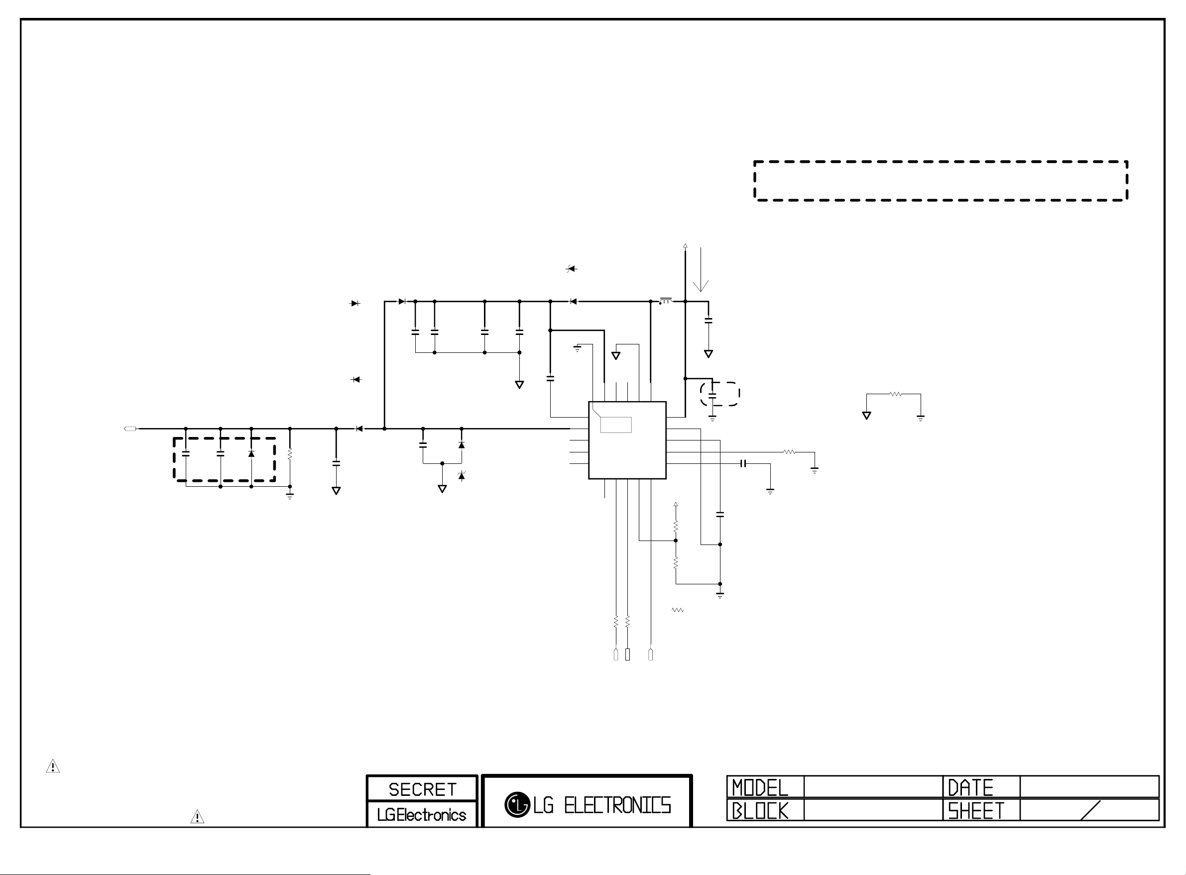
DVB-S2 LNB Part Allegro
Copyright ⓒ 2015 LG Electronics. Inc. All right reserved.
Only for training and service purposes
LGE Internal Use Only
PAGE 26
LNB_OUT
(Option:LNB)
C6900
0.1uF
LNB
Close to Tuner
Surge protectioin
C6901
33pF
LNB
D6900
LNB
R6900
2.2K
1W
LNB
LNB_TSC
SS23L
D6901-*1
LNB_TSC
D6901
MBR230LSFT1G
LNB_ONSEMI
C6902
0.22uF
LNB
25V
A_GND
2A
D6902-*1
SS23L
30V
30V
30V
D6902
LNB_ONSEMI
30V
C6903
0.01uF
50V
LNB
LNB
C6905
10uF
25V
LNB
close to Boost pin(#1)
C6904
0.1uF
50V
A_GND
C6906
10uF
25V
D6903
LNB_SMAB34
40V
D6903-*1
LNB_SX34
40V
LNB
A_GND
C6907
10uF
25V
LNB
LNB_SMAB34
LNB
C6908 0.1uF
D6904-*1
40V
LNB_SX34
D6904
40V
VCP
LNB
NC_1
TDI
TDO
A_GND
NC_2
NC_3
BOOST
[EP]GND
18
19
20
1
THERMAL
2
21
3
IC6900
A8303SESTR-T
4
LNB
5
7
8
6
SCL9ADD
SDA
IRQ
GNDLX
16LX17
10
TONECTRL
+12V
3.5A
LNB
15uH
L6900
SP-7850_15
VIN
15
GND
14
VREG
13
ISET
12
TCAP
11
+3.3V_NORMAL
3.3K
R6907
LNB_DMB
3A
Max 1.3A
C6909
10uF
25V
LNB
A_GND
close to VIN pin(#15)
C6910
0.1uF
50V
LNB
C6912
LNB
0.1uF
LNB
C6911 0.22uF
Input trace widths should be sized to conduct at least 3A
Ouput trace widths should be sized to conduct at least 2A
LNB
R6903
39K
1/16W
1%
Caution!! need isolated GND
A_GND
R6904
0
THE SYMBOL MARK OF THIS SCHEMETIC DIAGRAM INCORPORATES
SPECIAL FEATURES IMPORTANT FOR PROTECTION FROM X-RADIATION.
FIRE AND ELECTRICAL SHOCK HAZARDS, WHEN SERVICING IF IS
ESSENTIAL THAT ONLY MANUFACTURES SPECIFIED PARTS BE USED FOR
THE CRITICAL COMPONENTS IN THE SYMBOL MARK OF THE SCHEMETIC.
LNB
R6901 33
I2C_SCL4
LNB
R6902 33
I2C_SDA4
LNB_TX
10K
R6906
LNB_DMB
LNB_ALEGRO
R6906-*1
0
LNB
2012.03.08
69
Page 53
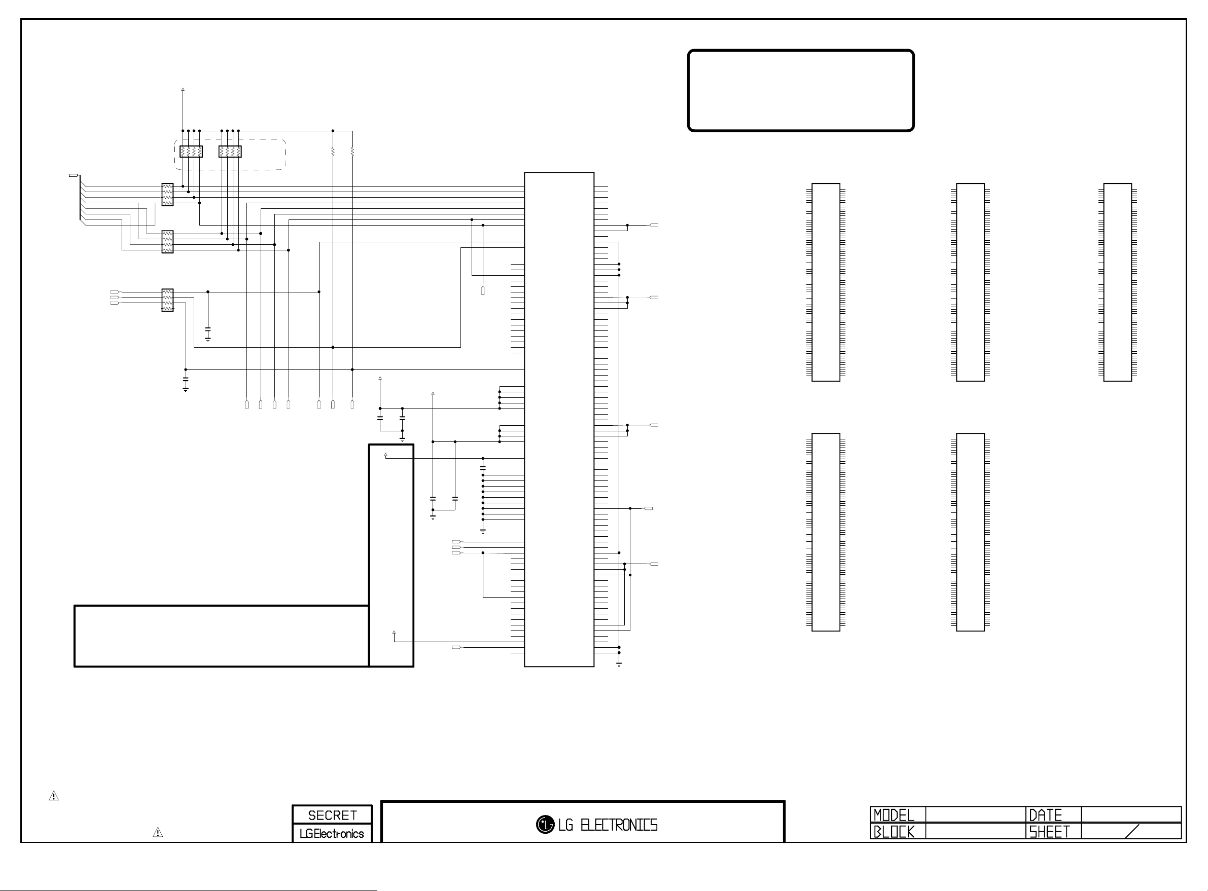
eMMC I/F
Copyright ⓒ 2015 LG Electronics. Inc. All right reserved.
Only for training and service purposes
LGE Internal Use Only
DVDD18_EMMC
3.3v power delete, 131120
* A0 / A1 : Use EMMC_4.41
* B0 : Use EMMC_4.5
(130923_Jihwan Hyun)
PAGE 30
10K
1/16W
AR8104
EMMC_DATA[0-7]
EMMC_DATA[0]
EMMC_DATA[1]
EMMC_DATA[2]
EMMC_DATA[3]
EMMC_DATA[4]
EMMC_DATA[5]
EMMC_DATA[6]
EMMC_DATA[7]
EMMC_CLK
EMMC_CMD
EMMC_RST
AR8100
22
1/16W
AR8101
22
1/16W
AR8102 22
C8107
10pF
OPT
50V
C8100
0.1uF
OPT
16V
Don’t Connect Power At VDDI
(Just Interal LDO Capacitor)
1/16W
DAT3
10K
AR8103
DAT4
DAT5
DAT6
10K
R8117
EMMC_CMD_BALL
EMMC_CLK_BALL
10K
R8116
DVDD18_EMMC
EMMC_RESET_BALL
C8105
0.1uF
16V
EMMC_VDDI
EMMC_VDDI
C8106
2.2uF
10V
3.3V_EMMC
C8102
0.1uF
16V
DAT3
DAT4
DAT7
DAT5
pattern 0.2mm
C8103
2.2uF
10V
DAT7
C8104
1uF
10V
THGBMAG6A2JBAIR
A3
DAT0
A4
DAT1
A5
DAT2
B2
DAT3
B3
DAT4
B4
DAT5
B5
DAT6
B6
DAT7
M6
CLK
M5
CMD
A6
RFU_1
A7
RFU_2
C5
NC_21
E5
RFU_3
E8
RFU_4
E9
RFU_5
E10
RFU_6
F10
RFU_7
G3
RFU_8
G10
RFU_9
H5
RFU_10
J5
RFU_11
K6
RFU_12
K7
RFU_13
K10
RFU_14
P7
RFU_15
P10
RFU_16
K5
RST_N
C6
VCCQ_1
M4
VCCQ_2
N4
VCCQ_3
P3
VCCQ_4
P5
VCCQ_5
E6
VCC_1
F5
VCC_2
J10
VCC_3
K9
VCC_4
C2
VDDI
E7
VSS_1
G5
VSS_2
H10
VSS_3
K8
VSS_4
C4
VSSQ_1
N2
VSSQ_2
N5
VSSQ_3
P4
VSSQ_4
P6
VSSQ_5
A1
NC_1
A2
NC_2
A8
NC_3
A9
NC_4
A10
NC_5
A11
NC_6
A12
NC_7
A13
NC_8
A14
NC_9
B1
NC_10
B7
NC_11
B8
NC_12
B9
NC_13
B10
NC_14
B11
NC_15
B12
NC_16
B13
NC_17
B14
NC_18
C1
NC_19
C3
NC_20
C7
NC_22
IC8100
C8
NC_23
C9
NC_24
C10
NC_25
C11
NC_26
C12
NC_27
C13
NC_28
C14
NC_29
D1
NC_30
D2
NC_31
D3
NC_32
D4
NC_33
D12
NC_34
D13
NC_35
D14
NC_36
E1
NC_37
E2
NC_38
E3
NC_39
E12
NC_40
E13
NC_41
E14
NC_42
F1
NC_43
F2
NC_44
F3
NC_45
F12
NC_46
F13
NC_47
F14
NC_48
G1
NC_49
G2
NC_50
G12
NC_51
G13
NC_52
G14
NC_53
H1
NC_54
H2
NC_55
H3
NC_56
H12
NC_57
H13
NC_58
H14
NC_59
J1
NC_60
J2
NC_61
J3
NC_62
J12
NC_63
J13
NC_64
J14
NC_65
K1
NC_66
K2
NC_67
K3
NC_68
K12
NC_69
K13
NC_70
K14
NC_71
L1
NC_72
L2
NC_73
L3
NC_74
L12
NC_75
L13
NC_76
L14
NC_77
M1
NC_78
M2
NC_79
M3
NC_80
NC_81
NC_82
NC_83
NC_84
NC_85
NC_86
NC_87
NC_88
NC_89
NC_90
NC_91
NC_92
NC_93
NC_94
NC_95
NC_96
NC_97
NC_98
NC_99
NC_100
NC_101
NC_102
NC_103
NC_104
NC_105
NC_106
NC_107
M7
M8
M9
M10
M11
M12
M13
M14
N1
N3
N6
N7
N8
N9
N10
N11
N12
N13
N14
P1
P2
P8
P9
P11
P12
P13
P14
EMMC4.5_8G_TOSHIBA
DAT5
DAT6
EMMC_RESET_BALL
EMMC_CLK_BALL
EMMC_CMD_BALL
MTFC4GMCDM-1M WT
A3
DAT0
A4
DAT1
A5
DAT2
B2
DAT3
B3
DAT4
B4
DAT5
B5
DAT6
B6
DAT7
M6
CLK
M5
CMD
A6
RFU_1
A7
RFU_2
C5
NC_21
E5
RFU_3
E8
RFU_4
E9
RFU_5
E10
RFU_6
F10
RFU_7
G3
RFU_8
G10
RFU_9
H5
RFU_10
J5
RFU_11
K6
RFU_12
K7
RFU_13
K10
RFU_14
P7
RFU_15
P10
RFU_16
K5
RST_N
C6
VCCQ_1
M4
VCCQ_2
N4
VCCQ_3
P3
VCCQ_4
P5
VCCQ_5
E6
VCC_1
F5
VCC_2
J10
VCC_3
K9
VCC_4
C2
VDDI
E7
VSS_1
G5
VSS_2
H10
VSS_3
K8
VSS_4
C4
VSSQ_1
N2
VSSQ_2
N5
VSSQ_3
P4
VSSQ_4
P6
VSSQ_5
A1
NC_1
A2
NC_2
A8
NC_3
A9
NC_4
A10
NC_5
A11
NC_6
A12
NC_7
A13
NC_8
A14
NC_9
B1
NC_10
B7
NC_11
B8
NC_12
B9
NC_13
B10
NC_14
B11
NC_15
B12
NC_16
B13
NC_17
B14
NC_18
C1
NC_19
C3
NC_20
C7
NC_22
THGBMAG7A2JBAIR
A3
DAT0
A4
DAT1
A5
DAT2
B2
DAT3
B3
DAT4
B4
DAT5
B5
DAT6
B6
DAT7
M6
CLK
M5
CMD
A6
RFU_1
A7
RFU_2
C5
NC_21
E5
RFU_3
E8
RFU_4
E9
RFU_5
E10
RFU_6
F10
RFU_7
G3
RFU_8
G10
RFU_9
H5
RFU_10
J5
RFU_11
K6
RFU_12
K7
RFU_13
K10
RFU_14
P7
RFU_15
P10
RFU_16
K5
RST_N
C6
VCCQ_1
M4
VCCQ_2
N4
VCCQ_3
P3
VCCQ_4
P5
VCCQ_5
E6
VCC_1
F5
VCC_2
J10
VCC_3
K9
VCC_4
C2
VDDI
E7
VSS_1
G5
VSS_2
H10
VSS_3
K8
VSS_4
C4
VSSQ_1
N2
VSSQ_2
N5
VSSQ_3
P4
VSSQ_4
P6
VSSQ_5
A1
NC_1
A2
NC_2
A8
NC_3
A9
NC_4
A10
NC_5
A11
NC_6
A12
NC_7
A13
NC_8
A14
NC_9
B1
NC_10
B7
NC_11
B8
NC_12
B9
NC_13
B10
NC_14
B11
NC_15
B12
NC_16
B13
NC_17
B14
NC_18
C1
NC_19
C3
NC_20
C7
NC_22
IC8100-*1
IC8100-*3
C8
NC_23
C9
NC_24
C10
NC_25
C11
NC_26
C12
NC_27
C13
NC_28
C14
NC_29
D1
NC_30
D2
NC_31
D3
NC_32
D4
NC_33
D12
NC_34
D13
NC_35
D14
NC_36
E1
NC_37
E2
NC_38
E3
NC_39
E12
NC_40
E13
NC_41
E14
NC_42
F1
NC_43
F2
NC_44
F3
NC_45
F12
NC_46
F13
NC_47
F14
NC_48
G1
NC_49
G2
NC_50
G12
NC_51
G13
NC_52
G14
NC_53
H1
NC_54
H2
NC_55
H3
NC_56
H12
NC_57
H13
NC_58
H14
NC_59
J1
NC_60
J2
NC_61
J3
NC_62
J12
NC_63
J13
NC_64
J14
NC_65
K1
NC_66
K2
NC_67
K3
NC_68
K12
NC_69
K13
NC_70
K14
NC_71
L1
NC_72
L2
NC_73
L3
NC_74
L12
EMMC4.5_4G_MICRON
NC_75
L13
NC_76
L14
NC_77
M1
NC_78
M2
NC_79
M3
NC_80
M7
NC_81
M8
NC_82
M9
NC_83
M10
NC_84
M11
NC_85
M12
NC_86
M13
NC_87
M14
NC_88
N1
NC_89
N3
NC_90
N6
NC_91
N7
NC_92
N8
NC_93
N9
NC_94
N10
NC_95
N11
NC_96
N12
NC_97
N13
NC_98
N14
NC_99
P1
NC_100
P2
NC_101
P8
NC_102
P9
NC_103
P11
NC_104
P12
NC_105
P13
NC_106
P14
NC_107
C8
NC_23
C9
NC_24
C10
NC_25
C11
NC_26
C12
NC_27
C13
NC_28
C14
NC_29
D1
NC_30
D2
NC_31
D3
NC_32
D4
NC_33
D12
NC_34
D13
NC_35
D14
NC_36
E1
NC_37
E2
NC_38
E3
NC_39
E12
NC_40
E13
NC_41
E14
NC_42
F1
NC_43
F2
NC_44
F3
NC_45
F12
NC_46
F13
NC_47
F14
NC_48
G1
NC_49
G2
NC_50
G12
NC_51
G13
NC_52
G14
NC_53
H1
NC_54
H2
NC_55
H3
NC_56
H12
NC_57
H13
NC_58
H14
NC_59
J1
NC_60
J2
NC_61
J3
NC_62
J12
NC_63
J13
NC_64
J14
NC_65
K1
NC_66
K2
NC_67
K3
NC_68
K12
NC_69
EMMC4.5_16G_TOSHIBA
K13
NC_70
K14
NC_71
L1
NC_72
L2
NC_73
L3
NC_74
L12
NC_75
L13
NC_76
L14
NC_77
M1
NC_78
M2
NC_79
M3
NC_80
M7
NC_81
M8
NC_82
M9
NC_83
M10
NC_84
M11
NC_85
M12
NC_86
M13
NC_87
M14
NC_88
N1
NC_89
N3
NC_90
N6
NC_91
N7
NC_92
N8
NC_93
N9
NC_94
N10
NC_95
N11
NC_96
N12
NC_97
N13
NC_98
N14
NC_99
P1
NC_100
P2
NC_101
P8
NC_102
P9
NC_103
P11
NC_104
P12
NC_105
P13
NC_106
P14
NC_107
A3
DAT0
A4
DAT1
A5
DAT2
B2
DAT3
B3
DAT4
B4
DAT5
B5
DAT6
B6
DAT7
M6
CLK
M5
CMD
A6
RFU_1
A7
RFU_2
C5
NC_21
E5
RFU_3
E8
RFU_4
E9
RFU_5
E10
RFU_6
F10
RFU_7
G3
RFU_8
G10
RFU_9
H5
RFU_10
J5
RFU_11
K6
RFU_12
K7
RFU_13
K10
RFU_14
P7
RFU_15
P10
RFU_16
K5
RST_N
C6
VCCQ_1
M4
VCCQ_2
N4
VCCQ_3
P3
VCCQ_4
P5
VCCQ_5
E6
VCC_1
F5
VCC_2
J10
VCC_3
K9
VCC_4
C2
VDDI
E7
VSS_1
G5
VSS_2
H10
VSS_3
K8
VSS_4
C4
VSSQ_1
N2
VSSQ_2
N5
VSSQ_3
P4
VSSQ_4
P6
VSSQ_5
A1
NC_1
A2
NC_2
A8
NC_3
A9
NC_4
A10
NC_5
A11
NC_6
A12
NC_7
A13
NC_8
A14
NC_9
B1
NC_10
B7
NC_11
B8
NC_12
B9
NC_13
B10
NC_14
B11
NC_15
B12
NC_16
B13
NC_17
B14
NC_18
C1
NC_19
C3
NC_20
C7
NC_22
A3
DAT0
A4
DAT1
A5
DAT2
B2
DAT3
B3
DAT4
B4
DAT5
B5
DAT6
B6
DAT7
M6
CLK
M5
CMD
A6
RFU_1
A7
RFU_2
C5
NC_21
E5
RFU_3
E8
RFU_4
E9
RFU_5
E10
RFU_6
F10
RFU_7
G3
RFU_8
G10
RFU_9
H5
RFU_10
J5
RFU_11
K6
RFU_12
K7
RFU_13
K10
RFU_14
P7
RFU_15
P10
RFU_16
K5
RST_N
C6
VCCQ_1
M4
VCCQ_2
N4
VCCQ_3
P3
VCCQ_4
P5
VCCQ_5
E6
VCC_1
F5
VCC_2
J10
VCC_3
K9
VCC_4
C2
VDDI
E7
VSS_1
G5
VSS_2
H10
VSS_3
K8
VSS_4
C4
VSSQ_1
N2
VSSQ_2
N5
VSSQ_3
P4
VSSQ_4
P6
VSSQ_5
A1
NC_1
A2
NC_2
A8
NC_3
A9
NC_4
A10
NC_5
A11
NC_6
A12
NC_7
A13
NC_8
A14
NC_9
B1
NC_10
B7
NC_11
B8
NC_12
B9
NC_13
B10
NC_14
B11
NC_15
B12
NC_16
B13
NC_17
B14
NC_18
C1
NC_19
C3
NC_20
C7
NC_22
MTFC8GLCDM-1M WT
THGBMAG5A1JBAIR
IC8100-*2
C8
NC_23
C9
NC_24
C10
NC_25
C11
NC_26
C12
NC_27
C13
NC_28
C14
NC_29
D1
NC_30
D2
NC_31
D3
NC_32
D4
NC_33
D12
NC_34
D13
NC_35
D14
NC_36
E1
NC_37
E2
NC_38
E3
NC_39
E12
NC_40
E13
NC_41
E14
NC_42
F1
NC_43
F2
NC_44
F3
NC_45
F12
NC_46
F13
NC_47
F14
NC_48
G1
NC_49
G2
NC_50
G12
NC_51
G13
NC_52
G14
NC_53
H1
NC_54
H2
NC_55
H3
NC_56
H12
NC_57
H13
NC_58
H14
NC_59
J1
NC_60
J2
NC_61
J3
NC_62
J12
NC_63
J13
NC_64
J14
NC_65
K1
NC_66
K2
NC_67
K3
NC_68
K12
NC_69
K13
NC_70
K14
NC_71
L1
NC_72
L2
NC_73
L3
NC_74
L12
EMMC4.5_8G_MICRON
NC_75
L13
NC_76
L14
NC_77
M1
NC_78
M2
NC_79
M3
NC_80
M7
NC_81
M8
NC_82
M9
NC_83
M10
NC_84
M11
NC_85
M12
NC_86
M13
NC_87
M14
NC_88
N1
NC_89
N3
NC_90
N6
NC_91
N7
NC_92
N8
NC_93
N9
NC_94
N10
NC_95
N11
NC_96
N12
NC_97
N13
NC_98
N14
NC_99
P1
NC_100
P2
NC_101
P8
NC_102
P9
NC_103
P11
NC_104
P12
NC_105
P13
NC_106
P14
NC_107
IC8100-*4
C8
NC_23
C9
NC_24
C10
NC_25
C11
NC_26
C12
NC_27
C13
NC_28
C14
NC_29
D1
NC_30
D2
NC_31
D3
NC_32
D4
NC_33
D12
NC_34
D13
NC_35
D14
NC_36
E1
NC_37
E2
NC_38
E3
NC_39
E12
NC_40
E13
NC_41
E14
NC_42
F1
NC_43
F2
NC_44
F3
NC_45
F12
NC_46
F13
NC_47
F14
NC_48
G1
NC_49
G2
NC_50
G12
NC_51
G13
NC_52
G14
NC_53
H1
NC_54
H2
NC_55
H3
NC_56
H12
NC_57
H13
NC_58
H14
NC_59
J1
NC_60
J2
NC_61
J3
NC_62
J12
NC_63
J13
NC_64
J14
NC_65
K1
NC_66
K2
NC_67
K3
NC_68
K12
NC_69
EMMC4.5_4G_TOSHIBA
K13
NC_70
K14
NC_71
L1
NC_72
L2
NC_73
L3
NC_74
L12
NC_75
L13
NC_76
L14
NC_77
M1
NC_78
M2
NC_79
M3
NC_80
M7
NC_81
M8
NC_82
M9
NC_83
M10
NC_84
M11
NC_85
M12
NC_86
M13
NC_87
M14
NC_88
N1
NC_89
N3
NC_90
N6
NC_91
N7
NC_92
N8
NC_93
N9
NC_94
N10
NC_95
N11
NC_96
N12
NC_97
N13
NC_98
N14
NC_99
P1
NC_100
P2
NC_101
P8
NC_102
P9
NC_103
P11
NC_104
P12
NC_105
P13
NC_106
P14
NC_107
H26M31003GMR
A3
DAT0
A4
DAT1
A5
DAT2
B2
DAT3
B3
DAT4
B4
DAT5
B5
DAT6
B6
DAT7
M6
CLK
M5
CMD
A6
RFU_1
A7
RFU_2
C5
NC_21
E5
RFU_3
E8
RFU_4
E9
RFU_5
E10
RFU_6
F10
RFU_7
G3
RFU_8
G10
RFU_9
H5
RFU_10
J5
RFU_11
K6
RFU_12
K7
RFU_13
K10
RFU_14
P7
RFU_15
P10
RFU_16
K5
RST_N
C6
VCCQ_1
M4
VCCQ_2
N4
VCCQ_3
P3
VCCQ_4
P5
VCCQ_5
E6
VCC_1
F5
VCC_2
J10
VCC_3
K9
VCC_4
C2
VDDI
E7
VSS_1
G5
VSS_2
H10
VSS_3
K8
VSS_4
C4
VSSQ_1
N2
VSSQ_2
N5
VSSQ_3
P4
VSSQ_4
P6
VSSQ_5
A1
NC_1
A2
NC_2
A8
NC_3
A9
NC_4
A10
NC_5
A11
NC_6
A12
NC_7
A13
NC_8
A14
NC_9
B1
NC_10
B7
NC_11
B8
NC_12
B9
NC_13
B10
NC_14
B11
NC_15
B12
NC_16
B13
NC_17
B14
NC_18
C1
NC_19
C3
NC_20
C7
NC_22
IC8100-*5
C8
NC_23
C9
NC_24
C10
NC_25
C11
NC_26
C12
NC_27
C13
NC_28
C14
NC_29
D1
NC_30
D2
NC_31
D3
NC_32
D4
NC_33
D12
NC_34
D13
NC_35
D14
NC_36
E1
NC_37
E2
NC_38
E3
NC_39
E12
NC_40
E13
NC_41
E14
NC_42
F1
NC_43
F2
NC_44
F3
NC_45
F12
NC_46
F13
NC_47
F14
NC_48
G1
NC_49
G2
NC_50
G12
NC_51
G13
NC_52
G14
NC_53
H1
NC_54
H2
NC_55
H3
NC_56
H12
NC_57
H13
NC_58
H14
NC_59
J1
NC_60
J2
NC_61
J3
NC_62
J12
NC_63
J13
NC_64
J14
NC_65
K1
NC_66
K2
NC_67
K3
NC_68
K12
NC_69
K13
NC_70
K14
NC_71
L1
NC_72
L2
NC_73
L3
NC_74
L12
EMMC4.5_4G_SKHynix
NC_75
L13
NC_76
L14
NC_77
M1
NC_78
M2
NC_79
M3
NC_80
M7
NC_81
M8
NC_82
M9
NC_83
M10
NC_84
M11
NC_85
M12
NC_86
M13
NC_87
M14
NC_88
N1
NC_89
N3
NC_90
N6
NC_91
N7
NC_92
N8
NC_93
N9
NC_94
N10
NC_95
N11
NC_96
N12
NC_97
N13
NC_98
N14
NC_99
P1
NC_100
P2
NC_101
P8
NC_102
P9
NC_103
P11
NC_104
P12
NC_105
P13
NC_106
P14
NC_107
THE SYMBOL MARK OF THIS SCHEMETIC DIAGRAM INCORPORATES
SPECIAL FEATURES IMPORTANT FOR PROTECTION FROM X-RADIATION.
FIRE AND ELECTRICAL SHOCK HAZARDS, WHEN SERVICING IF IS
ESSENTIAL THAT ONLY MANUFACTURES SPECIFIED PARTS BE USED FOR
THE CRITICAL COMPONENTS IN THE SYMBOL MARK OF THE SCHEMETIC.
eMMC
11.09.29
81
Page 54
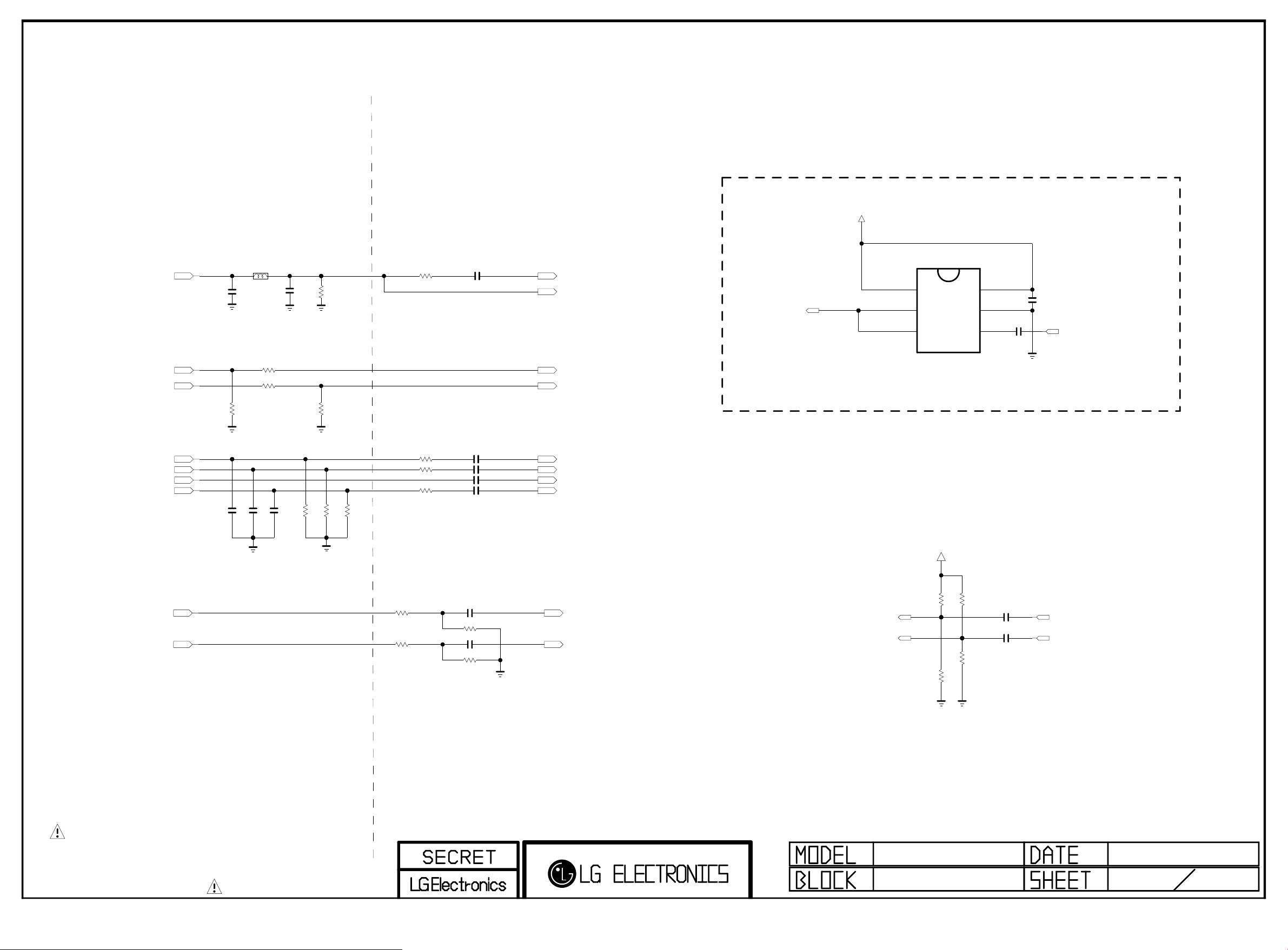
PLACE AT JACK SIDE
Copyright ⓒ 2015 LG Electronics. Inc. All right reserved.
Only for training and service purposes
LGE Internal Use Only
SCART SIGNAL
(Use only EU/CIS Model)
Place JACK Side
SC_CVBS_IN
SC_FB
SC_ID
SC_B
SC_G
SC_CVBS_IN_SOY
SC_R
C302
150pF
50V
EU
R305
R306 10K
R302
75
EU
10pF
C304
50V
OPT
L302
EU
C307
EU
EU
10pF
50V
OPT
1uH
C308
100
10pF
50V
OPT
C311
150pF
EU
75
1%
1005
R313
EU
3216
1005
EU
R315
75
EU
R316
2.7K
75
1%
R317
EU
1005
75
1%
R319
Place SOC Side
+3.3V_NORMAL
IC300
VOUT
VSAG
NJM2561BF1
1
2
3
+12V
EU
GND
5
VIN
EU
4
C363
0.1uF
EU
C362
0.1uF
DTV/MNT_V_OUT_SOC
V+
6
AUDIO OUT
100
C326 0.047uF
SC_CVBS_IN_SOC
POWER_SAVE
R328
EU
EU
SC_CVBS_IN_SOY
DTV/MNT_V_OUT
SC_FB_SOC
SC_ID_SOC
33
R330
EU
R331 33
EU
R332 33
EU
EU
EU
C319 0.047uF
EU
C320 0.047uF
EU
C327 1000pF
C321 0.047uF
EU
COMP1_PB_IN_SOC
COMP1_Y_IN_SOC
COMP1_Y_IN_SOC_SOY
COMP1_PR_IN_SOC
AUDIO IN
EU
SC_L_IN
SC_R_IN
R307 27K
EU
1%
R308 27K
EU
1%
C314 4.7uF
EU
R320 10K
1%
EU
C315 4.7uF
R321 10K
EU
1%
AUAD_L_CH2_IN
AUAD_R_CH2_IN
THE SYMBOL MARK OF THIS SCHEMETIC DIAGRAM INCORPORATES
SPECIAL FEATURES IMPORTANT FOR PROTECTION FROM X-RADIATION.
FIRE AND ELECTRICAL SHOCK HAZARDS, WHEN SERVICING IF IS
ESSENTIAL THAT ONLY MANUFACTURES SPECIFIED PARTS BE USED FOR
THE CRITICAL COMPONENTS IN THE SYMBOL MARK OF THE SCHEMETIC.
SCART_LOUT
SCART_ROUT
EU
R336
100K
R337
100K
EU
R338
100K
EU
C329 2.2uF
C330 2.2uF
EU
R339
100K
10V
EU
10V
EU
SCART_LOUT_SOC
SCART_ROUT_SOC
Page 55
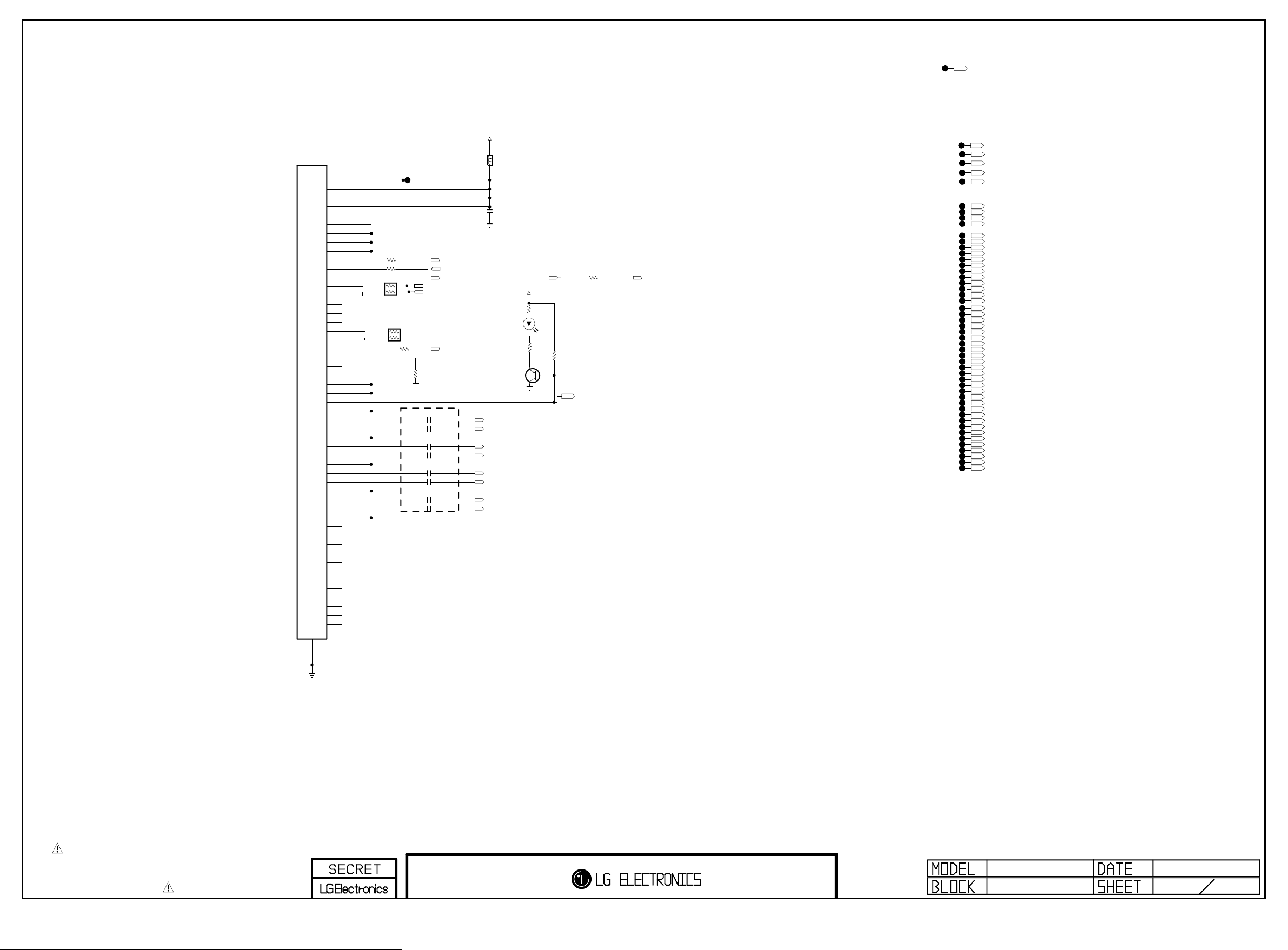
Vx1 Interface
Copyright ⓒ 2015 LG Electronics. Inc. All right reserved.
Only for training and service purposes
LGE Internal Use Only
EPI_CTL
PAGE 27
[51Pin LVDS OUTPUT Connector]
P11401
FI-RE51S-HF-J-R1500
LVDS_Vby1
VCC
1
VCC
2
VCC
3
VCC
4
NC
5
GND
6
GND
7
GND
8
GND
52
GND
9
RS_DONE
10
ELVDD_ON
11
BURNT_DET
12
I2C_SDA
13
I2C_SCL
14
NC
15
NC
16
NC
17
NC
18
NC
19
MODULE_20V_DET
20
LVDS_SEL
21
NC
22
NC
23
GND
24
GND
25
LOCKN
26
GND
27
TX1N
28
TX1P
29
GND
30
TX2N
31
TX2P
32
GND
33
TX3N
34
TX3P
35
GND
36
TX4N
37
TX4P
38
GND
39
NC
40
NC
41
NC
42
NC
43
NC
44
NC
45
NC
46
NC
47
NC
48
NC
49
NC
50
NC
51
R11401
R11402
MV14_I2C
AR11402
33
VBY1_LVDS_JIG_I2C
AR11403
33
0
0
0
R12013
LVDS_BIT_SEL_LOW
OLED:2D/3D_CTL=RS_DONE
2D/3D_CTL
INV_CTL
T_CON_SYS_POWER_OFF
I2C_SDA1
I2C_SCL1
MODULE_20V_DET
R11403
10K
C114010.1uF
C114020.1uF
C114030.1uF
C114040.1uF
C114050.1uF
C114060.1uF
C114070.1uF
C114080.1uF
PANEL_VCC
L11401
BLM18PG121SN1D
C11409
10uF
OPT
16V
T_CON_SYS_POWER_OFF
MMBT3906(NXP)
Close to SoC
TXA2N/TX9N
TXA2P/TX9P
TXACLKN/TX8N
TXACLKP/TX8P
TXA3N/TX7N
TXA3P/TX7P
TXA4N/TX6N
TXA4P/TX6P
+2.5V_NORMAL
R11404
22
LD11401
SML-512UW
R11405
220
E
Q11401
B
C
TX6/7/8/9 : V BY 1
R11406
10K
R11408
0
EPI_LOCK8/6
LED_R
IRB_DATA
IRB_3.3V
PWM_DIM
IR_B_RESET
OPC_EN
MCLK_SOC
GCLK_SOC
EO_SOC
GST_SOC
TXB4N/TX0N
TXB4P/TX0P
TXB3N/TX1N
TXB3P/TX1P
TXBCLKN/TX2N
TXBCLKP/TX2P
TXB2N/TX3N
TXB2P/TX3P
TXB1N/TX4N
TXB1P/TX4P
TXB0N/TX5N
TXB0P/TX5P
TXA1N/TX10N
TXA1P/TX10P
TXA0N/TX11N
TXA0P/TX11P
TXD4N/TX12N
TXD4P/TX12P
TXD3N/TX13N
TXD3P/TX13P
TXDCLKN/TX14N
TXDCLKP/TX14P
TXD2N/TX15N
TXD2P/TX15P
TXD1N/TX16N
TXD1P/TX16P
TXD0N/TX17N
TXD0P/TX17P
TXC4N/TX18N
TXC4P/TX18P
TXC3N/TX19N
TXC3P/TX19P
TXCCLKN/TX20N
TXCCLKP/TX20P
TXC2N/TX21N
TXC2P/TX21P
TXC1N/TX22N
TXC1P/TX22P
TXC0N/TX23N
TXC0P/TX23P
THE SYMBOL MARK OF THIS SCHEMETIC DIAGRAM INCORPORATES
SPECIAL FEATURES IMPORTANT FOR PROTECTION FROM X-RADIATION.
FIRE AND ELECTRICAL SHOCK HAZARDS, WHEN SERVICING IF IS
ESSENTIAL THAT ONLY MANUFACTURES SPECIFIED PARTS BE USED FOR
THE CRITICAL COMPONENTS IN THE SYMBOL MARK OF THE SCHEMETIC.
MID_LG1311
Vx1 LVDS INTERFACE
BSD-NC4_H072-HD
2013.04.03
Page 56
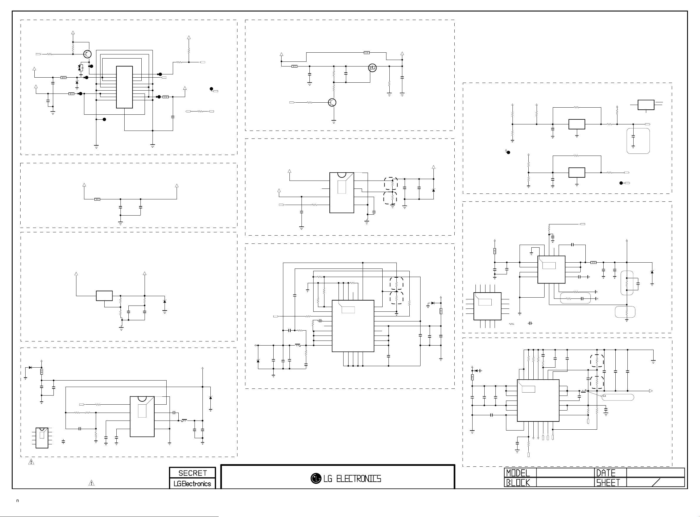
+3.5V_ST
Copyright ⓒ 2015 LG Electronics. Inc. All right reserved.
Only for training and service purposes
LGE Internal Use Only
+3.3V_NORMAL
RL_ON
+3.5V_ST
+12V
C2306
0.1uF
R2301
MMBT3906(NXP)
AMOTECH CO., LTD.
L2304
UBW2012-121F
C2307
0.1uF
16V
UBW2012-121F
10K
VA23001
L2303
R2300
10K
50V
5.6V
Q2300
2
5V
ZD2303
1
3
P2300
SMAW200-H18S5
POWER_WAFER_18PIN
PWR ON
1
3.5V
3
3.5V
5
GND
7
24V
9
GND
11
12V
13
12V
15
GND
17
19
INV ON
2
NC
4
3.5V
6
GND
8
24V
10
GND
12
12V
14
24V
16
GND
18
ECO_POWER_CTL
L2306
UBW2012-121F
C2316
0.1uF
50V
R2309
100
+24V
R2310
1K
OPT
R12014
0
1/16W
5%
INV_CTL
TP5603
PWM_DIM2
MODEL_OPT_11ECO_POWER_CTL
+3.3V - eMMC 4.41(LG1311-A0)
+3.3V_NORMAL
L2302
BLM18PG121SN1D
C2305
0.1uF
16V
C2300
22uF
10V
3.3V_EMMC
+1.8V - eMMC 4.51(LG1311-B0)
+3.3V_NORMAL
IC2306
AZ1117EH-ADJTRG1
OUTIN
ADJ/GND
+12V
D2304
PTVS13VS1UR
OPT
13V
EN
VFB
VREG5
SS
TPS54327DDAR
L2300
BLM18PG121SN1D
C2302
10uF
16V
3.3V_DCDC_TI
IC2300-*1
1
9
2
THERMAL
3
4
[EP]GND
VIN
8
VBST
7
SW
6
GND
5
+3.3V_NORMAL
C2303
0.1uF
25V
R23 03
68K
1/1 6W
1%
R2304
10K
1/1 6W
1%
3.3V_DCDC_TI
C2312-*1
3300pF
50V
POWER_ON/OFF1
R2302
5.1K
1/16W
1%
C2304
100pF
50V
C2310
R23 05
22K
1uF
10V
THE SYMBOL MARK OF THIS SCHEMETIC DIAGRAM INCORPORATES
SPECIAL FEATURES IMPORTANT FOR PROTECTION FROM X-RADIATION.
FIRE AND ELECTRICAL SHOCK HAZARDS, WHEN SERVICING IF IS
ESSENTIAL THAT ONLY MANUFACTURES SPECIFIED PARTS BE USED FOR
THE CRITICAL COMPONENTS IN THE SYMBOL MARK OF THE SCHEMETIC.
DVDD18_EMMC
R2357
75
R2358
33
VREG
C2312
2200pF
50V
DCDC_ROHM
C2301
10uF
10V
IC2300
BD9D320EFJ
EN
1
FB
2
3
DEV_BD9D320EFJ_E2
SS
4
3A
R2347
1
C2308
10uF
10V
9
THERMAL
8
7
6
5
[EP]FIN
VIN
BOOT
SW
GND
OPT
2.5V
D2302
16V
0.1uF
C2313
Vout=0.765*(1+R1/R2)
L2301
2uH
C2314
22uF
10V
+3.3V_NORMAL
C2315
22uF
10V
5V
ZD2300
OPT
PANEL_CTL
+5V_NORMAL
POWER_ON/OFF2_1
POWER_ON/OFF2_3
+1.1V_VDD
C2317
22uF
10V
OPT
2.5V
ZD2301
PANEL_POWER
PANEL_VCC_DIRECT
C2333
10uF
16V
UBW2012-121F
+12V
PANEL_VCC_FET
L2313
UBW2012-121F
R2314
10K
C2331
0.1uF
50V
R2317
R2318
5.1K
B
30K
C
Q2301
MMBT3904(NXP)
E
+2.5V
AP7173-SPG-13 HF(DIODES)
+3.3V_NORMAL
C2327
10uF
10V
R2312
10K
IC2302
IN
1
PG
2
VCC
1.5A
3
EN
4
9
THERMAL
[EP]
OUT
8
FB
7
SS
6
GND
5
+1.1V_CORE
R2311
10K C2342
1%
R2351
5%
91K
1/1 6W
R23 15
1%
27K
1/1 6W
RF
R23 13
PGOOD
EN
C2323
VBST
0.1uF
NC_1
16V
SW_1
SW_2
SW_3
SW_4
C2318
22uF
10V
C2320
0.1uF
16V
C2319
22uF
10V
L2305
1uH
C2321
1000pF
50V
R2307 1K
R2306
2K
1/16W
5%
R2308
3.3
4.7
1/10W
C2322
470pF
50V
Vout=0.6*(1+R1/R2)
POWER UP SEQUENCE
5V/3.3V->2.5V->1.5V/1.1V->1.0V
[EP]
1
THERMAL
2
29
3
IC2301
4
TPS53513RVER
5
DEV_TPS53513RVER
6
7
8
9
10
PGND_111PGND_212PGND_313PGND_414PGND_5
R2316
39K
1/16W
5%
TRIP26NC_327GND128GND2
L12007
Q2302
PMV48XP
S
G
D
C9100
2200pF
50V
PANEL_VCC
R2346
3.3K
LVDS_DISCHARGE
R1
1%
4.3K
1/16W
R2322
1%
R2
2K
1/16W
R2321
Vout=0.8*(1+R1/R2)
R1
R2319
9.1K
1/16W
1%
R2
R2320
10.7K
1/16W
C2325
2200pF
50V
1%
24VO25
FB
23
GND
22
MODE
21
VREG
20
VDD
19
NC_2
18
VIN_3
17
VIN_2
16
VIN_1
15
C2347
0.1uF
50V
+2.5V_NORMAL
C2346
10uF
C2337
10V
0.1uF
16V
5%
20K
R2323
1/16W
C2326
1uF
10V
D2303
PTVS13VS1UR
OPT
13V
OPT
L2307
C2328
10uF
16V
5V
D2301
+12V
C2332
10uF
16V
Power_DET
+12V
P_DET_12V
P_DET_12V
PANEL_20V
TP5602
On-semi
R2325
2.7K
1%
R2326
1.2K
1%
P_DET_3.5V
PANEL_20V
OPT
OPT
+3.5V_ST
R2327
8.2K
R2328
1.5K
1%
R2330
0
5%
OPT
DDR MAIN 1.5V
10K
R2324
1.5V_DCDC_TI
+3.5V_ST
VIN_1
VIN_2
GND_1
GND_2
VIN_3
EP[GND]
1.5V_DCDC_TI
1
THERMAL
2
IC2303-*1
3
TPS54319TRE
4
5
AGND
15EN16
17
6
VSENSE
COMP
7
C2339
10uF
10V
BOOT14PWRGD
13
12
11
10
8
RT/CLK
L2308
9
C2340
0.1uF
16V
PH_3
PH_2
PH_1
SS/TR
1.5V_DCDC_TI
R2329-*1
15K
1/16W
PVIN_1
PVIN_2
PGND_1
PGND_2
1.5V_DCDC_TI
C2344-*1
4700pF
[EP]FIN
1
THERMAL
DEV_T-BD9A300MUV_E2
2
17
IC2303
3
BD9A300MUV
4
3A
5
6
FB
AGND8MODE
Vout=0.8*(1+R1/R2)
+5.0V normal & USB
C2334
0.0068uF
50V
R2342
+12V
PTVS13VS1UR
13V
OPT
L2310
120-ohm
C2309
10uF
35V
OPT
D2305
C2311
10uF
35V
[EP]
VIN_1
1
THERMAL
VIN_2
2
VIN_3
C2329
0.1uF
50V
1uF
25V
C23 24
3
PGND_1
4
SN1302001(TPS65286RHDR)
PGND_2
5
PGND_3
6
V7V
7
8
MODE/SYNC
C2330
0.0068uF
50V
R2339
POWER_ON/OFF2_4
R23 35 1 6K 1%
R23 40 1 6K 1%
R23 4115 0K 1%
COMP25RLIM26RSET127RSET228AGND
29
DEV-TPS65286RHDR
IC2304
9EN10
12
SW_EN213SW_EN1
SW_OUT211SW_OUT1
10K
+5V_USB_3
+5V_USB_2
MID_LG1311
10K
USB_CTL3
USB_CTL2
RESET IC_ROHM
VDD
C2355
0.1uF
16V
VDD
C2356
0.1uF
50V
C4700
0.1uF
BOOT14PGD15EN16AVIN
13
SW_3
12
SW_2
11
SW_1
10
SS
9
7
ITH
R2329
8.2K
1/16W
1%
1.5V_DCDC_ROHM
OPT
C2335
100pF
50V
22SS23FB24
LX_3
21
LX_2
20
LX_1
19
BST
18
SW_IN2
17
SW_IN1
16
NFAULT1
15
14
NFAULT2
/USB_OCD2
POWER
R2337
100K
IC2307
BD48K28G
3
OPT
R2336
100K
OPT
IC2308
BD48K28G
3
C2341
0.1uF
16V
0.01uF
R2331
330K1/16W 5%
C2336
0.047uF
25V
VOUT
2
1
GND
VOUT
2
1
GND
POWER_ON/OFF2_2
50V
2700pF
C2344
50V
1.5V_DCDC_ROHM
C2343
82pF
50V
4.7uH
L2311
C2338
0.047uF
25V
5%
100K
R2344
1/16W
/USB_OCD3
NR5040T2R2N
L2309
2.2uH
R2
R1
R2353
R2350
100
R2349
100
C2349
C2345
22uF
22uF
10V
10V
1%
6.8K
1/16W
R2345
C2348
22uF
10V
1%
51K
1/16W
R2352
L2311 Change, 131120
for Currnet UP
5%
100K
1/16W
+3.5V_ST
OPT
TP5604
C2350
1uF
10V
Vout=0.6*(1+R1/R2)
PAGE 8
RESET IC_DIODES
IC2307-*1
APX803D29
VCC
3
R2338
10K
OPT
not to RESET at 8kV ESD
POWER_DET_MODULE
POWER_DET_MODULE
+1.5V_DDR
1%
R1
1/1 6W
R2
1%
1/1 6W
C2351
22uF
10V
1
GND
POWER_DET
C2365
0.1uF
16V
24V-->3.48V
12V-->3.58V
ST_3.5V-->3.5V
ZD2302
C8200
100pF
16K
50V
R23 32
1.5V_DCDC_TI
18K
R23 33
C2352
10uF
10V
+5V_NORMAL
2013.03.22
8
2.5V
RESET
2
OPT
31
Page 57
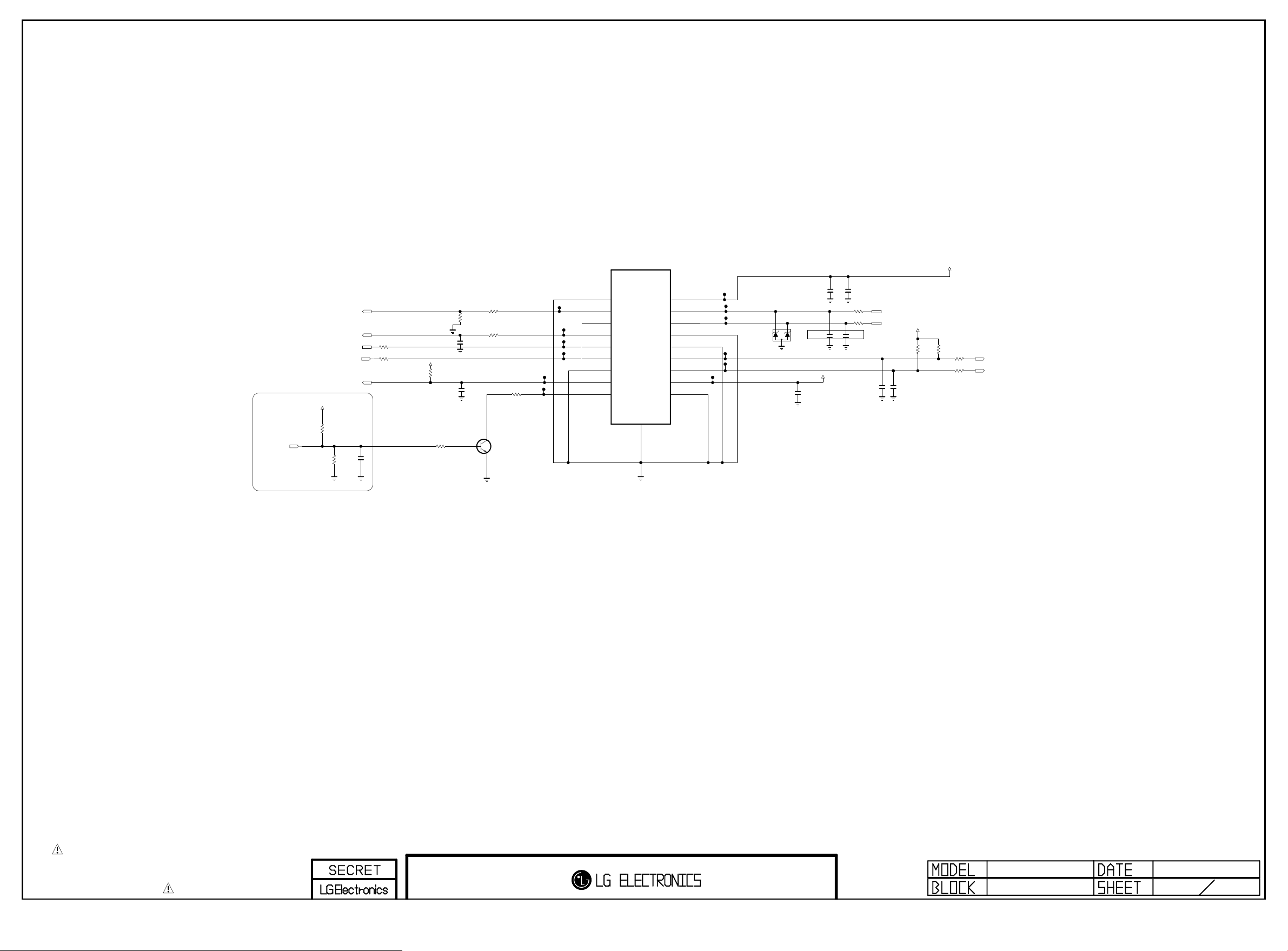
PAGE 12
Copyright ⓒ 2015 LG Electronics. Inc. All right reserved.
Only for training and service purposes
LGE Internal Use Only
LOGO_LIGHT
place Near Micom
BT_RESET
WOL/WIFI_POWER_ON
EYE_SDA
EYE_SCL
+3.5V_ST
OPT
R11601
10K
0.1uF
10K
C11601
R11602
P11601
+3.5V_ST
5%
OPT
R11615
10K
5%
+3.5V_WOL
R11616
R11617
100
KEY1
100
KEY2
SMAW200-H18S5
GND
NC
WOL
SDA
SCL
GND
IR
LOGO
1
3
5
7
9
11
13
15
17
R11609
100
1/16W
5%
2K
C11602
R11610
R11603
100
R11604
100
IR
R11606
10K
5%
C11603
0.1uF
+3.5V_ST
C11604
100pF
50V
100
R11611
22
BT_RESET
2
4
6
8
10
12
14
16
18
+3.5V_WOL
USB_DM
USB_DP
GND
GND
KEY1
KEY2
+3.5V_ST
GND
D11601
RCLAMP0502BA
L4000 Delete for voltage drop, 131120
OPT
55EC93_WIFI_EMI
C11605
1000pF
50V
OPT
C11607
0.1uF
Place Near Wafer
C11606
5pF
50V
55EC93_WIFI_EMI
+3.5V_ST
C11609
C11608
5pF
50V
22uF
10V
R11612
10
R11613
10
OPT
C11610
0.1uF
WIFI_DM
WIFI_DP
R11614
C11611
0.1uF
10K
19
1K
16V
B
MMBT3904(NXP)
E
C
Q11601
R11607
GND
THE SYMBOL MARK OF THIS SCHEMETIC DIAGRAM INCORPORATES
SPECIAL FEATURES IMPORTANT FOR PROTECTION FROM X-RADIATION.
FIRE AND ELECTRICAL SHOCK HAZARDS, WHEN SERVICING IF IS
ESSENTIAL THAT ONLY MANUFACTURES SPECIFIED PARTS BE USED FOR
THE CRITICAL COMPONENTS IN THE SYMBOL MARK OF THE SCHEMETIC.
MID_LG1311
IR / KEY
2013.03.22
12
31
Page 58
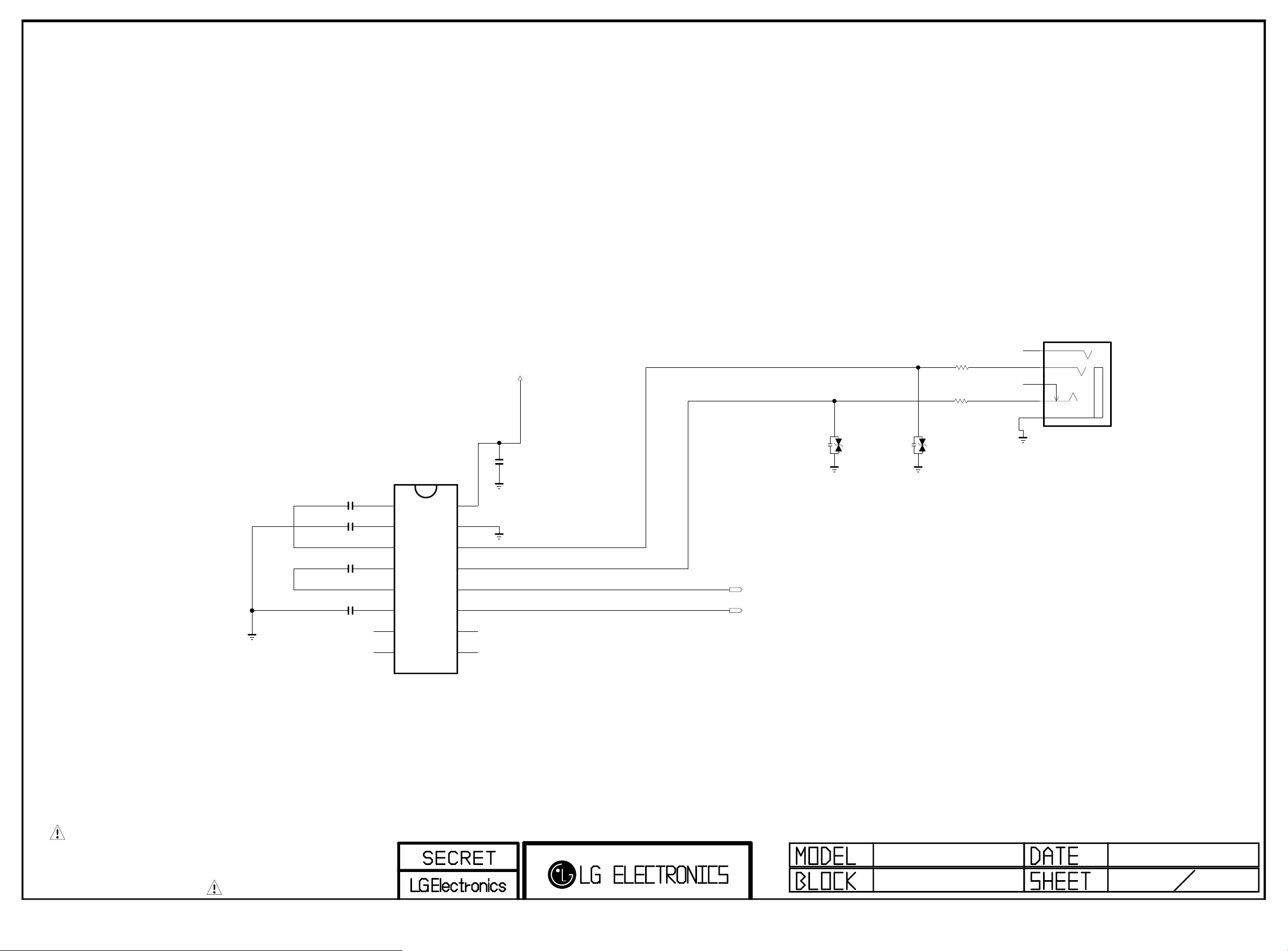
RS-232C Control INTERFACE(NORTH AMERICA)
Copyright ⓒ 2015 LG Electronics. Inc. All right reserved.
Only for training and service purposes
LGE Internal Use Only
RS232C
RS232C
RS232C
RS232C
C6808
0.1uF
C2809
0.1uF
C6810
0.1uF
C6811
0.1uF
C1+
C1-
C2+
C2-
DOUT2
RIN2
V+
V-
RS232C
IC6801
MAX3232CDR
1
2
3
4
5
6
7
8
EAN41348201
RS232C
R6820
+3.5V_ST
OPT
ZD6802
ADUC 20S 02 010L
RS232C
C6813
0.1uF
VCC
16
GND
15
DOUT1
14
RIN1
13
ROUT1
12
DIN1
11
DIN2
10
ROUT2
9
SOC_RX
SOC_TX
20V
100
RS232C
R6821
100
OPT
ZD6803
ADUC 20S 02 010L
20V
6M6
1M1
3M3_DETECT
4M4
5M5_GND
KJA-PH-1-0177
JK4303
THE SYMBOL MARK OF THIS SCHEMETIC DIAGRAM INCORPORATES
SPECIAL FEATURES IMPORTANT FOR PROTECTION FROM X-RADIATION.
FIRE AND ELECTRICAL SHOCK HAZARDS, WHEN SERVICING IF IS
ESSENTIAL THAT ONLY MANUFACTURES SPECIFIED PARTS BE USED FOR
THE CRITICAL COMPONENTS IN THE SYMBOL MARK OF THE SCHEMETIC.
Page 59
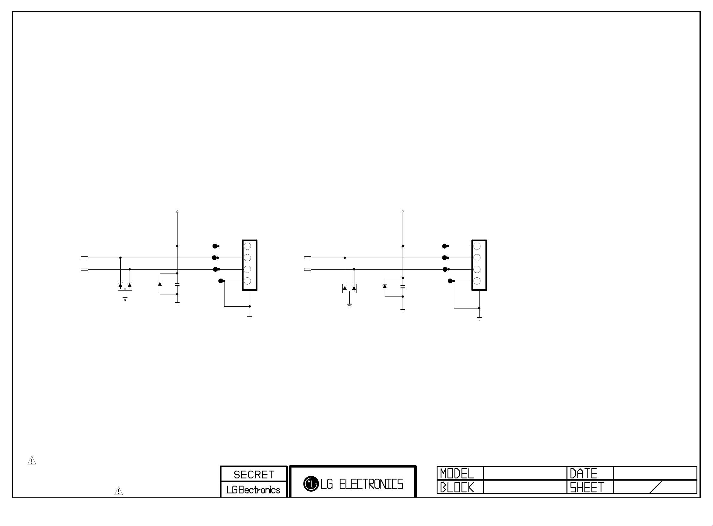
PAGE 13
Copyright ⓒ 2015 LG Electronics. Inc. All right reserved.
Only for training and service purposes
LGE Internal Use Only
USB_DM2
USB_DP2
D11801
RCLAMP0502BA
+5V_USB_2
C11806
5V
ZD4301
ESD_USB23
10uF
10V
USB2
MAX 1.5A
3AU04S-305- ZC- (LG)
JK4302
1234
+5V_USB_3
USB_DM3
USB_DP3
USB DOWN ST REA M
5
D11802
RCLAMP0502BA
C11812
5V
ZD4300
ESD_USB23
10uF
USB3
10V
USB3
MAX 1.5A
USB3
3AU04S-305- ZC- (LG)
JK4300
1234
USB DOWN STREAM
5
THE SYMBOL MARK OF THIS SCHEMETIC DIAGRAM INCORPORATES
SPECIAL FEATURES IMPORTANT FOR PROTECTION FROM X-RADIATION.
FIRE AND ELECTRICAL SHOCK HAZARDS, WHEN SERVICING IF IS
ESSENTIAL THAT ONLY MANUFACTURES SPECIFIED PARTS BE USED FOR
THE CRITICAL COMPONENTS IN THE SYMBOL MARK OF THE SCHEMETIC.
MID_LG1311
USB 2 & 3
2013.04.03
1
Page 60
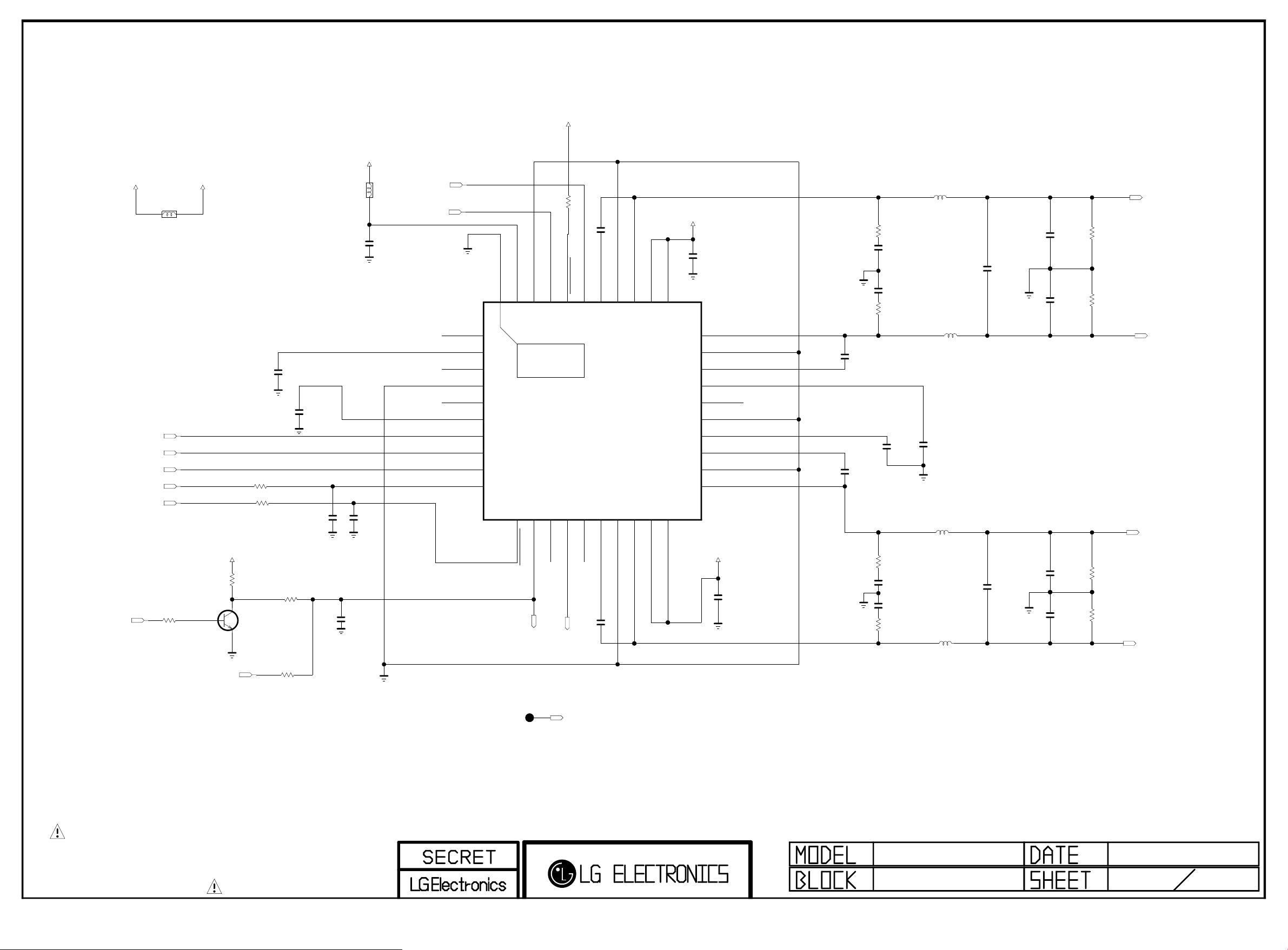
AUDIO AMP(NTP7514) TWEETER
Copyright ⓒ 2015 LG Electronics. Inc. All right reserved.
Only for training and service purposes
LGE Internal Use Only
+3.3V_NORMAL
PAGE 18
+3.3V_NORMAL
AMP_MUTE
+24V
UBW2012-121F
AUD_LRCH
AUD_LRCK
AUD_SCK
I2C_SDA1
I2C_SCL1
AMP_MUTE_MICOM
L11901
R11901
10K
+24V_AMP
POWER_DET
+3.3V_NORMAL
R11902
10K
AMP_MUTE_MICOM
C
B
Q11901
MMBT3904(NXP)
AMP_MUTE_MICOM
E
C11901
1uF
10V
R11903
100
R11904
100
AMP_MUTE_MICOM
R11906
100
AMP_MUTE_PWR_DET
R11905
100
L11902
BLM18PG121SN1D
C11902
1uF
10V
C11903
33pF
50V
AMP_MUTE_MICOM
C11904
1000pF
50V
C11906
0.1uF
16V
C11905
33pF
50V
AMP_RESET_N
AUD_MASTER_CLK
NC_1
VDD_PLL
NC_2
GND
NC_3
DVDD
SDATA
WCK
BCK
SDA
VDD_IO
[EP]GND
40
1
2
THERMAL
3
4
5
6
7
8
9
10
11
SCL
R12004
4.7K
AD
CLK_I
GND_IO
37
38
39
41
IC5600
NTP7514
12
13
14
FAULT
MONITOR_0
MONITOR_1
22000pF
I2S_AMP
WOOFER_MUTE
1/16W
5%
50V
C11907
22000pF
PGND1A
BST1A
RESET
34
35
36
0x56
15
16
17
BST2B
PGND2B
MONITOR_2
C11908
50V
PVDD1A
OUT1A
32
33
18
19
OUT2B
PVDD2B
+24V_AMP
PVDD1B
31
30
29
28
27
26
25
24
23
22
21
20
+24V_AMP
PVDD2A
C11909
10uF
35V
OUT1B
PGND1B
BST1B
VDR1
NC_4
AGND
VDR2
BST2A
PGND2A
OUT2A
C11910
10uF
35V
C11911
22000pF
50V
C11912
22000pF
50V
R11907
3.3
1/10W
C11913
390pF
50V
C11914
390pF
50V
R11908
3.3
1/10W
C11917
1uF
10V
R11909
3.3
1/10W
C11915
390pF
50V
C11916
390pF
50V
R11910
3.3
1/10W
L11903
10.0uH
NRS6045T100MMGK
L11906
10.0uH
NRS6045T100MMGK
C11918
1uF
10V
L11904
10.0uH
NRS6045T100MMGK
L11905
10.0uH
NRS6045T100MMGK
C11919
0.47uF
50V
C11920
0.47uF
50V
C11921
0.1uF
50V
C11922
0.1uF
50V
C11923
0.1uF
50V
C11924
0.1uF
50V
R11911
4.7K
R11912
4.7K
R11913
4.7K
R11914
4.7K
SPK_TW_L+
SPK_TW_L-
SPK_TW_R+
SPK_TW_R-
TP5601
THE SYMBOL MARK OF THIS SCHEMETIC DIAGRAM INCORPORATES
SPECIAL FEATURES IMPORTANT FOR PROTECTION FROM X-RADIATION.
FIRE AND ELECTRICAL SHOCK HAZARDS, WHEN SERVICING IF IS
ESSENTIAL THAT ONLY MANUFACTURES SPECIFIED PARTS BE USED FOR
THE CRITICAL COMPONENTS IN THE SYMBOL MARK OF THE SCHEMETIC.
WOOFER_MUTE
GP4_MT5369
AUDIO[ST]
2011.11.21
58
Page 61
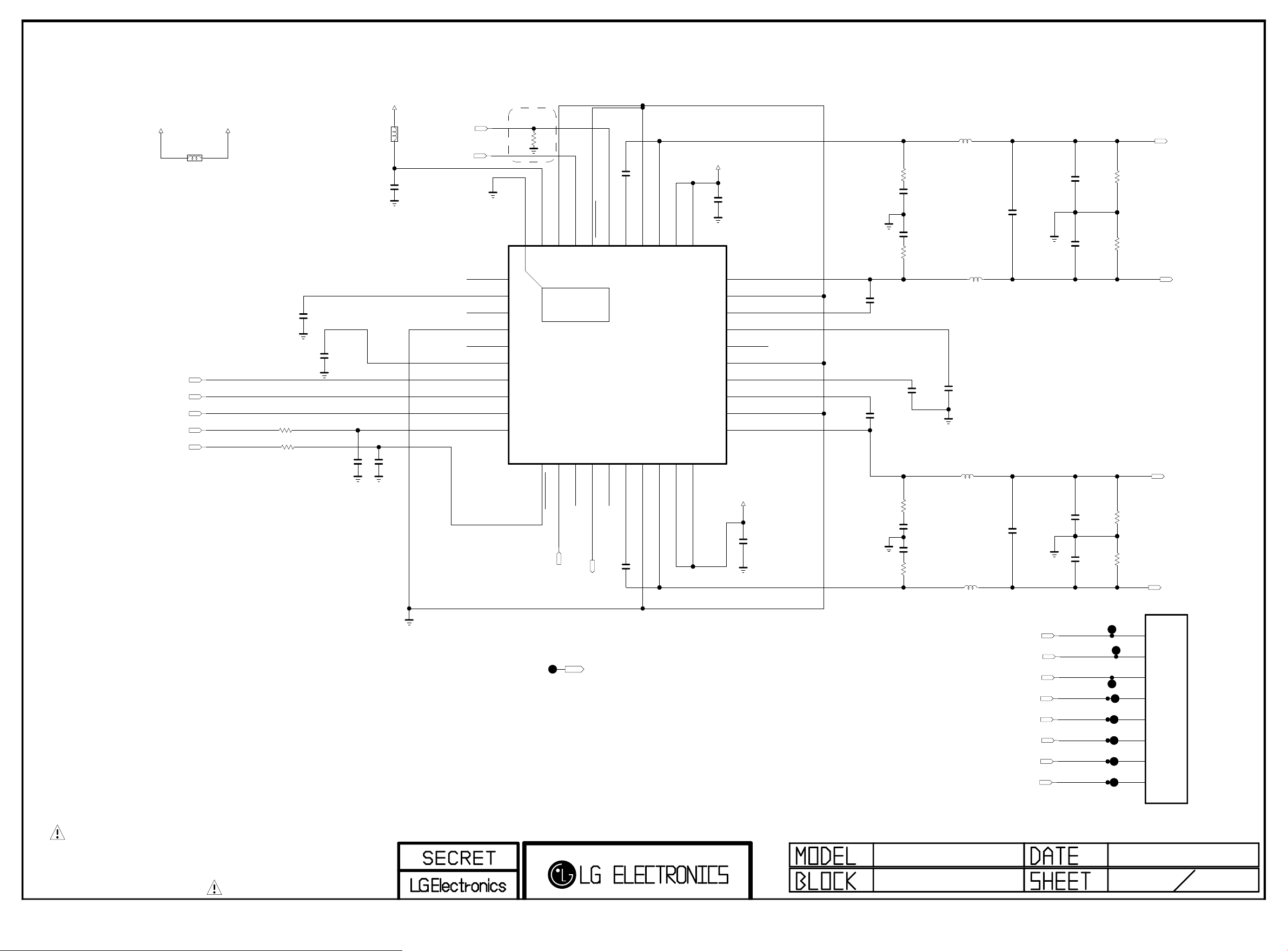
FRONT AMP(NTP7514)
Copyright ⓒ 2015 LG Electronics. Inc. All right reserved.
Only for training and service purposes
LGE Internal Use Only
+24V
AUD_LRCH
AUD_LRCK
AUD_SCK
I2C_SDA1
I2C_SCL1
+24V_TWEETER_AMP
L12001
UBW2012-121F
R12001
100
R12002
100
C12001
1uF
10V
L12002
BLM18PG121SN1D
C12002
1uF
10V
C12003
33pF
50V
+3.3V_NORMAL
C12005
0.1uF
16V
C12004
33pF
50V
AMP_RESET_N
AUD_MASTER_CLK
NC_1
VDD_PLL
NC_2
GND
NC_3
DVDD
SDATA
WCK
BCK
SDA
Near AMP
4.7K
R12003
TWEETER_RESET
GND_IO
VDD_IO
[EP]GND
40
1
2
THERMAL
3
4
5
6
7
8
9
10
11
SCL
FAULT
WOOFER_MUTE
RESET
AD
CLK_I
36
37
38
39
41
IC5601
NTP7514
0x54
DEV_NTP7514
12
13
14
15
MONITOR_0
MONITOR_1
MONITOR_2
C12007
22000pF
50V
I2S_TWEETER_AMP
50V
C12006
22000pF
PGND1A
BST1A
34
35
16
17
BST2B
PGND2B
PVDD1A
OUT1A
32
33
18
19
OUT2B
PVDD2B
+24V_TWEETER_AMP
C12008
10uF
35V
PVDD1B
31
30
29
28
27
26
25
24
23
22
21
20
+24V_TWEETER_AMP
PVDD2A
OUT1B
PGND1B
BST1B
VDR1
NC_4
AGND
VDR2
BST2A
PGND2A
OUT2A
C12009
10uF
35V
C12010
22000pF
50V
C12011
22000pF
50V
R12005
3.3
1/10W
C12012
390pF
50V
C12013
390pF
50V
R12006
3.3
1/10W
C12016
1uF
10V
R12007
3.3
1/10W
C12014
390pF
50V
C12015
390pF
50V
R12008
3.3
1/10W
L12003
10.0uH
NRS6045T100MMGK
L12006
10.0uH
NRS6045T100MMGK
C12017
1uF
10V
L12004
10.0uH
NRS6045T100MMGK
L12005
10.0uH
NRS6045T100MMGK
C12018
0.47uF
50V
C12019
0.47uF
50V
C12020
0.1uF
50V
C12021
0.1uF
50V
C12022
0.1uF
50V
C12023
0.1uF
50V
R12009
4.7K
R12010
4.7K
R12011
4.7K
R12012
4.7K
SPK_L+
SPK_L-
SPK_R+
SPK_R-
THE SYMBOL MARK OF THIS SCHEMETIC DIAGRAM INCORPORATES
SPECIAL FEATURES IMPORTANT FOR PROTECTION FROM X-RADIATION.
FIRE AND ELECTRICAL SHOCK HAZARDS, WHEN SERVICING IF IS
ESSENTIAL THAT ONLY MANUFACTURES SPECIFIED PARTS BE USED FOR
THE CRITICAL COMPONENTS IN THE SYMBOL MARK OF THE SCHEMETIC.
I2S_TWEETER_AMP
SPK_TW_L+
SPK_TW_L-
SPK_TW_R+
SPK_TW_R-
SPK_L+
SPK_L-
SPK_R+
SPK_R-
JP5611
JP5610
JP5609
JP5608
JP5604
JP5605
JP5606
JP5607
8
7
6
5
4
3
2
1
SMAW250-08
P11002
Page 62

Page 63
Contents of Standard Repair Process
Copyright ⓒ 2015 LG Electronics. Inc. All right reserved.
Only for training and service purposes
LGE Internal Use Only
No. Error symptom (High category) Error symptom (Mid category) Page Remarks
1
2 No video/No audio 2
3 Picture broken/ Freezing 3
4 Color error 4
5
6
7
8
9 Wrecked audio/discontinuation/noise 9
10
11
A. Video error
B. Power error
C. Audio error
No video/Normal audio 1
Vertical/Horizontal bar, residual image,
light spot, external device color error
No power 6
Off when on, off while viewing, power
auto on/off
No audio/Normal video 8
Remote control & Local switch checking
MR13 operating checking 11
10
5
7
12
13 Camera operating checking 13
14 External device recognition error 14
15 E. Noise Circuit noise, mechanical noise 15
16 F. Exterior error Exterior defect 16
D. Function error
First of all, Check whether there is SVC Bulletin in GCSC System for these model.
Wifi operating checking 12
Page 64
Standard Repair Process
Copyright ⓒ 2015 LG Electronics. Inc. All right reserved.
Only for training and service purposes
LGE Internal Use Only
Error
symptom
A. Video error
No video/ Normal audio
Established
date
Revised date
First of all, Check whether all of cables between board is inserted properly or not.
(Main B/D↔ Power B/D, EPI Cable,Speaker Cable,IR B/D Cable,,,)
☞A18 ☞A1
N
Y
Check OLED Light
On with naked eye
☞A18
Check Power Board 24V output
On
Normal
voltage
N
Repair Power
Board or parts
Y N Check Power
Board
24V, 12V,3.5V etc.
Replace Inverter
Y
or module
Normal
voltage
N
Repair Power
Board or parts
End
Replace T-con
Y
Board or module
And Adjust VCOM
No video
Normal audio
Normal
audio
Move to No
video/No audio
1/16
※Precaution
Always check & record S/W Version and White
Balance value before replacing the Main Board
☞A4 & A2
Replace Main Board
1
Re-enter White Balance value
Page 65
Standard Repair Process
Copyright ⓒ 2015 LG Electronics. Inc. All right reserved.
Only for training and service purposes
LGE Internal Use Only
Error
symptom
No Video/
No audio
☞A18
Check various
voltages of Power
Board ( 3.5V,12V,20V
or 24V…)
A. Video error
No video/ No audio
Normal
voltage?
Replace Power
Board and repair
parts
Y
N
Check and
replace
MAIN B/D
Established
date
Revised date
End
2/16
2
Page 66
Standard Repair Process
Copyright ⓒ 2015 LG Electronics. Inc. All right reserved.
Only for training and service purposes
LGE Internal Use Only
☞ A3
Check RF Signal level
Normal
Signal?
N
Check RF Cable
Connection
1. Reconnection
2. Install Booster
Normal
Picture?
Y
Close
Y
N
Error
symptom
A. Video error
Picture broken/ Freezing
. By using Digital signal level meter
. By using Diagnostics menu on OSD
( Setting→ Set up→ Manual Tuning → Check the Signal )
- Signal strength (Normal : over 50%)
- Signal Quality (Normal: over 50%)
Check whether other equipments have problem or not.
(By connecting RF Cable at other equipment)
→ DVD Player ,Set-Top-Box, Different maker TV etc`
☞ A4
Normal
Picture?
Contact with signal distributor
or broadcaster (Cable or Air)
Y
N
Check
S/W Version
Bulletin?
S/W Upgrade
SVC
Y
Normal
Picture?
Y
Established
date
Revised date
N
N
Check
Tuner soldering
N
Replace
Main B/D
3/16
Y
Close
Close
3
Page 67
Standard Repair Process
Copyright ⓒ 2015 LG Electronics. Inc. All right reserved.
Only for training and service purposes
LGE Internal Use Only
☞A6
Check color by input
-External Input
-COMPONENT
-AV
-HDMI
☞A8
Check Test pattern
Error
symptom
Color
error?
N
Check error
color input
mode
A. Video error
☞ A7
※ Check
and replace
Y
Link Cable
(EPI) and
contact
condition
External Input/
Component
error
Color error
Color
error?
N
Check
external
device and
cable
Y
Replace Main B/D
Established
date
Revised date
External device
/Cable
normal
N
Color
error?
End
Y
4/16
Y
Replace module
N
Replace Main B/D
HDMI
error
Check external
device and
cable
4
Request repair
for external
device/cable
N
External device
/Cable
normal
Y
Replace Main B/D
Page 68
Standard Repair Process
Copyright ⓒ 2015 LG Electronics. Inc. All right reserved.
Only for training and service purposes
LGE Internal Use Only
Error
symptom
Vertical / Horizontal bar, residual image,
A. Video error
light spot, external device color error
Vertical/Horizontal bar, residual image, light spot
☞A6
Check color condition by input
-External Input
-Component
-HDMI
☞A8
Check Test pattern
Screen
normal?
N
Replace
module
Check external
Y
device
connection
condition
Normal?
N
Request repair
for external
device
External device screen error-Color error
Check screen
condition by input
Check S/W Version
Check
version
Y
S/W Upgrade
N
-External Input
-Component
-HDMI/DVI
Component
☞ A7
Check and
Y
replace Link
Cable
External
Input
error
error
Established
date
Revised date
Y
N
Replace Main B/D
(adjust VCOM)
For LGD panel
Replace Main B/D
Screen
normal?
End
For other panel
Connect other external
device and cable
(Check normal operation of
External Input, Component,
RGB and HDMI/DVI by
connecting Jig, pattern
Generator ,Set-top Box etc.
Screen
N
normal?
Y
Request repair for
external device
5/16
Replace
Module
N
Screen
normal?
Y
End
Replace
Main B/D
Normal
screen?
End
N
Y
5
HDMI/
DVI
Connect other external
device and cable
(Check normal operation of
External Input, Component,
RGB and HDMI/DVI by
connecting Jig, pattern
Generator ,Set-top Box etc.
Y
Screen
normal?
N
Replace
Main B/D
Page 69
Standard Repair Process
Copyright ⓒ 2015 LG Electronics. Inc. All right reserved.
Only for training and service purposes
LGE Internal Use Only
symptom
☞A17
Check
Logo LED
. Stand-By: Red or Turn Off
. Operating: Turn Off
Power LED
Check Power cord
was inserted properly
Error
On?
N
Normal?
Y
Close
Y
N
※
Check ST-BY 3.5V
☞A18
B. Power error
No power
DC Power on
by pressing Power Key
On Remote control
Normal
voltage?
Y
Y
N
Established
date
Revised date
☞A18
Y
N
Check Power
On ‘”High”
Replace Main B/D
Normal
operation?
☞A18
Measure voltage of each output of Power B/D
N
Y
Replace Main B/D
Normal
voltage?
Replace Power B/D
OK?
Y
6/16
Replace
Power
B/D
Replace Power
B/D
6
Page 70
Standard Repair Process
Copyright ⓒ 2015 LG Electronics. Inc. All right reserved.
Only for training and service purposes
LGE Internal Use Only
Check outlet
Check A/C cord
Check for all 3- phase
power out
Error
symptom
Error?
Y
Fix A/C cord & Outlet
and check each 3
phase out
B. Power error
Off when on, off while viewing, power auto on/off
☞A19
N
Check Power Off
Mode
☞A18
(If Power Off mode
is not displayed)
Check Power B/D
voltage
※ Caution
Check and fix exterior
of Power B/D Part
Abnormal
Abnormal
Established
date
Revised date
CPU
1
Normal
voltage?
Replace Power B/D
Replace Main B/D
Y
N
Replace Power B/D
Replace Main B/D
Normal?
N
7/16
Y
End
* Please refer to the all cases which
can be displayed on power off mode.
Status Power off List Explanation
"POWEROFF_REMOTEKEY" Power off by REMOTE CONTROL
"POWEROFF_OFFTIMER" Power off by OFF TIMER
"POWEROFF_SLEEPTIMER" Power off by SLEEP TIMER
"POWEROFF_INSTOP" Power off by INSTOP KEY
"POWEROFF_AUTOOFF" Power off by AUTO OFF
Normal
Abnormal
"POWEROFF_ONTIMER" Power off by ON TIMER
"POWEROFF_20V_DET" Power off by AC OFF
"POWEROFF_RESREC" Power off by Reservated Record
"POWEROFF_RECEND" Power off by End of Recording
"POWEROFF_SWDOWN" Power off by S/W Download
"POWEROFF_UNKNOWN" Power off by unknown status except listed case
"POWEROFF_ABNORMAL1" Power off by abnormal status except CPU trouble
"POWEROFF_CPUABNORMAL" Power off by CPU Abnormal
7
Page 71
Standard Repair Process
Copyright ⓒ 2015 LG Electronics. Inc. All right reserved.
Only for training and service purposes
LGE Internal Use Only
No audio
Screen normal
Error
C. Audio error
symptom
No audio/ Normal video
☞A20 ☞A21+A18
Check user
menu >
Speaker off
Off
Y
Cancel OFF
Check audio B+ 24
N
of Power Board
Established
date
Revised date
Normal
voltage
Replace Power Board and repair parts
Y
N
8/16
Check
Speaker
disconnection
Disconnection
Y
Replace Speaker
8
N
Replace MAIN Board
End
Page 72
Standard Repair Process
Copyright ⓒ 2015 LG Electronics. Inc. All right reserved.
Only for training and service purposes
LGE Internal Use Only
Check input
signal
-RF
-External Input
signal
Error
symptom
C. Audio error
Wrecked audio/ discontinuation/noise
Established
date
Revised date
→ abnormal audio/discontinuation/noise is same after “Check input signal” compared to No audio
☞A21+A18
Check audio
B+ Voltage (24V)
Y
Normal
voltage?
N
Replace Power B/D
Replace Main B/D
N
Y
Signal
normal?
N
Y
(When RF signal is not
received)
Request repair to external
cable/ANT provider
(In case of
External Input
signal error)
Check and fix
external device
Wrecked audio/
Discontinuation/
Noise for
all audio
Wrecked audio/
Discontinuation/
Noise only
for D-TV
Wrecked audio/
Discontinuation/
Noise only
for Analog
Wrecked audio/
Discontinuation/
Noise only
for External Input
Check and replace
speaker and
connector
Replace Main B/D
Connect and check
other external
device
Normal
audio?
9/16
End
Check and fix external device
9
Page 73
Standard Repair Process
Copyright ⓒ 2015 LG Electronics. Inc. All right reserved.
Only for training and service purposes
LGE Internal Use Only
Error
symptom
D. Function error
Remote control & Local switch checking
1. Remote control(R/C) operating error
☞A22
Check R/C itself
Operation
Check R/C Operating
When turn off light
in room
If R/C operate,
Explain the customer
cause is interference
from light in room.
operating?
Normal
Y
N
Check & Replace
Baterry of R/C
Normal
operating?
Replace R/C
Check & Repair
Cable connection
Connector solder
Y
Close
N
Normal
operating?
Y
Close
☞A22
N
On Main B/D
Established
date
Revised date
Check B+
3.5V
Normal
Voltage?
N
☞A18
Check 3.5v on Power B/D
Replace Power B/D or
Replace Main B/D
(Power B/D don’t have problem)
☞A22
Y
Check IR
Output signal
10/16
Replace
Main B/D
Normal
Signal?
N
Repair/Replace
IR B/D
Y
10
Page 74
Standard Repair Process
Copyright ⓒ 2015 LG Electronics. Inc. All right reserved.
Only for training and service purposes
LGE Internal Use Only
Error
symptom
D. Function error
MR13/P operating checking
2. MR13/P (Magic Remote control) operating error
☞A4
Check the
INSTART menu
RF Receiver ver
is “00.00”?
☞A23
Check & Repair
connection
Y
RF assy
☞A4
RF Receiver ver
is “00.00”?
Y
N
Check MR13/P
itself Operation
N
Close
Normal
operating?
Check & Replace
Battery of MR13/P
Normal
operating?
Replace
N
N
MR13
Y
Y
Press the
wheel
Close
Established
date
Revised date
Is show ok
message?
Y
Close
Is show ok
message?
Close
Y
Turn off/on the
N
set and press
the wheel
N
11/16
Press the back
key about 5sec
Down load the Firmware
* INSTART MENU02.11
Remote control Test3.
Firmware download
•If you conduct the loop at 3times, change the
MR13/P.
11
Page 75
Standard Repair Process
Copyright ⓒ 2015 LG Electronics. Inc. All right reserved.
Only for training and service purposes
LGE Internal Use Only
Error
symptom
3.Wifi operating error
☞A4
Check the
INSTART menu
Wi-Fi Mac value
is “NG”?
☞A24
Check & Repair
Y
Wifi cable
connection
☞A4
Wi-Fi Mac value
is “NG”?
D. Function error
Wifi operating checking
☞A24
N
Check the Wifi wafer
N
Close
1pin
Established
Revised date
Normal
Voltage?
Y
Close
date
N
12/16
Replace
Main B/D
Change the Wifi
Y
assy
12
Page 76
Standard Repair Process
Copyright ⓒ 2015 LG Electronics. Inc. All right reserved.
Only for training and service purposes
LGE Internal Use Only
Error
symptom
4.Camera operating error
☞A4
Check the
INSTART menu
☞A25
Check & Repair
Camera cable
☞A4
D. Function error
Camera Ver.
is “NG”?
Y
connection
Camera Ver.
is “NG”?
Camera operating checking
☞A25
N
Check the Camera wafer
P4200 2pin
N
Close
Established
Revised date
Normal
Voltage?
Y
Close
date
N
13/16
Replace
Camera B/D
Y
Change the
Camera assy
13
Page 77
Standard Repair Process
Copyright ⓒ 2015 LG Electronics. Inc. All right reserved.
Only for training and service purposes
LGE Internal Use Only
Check
input
signal
Error
symptom
Y
Signal
input?
N
Check and fix
external device/cable
D. Function error
External device recognition error
Check technical
information
- Fix information
- S/W Version
Technical
information?
Fix in
accordance
with technical
information
Y
External Input and
N
Component
Recognition error
HDMI/
DVI, Optical
Recognition error
Established
date
Revised date
14/16
Replace Main B/D
Replace Main B/D
14
Page 78
Standard Repair Process
Copyright ⓒ 2015 LG Electronics. Inc. All right reserved.
Only for training and service purposes
LGE Internal Use Only
Identify
nose
type
Error
symptom
Circuit
noise
Mechanical
noise
Circuit noise, mechanical noise
Check
location of
noise
Check location of
noise
E. Noise
※ Mechanical noise is a natural
phenomenon, and apply the 1st level
description. When the customer does not
agree, apply the process by stage.
※ Describe the basis of the description
in “Part related to nose” in the Owner’s
Manual.
Replace PSU
OR
Established
date
Revised date
※ When the nose is severe, replace the module
(For models with fix information, upgrade the
S/W or provide the description)
※ If there is a “Tak Tak” noise from the
cabinet, refer to the KMS fix information and
then proceed as shown in the solution manual
(For models without any fix information,
provide the description)
15/16
15
Page 79
Standard Repair Process
Copyright ⓒ 2015 LG Electronics. Inc. All right reserved.
Only for training and service purposes
LGE Internal Use Only
Error
symptom
Zoom part with
exterior damage
F. Exterior defect
Module
damage
Cabinet
damage
Remote
controller
damage
Exterior defect
Replace module
Replace cabinet
Replace Remote control
Established
date
Revised date
16/16
Stand
dent
Replace stand
16
Page 80
Contents of OLED TV Standard Repair Process Detail Technical Manual
Copyright ⓒ 2015 LG Electronics. Inc. All right reserved.
Only for training and service purposes
LGE Internal Use Only
No. Error symptom Content Page Remarks
1
A. Video error_ No video/Normal
audio
2 Check White Balance value A2
4
A. Video error_ video error /Video
lag/stop
5 LCD-TV Version checking method A4
6 Tuner Checking Part A5
A. Video error _Vertical/Horizontal bar,
7
residual image, light spot
8
A. Video error_ Color error
9 Adjustment Test pattern - ADJ Key A8
10
11 Exchange Main Board (2) A-2/2
<Appendix>
12 Exchange Power Board (PSU) A-3/5
Defected Type caused by T-Con/
Inverter/ Module
13 Exchange Module (1) A-4/5
Check vby1 lock LED and Module supply
voltage
TUNER input signal strength checking
method
connection diagram A6
Check Link Cable (EPI) reconnection
condition
Exchange Main Board (1) A-1/2
A1
A3
A7
14 Exchange Module (2) A-5/5
Continue to the next page
Page 81
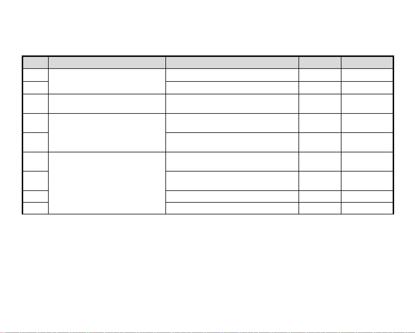
Contents of Standard Repair Process Detail Technical Manual
Copyright ⓒ 2015 LG Electronics. Inc. All right reserved.
Only for training and service purposes
LGE Internal Use Only
Continued from previous page
No. Error symptom Content Page Remarks
16
B. Power error_ No power
17 Check power input Voltage & ST-BY 3.5V A18
18
19
20
21
22
23 Wifi operation checking method A24
24 Camera operation checking method A25
B. Power error_Off when on, off
while viewing
C. Audio error_ No audio/Normal
video
D. Function error
Check front display LED A17
POWER OFF MODE checking method A19
Checking method in menu when there is
no audio
Voltage and speaker checking method
when there is no audio
Remote control operation checking
method
Motion Remote operation checking
method
A20
A21
A22
A23
Page 82
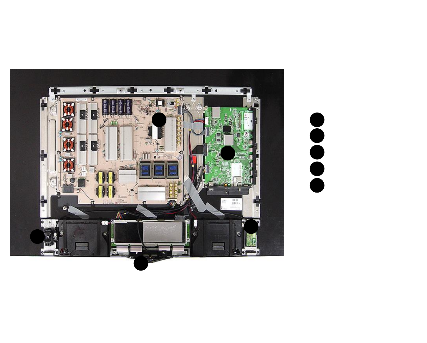
Interconnection - 1
Copyright ⓒ 2015 LG Electronics. Inc. All right reserved.
Only for training and service purposes
LGE Internal Use Only
[PCBs]
5
4
2
1
3
1
Main PCB
2
PSU
3
WIFI + BT Combo ASSY
4
IR / Logo PCB
5
Joystick
Page 83
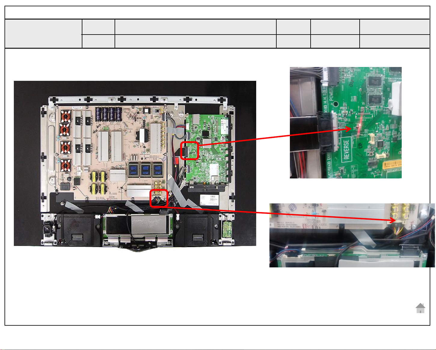
Standard Repair Process Detail Technical Manual
Copyright ⓒ 2015 LG Electronics. Inc. All right reserved.
Only for training and service purposes
LGE Internal Use Only
Error
symptom
Content
A. Video error_No video/Normal audio
CHECK the vby1 and Module supply voltage
Established
date
Revised
date
A1
‘Red LED signal ‘ means video output is good
Check the Module supply voltage ’24V’
A1
Page 84
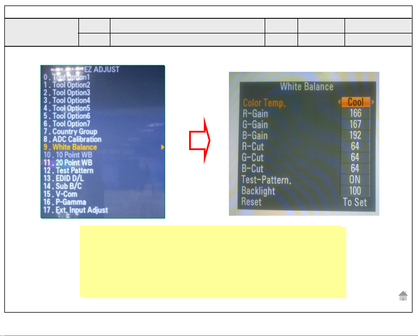
Standard Repair Process Detail Technical Manual
Copyright ⓒ 2015 LG Electronics. Inc. All right reserved.
Only for training and service purposes
LGE Internal Use Only
Error
symptom
Content
A. Video error_No video/Normal audio
Check White Balance value
Established
date
Revised
date
A2
Entry method
Entry method
1. Press the ADJ button on the Remote control for adjustment.
1. Press the ADJ button on the Remote control for adjustment.
2. Enter into White Balance of item 6.
2. Enter into White Balance of item 9.
3. After recording the R, G, B (GAIN, Cut) value of Color Temp
3. After recording the R, G, B (GAIN, Cut) value of Color Temp
(Cool/Medium/Warm), re-enter the value after replacing the MAIN BOARD.
(Cool/Medium/Warm), re-enter the value after replacing the MAIN BOARD.
A2
Page 85
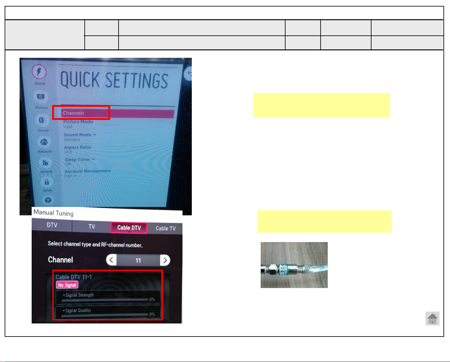
Standard Repair Process Detail Technical Manual
Copyright ⓒ 2015 LG Electronics. Inc. All right reserved.
Only for training and service purposes
LGE Internal Use Only
Error
symptom
Content
A. Video error_Video error, video lag/stop
TUNER input signal strength checking method
Established
date
Revised
date
Settings Channel Manual Tuning
select channel
A3
When the signal is strong, use the
attenuator (-10dB, -15dB, -20dB etc.)
A3
Page 86
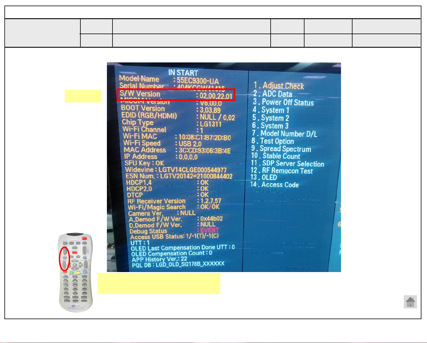
Standard Repair Process Detail Technical Manual
Copyright ⓒ 2015 LG Electronics. Inc. All right reserved.
Only for training and service purposes
LGE Internal Use Only
Error
symptom
Content
Version
A. Video error_Video error, video lag/stop
OLED TV Version checking method
1. Checking method for Remote control for adjustment
Established
date
Revised
date
A4
Press the IN-START with the
Remote control for adjustment
A4
Page 87
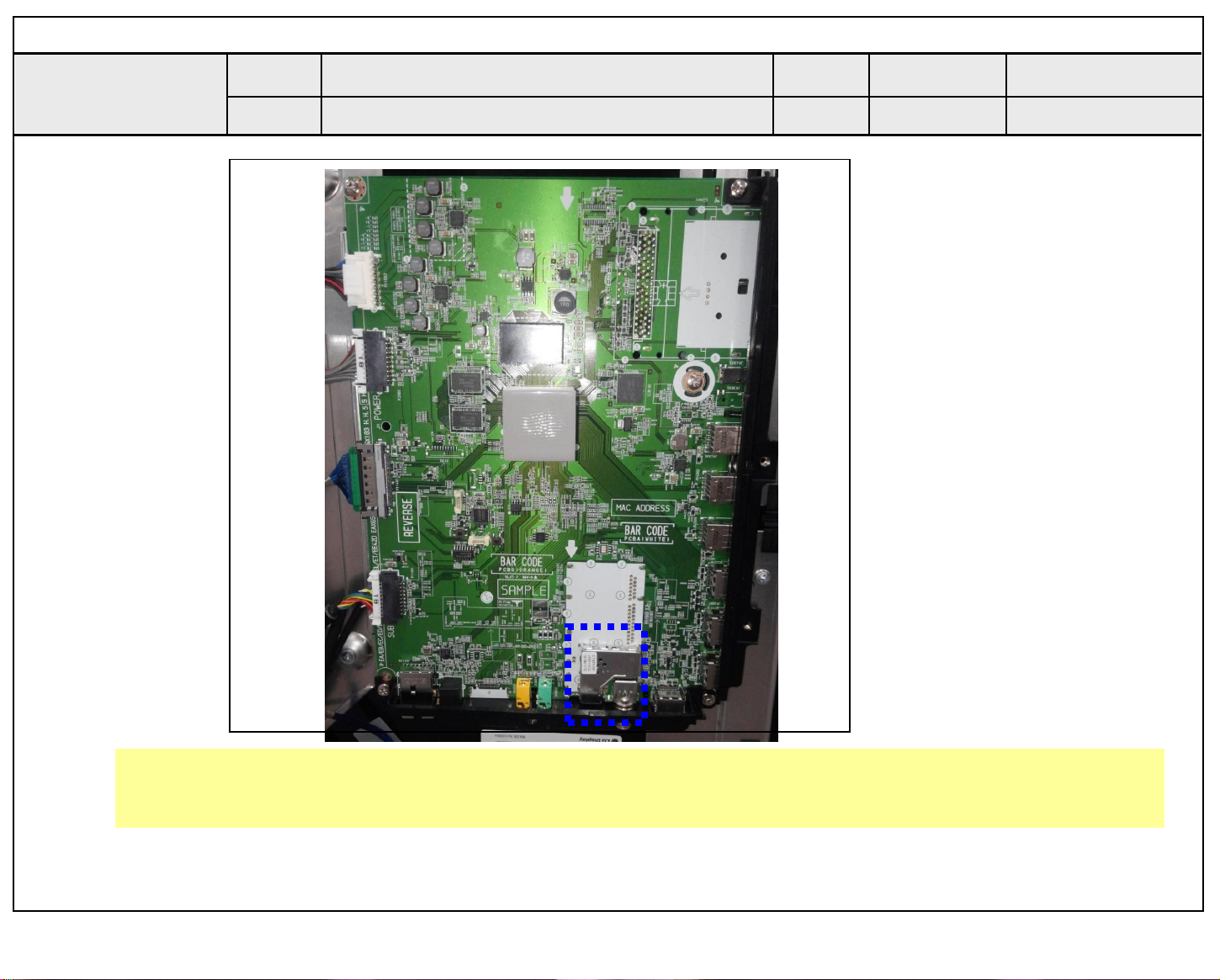
Standard Repair Process Detail Technical Manual
Copyright ⓒ 2015 LG Electronics. Inc. All right reserved.
Only for training and service purposes
LGE Internal Use Only
Error
symptom
Content
A. Video error_Video error, video lag/stop
TUNER checking part
Established
date
Revised
date
A5
Checking method:
1. Check the signal strength or check whether the screen is normal when the external device is connected.
2. After measuring each voltage from power supply, finally replace the MAIN BOARD.
A5
Page 88
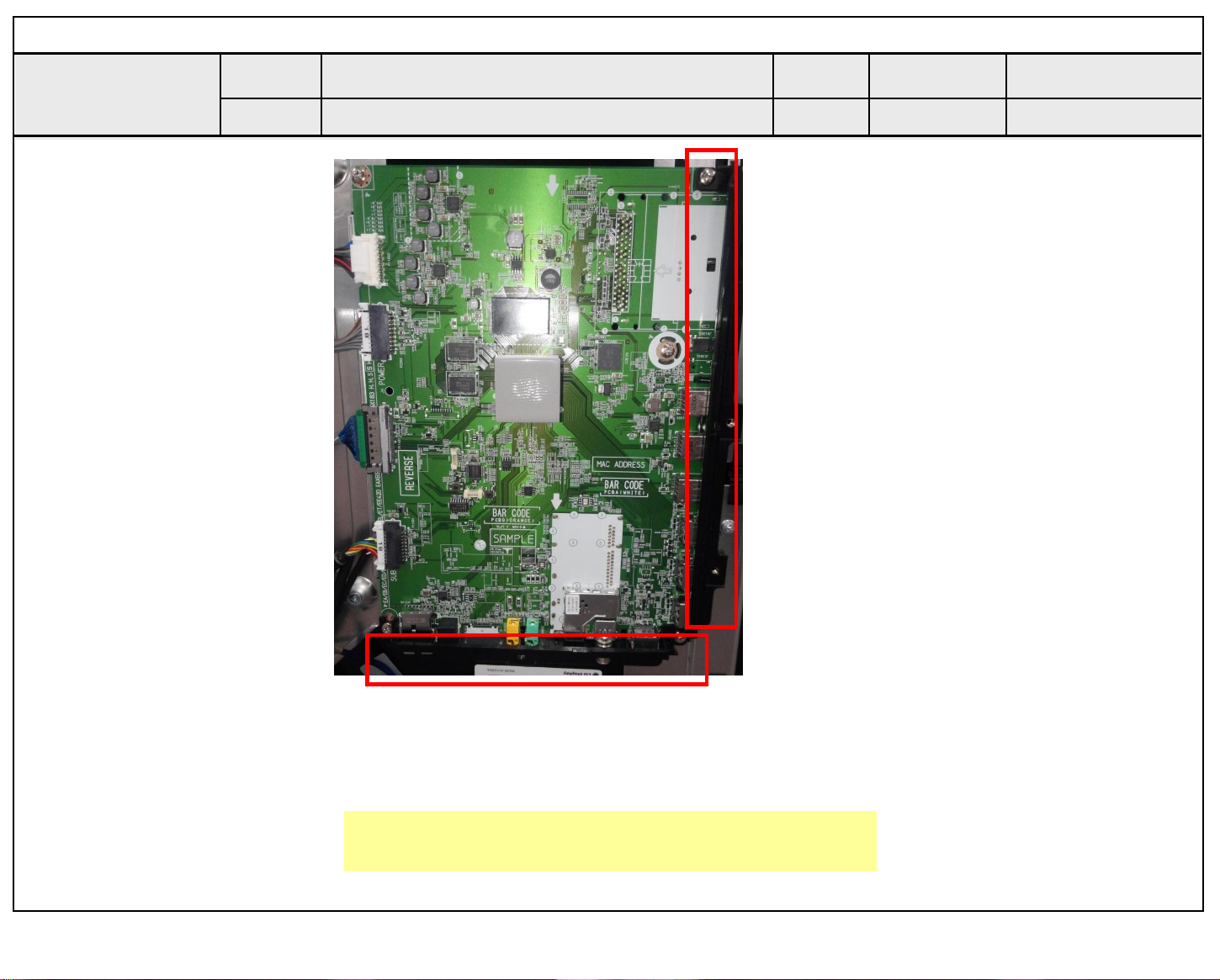
Standard Repair Process Detail Technical Manual
Copyright ⓒ 2015 LG Electronics. Inc. All right reserved.
Only for training and service purposes
LGE Internal Use Only
Error
symptom
Content
A. Video error _Vertical/Horizontal bar,
residual image, light spot
connection diagram (1)
Established
date
Revised
date
A6
As the part connecting to the external input, check
the screen condition by signal
A6
Page 89
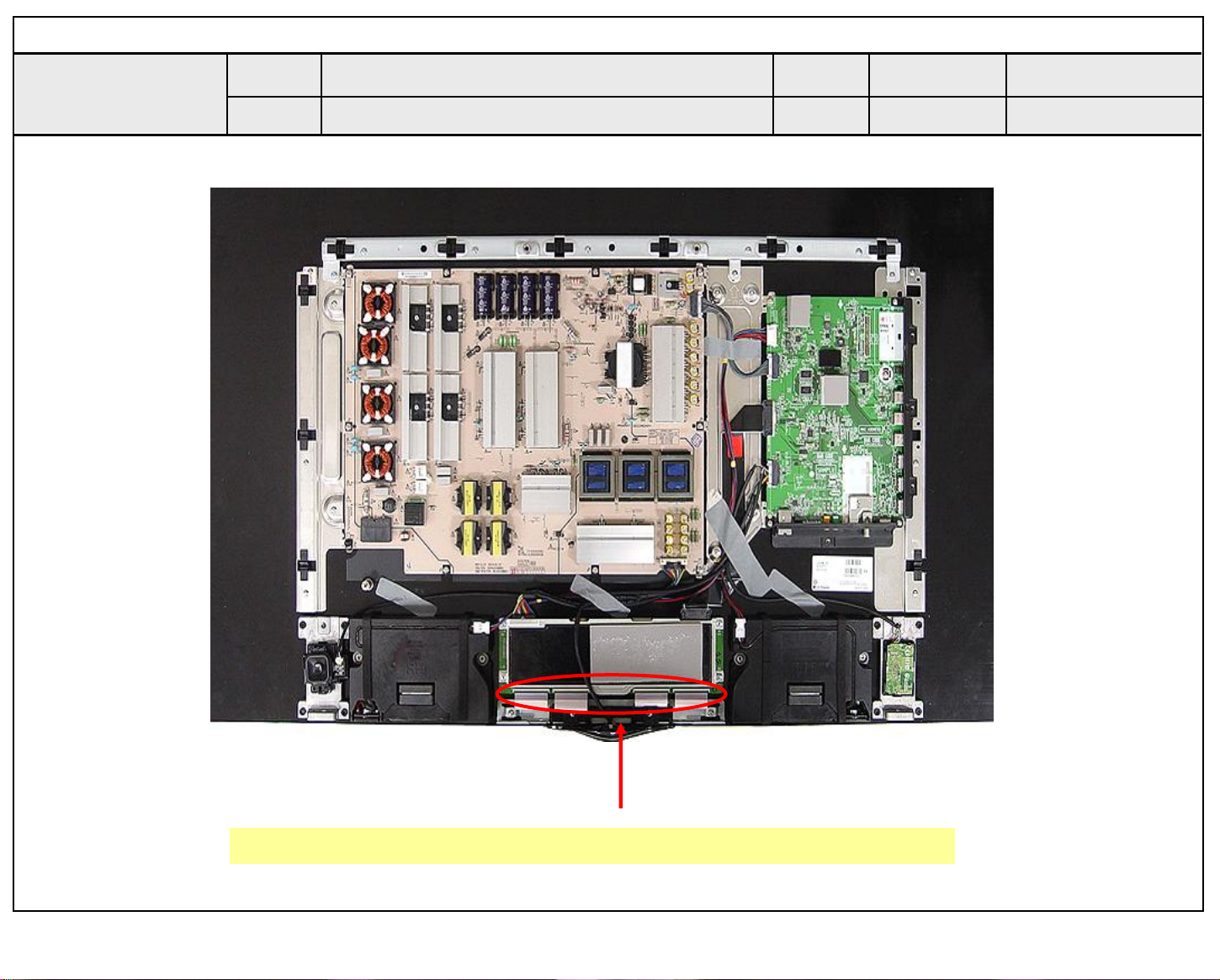
Standard Repair Process Detail Technical Manual
Copyright ⓒ 2015 LG Electronics. Inc. All right reserved.
Only for training and service purposes
LGE Internal Use Only
Error
symptom
Content
Check Link Cable (EPI) reconnection condition
A. Video error_Color error
Established
date
Revised
date
A7
Check the contact condition of the Link Cable, especially dust or mis insertion.
A7
Page 90
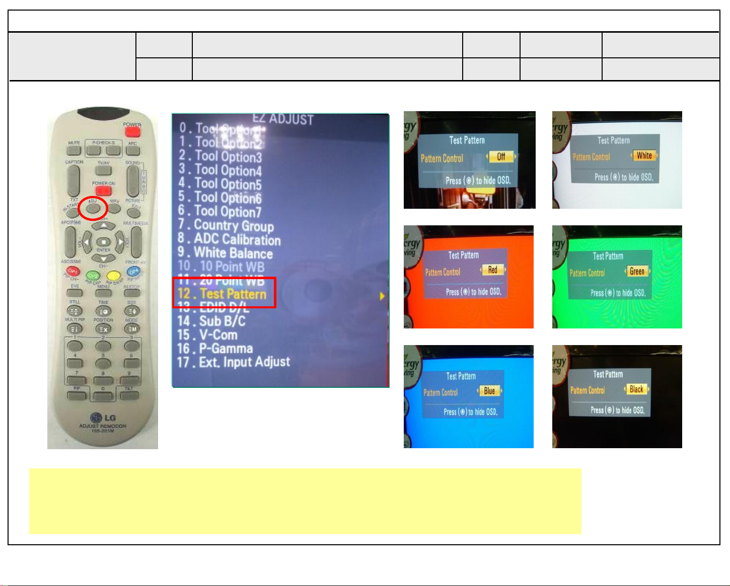
Standard Repair Process Detail Technical Manual
Copyright ⓒ 2015 LG Electronics. Inc. All right reserved.
Only for training and service purposes
LGE Internal Use Only
Error
symptom
Content
A. Video error_Color error
Adjustment Test pattern - ADJ Key
Established
date
Revised
date
A8
You can view 6 types of patterns using the ADJ Key
Checking item : 1. Defective pixel 2. image stickying 3. MODULE error (ADD-BAR,SCAN BAR..)
4.Video error (Classification of MODULE or Main-B/D!)
A8
Page 91
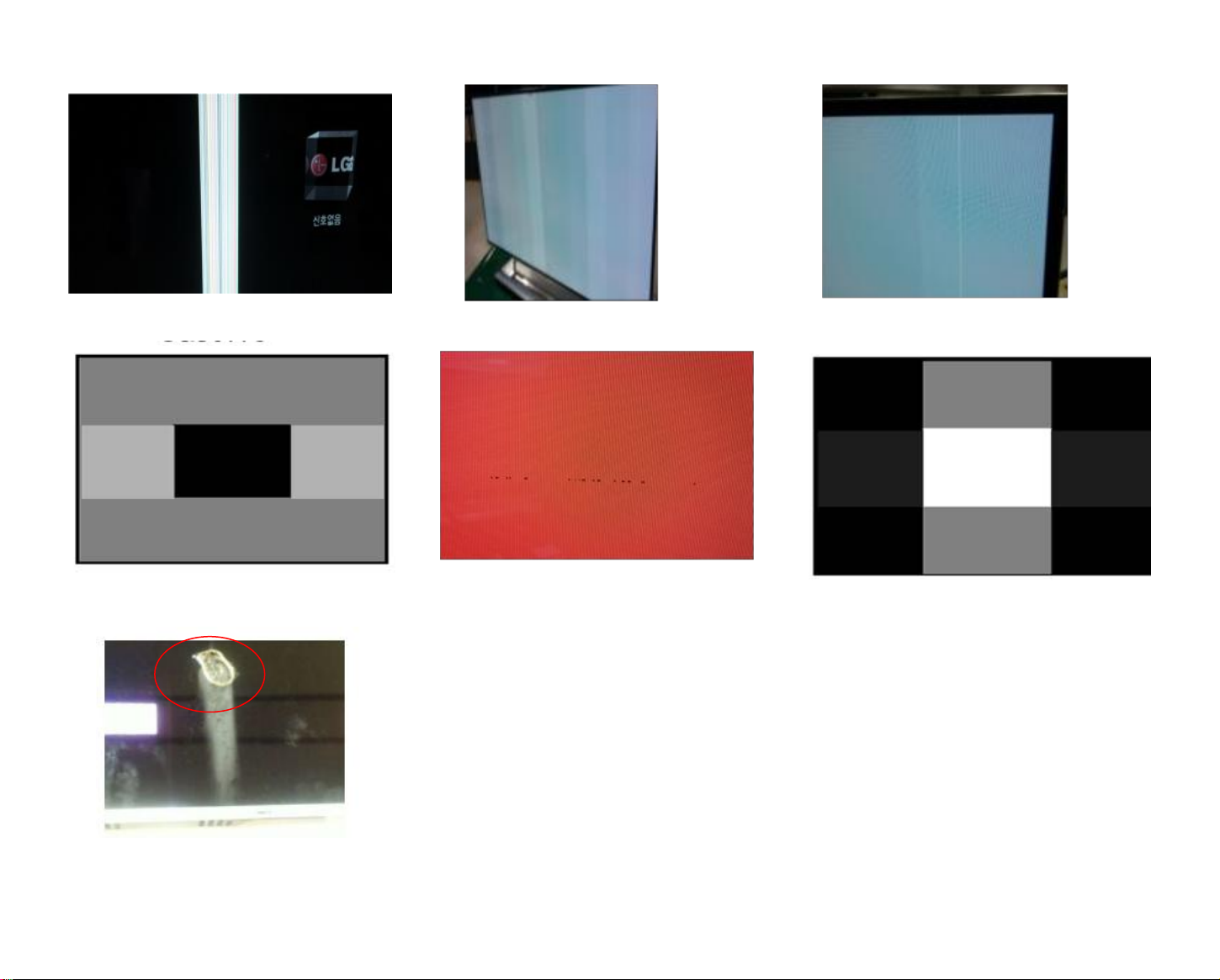
Appendix : Exchange the Module (1)
Copyright ⓒ 2015 LG Electronics. Inc. All right reserved.
Only for training and service purposes
LGE Internal Use Only
Vertical bar
Crosstalk
Brightness difference
Press damage
Line Dim
Crosstalk
Un-repairable Cases
In this case please exchange the module.
Burnt
A-1/2
Page 92
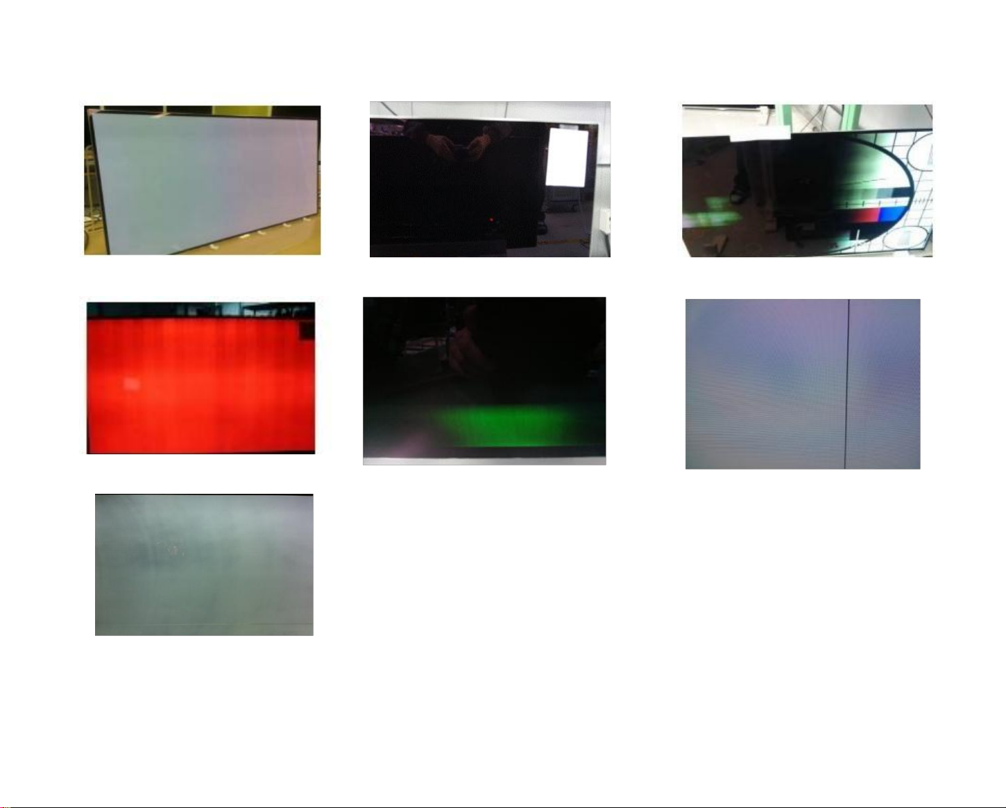
Appendix : Exchange the Module (2)
Copyright ⓒ 2015 LG Electronics. Inc. All right reserved.
Only for training and service purposes
LGE Internal Use Only
Angle view Color difference Brightness dot noise Half dead
Brightness difference
Mura
Green Noise on power on/off time
Line Defect
Un-repairable Cases
In this case please exchange the module.
A-2/2
Page 93
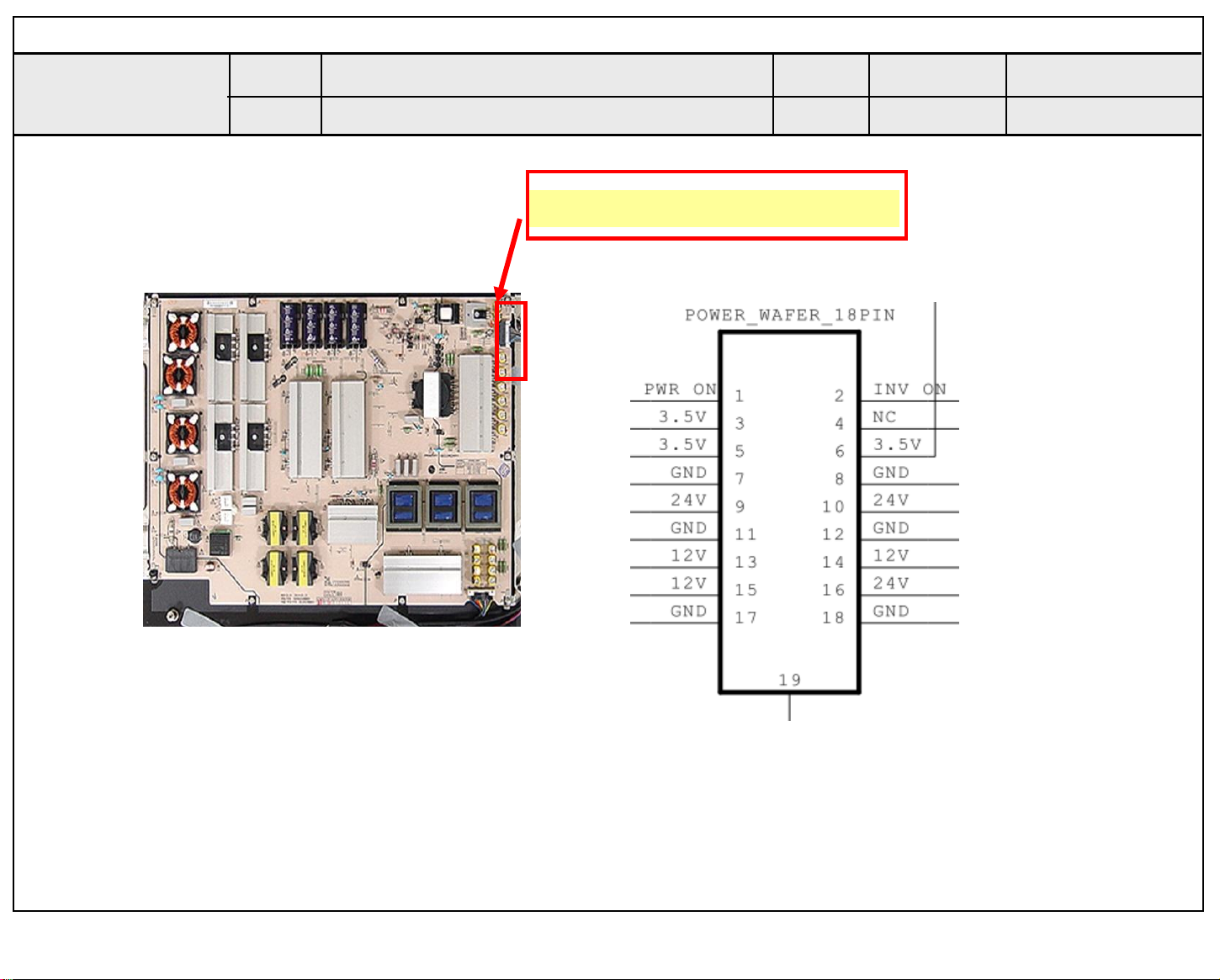
Standard Repair Process Detail Technical Manual
Copyright ⓒ 2015 LG Electronics. Inc. All right reserved.
Only for training and service purposes
LGE Internal Use Only
Error
symptom
Content
B. Power error _No power
Check power input voltage and ST-BY 3.5V
Check the DC 24V, 12V, 3.5V.
Established
date
Revised
date
A18
A18
Page 94
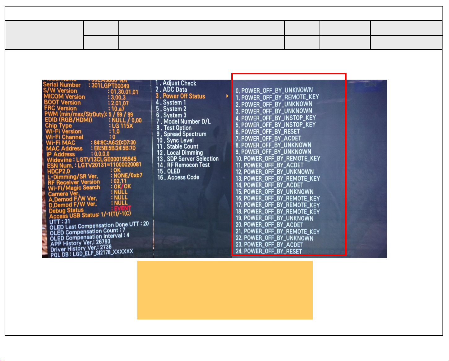
Standard Repair Process Detail Technical Manual
Copyright ⓒ 2015 LG Electronics. Inc. All right reserved.
Only for training and service purposes
LGE Internal Use Only
Error
symptom
Content
B. Power error _Off when on, off whiling viewing
POWER OFF MODE checking method
Established
date
Revised
date
A19
Entry method
1. Press the IN-START button of the Remote
control for adjustment
2. Check the entry into adjustment item 3
A19
Page 95
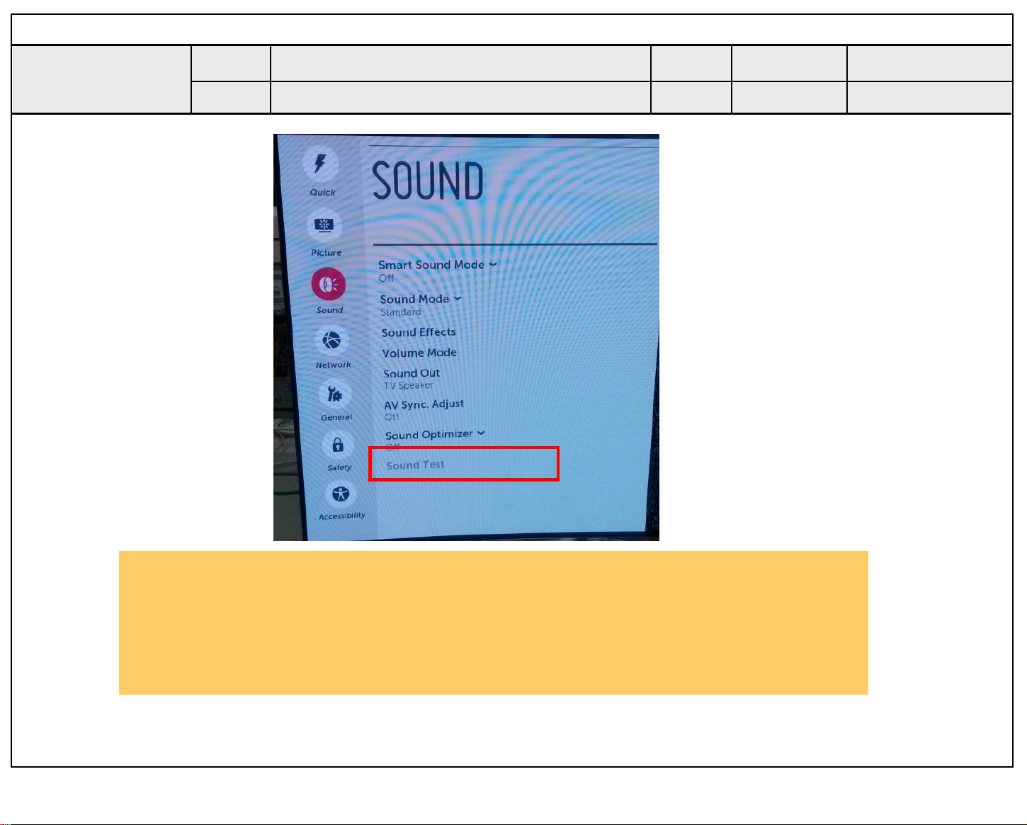
Standard Repair Process Detail Technical Manual
Copyright ⓒ 2015 LG Electronics. Inc. All right reserved.
Only for training and service purposes
LGE Internal Use Only
Error
symptom
Content
C. Audio error_No audio/Normal video
Checking method in menu when there is no audio
Established
date
Revised
date
A20
Checking method
1. Press the Setting button on the Remote control
2. Select the Sound function of the Menu
3. Select the Sound Setting
4. Select TV Speaker
A20
Page 96
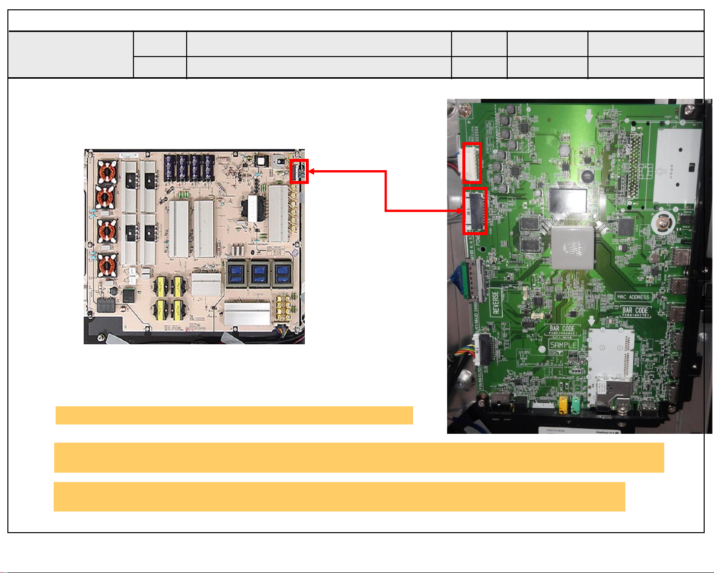
Standard Repair Process Detail Technical Manual
Copyright ⓒ 2015 LG Electronics. Inc. All right reserved.
Only for training and service purposes
LGE Internal Use Only
Error
symptom
Content
C. Audio error_No audio/Normal video
Voltage and speaker checking method
when there is no audio
②
①
Established
Revised
③
date
date
A21
③
Checking order when there is no audio
① Check the contact condition of or 24V connector of Main Board
② Measure the 24V input voltage supplied from Power Board
(If there is no input voltage, remove and check the connector)
③ Connect the tester RX1 to the speaker terminal and if you hear the Chik Chik sound when you touch the
GND and output terminal, the speaker is normal.
A21
Page 97
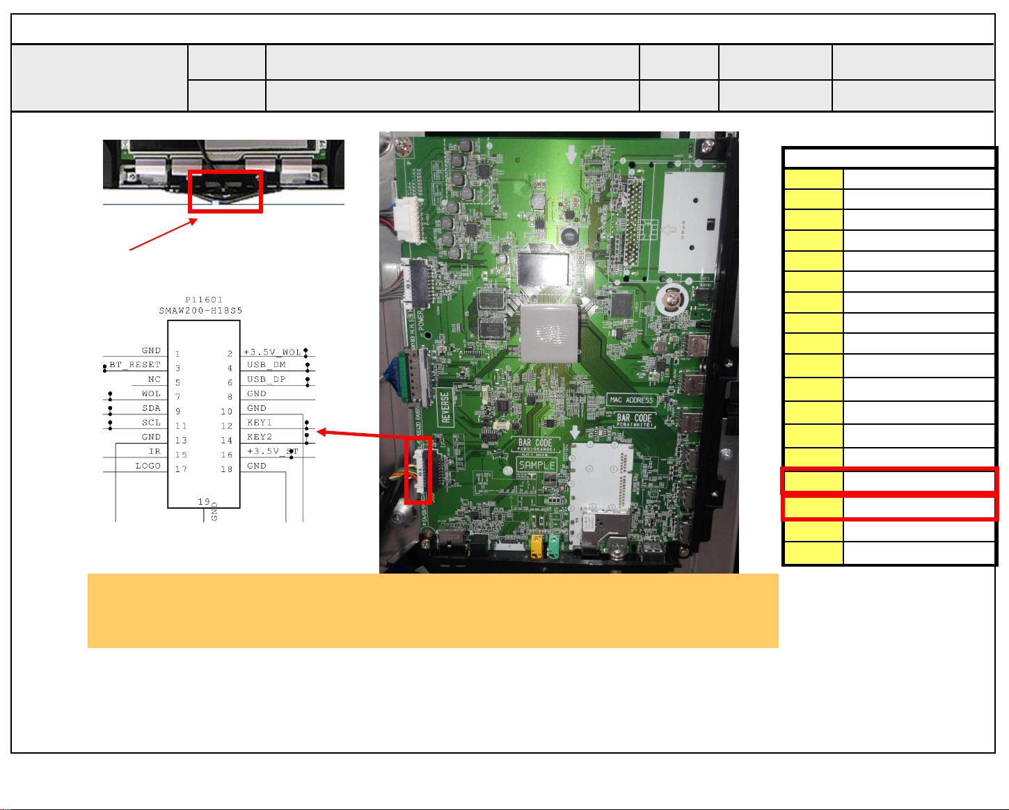
Standard Repair Process Detail Technical Manual
Copyright ⓒ 2015 LG Electronics. Inc. All right reserved.
Only for training and service purposes
LGE Internal Use Only
①
Error
symptom
Content
Remote control operation checking method
D. Function error
②
Established
date
Revised
date
A22
③ P4000
1
2
3
4
5
6
7 WIFI_POWER_ON
8 GND
9 EYE_SDA
10 GND
11 EYE_SCL
12 KEY1
13 GND
14 KEY2
15 IR
16 +3.5V_ST
17 LED_R
18 GND
+3.5V_WOL
BT_RESET
WIFI_DM
WIFI_DP
GND
NC
Checking order
1, 2. Check Touch cable condition between IR & Main board.
3. Check the st-by 3.5V on the terminal 16.
A22
Page 98
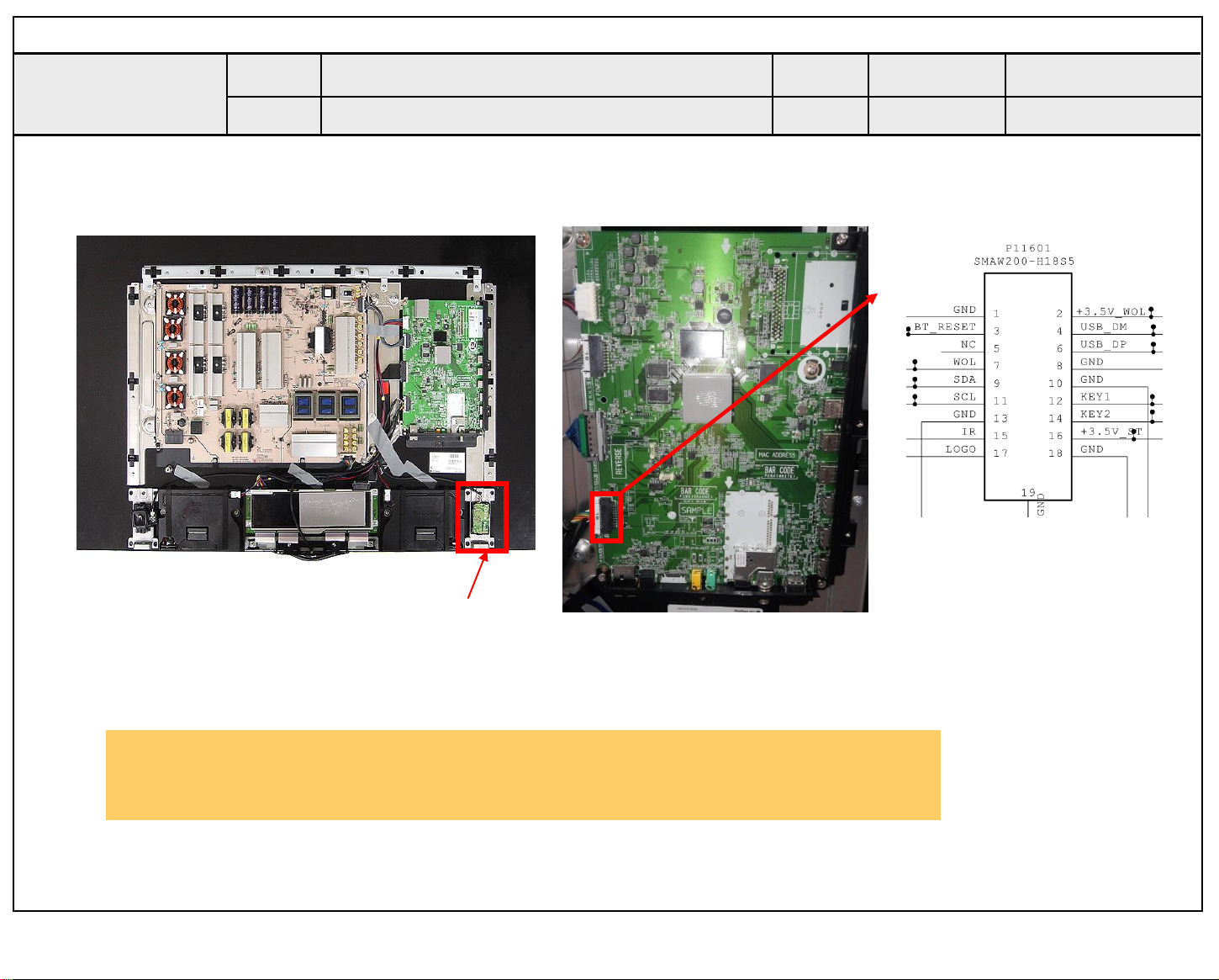
Standard Repair Process Detail Technical Manual
Copyright ⓒ 2015 LG Electronics. Inc. All right reserved.
Only for training and service purposes
LGE Internal Use Only
Error
symptom
Content
Motion Remote operation checking method
D. Function error
Established
date
Revised
date
A23
③
Checking order
1, 2. Check Motion cable condition between Motion assy & Main board.
3. Check the 3.5V_WOL on the terminal 2.
②
①
Wifi + BT Combo
A23
Page 99
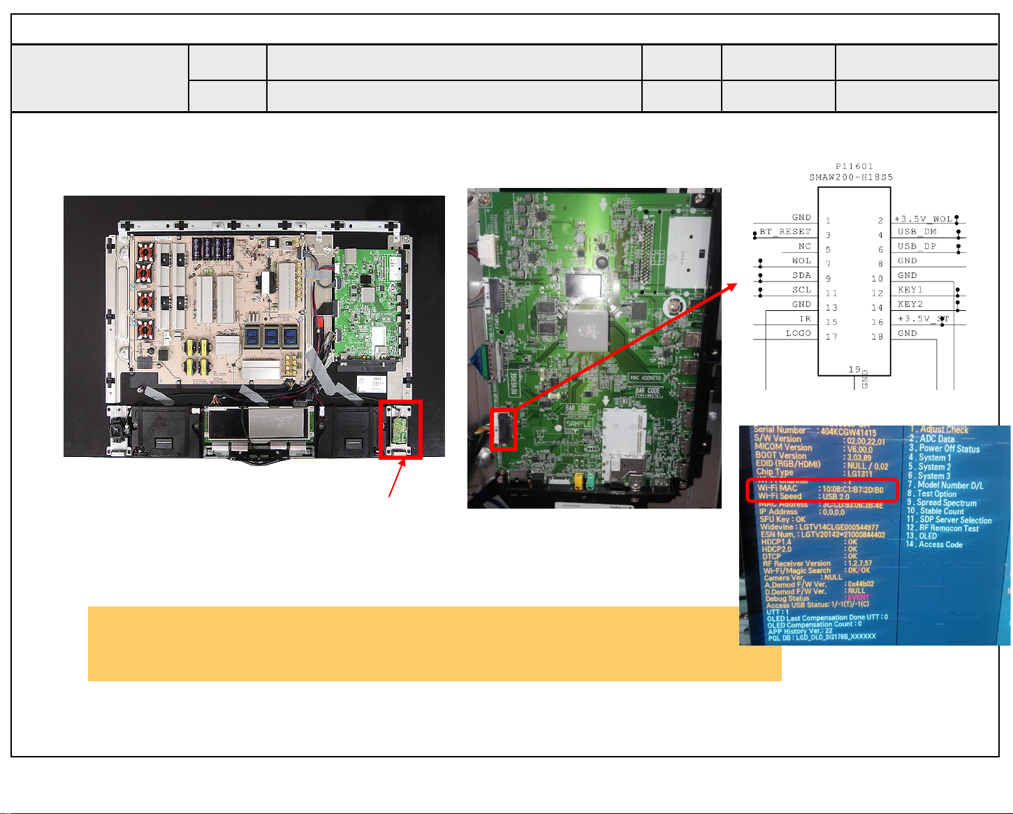
Standard Repair Process Detail Technical Manual
Copyright ⓒ 2015 LG Electronics. Inc. All right reserved.
Only for training and service purposes
LGE Internal Use Only
Error
symptom
Content
Wifi operation checking method
D. Function error
Established
date
Revised
date
A24
Checking order
1, 2 Check the 3.5V_WOL on the terminal 2.
3. Check the WIFI Channel , WIFI SPEED -> MAC , USB2.0(PASS) (USB1.0 ->FAIL)
②
①
Wifi + BT Combo
③
A24
Page 100
Standard Repair Process Detail Technical Manual
Copyright ⓒ 2015 LG Electronics. Inc. All right reserved.
Only for training and service purposes
LGE Internal Use Only
Error
symptom
Content
Camera operation checking method
D. Function error
NO Camera
Established
date
Revised
date
A25
A25
 Loading...