

LG 52LG7000, 32LG7000, 42LG7000, 37LG7000, 47LG7000 Owner's Manual
OWNER’S MANUAL
LCD TV MODELS
3322LLGG7700
****
3377LLGG7700
****
4422LLGG7700
****
4477LLGG7700
****
5522LLGG7700
****
PLASMA TV MODELS
5500 PPGG 7700
****
6600 PPGG 7700** **
LCD TV
PLASMA TV
Please read this manual carefully before operating
your TV.
Retain it for future reference.
Record model number and serial number of the TV.
Refer to the label on the back cover and quote this
information.
To your dealer when requiring service.
ENGLISH
Trade Mark of the DVB Digital Video
Broadcasting Project (1991 to 1996)
IIDD NNuummbbeerr((ss ))::
5512: 32LG7000
5511: 37LG7000
5510: 42LG7000
5530: 47LG7000
5509: 52LG7000
5245: 50PG7000
5244: 60PG7000
This product qualifies for ENERGY STAR in
the “factory default (Home mode)” setting
and this is the setting in which power savings
will be achieved.(Plasma TV only)
0678

1
ACCESSORIES
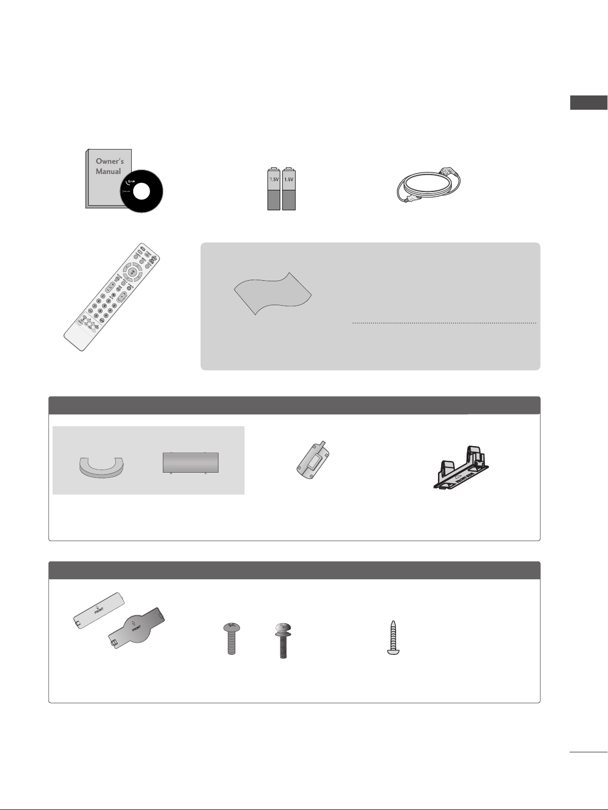
ACCESSORIES
Ensure that the following accessories are included with your TV. If an accessory is missing, please contact the
dealer where you purchased the TV.
■
Image shown may differ from your TV
Owner’s Manual Batteries
Remote Control
Power Cord
Polishing Cloth
Polishing cloth for use on
the screen.
This feature is not available for all models.
* Lightly wipe any stains or fingerprints on
the surface of the TV with the polishing
cloth.
Do not use excessive force. This may cause
scratching or discolouration.
LLCCDD TTVV mmooddeellss
Cable management clip
Protection cover
(Refer to p.13)
Ferrite core
(Refer to p.10)
PPLLAASSMMAA TTVV mmooddeellss
Protection Cover
(Refer to
p
. 13 )
or
Bolts for stand assembly
(Refer to p.8)
x 4
x 4
(32/37/42LG70**only)
1-screw for stand fixing
(Refer to p.12)
(32LG70**only)

CONTENTS
2
CONTENTS
ACCESSORIES
. . . . . . . . . . . . . . . . . . . . . . . . . . . . . . . . . . . . . . . . . . . .
1
PREPARATION
Front Panel Controls..................................................... 4
Back Panel Information ................................................ 6
Stand Installation........................................................... 8
Swivel Stand ................................................................... 8
Please set it up carefully so the product doesn’t fall
over..................................................................................... 9
Back Cover for Wire Arrangement.......................... 10
Desktop Pedestal Installation................................... 12
Attaching the TV to a desk.........................................12
Wall Mount: Horizontal Installation........................ 13
Not Using the desk-type stand.................................13
Antenna Connection................................................... 14
EXTERNAL EQUIPMENT SETUP
HD Receiver Setup...................................................... 15
DVD Setup..................................................................... 17
VCR Setup..................................................................... 20
Insertion of CI Module .............................................. 22
Digital Audio Out Setup............................................ 23
Other A/V Source Setup........................................... 24
Usb in Setup................................................................. 25
PC Setup........................................................................ 26
- Screen Setup for PC Mode .............................. 29
WATCHING TV / PROGRAMME CONTROL
Remote Control Key Functions ............................... 34
Turning on the TV ....................................................... 36
Programme Selection ................................................ 36
Volume Adjustment ................................................... 36
Quick Menu ................................................................. 37
On-Screen Menus Selection and Adjustment..... 38
Auto Programme Tuning ............................................ 39
Manual Programme Tuning (In Digital Mode) ..... 40
Manual Programme Tuning (In Analogue Mode) ... 41
Programme Edit ........................................................... 43
Booster........................................................................... 46
Software Update.......................................................... 47
Diagnostics ................................................................... 48
CI Information.............................................................. 49
Selecting the Programme Table ............................... 50
Input List........................................................................ 51
................................................................. 52
Input Label .................................................................... 54
AV Mode........................................................................ 54
Simple manual .............................................................. 55
TO USE THE BLUETOOTH
Precautions when using the Bluetooth................. 56
Setting the Bluetooth................................................. 57
Set TV PIN......................................................................58
Bluetooth headset
- Connecting a new Bluetooth headset .............59
- Connecting to Bluetooth headset already regis-
tered............................................................................ 59
-
Disconnecting the Bluetooth headset during use
...60
- When requesting to connect to TV from the
Bluetooth headset....................................................60
Managing Registered Bluetooth device................. 61
My Bluetooth Information. ........................................62
Receiving photos through external Bluetooth device...
63
TO USE THE USB DEVICE
When connecting the USB device.......................... 64
Photo List ...................................................................... 65
Music List........................................................................69
EPG (ELECTRONIC PROGRAMME
GUIDE) (IN DIGITAL MODE)
- Switch on/off EPG ............................................... 72
- Select Programme ................................................ 72
- Button Function in NOW/NEXT Guide Mode 73
- Button Function in 8 Day Guide Mode.......... 73
- Button Function in Date Change Mode ......... 73
-
Button Function in Extended Description Box..
74
-
Button Function in Record/Remind Setting Mode
.74
- Button Function in Schedule List Mode......... 74

CONTENTS
3
PICTURE CONTROL
Picture Size (Aspect Ratio) Control....................... 75
Preset Picture Settings
- Picture Mode-Preset............................................ 77
- Auto Colour Tone Control
(Warm/Medium/Cool)..........................................78
Manual Picture Adjustment
- Picture Mode-User option................................. 79
-Picture Mode-Expert Control ............................ 80
Picture Improvement Technology ........................... 81
Advanced - Film Mode/ Real Cinema .................... 82
Advanced - Black(Darkness) Level ......................... 83
Advanced - Trumotion ................................................84
TruMotion Demo ..........................................................85
Eye Care..........................................................................86
Picture Reset................................................................. 87
Power Indicator .............................................................88
Image Sticking Minimization (ISM) Method........ 89
Power Saving Picture Mode...................................... 90
SOUND & LANGUAGE CONTROL
Auto Volume Leveler................................................... 91
Preset Sound Settings - Sound Mode................... 92
Sound Setting Adjustment -User Mode ............... 93
SRS TruSurround XT .................................................. 93
Clear Voice.................................................................... 94
Balance........................................................................... 95
TV Speakers On/ Off Setup .................................... 96
Selecting Digital Audio Out ..................................... 97
Audio Reset....................................................................98
I/II
- Stereo/Dual Reception (In Analogue Mode
Only)........................................................................... 99
- NICAM Reception (In Analogue Mode Only)... 100
- Speaker Sound Output Selection ................. 100
On-Screen Menu Language/Country Selection .... 101
Language Selection (In Digital Mode only)....... 102
TIME SETTING
Clock Setup ................................................................ 103
Auto On/ Off Timer Setting .................................. 104
Auto Shut-off Setting ............................................... 105
Time Zone Setup ...................................................... 106
Sleep Timer Setting .................................................. 106
PARENTAL CONTROL / RATINGS
Set Password & Lock System................................. 107
Block Programme...................................................... 108
Parental Control ........................................................ 109
Key Lock ....................................................................... 110
TELETEXT
Switch on/off............................................................... 111
SIMPLE Text ................................................................. 111
TOP Text ....................................................................... 111
FASTEXT....................................................................... 112
Special Teletext Functions ....................................... 112
DIGITAL TELETEXT
Teletext within Digital Service................................. 113
Teletext in Digital Service......................................... 113
APPENDIX
Troubleshooting ......................................................... 114
Maintenance ............................................................... 116
Product Specifications.............................................. 117
Programming the Remote Control ........................ 119
IR Codes....................................................................... 121
External Control Device Setup .............................. 123
PREPARATION
4
PREPARATION
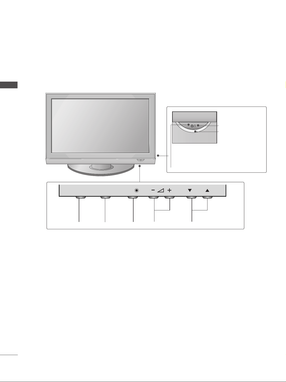
FRONT PANEL CONTROLS
■
Image shown may differ from your TV
■
If your TV has a protection film attached, remove the film and then wipe the product with a polishing cloth.
Plasma TV Models
Remote Control Sensor
POWER
Power/Standby Indicator
• Illuminates red in standby mode.
• Illuminates green when the TV is
switched on.
PROGRAMMEVOLUMEMENU OKINPUT
P
OKOK
MENUMENU
INPUTINPUT
5
PREPARATION
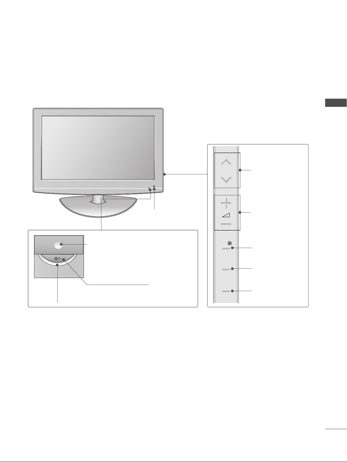
LCD TV Models
POWER
Power/Standby Indicator
• illuminates red in standby mode.
• illuminates blue when the TV is switched on.
Note:
You can adjust
PPoowweerr IInnddiiccaattoorr
in the
Option menu.
PROGRAMME
VOLUME
OK
MENU
INPUT
Intelligent Sensor
Adjusts picture according to the
surrounding conditions.
Remote Control Sensor
P
OK
MENU
INPUT
PREPARATION
6
PREPARATION
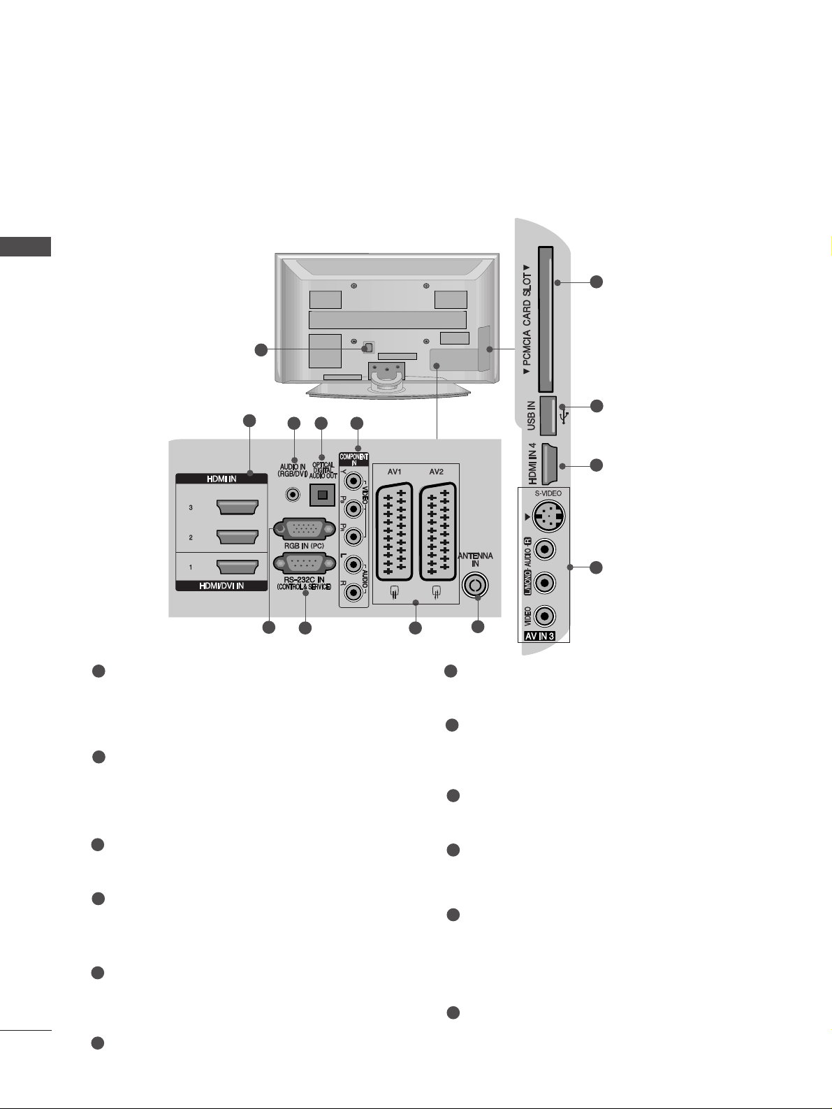
BACK PANEL INFORMATION
A
Image shown may differ from your TV.
Power Cord Socket
This TV operates on an AC power. The voltage is
indicated on the Specifications page. Never
attempt to operate the TV on DC power.
HDMI Input
Connect a HDMI signal to HDMI IN.
Or DVI(VIDEO)signal to HDMI/DVI port with DVI
to HDMI cable.
RGB/DVI Audio Input
Connect the audio from a PC or DTV.
OPTICAL DIGITAL AUDIO OUT
Connect digital audio from various types of equipment.
Note: In standby mode, these ports do not work.
Component Input
Connect a component video/audio device to
these jacks.
RGB Input
Connect the output from a PC.
RS-232C IN (CONTROL & SERVICE) PORT
Connect to the RS-232C port on a PC.
Euro Scart Socket (AV1/AV2)
Connect scart socket input or output from an
external device to these jacks.
Antenna Input
Connect RF antenna to this jack.
PCMCIA (Personal Computer Memory Card
International Association) Card Slot
(This feature is not available in all countries.)
S-Video Input
Connect S-Video out from an S-VIDEO device.
Audio/Video Input
Connect audio/video output from an external
device to these jacks.
USB Input
1
2
3
4
7
8
9
10
11
12
1
5
6
2
3 4 5
6
7 8
9
Plasma TV Models
10
12
2
11
7
PREPARATION
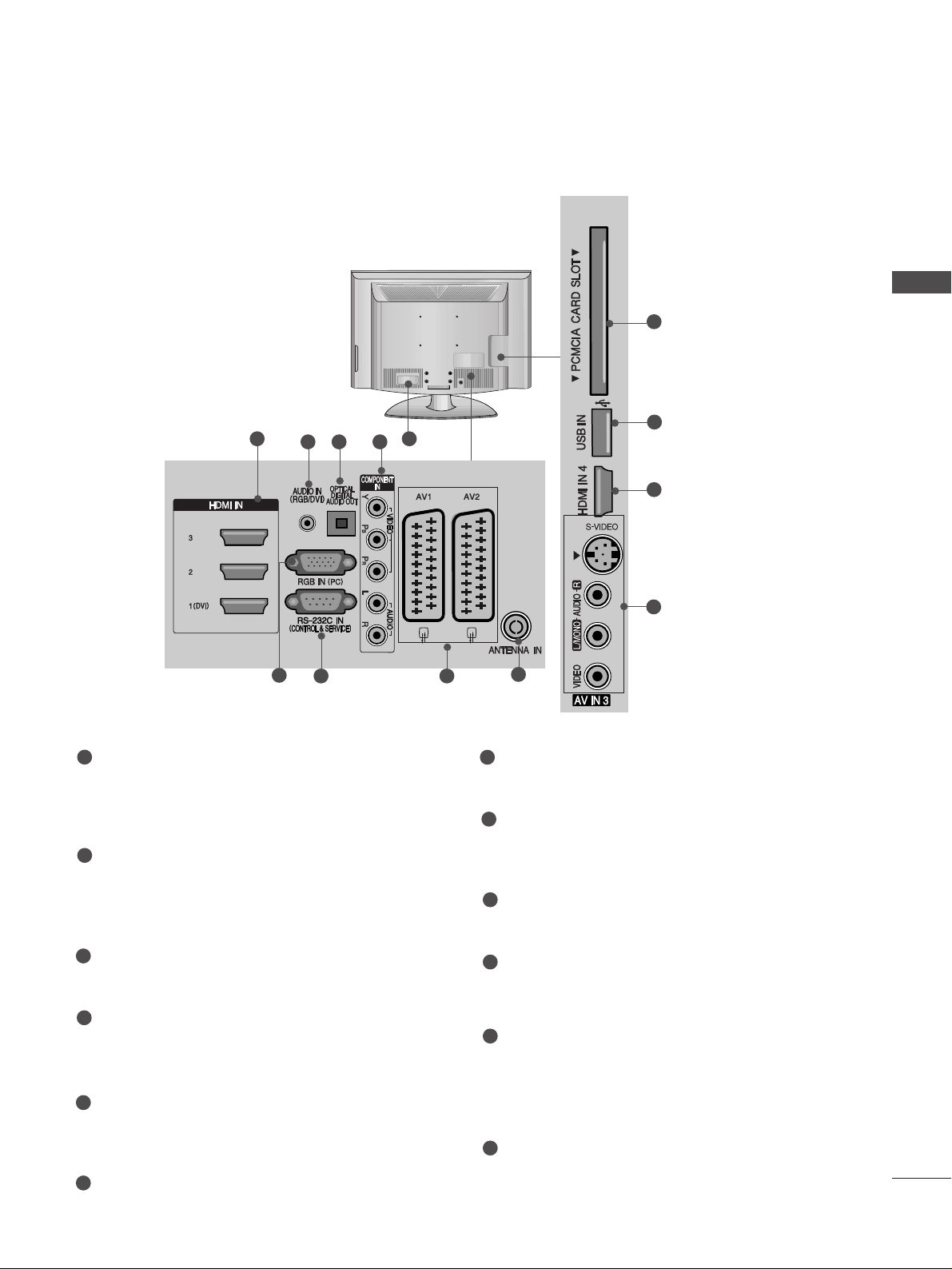
LCD TV Models
1
Power Cord Socket
This TV operates on an AC power. The voltage is
indicated on the Specifications page. Never
attempt to operate the TV on DC power.
HDMI Input
Connect a HDMI signal to HDMI IN.
Or DVI(VIDEO)signal to HDMI/DVI port with DVI
to HDMI cable.
RGB/DVI Audio Input
Connect the audio from a PC or DTV.
OPTICAL DIGITAL AUDIO OUT
Connect digital audio from various types of equipment.
Note: In standby mode, these ports do not work.
Component Input
Connect a component video/audio device to
these jacks.
RGB Input
Connect the output from a PC.
RS-232C IN (CONTROL & SERVICE) PORT
Connect to the RS-232C port on a PC.
Euro Scart Socket (AV1/AV2)
Connect scart socket input or output from an
external device to these jacks.
Antenna Input
Connect RF antenna to this jack.
PCMCIA (Personal Computer Memory Card
International Association) Card Slot
(This feature is not available in all countries.)
S-Video Input
Connect S-Video out from an S-VIDEO device.
Audio/Video Input
Connect audio/video output from an external
device to these jacks.
USB Input
1
2
3
4
7
8
9
10
11
12
5
6
2
3 4 5
6
7 8
9
10
12
2
11
PREPARATION
8
PREPARATION
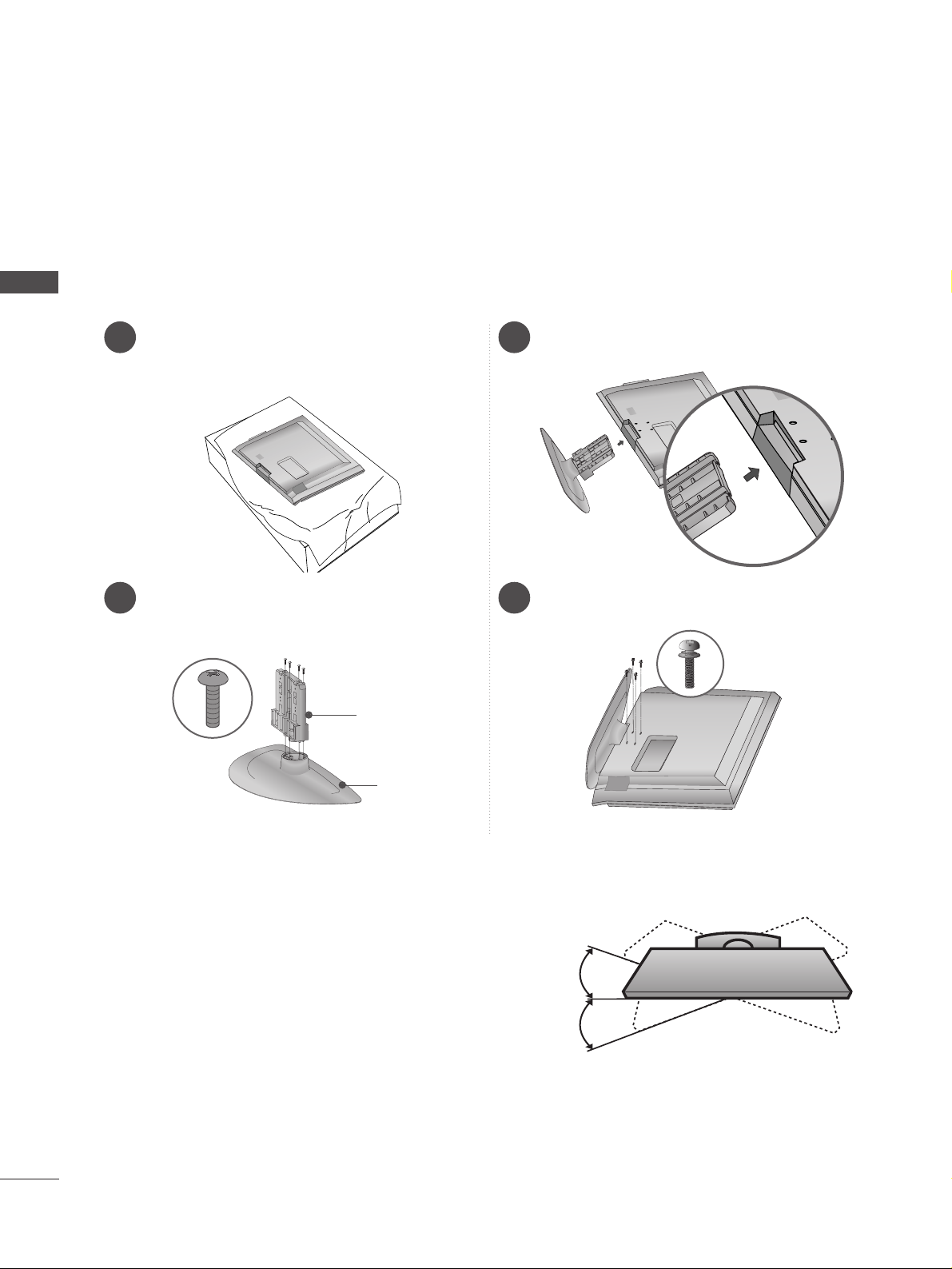
STAND INSTALLATION
■
Image shown may differ from your TV
When assembling the desk type stand, check whether the bolt is fully tightened. (If not tightened fully, the product can
tilt forward after the product installation.) If you tighten the bolt with excessive force, the bolt can deviate from abrasion
of the tightening part of the bolt.
1 3
4
Carefully place the TV screen side down on a
cushioned surface to protect the screen from
damage.
2
Assemble the parts of the
SS tt aa nndd BB ooddyy
with
the
CC oo vveerr BB aa ssee
of the TV.
Assemble the TV as shown.
Fix the 4 bolts securely using the holes in the
back of the TV.
Stand Body
Cover Base
32/37/42LG70
**
only
SWIVEL STAND
After installing the TV, you can adjust the TV set manually to the left or right direction by 20 degrees to
suit your viewing position.
PREPARATION
9
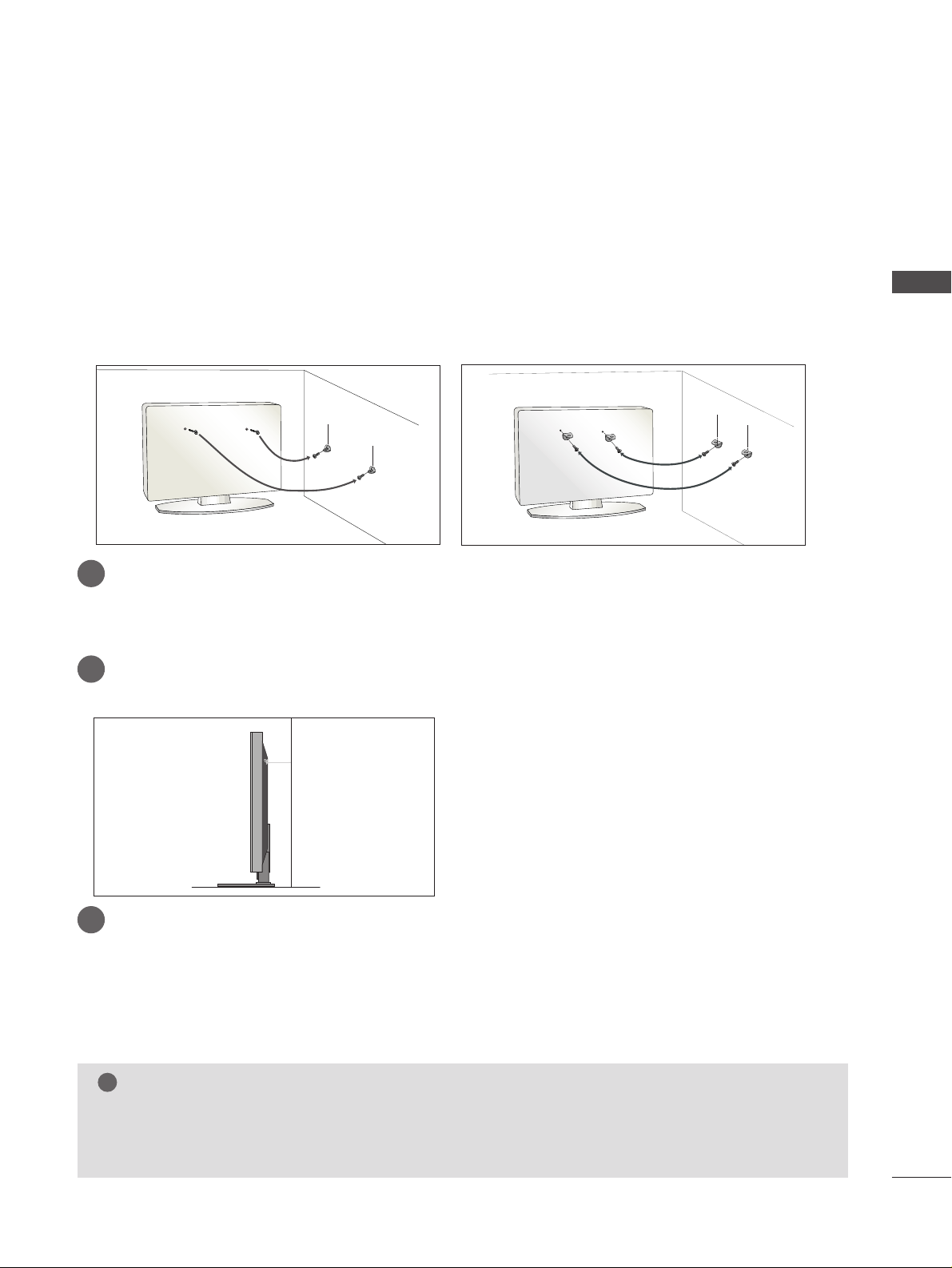
PLEASE SET IT UP CAREFULLY SO THE PRODUCT DOESN’T FALL OVER.
2
1
A
You should purchase necessary components to fix the TV to the wall on the market.
A
Position the TV close to the wall to avoid the possibility of it falling when pushed.
A
The instructions shown below are a safer way to set up the TV, which is to fix it to the wall, avoiding the
possibility of it falling forwards if pulled. This will prevent the TV from falling forward and causing injury.
This will also prevent the TV from damage. Ensure that children do not climb or hang from the TV.
NOTE
!
G
When moving the TV undo the cords first.
G
Use a platform or cabinet strong and large enough to support the size and weight of the TV.
G
To use the TV safely make sure that the height of the bracket on the wall and on the TV is the same.
2
3
1
1
2
Use the eye-bolts or TV brackets/bolts to fix the product to the wall as shown in the picture.
(If your TV has bolts in the eyebolts, loosen then bolts.)
* Insert the eye-bolts or TV brackets/bolts and tighten them securely in the upper holes.
Secure the wall brackets with the bolts on the wall. Match the height of the bracket that is mounted on the
wall.
3
Use a sturdy rope to tie the product. It is safer to tie the rope so it becomes horizontal between
the wall and the product.
PREPARATION
10
PREPARATION
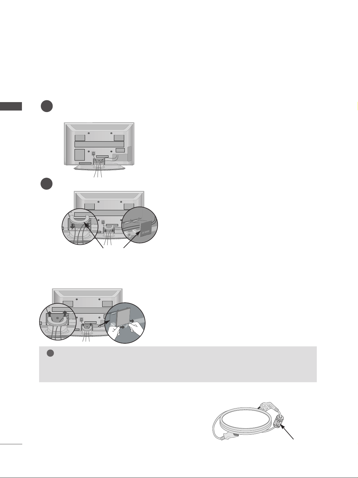
BACK COVER FOR WIRE ARRANGEMENT
Connect the cables as necessary.
To connect additional equipment, see the
EExxtteerrnnaall eeqq uuiippmmeenntt SSeettuupp
section.
1
Install the
CCAABBLLEE MMAANNAAGGEEMMEENNTT CCLLIIPP
as shown.
2
NOTE
!
GG
Do not use the CABLE MANAGEMENT CLIP to lift the TV.
- If the TV is dropped, you may be injured or the TV may be damaged.
■
Image shown may differ from your TV.
Install the power plug closely.
Use of ferrite core
(50/60PG70** Only)
Ferrite core can be used to reduce the electromagnetic
wave when connecting the power cord.
The closer the location of the ferrite core to the power
plug, the better it is.
Plasma TV models
Hold the
CC AABBLLEE MMAANN AAGGEE MMEE NNTT CCLLIIPP
with both hands and pull it upward.
How to remove the cable management clip
Separate CABLE MANAGEMENT
from TV by pressing two latches.
CABLE MANAGEMENT CLIP
11
PREPARATION
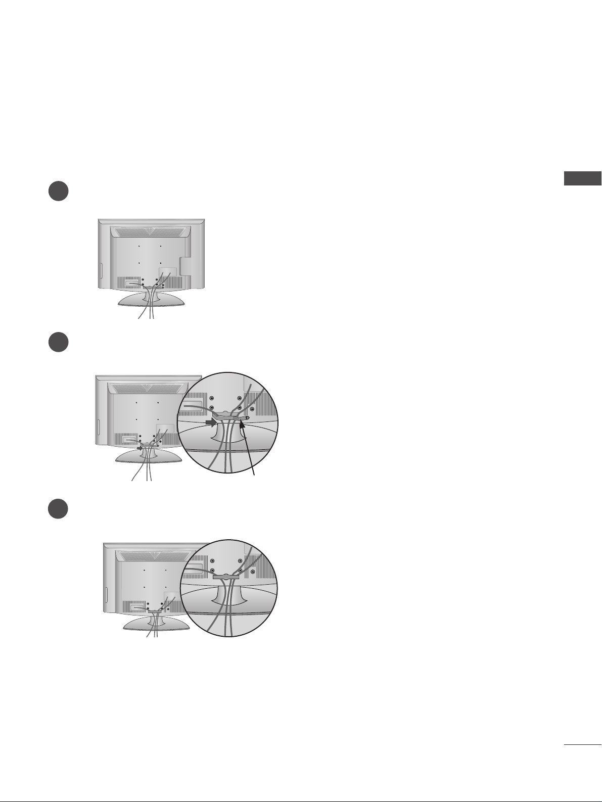
LCD TV models
Connect the cables as necessary.
To connect additional equipment, see the External Equipment Setup section of the manual.
1
Open the
CC AABBLLEE MMAANN AAGGEE MMEE NNTT CCLLIIPP
as shown and manage the cables.
2
CABLE MANAGEMENT CLIP
Fit the
CC AABBLLEE MMAANN AAGGEE MMEE NNTT CCLLIIPP
as shown.
3
4 inches
4 inches 4 inches
4 inches
12
PREPARATION
PREPARATION
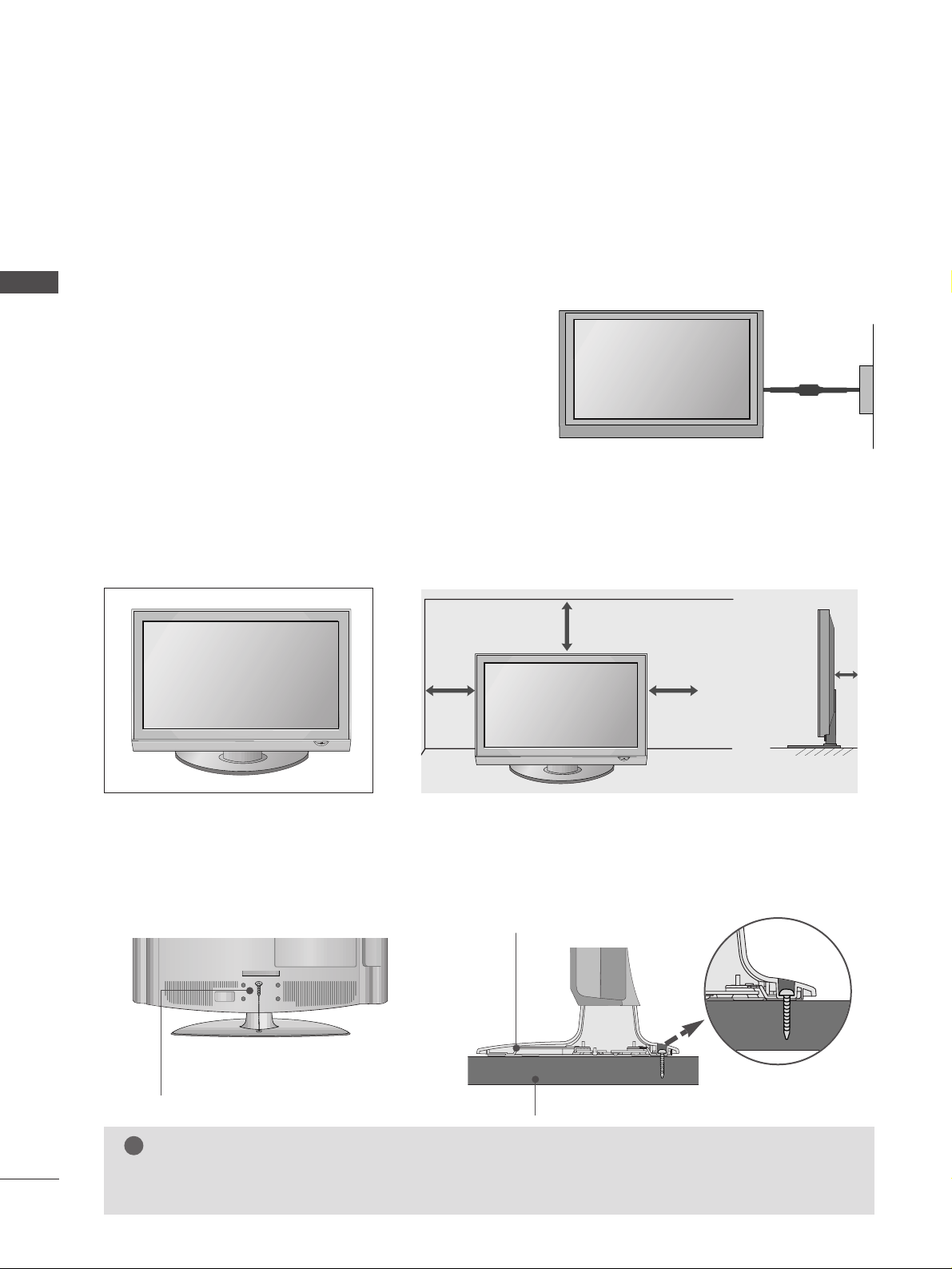
DESKTOP PEDESTAL INSTALLATION
A
The TV can be installed in various ways such as on a wall, or on a desktop etc.
A
The TV is designed to be mounted horizontally.
Power Supply
Circuit breaker
EARTHING
Ensure that you connect the earth wire to prevent possible
electric shock. If grounding methods are not possible, have a
qualified electrician install a separate circuit breaker.
Do not try to earth the TV by connecting it to telephone
wires, lightening rods or gas pipes.
For adequate ventilation allow a clearance of 4” (10cm) all around the TV.
ATTACHING THE TV TO A DESK (32LG70
**
only )
The TV must be attached to desk so it cannot be pulled in a forward/backward direction, potentially causing
injury or damaging the product. Use only an attached screw.
1-Screw
(provided as parts of the product)
Desk
Stand
WARNING
!
G
To prevent TV from falling over, the TV should be securely attached to the floor/wall per installation
instructions. Tipping, shaking, or rocking the machine may cause injury.
13
PREPARATION
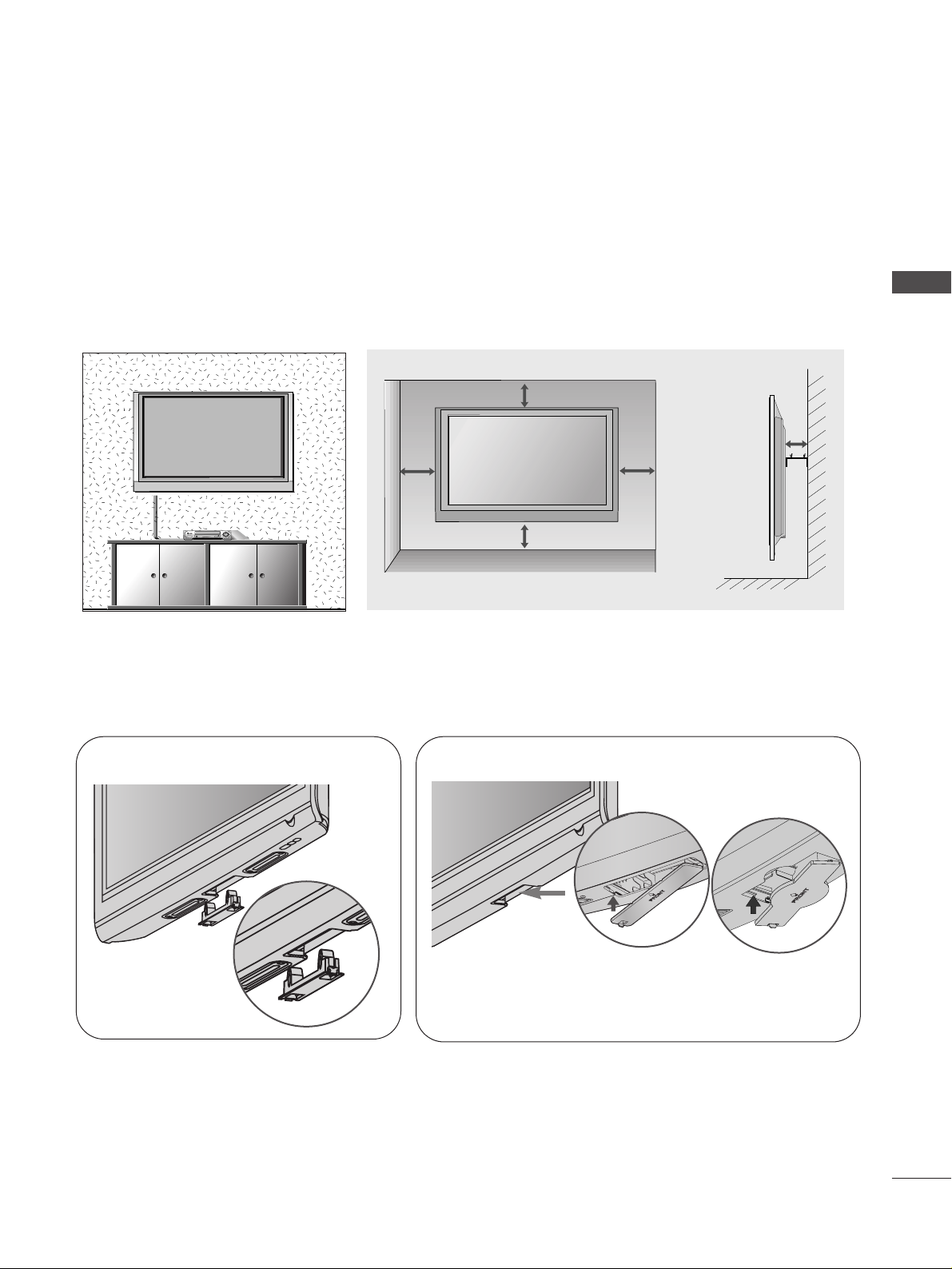
WALL MOUNT: HORIZONTAL INSTALLATION
For adequate ventilation allow a clearance of 4” (10cm) all around the TV. We recommend that you
use a wall mount-ing bracket of LG brand when mounting the TV to a wall.
4 inches
4 inches
4 inches
4 inches
4 inches
■
Image shown may differ from your TV.
When installing the wall-mounted unit, use the protection cover for desk-type stand installation.
NOT USING THE DESK-TYPE STAND
Plasma TV models
LCD TV models
Insert the
PP RROOTTEE CCTTIIOONN CCOO VVEE RR
into the TV until
clicking sound.
PREPARATION
14
PREPARATION
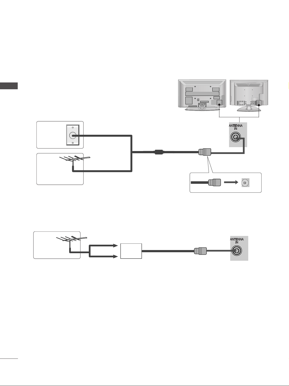
ANTENNA CONNECTION
■
For optimum picture quality, adjust antenna direction.
■
An antenna cable and converter are not supplied.
■
To prevent damage do not connect to the mains outlet until all connections are made between the devices.
Multi-family Dwellings/Apartments
(Connect to wall antenna socket)
Single-family Dwellings /Houses
(Connect to wall jack for outdoor antenna)
Outdoor
Antenna
(VHF, UHF)
Wall
Antenna
Socket
RF Coaxial Wire (75 ohm)
Antenna
UHF
Signal
Amplifier
VHF
■
In poor signal areas, to achieve better picture quality it may be necessary to install a signal amplifier to the
antenna as shown above.
■
If signal needs to be split for two TVs,use an antenna signal splitter for connection.
15
EXTERNAL EQUIPMENT SETUP
EXTERNAL EQUIPMENT SETUP
HD RECEIVER SETUP
■
To avoid damaging any equipment, never plug in any power cords until you have finished connecting all equipment.
■
This section on EXTERNAL EQUIPMENT SETUP mainly uses diagrams for the 50PG70**models.
■
Image shown may differ from your TV.
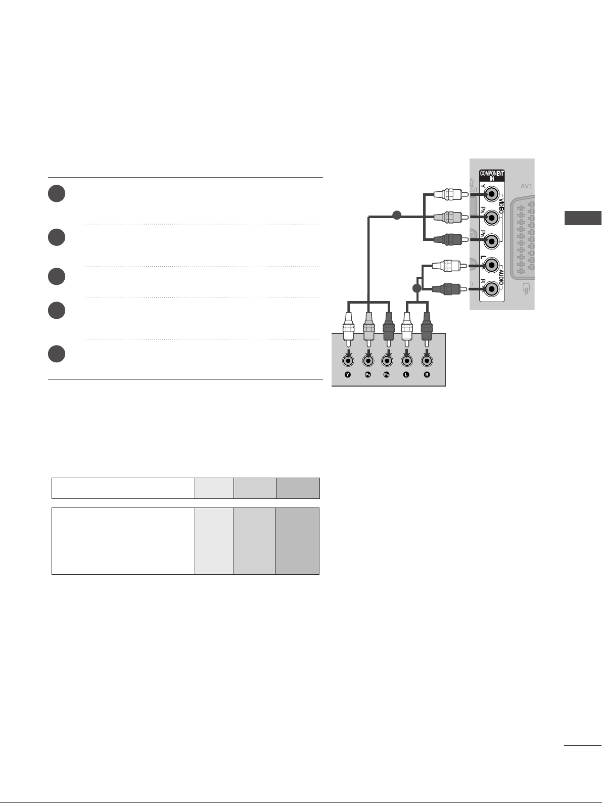
Connecting with a component cable
1
2
Signal
480i/576i
480p/576p
720p/1080i
10 8 0 p
Component
Yes
Yes
Yes
Yes
(50/60Hz only)
HDMI
No
Yes
Yes
Yes
(24Hz/30Hz/50Hz/60Hz)
■
This TV can receive Digital RF/Cable signals without an external digital set-top box. However, if you do receive
Digital signals from a digital set-top box or other digital external device, refer to the diagram as shown below.
Connect the video outputs (Y, P
B, PR
)
of the digital set
top box to the
CC OOMMPPOO NNEENNTT II NN VV IIDDEEOO
jacks on the
TV.
Connect the audio output of the digital set-top box to
the
CC OOMMPPOO NNEENNTT II NN AAUUDD II OO
jacks on the TV.
Turn on the digital set-top box.
(
Refer to the owner’s manual for the digital set-top box.
)
Select
CC oo mm ppoonneenn tt
input source using the
II NNPPUUTT
button on the remote control.
2
3
4
1
16
EXTERNAL EQUIPMENT SETUP
EXTERNAL EQUIPMENT SETUP
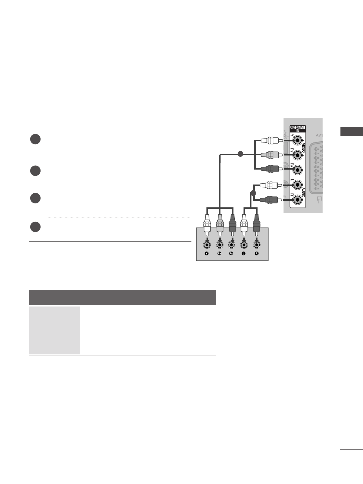
Connecting a set-top box with an HDMI cable
1
Connecting with an HDMI to DVI cable
1
2
Connect the digital set-top box to
HHDD MMII //DD VVII II NN 11
,
HHDDMMII II NN 22,HHDDMMII II NN 33
or
HHDDMMII II NN 44
jack on the
TV.
Turn on the digital set-top box.
(
Refer to the owner’s manual for the digital set-top box.
)
Select
HH DD MMII11, HH DD MMII22, HH DD MMII33
or
HH DD MMII44
input
source using the
II NNPPUUTT
button on the remote control.
2
3
1
Connect the digital set-top box to
HHDD MMII //DD VVII IINN 11
jack on the TV.
Connect the audio output of the digital set-top box to
the
AAUUDDIIOO IINN (( RRGG BB// DDVV II))
jack on the TV.
Turn on the digital set-top box. (Refer to the owner’s
manual for the digital set-top box.
)
Select
HH DD MMII11
input source using the
II NNPPUU TT
button
on the remote control.
2
3
4
1
17
EXTERNAL EQUIPMENT SETUP
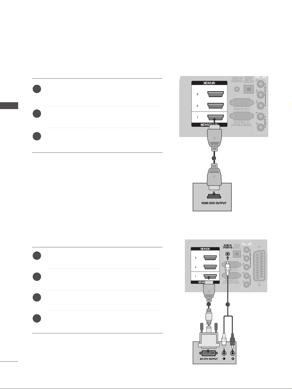
DVD SETUP
Connecting with a component cable
Component Input ports
To achieve better picture quality, connect a DVD player to the component input ports as shown below.
Component ports on the TV
YPBP
R
Video output ports
on DVD player
Y
Y
Y
Y
PB
B-Y
Cb
Pb
P
R
R-Y
Cr
Pr
1
2
Connect the video outputs (Y, PB, P
R
)
of the DVD to the
CC OOMMPPOO NNEENNTT II NN VV IIDD EEOO
jacks on the TV.
Connect the audio outputs of the DVD to the
CC OOMMPPOO NNEENNTT II NN AAUUDD II OO
jacks on the TV.
Turn on the DVD player, insert a DVD.
Select
CC oo mm ppoonneenntt
input source using the
II NNPPUU TT
button on the remote control.
Refer to the DVD player's manual for operating instruc-
tions.
2
3
4
5
1
18
EXTERNAL EQUIPMENT SETUP
EXTERNAL EQUIPMENT SETUP
1
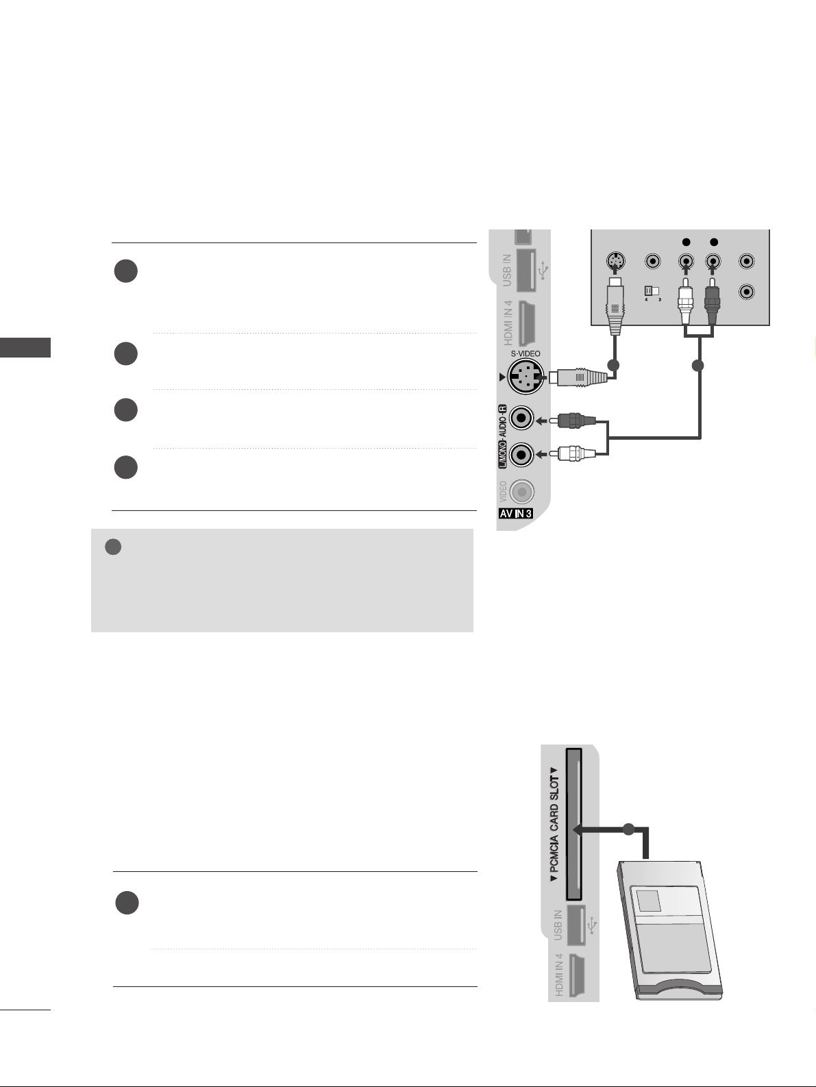
Connecting with a S-Video cable
L R
S-VIDEOVIDEO
OUTPUT
SWITCH
ANT IN
ANT OUT
Connect the S-VIDEO output of the DVD to the
SS --
VVIIDD EEOO
input on the TV.
Connect the audio outputs of the DVD to the
AAUU DDIIOO
input jacks on the TV.
Turn on the DVD player, insert a DVD.
Select
AA VV33
input source using the
II NNPPUU TT
button on
the remote control.
Refer to the DVD player's manual for operating instructions.
2
3
4
5
1
2
3
4
1
1
2
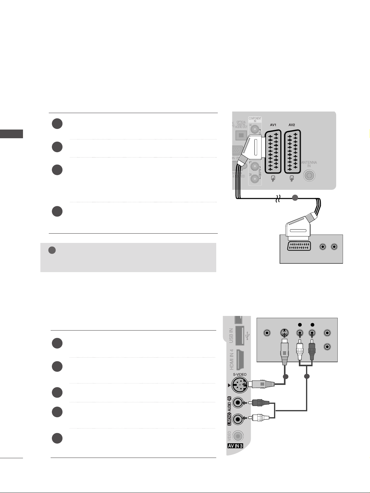
Connecting with a Euro Scart cable
Connect the Euro scart socket of the DVD to the
AAVV 11
Euro scart socket on the TV.
Turn on the DVD player, insert a DVD.
Select
AA VV11
input source using the
II NNPPUU TT
button on
the remote control.
If connected to
AA VV22
Euro scart socket, select
AA VV22
input source.
Refer to the DVD player's manual for operating
instructions.
NOTE
!
GG
Any Euro scart cable used must be signal shielded.
AUDIO/
VIDEO
(R) AUDIO (L)
19
EXTERNAL EQUIPMENT SETUP
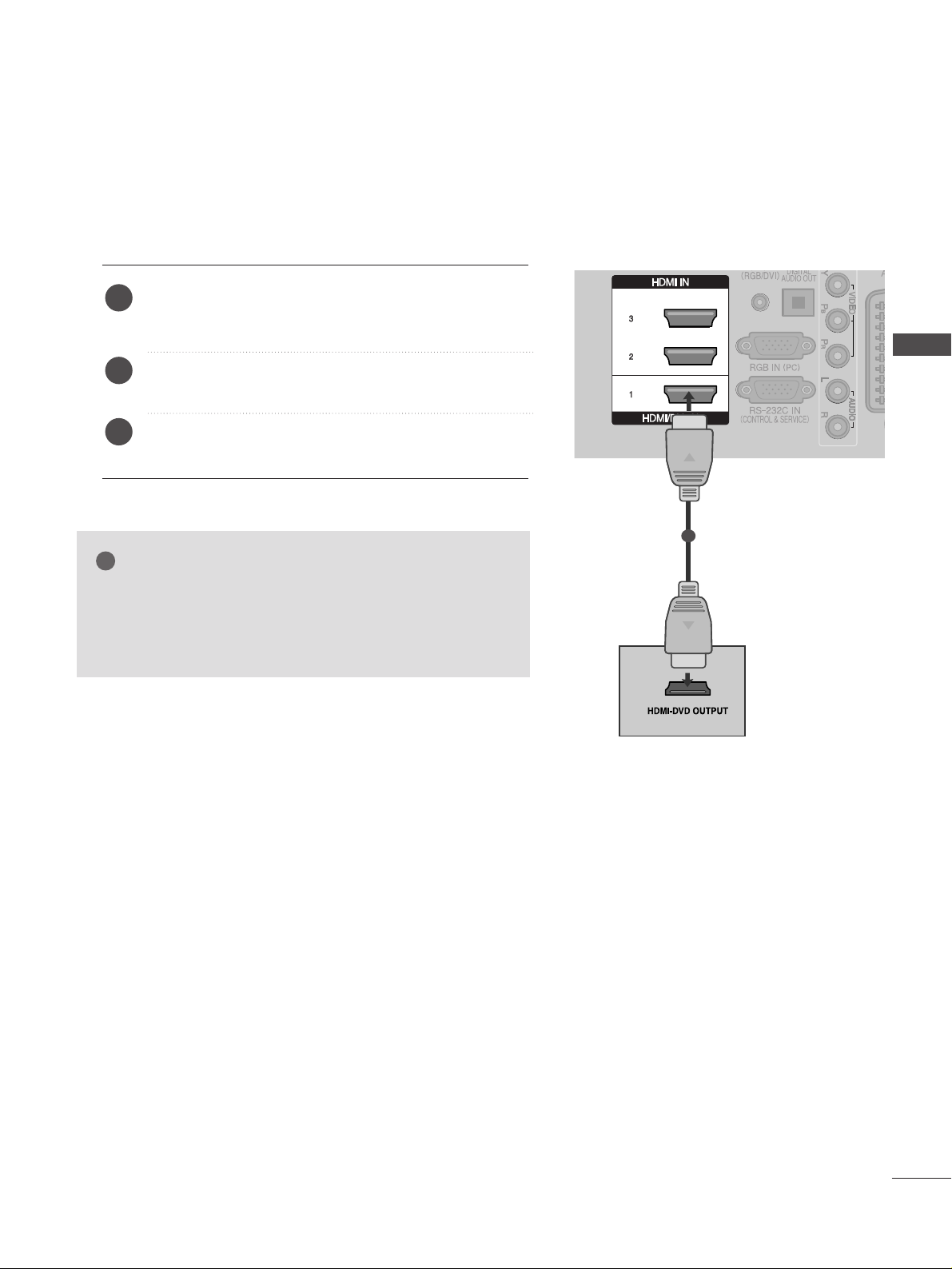
Connecting the HDMI cable
Connect the HDMI output of the DVD to the
HHDD MMII //DD VVII II NN 11,HHDDMMII II NN 22,HHDDMMII II NN 33
or
HHDDMMII
II NN 44
jack on the TV.
Select
HH DD MMII11, HH DD MMII22, HH DD MMII33
or
HH DD MMII44
input
source using the
II NNPPUUTT
button on the remote control.
Refer to the DVD player's manual for operating instructions.
2
3
1
1
GG
The TV can receive video and audio signals simultaneously
when using a HDMI cable.
GG
If the DVD does not support Auto HDMI, you must set the
output resolution appropriately.
NOTE
!
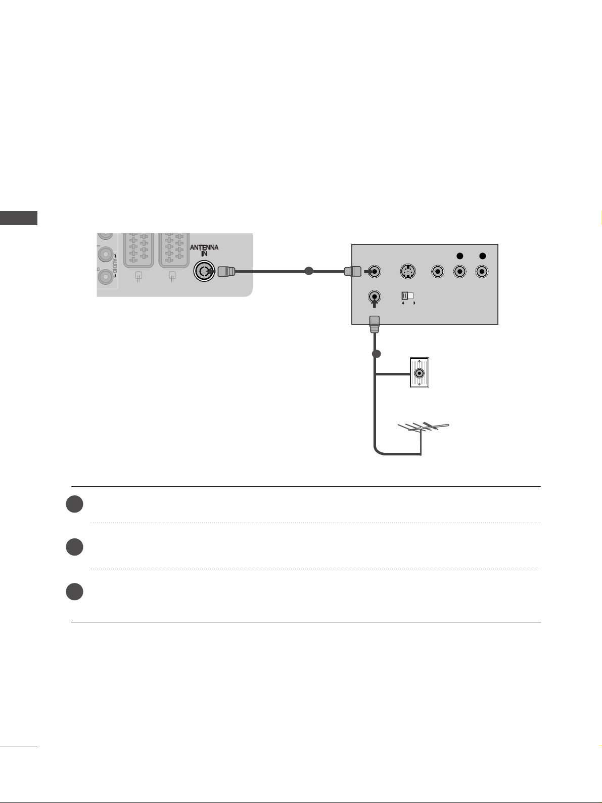
VCR SETUP
■
To avoid picture noise (interference), allow adequate distance between the VCR and TV.
■
Typically a frozen still picture from a VCR. If 4:3 picture format is used for an extended period the fixed
images on the sides of the screen may remain visible.
OUTPUT
SWITCH
ANT IN
R
S-VIDEO VIDEO
ANT OUT
L
Wall Jack
Antenna
1
2
Connecting with a RF Cable
20
EXTERNAL EQUIPMENT SETUP
EXTERNAL EQUIPMENT SETUP
Connect the
AANNTT OO UU TT
socket of the VCR to the
AANNTT EENNNN AA IINN
socket on the TV.
Connect the antenna cable to the
AANNTT IINN
socket of the VCR.
Press the
PP LLAA YY
button on the VCR and match the appropriate channel between the TV and VCR for
viewing.
2
3
1
21
EXTERNAL EQUIPMENT SETUP
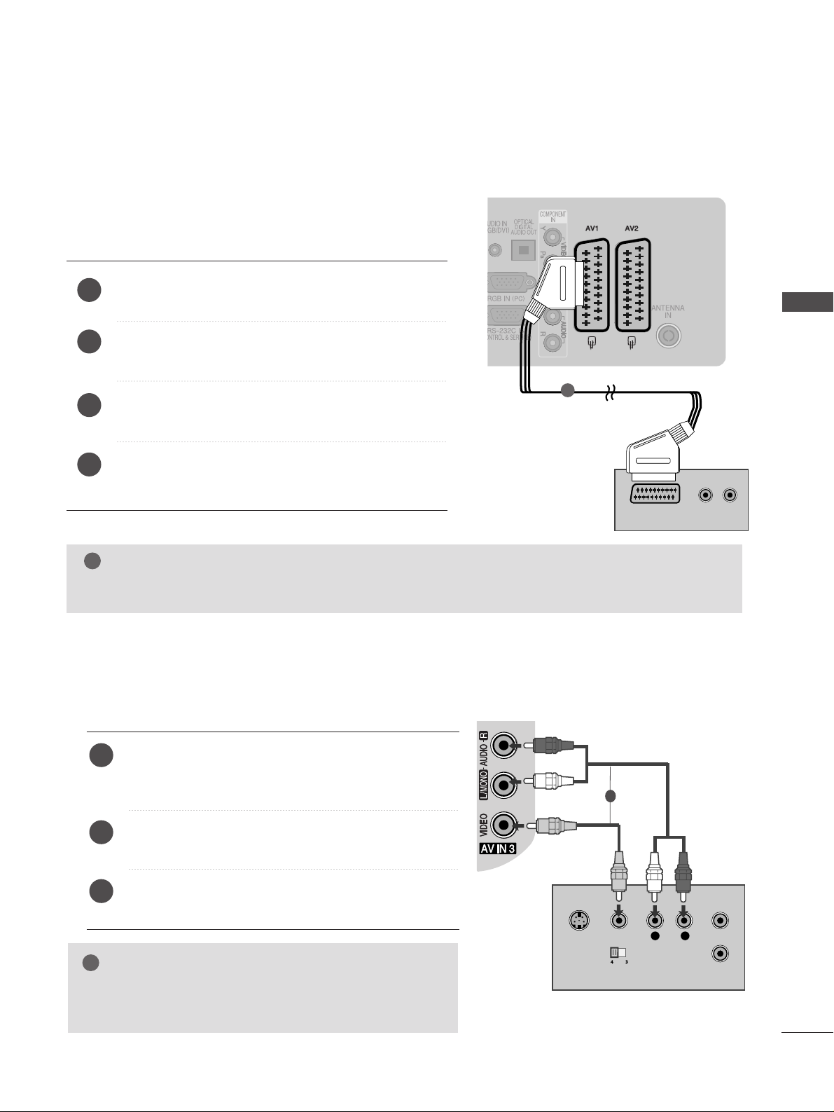
(R) AUDIO (L)
AUDIO/
VIDEO
Connecting with a Euro Scart cable
1
Connect the Euro scart socket of the VCR to the
AAVV 11
Euro scart socket on the TV.
Insert a video tape into the VCR and press PLAY on
the VCR. (Refer to the VCR owner’s manual.)
Select
AA VV11
input source using the
II NNPPUU TT
button on
the remote control.
If connected to
AAVV 22
Euro scart socket, select
AA VV22
input source.
2
3
4
1
Connecting with a RCA cable
L
R
S-VIDEO
VIDEO
OUTPUT
SWITCH
ANT IN
ANT OUT
Connect the
AAUU DD II OO/VVIIDD EEOO
jacks between TV and
VCR. Match the jack colours (Video = yellow, Audio Left
= white, and Audio Right = red)
Insert a video tape into the VCR and press PLAY on
the VCR. (Refer to the VCR owner’s manual.
)
Select
AA VV33
input source using the
II NNPPUUTT
button on
the remote control.
1
2
3
GG
If you have a mono VCR, connect the audio cable from the
VCR to the
AAUU DDIIOO LL//MMOONN OO
jack of the TV.
NOTE
!
1
NOTE
!
GG
Any Euro Scart cable used must be signal shielded.
22
EXTERNAL EQUIPMENT SETUP
EXTERNAL EQUIPMENT SETUP
GG
If both S-VIDEO and VIDEO sockets have been connected to
the S-VHS VCR simultaneously, only the S-VIDEO can be
received.
NOTE
!
L
R
S-VIDEO
VIDEO
OUTPUT
SWITCH
ANT IN
ANT OUT
Connecting with a S-Video cable
Connect the S-VIDEO output of the VCR to the
SS --
VVIIDD EEOO
input on the TV set. The picture quality is
improved; compared to normal composite (RCA cable)
input.
Connect the audio outputs of the VCR to the
AAUU DDIIOO
input jacks on the TV.
Insert a video tape into the VCR and press PLAY on the
VCR. (Refer to the VCR owner’s manual.)
Select
AA VV33
input source with using the
IINNPPUUTT
button on
the remote control.
2
3
4
1
1
2
Insert the CI Module to
PP CC MMCC II AA
(Personal Computer
Memory Card International Association)
CC AARR DD SSLL OOTT
of TV as shown.
For further information, see p.49.
1
INSERTION OF CI MODULE
TVTVTV
-- TToo vvii eeww tthhee eennccrryy pptteedd ((ppaa yy)) ss eerrvviicceess ii nn ddiiggii tt aall TTVV
mm oo dd ee ..
-- TThhii ss ff eeaatt uurree iiss nnoott aa vvaaii llaa bb ll ee ii nn aa llll ccoouunnttrriiee ss..
1
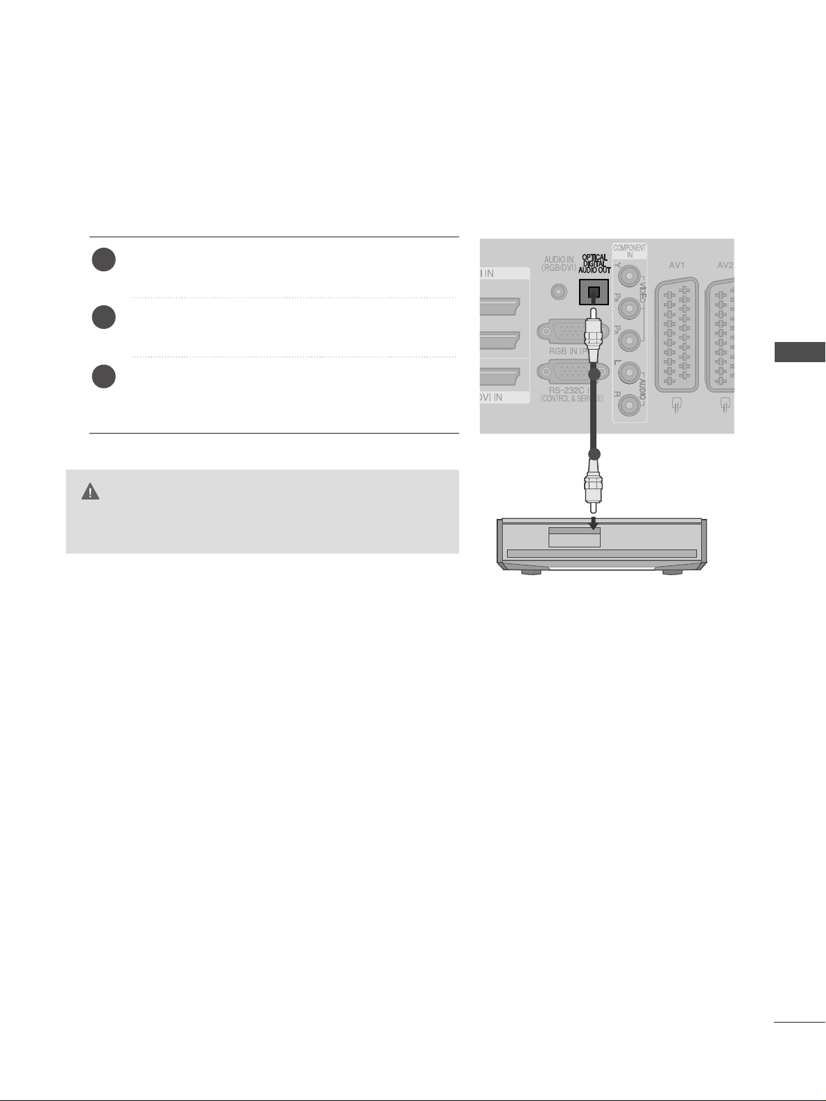
G
Do not look into the optical output port. Looking at the
laser beam may damage your vision.
CAUTION
Connect one end of an optical cable to the TV Digital
Audio (Optical)Output port.
Connect the other end of the optical cable to the digital audio (Optical)input on the audio equipment.
Set the “TV Speaker option - Off ” in the AUDIO
menu.(
G
pp..9966
). Refer to the external audio equipment
instruction manual for operation.
2
3
1
1
2
23
EXTERNAL EQUIPMENT SETUP
DIGITAL AUDIO OUT SETUP
Sending the TV’s audio signal to external audio equipment via the Digital Audio Output (Optical) port.
24
EXTERNAL EQUIPMENT SETUP
EXTERNAL EQUIPMENT SETUP
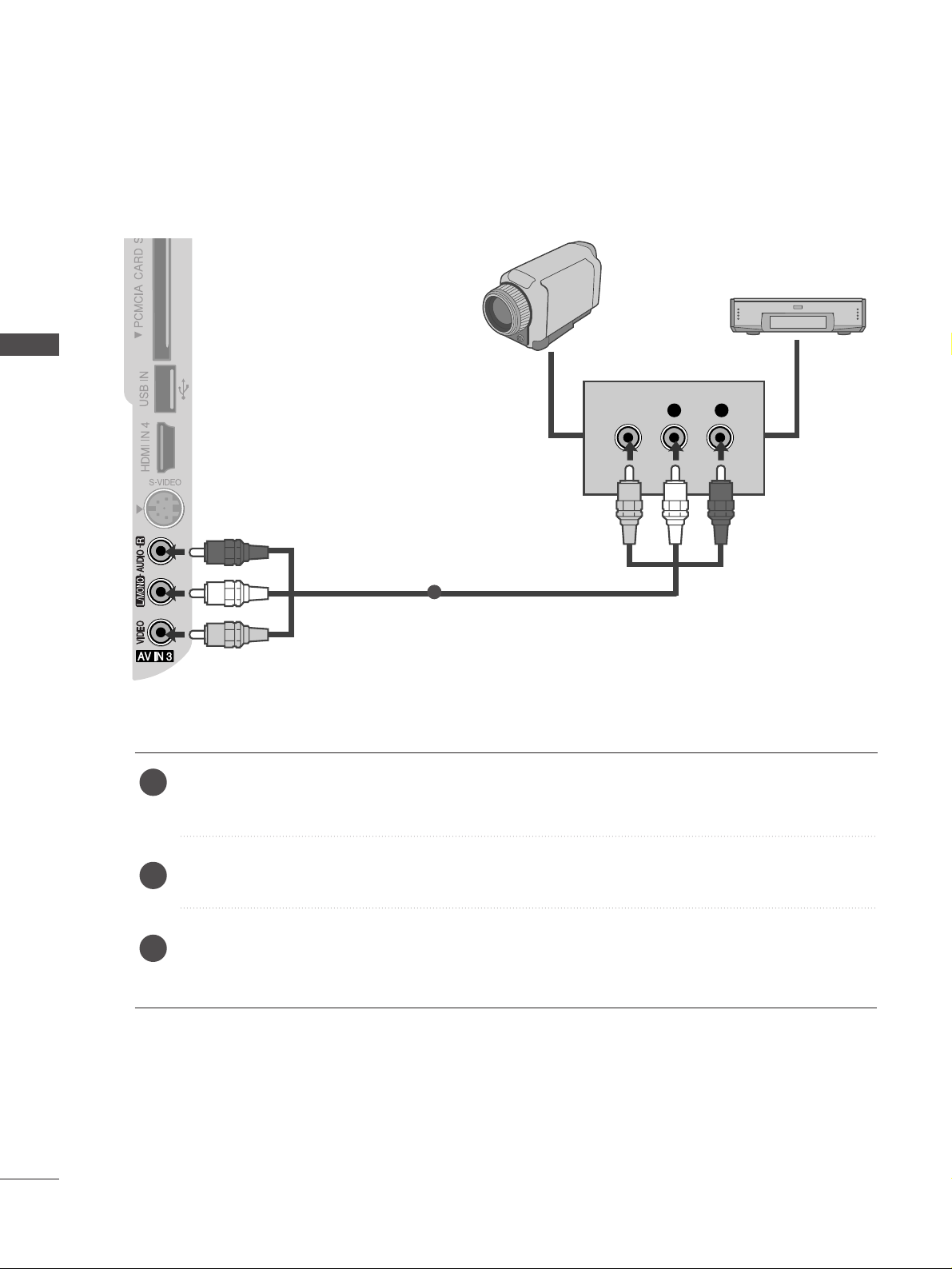
OTHER A/V SOURCE SETUP
Connect the
AAUU DDIIOO/VVIIDD EEOO
jacks between TV and external equipment. Match the jack colours
.
(
Video = yellow, Audio Left = white, and Audio Right = red
)
Select
AA VV33
input source with using the
II NNPPUU TT
button on the remote control.
Operate the corresponding external equipment.
Refer to external equipment operating guide.
L R
VIDEO
Camcorder
Video Game Set
1
1
2
3
25
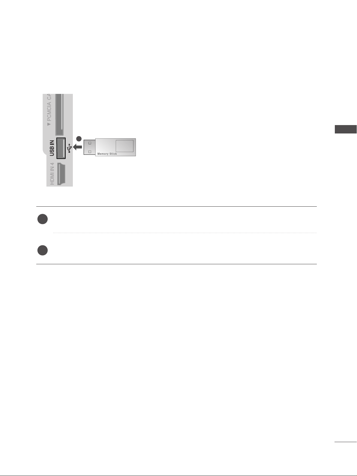
EXTERNAL EQUIPMENT SETUP
USB IN SETUP
Connect the USB device to the
UUSSBB IINN
jacks on the side of TV.
After connecting the
UUSSBB IINN
jacks, you use the
UU SS BB
function. (
GG
pp..6644
)
2
1
1
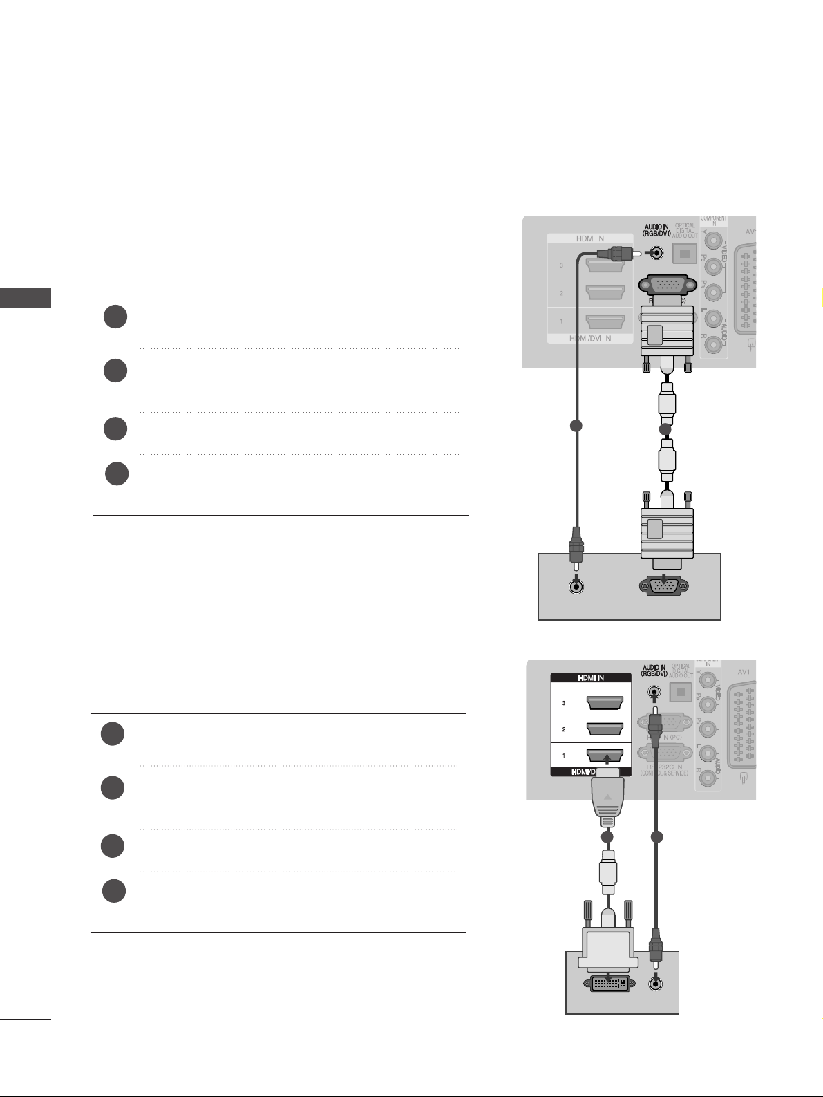
PC SETUP
This TV provides Plug and Play capability, meaning that the PC adjusts automatically to the TV's settings.
Connecting with a D-sub 15 pin cable
AUDIO
RGB OUTPUT
1
2
4
Connect the RGB output of the PC to the
RRGG BB IINN
(( PP CC ))
jack on the TV.
Connect the PC audio output to the
AAUU DDIIOO IINN
((RRGGBB // DDVV II))
jack on the TV.
Turn on the PC and the TV
Select
RRGGBB
input source using the INPUT button on
the remote control.
2
3
1
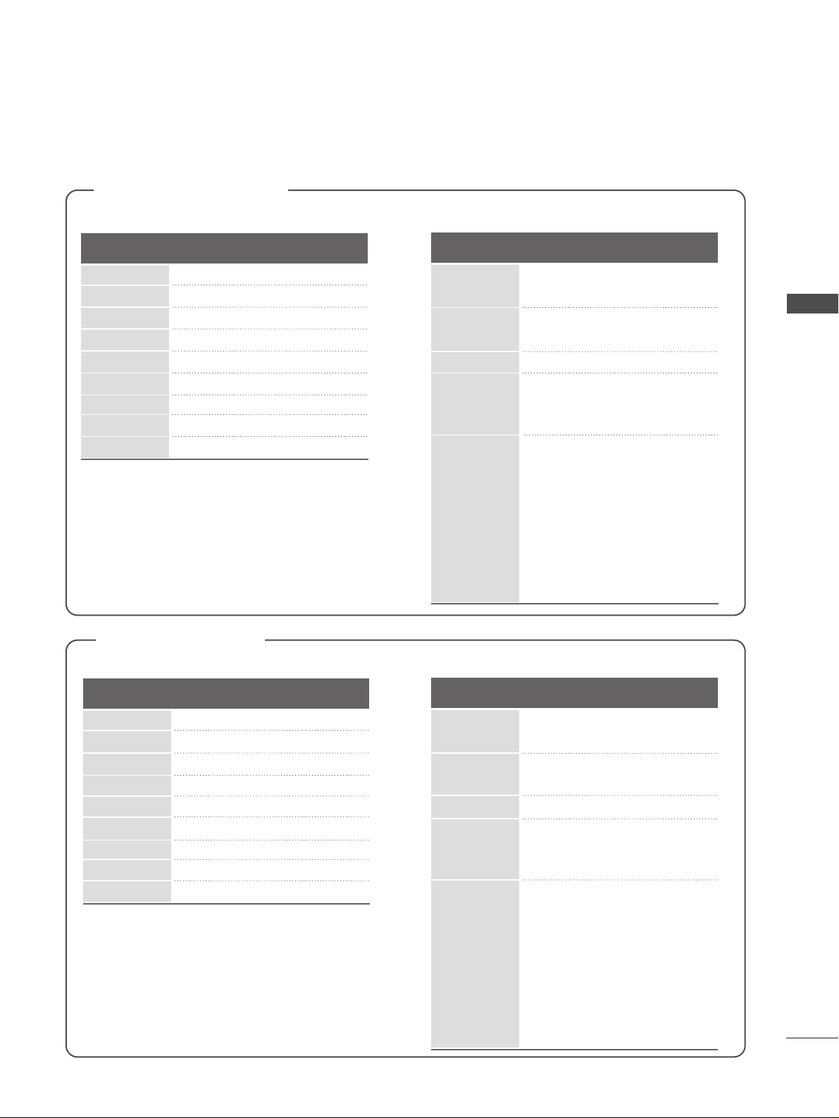
DVI-PC OUTPUT
AUDIO
Connecting with a HDMI to DVI cable
1 2
26
EXTERNAL EQIPMENT SETUP
EXTERNAL EQUIPMENT SETUP
4
Connect the DVI output of the PC to the
HHDDMMII// DDVV II
II NN11
jack on the TV.
Connect the PC audio output to the
AAUU DDIIOO IINN
((RRGGBB // DDVV II))
jack on the TV.
Turn on the PC and the TV.
Select
HH DD MMII11
input source using the INPUT button
on the remote control.
2
3
1
27
EXTERNAL EQUIPMENT SETUP
Supported Display Resolution
RGB-PC, HDMI/DVI-PC mode
70.08
59.94
60.31
60.00
59.87
59.80
59.934
60.02
59.979
31.468
31.469
37. 879
48.363
47. 78
47. 72
66.587
63.98
65.317
720x400
640x480
800x600
1024x768
1280x768
1360x768
1920x1080
1280x1024
1400x1050
Resolution
Horizontal
Frequency(kHz)
Vertical
Frequency(Hz)
HDMI/DVI-DTV mode
59.94
60
59.94
60
50.00
50.00
59.94
60
50.00
59.94
60
24.00
30
50.00
59.94
60
31.649
31.469
31.47
31.50
31.25
37. 50
44.96
45.00
28.125
33.72
33.75
27.00
33.750
56.25
67. 433
67. 50
Resolution
Horizontal
Frequency(kHz)
Vertical
Frequency(Hz)
640x480
720x480
720x576
1280x720
1920x1080
Plasma TV Models
RGB-PC, HDMI/DVI-PC mode
70.08
59.94
60.31
60.00
59.87
59.80
59.934
60.02
59.979
31.468
31.469
37. 879
48.363
47. 78
47. 72
66.587
63.98
65.317
720x400
640x480
800x600
1024x768
1280x768
1360x768
1920x1080
1280x1024
1400x1050
Resolution
Horizontal
Frequency(kHz)
Vertical
Frequency(Hz)
HDMI/DVI-DTV mode
59.94
60
59.94
60
50.00
50.00
50.94
60
50.00
59.94
60
24.00
30
50.00
59.94
60
31.649
31.469
31.47
31.50
31.25
37. 50
44.96
45.00
28.125
33.72
33.75
27.00
33.750
56.25
67. 433
67. 50
Resolution
Horizontal
Frequency(kHz)
Vertical
Frequency(Hz)
640x480
720x480
720x576
1280x720
1920x1080
LCD TV Models

28
EXTERNAL EQIPMENT SETUP
EXTERNAL EQUIPMENT SETUP
NOTE
!
G
To enjoy vivid picture and sound, connect a PC to
the TV.
G
Avoid keeping a fixed image on the set’s screen
for prolonged periods of time. The fixed image
may become permanently imprinted on the
screen; use a screen saver when possible.
G
Connect the PC to the RGB (PC) or HDMI IN (or
HDMI/DVI IN) port of the TV; change the resolution.
G
There may be interference relating to resolution,
vertical pattern, contrast or brightness in PC
mode. Change the PC mode to another resolution or change the refresh rate to another rate or
adjust the brightness and contrast on the menu
until the picture is clear. If the refresh rate of the
PC graphic card can not be changed, change the
PC graphic card or consult the manufacturer of
the PC graphic card.
G
The synchronization input waveform for
Horizontal and Vertical frequencies are separate.
G
Connect the signal cable from the monitor output port of the PC to the RGB (PC) port of the
TV or the signal cable from the HDMI output
port of the PC to the HDMI IN (or HDMI/DVI
IN) port on the TV.
G
Connect the audio cable from the PC to the
Audio input on the TV. (Audio cables are not
included with the TV).
G
If using a sound card, adjust PC sound as
required.
G
This TV uses a VESA Plug and Play Solution. The
TV provides EDID data to the PC system with a
DDC protocol. The PC adjusts automatically
when using this TV.
G
DDC protocol is preset for RGB (Analog RGB),
HDMI (Digital RGB) mode.
G
If required, adjust the settings for Plug and Play
functionality
G
If the graphic card on the PC does not output
analogue and digital RGB simultaneously, connect
only one of either RGB or HDMI IN (or
HDMI/DVI IN) to display the PC output on the
TV.
G
If graphic card on the PC does output analog and
digital RGB simultaneously, set the TV to either
RGB or HDMI; (the other mode is set to Plug and
Play automatically by the TV.)
G
DOS mode may not work depending on the video
card if you use a HDMI to DVI cable.
G
If you use too long an RGB-PC cable, there may
be interference on the screen. We recommend
using under 5m of cable. This provides the best
picture quality.
G
If connected HDMI(1080p, over 12bit) to HDMI
jack on the side, screen may abnormal.
 Loading...