

LG 52LB9DFUA Users manual

Test Report No.: GETEC-E3-07-067
FCC Class B Certification
APPENDIX H
: USER’S MANUAL
EUT Type: LCD TV/Monitor
FCC ID: BEJ52LB9DFUA

Please read this manual carefully before operating
your set.
Retain it for future reference.
Record model number and serial number of the set.
See the label attached on the back cover and quote
this information to your dealer
when you require service.
LCD TV
OWNER’S MANUAL
LCD TV MODELS
42LBX
47LBX
52LBX
www.lgusa.com / www.lg.ca
As an ENERGY STAR
Partner LGE U. S. A.,Inc.
has determined that this
product meets the
ENERGY STAR guidelines
for energy efficiency.
ENERGY STAR is a set of power-saving
guidelines issued by the U.S.
Environmental Protection Agency(EPA).
WARNING / CAUTION
1
WARNING / CAUTION
To prevent fire or shock hazards, do not expose
this product to rain or moisture.
FCC NOTICE
Class B digital device
This equipment has been tested and found to comply with the limits for a Class B digital device, pursuant to Part 15 of the FCC Rules. These limits are
designed to provide reasonable protection against
harmful interference in a residential installation. This
equipment generates, uses and can radiate radio frequency energy and, if not installed and used in
accordance with the instructions, may cause harmful
interference to radio communications. However,
there is no guarantee that interference will not
occur in a particular installation. If this equipment
does cause harmful interference to radio or television reception, which can be determined by turning
the equipment off and on, the user is encouraged to
try to correct the interference by one or more of
the following measures:
- Reorient or relocate the receiving antenna.
- Increase the separation between the equipment
and receiver.
- Connect the equipment to an outlet on a circuit
different from that to which the receiver is connected.
- Consult the dealer or an experienced radio/TV
technician for help.
Any changes or modifications not expressly
approved by the party responsible for compliance
could void the user’s authority to operate the
equipment.
CAUTION
Do not attempt to modify this product in any way
without written authorization from LG Electronics.
Unauthorized modification could void the user’s
authority to operate this product
The lightning flash with arrowhead
symbol, within an equilateral triangle,
is intended to alert the user to the
presence of uninsulated “dangerous voltage”
within the product’s enclosure that may be of
sufficient magnitude to constitute a risk of electric shock to persons.
The exclamation point within an equi-
lateral triangle is intended to alert the
user to the presence of important
operating and maintenance (servicing) instructions in the literature accompanying the
appliance.
TO REDUCE THE RISK OF ELECTRIC SHOCK
DO NOT REMOVE COVER (OR BACK). NO
USER SERVICEABLE PARTS INSIDE. REFER TO
QUALIFIED SERVICE PERSONNEL.
WARNING/CAUTION
TO REDUCE THE RISK OF FIRE AND ELECTRIC
SHOCK, DO NOT EXPOSE THIS PRODUCT TO
RAIN OR MOISTURE.
NOTE TO CABLE/TV INSTALLER
This reminder is provided to call the CATV system
installer’s attention to Article 820-40 of the National
Electric Code (U.S.A.). The code provides guidelines for
proper grounding and, in particular, specifies that the
cable ground shall be connected to the grounding system
of the building, as close to the point of the cable entry
as practical.
IMPORTANT SAFETY INSTRUCTIONS
SAFETY INSTRUCTIONS
2
Important safety instructions shall be provided with each apparatus. This information shall be given in a separate
booklet or sheet, or be located before any operating instructions in an instruction for installation for use and
supplied with the apparatus.
This information shall be given in a language acceptable to the country where the apparatus is intended to be used.
The important safety instructions shall be entitled “Important Safety Instructions”. The following safety
instructions shall be included where applicable, and, when used, shall be verbatim as follows. Additional safety
information may be included by adding statements after the end of the following safety instruction list. At the
manufacturer’s option, a picture or drawing that illustrates the intent of a specific safety instruction may be
placed immediately adjacent to that safety instruction:
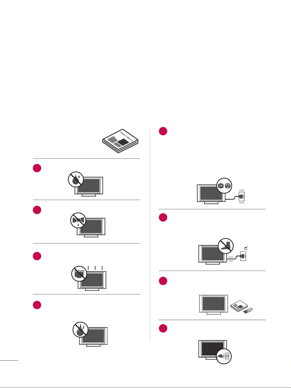
Read these instructions.
Keep these instructions.
Heed all warnings.
Follow all instructions.
Do not use this apparatus near water.
Clean only with dry cloth.
Do not block any ventilation openings. Install in
accordance with the manufacturer’s instructions.
Do not install near any heat sources such as
radiators, heat registers, stoves, or other apparatus
(including amplifiers)that produce heat.
Do not defeat the safety purpose of the polarized
or grounding-type plug. A polarized plug has
two blades with one wider than the other. A
grounding type plug has two blades and a third
grounding prong, The wide blade or the third
prong are provided for your safety. If the provided
plug does not fit into your outlet, consult an
electrician for replacement of the obsolete outlet.
Protect the power cord from being walked on
or pinched particularly at plugs, convenience
receptacles, and the point where they exit from
the apparatus.
Only use attachments/accessories specified by
the manufacturer.
Unplug this apparatus when unused for long
periods of time.
Owner Manual
Owner Manual
Owner Manual
Owner Manual
Owner Manual
Owner Manual
Owner Manual
Owner Manual
Owner Manual
O
w
n
e
r M
a
n
u
a
l
Owner Manual
1
2
3
4
5
6
7
8
Owner Manual
3
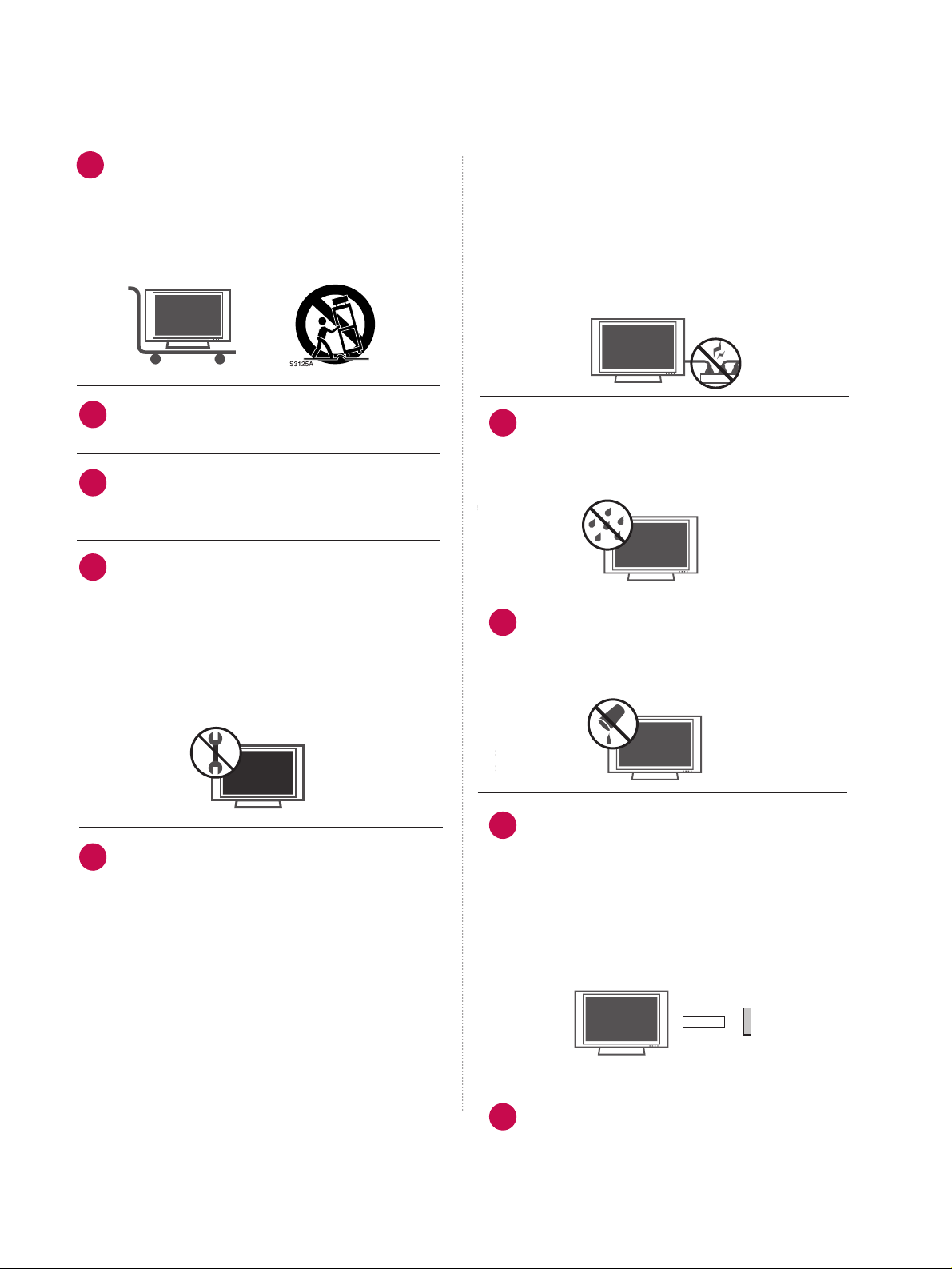
Use only with the cart, stand, tripod, bracket,
or table specified by the manufacturer, or sold
with the apparatus. When a cart is used, use
caution when moving the cart/apparatus
combination to avoid injury from tip-over.
Never touch this apparatus or antenna during
a thunder or lighting storm.
Do not allow a impact shock or any objects to
fall into the product, and do not drop onto the
screen with something.
Refer all servicing to qualified service personnel.
Servicing is required when the apparatus has
been damaged in any way, such as power-supply
cord or plug is damaged, liquid has been
spilled or objects have fallen into the apparatus,
the apparatus has exposed to rain or moisture,
does not operate normally, or has been
dropped.
CAUTION concerning the Power Cord :
Most appliances recommend they be placed
upon a dedicated circuit; that is, a single outlet
circuit which powers only that appliance and
has no additional outlets or branch circuits.
Check the specification page of this owner's
manual to be certain.
Do not overload wall outlets. Overloaded wall
outlets, loose or damaged wall outlets, extension
cords, frayed power cords, or damaged or
cracked wire insulation are dangerous. Any of
these conditions could result in electric shock
or fire. Periodically examine the cord of your
appliance, and if its appearance indicates damage or deterioration, unplug it, discontinue use
of the appliance, and have the cord replaced
with an exact replacement part by an authorized
servicer. Protect the power cord from physical
or mechanical abuse, such as being twisted,
kinked, pinched, closed in a door, or walked
upon. Pay particular attention to plugs, wall
outlets, and the point where the cord exits the
appliance.
Outdoor use marking :
WARNING - To reduce the risk of fire or elec-
tric shock, do not expose this appliance to rain
or moisture.
Wet Location Marking : Apparatus shall not be
exposed to dripping or splashing and no
objects filled with liquids, such as vases, shall
be placed on or over apparatus.
GGRROOUU NNDDIINNGG
Ensure that you connect the earth ground wire
to prevent possible electric shock. If grounding
methods are not possible, have a qualified
electrician install a separate circuit breaker.
Do not try to ground the unit by connecting it
to telephone wires, lightening rods, or gas pipes.
DDIISS CCOONNNN EECCTTIINNGG DDEEVVIICC EE FFRR OOMM MMAAIINNSS
Mains plug is the disconnecting device. The
plug must remain readily operable.
Owner Manual
Owner Manual
Owner Manual
Owner Manual
Owner Manual
Owner Manual
9
12
10
11
13
14
15
16
17
Power
Supply
Short-circuit
Breaker

4
CONTENTS
WARNING / CAUTION
. . . . . . . . . . . . . . . . . . . . . . . . . . . . 1
SAFETY INSTRUCTIONS
. . . . . . . . . . . . . . . . . . . . . . . . . . 2
FEATURE OF THIS TV
. . . . . . . . . . . . . . . . . . . . . . . . . . . . . . . 6
PREPARATION
Accessories
. . . . . . . . . . . . . . . . . . . . . . . . . . . . . . . . . . . . . . . . . . . . . . . . . . . . . . 7
Front Panel Information
. . . . . . . . . . . . . . . . . . . . . . . . . . . . . . . . . . . . . 8
Back Panel Information . . . . . . . . . . . . . . . . . . . . . . . . . . . . . . . . . . . . . . 9
Attaching the TV to a Wall
. . . . . . . . . . . . . . . . . . . . . . . . . . . . . . . 10
Back Cover for Wire Arrangement . . . . . . . . . . . . . . . . . . . . . 11
Desktop Pedestal Installation
. . . . . . . . . . . . . . . . . . . . . . . . . . . . 12
VESA Wall Mounting
. . . . . . . . . . . . . . . . . . . . . . . . . . . . . . . . . . . . . . . . 12
Antenna or Cable Connection
. . . . . . . . . . . . . . . . . . . . . . . . . . 13
EXTERNAL EQUIPMENT SETUP
HD Receiver Setup . . . . . . . . . . . . . . . . . . . . . . . . . . . . . . . . . . . . . . . . . 14
DVD Setup
. . . . . . . . . . . . . . . . . . . . . . . . . . . . . . . . . . . . . . . . . . . . . . . . . . . . . .
17
VCR Setup
. . . . . . . . . . . . . . . . . . . . . . . . . . . . . . . . . . . . . . . . . . . . . . . . . . . . . 19
PC Setup
. . . . . . . . . . . . . . . . . . . . . . . . . . . . . . . . . . . . . . . . . . . . . . . . . . . . . . . .21
Other A/V Source Setup
. . . . . . . . . . . . . . . . . . . . . . . . . . . . . . . . .26
USB In Setup . . . . . . . . . . . . . . . . . . . . . . . . . . . . . . . . . . . . . . . . . . . . . . . . . 26
Audio Out Setup
. . . . . . . . . . . . . . . . . . . . . . . . . . . . . . . . . . . . . . . . . . . .27
WATCHING TV / CHANNEL CONTROL
Remote Control Key Functions . . . . . . . . . . . . . . . . . . . . . . . . .28
Turning On TV . . . . . . . . . . . . . . . . . . . . . . . . . . . . . . . . . . . . . . . . . . . . . . . . 30
Channel Selection
. . . . . . . . . . . . . . . . . . . . . . . . . . . . . . . . . . . . . . . . . . . 30
Volume Adjustment . . . . . . . . . . . . . . . . . . . . . . . . . . . . . . . . . . . . . . . . . 30
On-Screen Menus Selection
. . . . . . . . . . . . . . . . . . . . . . . . . . . . . 31
Channel Setup
- Auto Scan (Auto Tuning)
. . . . . . . . . . . . . . . . . . . . . . . . . . . 32
- Add / Delete Channel (Manual Tuning)
. . . . . . 33
- Channel Editing . . . . . . . . . . . . . . . . . . . . . . . . . . . . . . . . . . . . . . . . 34
Input List
. . . . . . . . . . . . . . . . . . . . . . . . . . . . . . . . . . . . . . . . . . . . . . . . . . . . . . . .35
SimpLink . . . . . . . . . . . . . . . . . . . . . . . . . . . . . . . . . . . . . . . . . . . . . . . . . . . . . . . . . 36
Input Label . . . . . . . . . . . . . . . . . . . . . . . . . . . . . . . . . . . . . . . . . . . . . . . . . . . . . 38
Entry Modes
. . . . . . . . . . . . . . . . . . . . . . . . . . . . . . . . . . . . . . . . . . . . . . . . . . . 39
Photo List
. . . . . . . . . . . . . . . . . . . . . . . . . . . . . . . . . . . . . . . . . . . . . . . . . . . . . . .40
Music List
. . . . . . . . . . . . . . . . . . . . . . . . . . . . . . . . . . . . . . . . . . . . . . . . . . . . . . .44
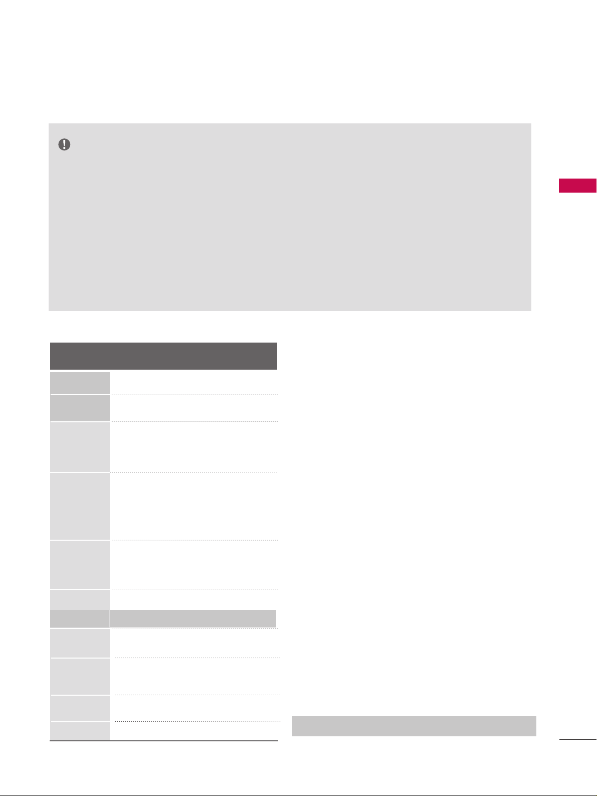
PICTURE CONTROL
Picture Size (Aspect Ratio) Control
. . . . . . . . . . . . . . . . . . 46
Preset Picture Settings
- Picture Mode - Preset
. . . . . . . . . . . . . . . . . . . . . . . . . . . . . . . 47
- Color Tone - Preset
. . . . . . . . . . . . . . . . . . . . . . . . . . . . . . . . . . 48
Manual Picture Adjustment
- Picture Mode - User Mode
. . . . . . . . . . . . . . . . . . . . . . . . 49
- Color Tone - User Mode
. . . . . . . . . . . . . . . . . . . . . . . . . . . 50
XD - Picture Improvement Technology
. . . . . . . . . . . . . 51
Advanced - Cinema 3:2 Pulldown Mode
. . . . . . . . . . .52
Advanced - Black (Darkness) Level
. . . . . . . . . . . . . . . . . . . 53
Advanced - TruM
. . . . . . . . . . . . . . . . . . . . . . . . . . . . . . . . . . . . . . . . . . . .54
TruM Demo
. . . . . . . . . . . . . . . . . . . . . . . . . . . . . . . . . . . . . . . . . . . . . . . . . . . . 55
Picture Reset
. . . . . . . . . . . . . . . . . . . . . . . . . . . . . . . . . . . . . . . . . . . . . . . . . 56
SOUND & LANGUAGE CONTROL
Auto Volume Leveller (Auto Volume)
. . . . . . . . . . . . . . . . 57
Preset Sound Setting (Sound Mode)
. . . . . . . . . . . . . . . . 58
Sound Setting Adjustment - User Mode
. . . . . . . . . . .59
Balance
. . . . . . . . . . . . . . . . . . . . . . . . . . . . . . . . . . . . . . . . . . . . . . . . . . . . . . . . . . 60
Stereo/SAP Broadcasts Setup
. . . . . . . . . . . . . . . . . . . . . . . . . . 61
TV Speakers On/Off Setup
. . . . . . . . . . . . . . . . . . . . . . . . . . . . . . 62
Audio Language
. . . . . . . . . . . . . . . . . . . . . . . . . . . . . . . . . . . . . . . . . . . . . . 63
On-Screen Menus Language Selection
. . . . . . . . . . . . . 64
Caption Mode
. . . . . . . . . . . . . . . . . . . . . . . . . . . . . . . . . . . . . . . . . . . . . . . . 65
- Analog Broadcasting System Captions
. . . . . . . 66
- Digital Broadcasting System Captions
. . . . . . . . 67
- Caption Option
. . . . . . . . . . . . . . . . . . . . . . . . . . . . . . . . . . . . . . .68
MEDIAMEDIAMEDIA
HOST HOST HOST
MEDIA
HOST

5
TIME SETTING
Clock Setting
- Auto Clock Setup
. . . . . . . . . . . . . . . . . . . . . . . . . . . . . . . . . . . . 69
- Manual Clock Setup
. . . . . . . . . . . . . . . . . . . . . . . . . . . . . . . . .70
Auto On/Off Timer Setting . . . . . . . . . . . . . . . . . . . . . . . . . . . . . 71
Sleep Timer Setting
. . . . . . . . . . . . . . . . . . . . . . . . . . . . . . . . . . . . . . . . .
72
Auto Shut-off Setting . . . . . . . . . . . . . . . . . . . . . . . . . . . . . . . . . . . . . . .
73
PARENTAL CONTROL / RATINGS
Set Password & Lock System
. . . . . . . . . . . . . . . . . . . . . . . . . . . 74
Channel Blocking
. . . . . . . . . . . . . . . . . . . . . . . . . . . . . . . . . . . . . . . . . . . .76
Movie & TV Rating
. . . . . . . . . . . . . . . . . . . . . . . . . . . . . . . . . . . . . . . . . . 77
External Input Blocking
. . . . . . . . . . . . . . . . . . . . . . . . . . . . . . . . . . . . 80
Key Lock
. . . . . . . . . . . . . . . . . . . . . . . . . . . . . . . . . . . . . . . . . . . . . . . . . . . . . . . . .
80
APPENDIX
Troubleshooting . . . . . . . . . . . . . . . . . . . . . . . . . . . . . . . . . . . . . . . . . . . . . . 81
Maintenance
. . . . . . . . . . . . . . . . . . . . . . . . . . . . . . . . . . . . . . . . . . . . . . . . . . . 83
Product Specifications
. . . . . . . . . . . . . . . . . . . . . . . . . . . . . . . . . . . . . 84
Programming the Remote Control
. . . . . . . . . . . . . . . . . . . 85
IR Codes
. . . . . . . . . . . . . . . . . . . . . . . . . . . . . . . . . . . . . . . . . . . . . . . . . . . . . . .89
External Control Through RS-232C
. . . . . . . . . . . . . . . . . .91
PREPARATION
FEATURES OF THIS TV
6
■ If the TV feels cold to the touch, there may be a small “flicker” when it is turned on. This is normal, there is noth-
ing wrong with TV.
■ Some minute dot defects may be visible on the screen, appearing as tiny red, green, or blue spots. However, they
have no adverse effect on the monitor's performance.
■ Avoid touching the LCD screen or holding your finger(s) against it for long periods of time. Doing so may pro-
duce some temporary distortion effects on the screen.
OOnn DDii sspp oo ssaall
a. The fluorescent lamp used in this product contains a small amount of mercury.
b. Do not dispose of this product with general household waste.
c. Disposal of this product must be carried out in accordance to the regulations of your local authority.
is a trademark of SRS Labs, Inc.
TruSurround XT technology is incorporated under
license from SRS Labs, Inc.
LG TV with this logo displays Full HD(high-definition) 1080p native resolution by receiving and processing a Full HD 1080p signal.
LG TV with this logo can play MP3 music from a
MP3 player, such as iPOD, and JPEG images from a
digital camera through the USB device.
With HDMI CEC support of LG’s audio/video device
connected to the HDMI (high-definition multimedia
interface), LG TV with this logo works easily with one
remote control.
It has three HDMI ports that connect audio and
video devices with one cable and produces the highest quality digital images and sound.
?
R
TruSurround XT
Manufactured under license from Dolby Laboratories.
“
Dolby
“and the double-D symbol are trademarks of
Dolby Laboratories.
High-definition television. High-resolution digital
television broadcast and playback system composed
of roughly a million or more pixels, 16:9 aspect-ratio
screens, and AC3 digital audio. A subset of digital
television, HDTV formats include 1080i and 720p
resolutions.
LG's own special digital image generator, consisting
of a full digital image processor, six different main
picture quality factors.
?
?
R
TruSurround XT
PREPARATION
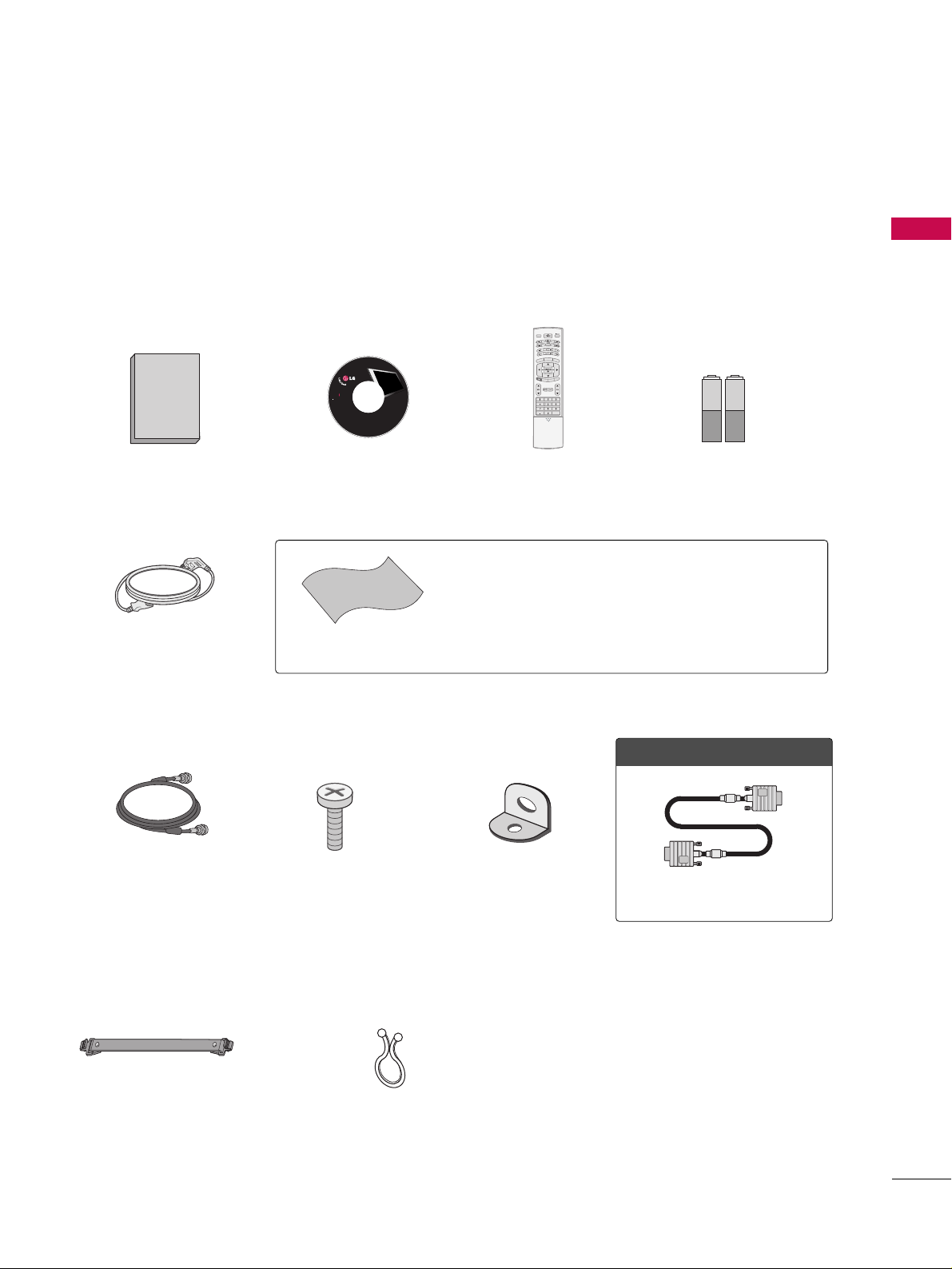
ACCESSORIES
7
Owner's Manual
1.5V
1.5V
Owner’s Manual
Batteries
75ohm Round Cable
Remote Control
Cable Management
2- TV Bracket Bolts
2- TV Brackets,
2- Wall Brackets
Ensure that the following accessories are included with your plasma display. If an accessory is missing, please
contact the dealer where you purchased the product.
User must use shielded signal interface cables (D-sub 15 pin cable) with ferrite cores to maintain standard
compliance for the product.
TV INPUT
STB
BACK
■
Slightly wipe stained spot on the exterior only with the polishing
cloth for the product exterior if there is stain or fingerprint on
surface of the exterior.
■
Do not wipe roughly when removing stain. Please be cautions of
that excessive power may cause scratch or discoloration.
Polishing Cloth
OOppttiioonn EExxttrraass
D-sub 15 pin Cable
Power Cord
CD Manual
LCD TV PLASMA TV
Owner's Manual
http://www.lgusa.com
www.lg.ca
Copyright© 2007 LGE,
All Rights Reserved.
PREPARATION
Twist Holder
Arrange the wires with the
twist holder.
TV INPUT
STB
MENU
BR
IG
-
T
H
H
T
+
RIG
B
K
N
LI
P
SIM
T
IMER
RATIO
BACK
APM
M/C EJECT
AUTO DEMO
CC
PREPARATION
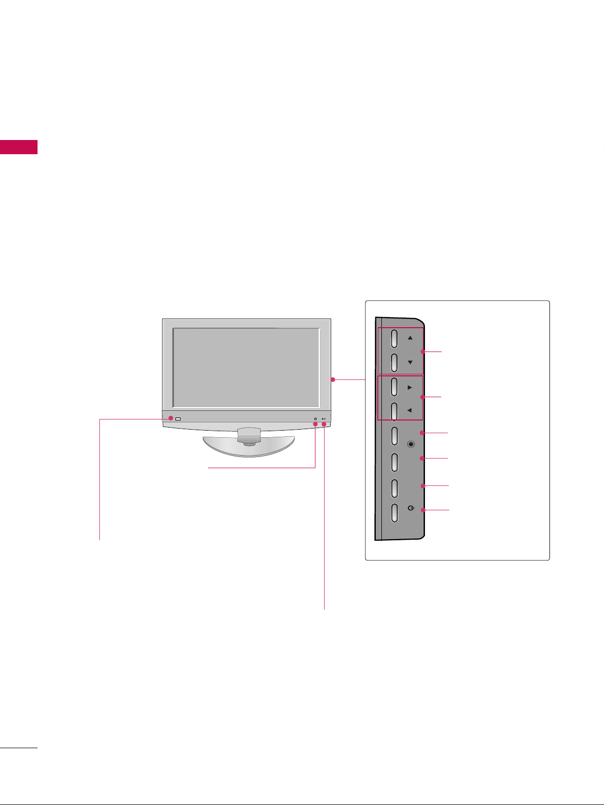
FRONT PANEL INFORMATION
PREPARATION
8
CH
VOL
CH
VOL
CHANNEL
(
DD,EE
) Buttons
VOLUME
(
FF,GG
) Buttons
ENTER Button
MENU Button
INPUT Button
POWER Button
Remote Control Sensor
Intelligent Eye
Adjusts picture according to
the surrounding conditions.
Power/Standby Indicator
• Illuminates red in standby mode.
• Illuminates green when the set is switched on.
■
Here shown may be somewhat different from your TV.
■
NOTE: If your product has a protection tape attached, remove the tape.
And then wipe the product with a cloth (If a polishing cloth is included with your product, use it).
CH
VOL
ENTER
MENU
INPUT
/I
PREPARATION
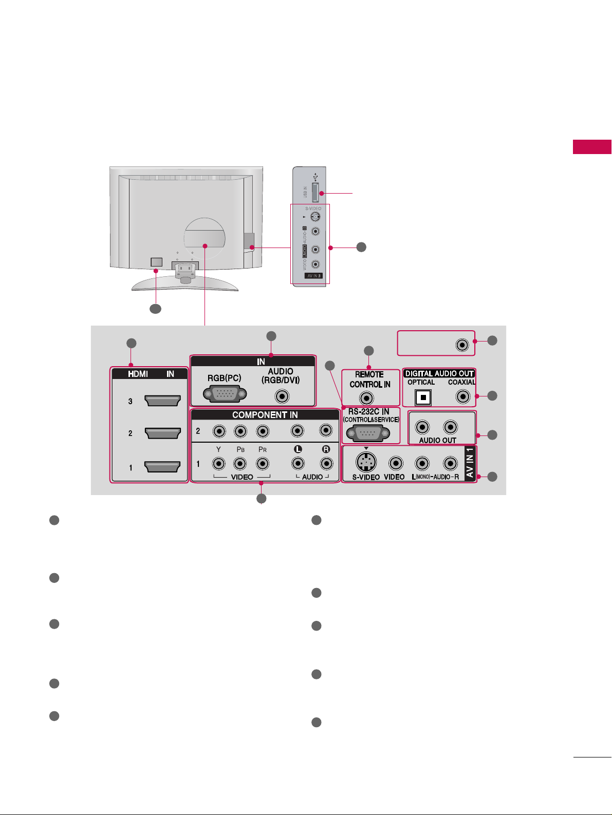
BACK PANEL INFORMATION
9
■
Here shown may be somewhat different from your TV.
S-VIDEO
USB Input port
10
AV IN 2
L/ MONO
R
AUDIO
VIDEO
S-VIDEO
USB IN
RGB
/DVI
ANTENNA/ANTENNA/
CABLE INABLE IN
1
3
2
4
5
9
8
7
6
HDMI/DVI IN
Connect a HDMI signal to 1, 2 or 3.
Or DVI (VIDEO)signal to the 1, 2 or 3 port with a
DVI to HDMI cable.
COMPONENT IN
Connect a component video/audio device to these
jacks.
RGB(PC)
AUDIO (RGB/DVI)
Connect the monitor output from a PC to the
appropriate input port.
RS-232C IN (CONTROL & SERVICE) PORT
Connect to the RS-232C port on a PC.
REMOTE CONTROL PORT
Connect your wired remote control.
AV (Audio/Video) IN 1
Connect audio/video output from an external
device to these jacks.
S-VIDEO
Connect S-Video out from an S-VIDEO device.
AUDIO OUT
Connect analog audio to various types of equipment.
DIGITAL AUDIO OUT
Connect digital audio to various types of equipment.
Note: In standby mode, these ports do not work.
ANTENNA/CABLE IN
Connect over-the air signals to this jack.
Connect cable signals to this jack.
Power Cord Socket
For operation with AC power.
Caution: Never attempt to operate the TV on DC power.
1
7
6
8
9
2
3
4
5
10
6
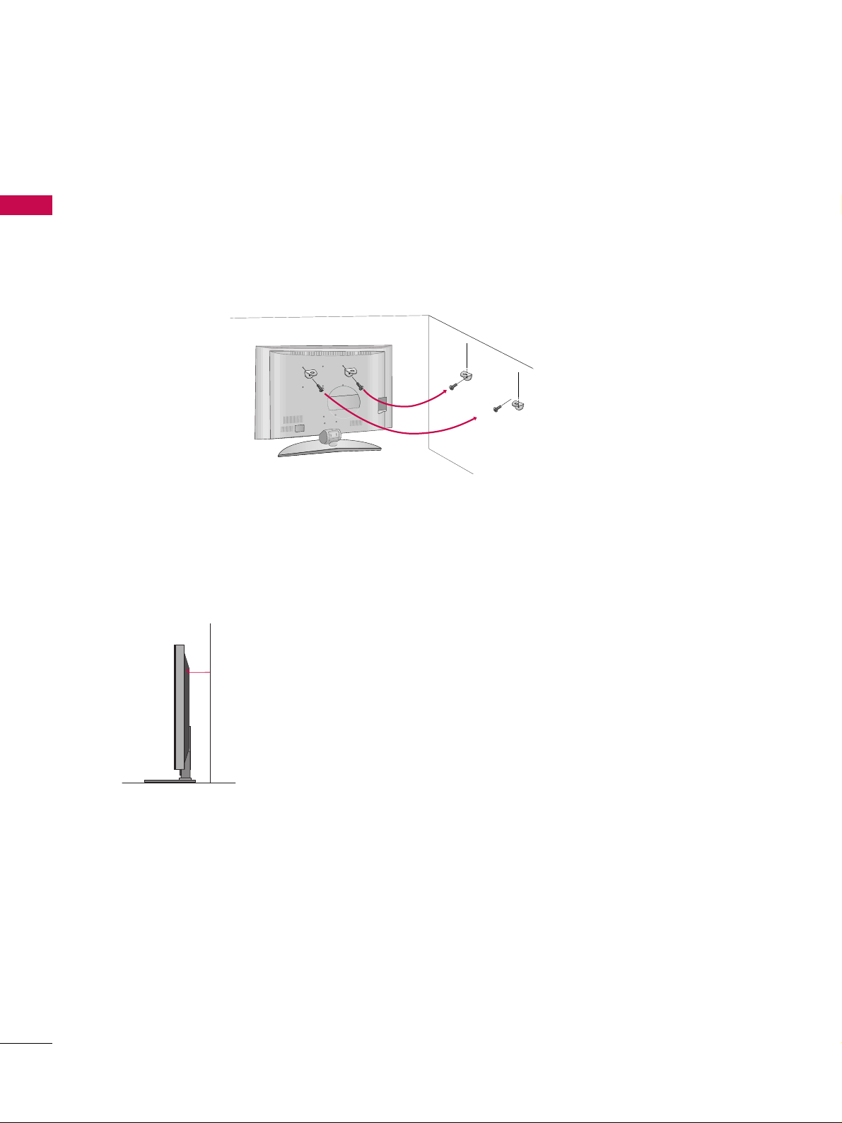
PREPARATION
ATTACHING THE TV TO A WALL
PREPARATION
10
We recommend that you set up the TV close to a wall so it cannot fall over if pushed backwards.
Additionally, we recommend that the TV be attached to a wall so it cannot be pulled in a forward direction,
potentially causing injury or damaging the product.
Caution: Please make sure that children don’t climb on or hang from the TV.
■
Insert the eye-bolts (or TV brackets and bolts) to tighten the product to the wall as shown in the picture.
*Insert the eye-bolts and tighten them securely in the upper holes.
Secure the wall brackets with the bolts (not provided as parts of the product, must purchase separately ) to
the wall. Match the height of the bracket that is mounted on the wall to the holes in the product.
Ensure the eye-bolts or brackets are tightened securely.
■
Use a sturdy rope (not provided as parts of the product, must purchase
separately) to tie the product. It is safer to tie the rope so it becomes horizontal
between the wall and the product.
■
Here shown may be somewhat different from your TV.
PREPARATION
BACK COVER FOR WIRE ARRANGEMENT
11
■
Here shown may be somewhat different from your TV.
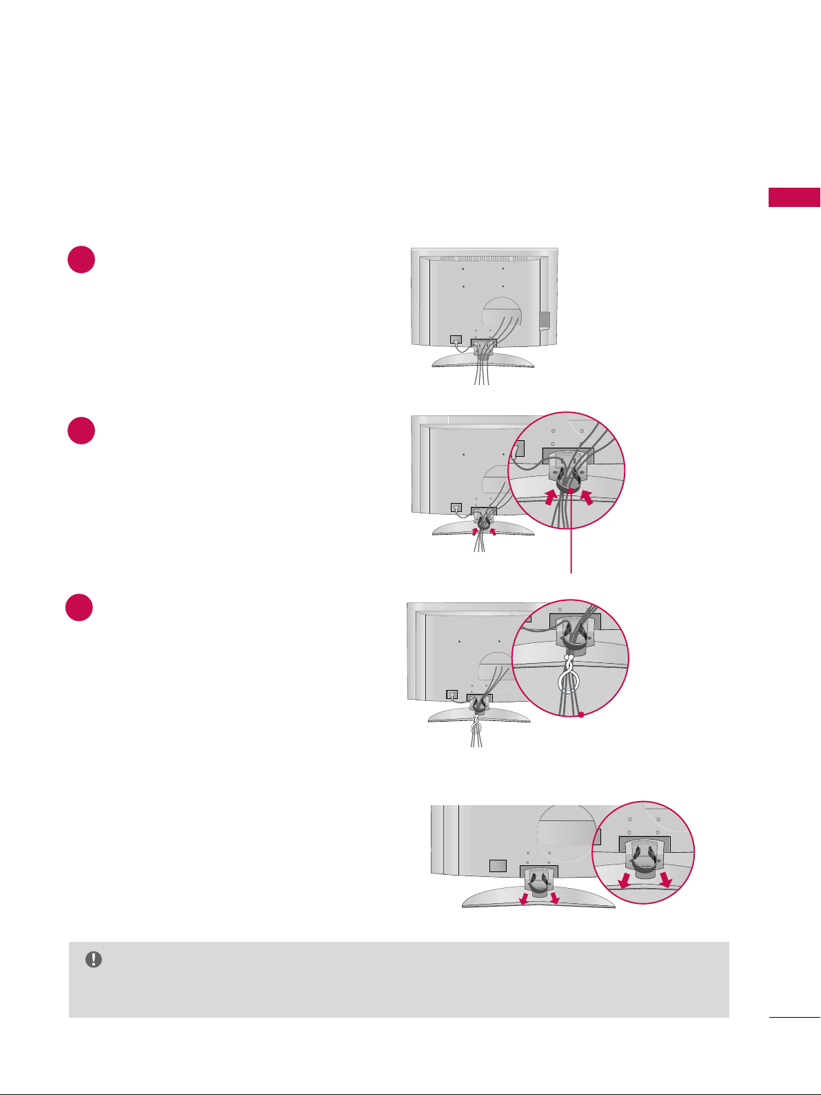
Connect the cables as necessary.
To connect an additional equipment, see the
EExxtteerrnnaall eeqquuiippmmeenntt CCoonnnneeccttiioonnss
section.
Install the
CCAABBLLEE MMAANNAA GGEEMMEE NN TT
as shown.
(Insert it as pushing the loops on the both
sides of the cable management.)
Bundle the cables using the supplied twist
holder.
Hold the
CC AABBLL EE MMAANNAAGG EEMMEENNTT
with both
hands and pull it out.
(Pull it out as holding the loops on the both sides of
the cable management.)
NOTE
GG
Do not hold the CABLE MANAGEMENT when moving the product.
- If the product is dropped, you may be injured or the product may be broken.
How to remove the cable management
CABLE MANAGEMENT
1
2
3
PREPARATION
DESKTOP PEDESTAL INSTALLATION
PREPARATION
12
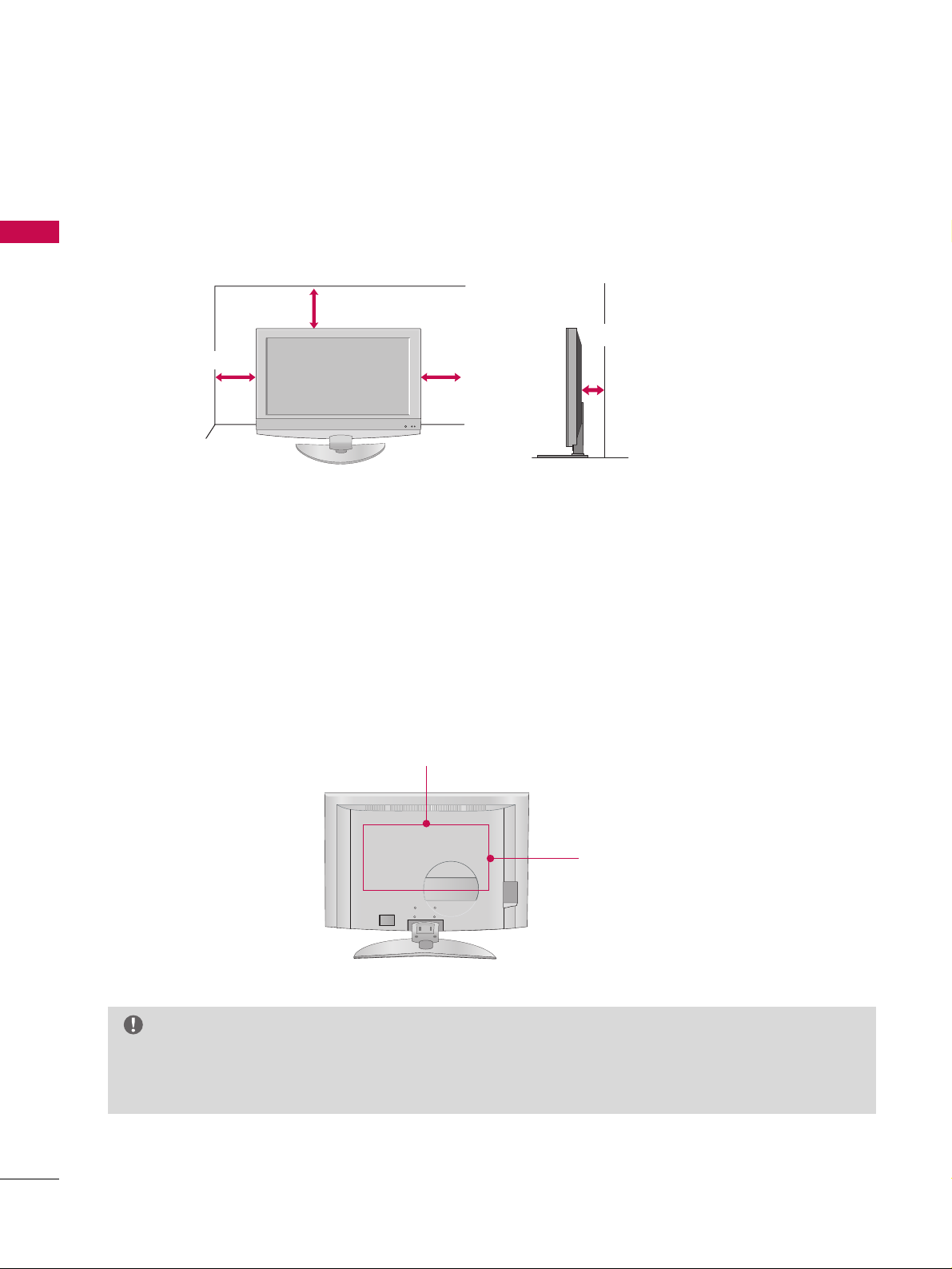
For proper ventilation, allow a clearance of 4inches on all four sides from the wall.
VESA WALL MOUNTING
This product accepts a VESA-compliant mounting interface pad. (optional)
There 4 threaded holes are available for attaching the bracket.
GG
Screw length needed depends on the wall mount used. For further information, refer to the VESA
Wall Mounting Instruction Guide.
NOTE
4 inches
4 inches
4 inches
4 inches
400mm
600mm
PREPARATION
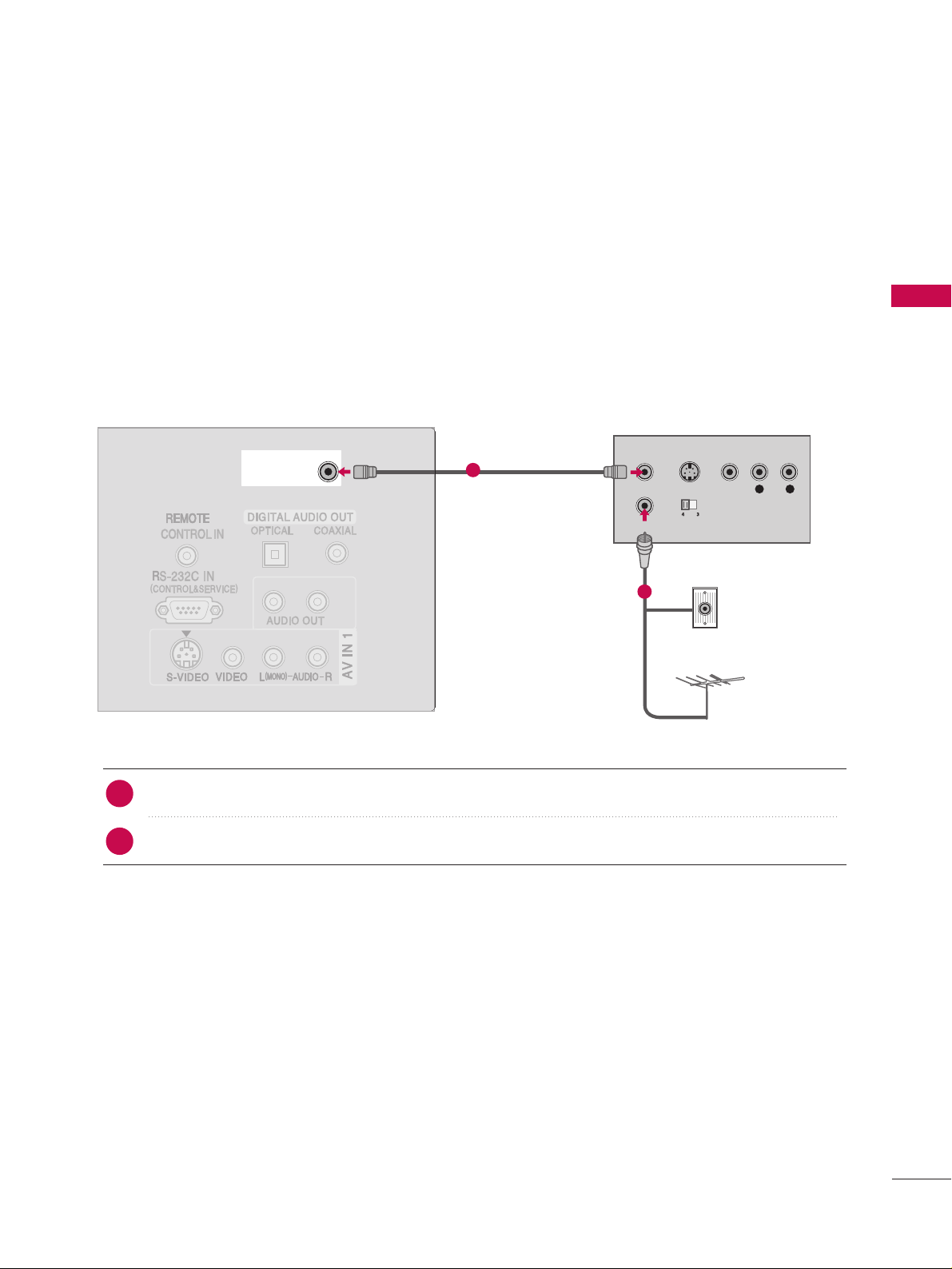
ANTENNA OR CABLE CONNECTION
13
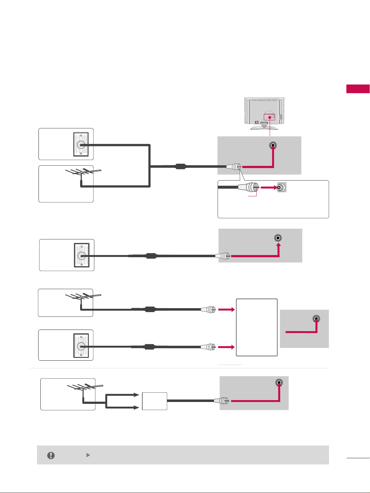
1. Antenna (analog or digital)
Wall Antenna Socket or Outdoor Antenna without a Cable Box
Connections. For optimum picture quality, adjust antenna direction if needed.
2. Cable
ANTENNA/
CABLE IN
ANTENNA/
CABLE IN
Wall
Antenna
Socket
Outdoor
Antenna
(VHF, UHF)
Cable TV
Wall Jack
Multi-family Dwellings/Apartments
(Connect to wall antenna socket)
RF Coaxial Wire (75 ohm)
RF Coaxial Wire (75 ohm)
Single-family Dwellings /Houses
(Connect to wall jack for outdoor antenna)
Be careful not to bend the bronze wire
when connecting the antenna.
Copper Wire
The TV will let you know when the analog, cable, and digital channel scans are complete.
NOTE
ANTENNA/
CABLE IN
■
To improve the picture quality in a poor signal area, please purchase a signal amplifier and install properly.
■
If the antenna needs to be split for two TV’s, install a 2-Way Signal Splitter.
■
If the antenna is not installed properly, contact your dealer for assistance.
Antenna
UHF
Signal
Amplifier
VHF
3. Using both cable and antenna
Cable TV
Wall Jack
Antenna
RF Coaxial Wire (75 ohm)
RF Coaxial Wire (75 ohm)
Diplexer
(Signal
Combinner)
ANTENNA/
CABLE IN
EXTERNAL EQUIPMENT SETUP
14
HD RECEIVER SETUP
EXTERNAL EQUIPMENT SETUP
This TV can receive Digital Over-the-air/Cable signals without an external digital set-top box. However, if you
do receive digital signals from a digital set-top box or other digital external device, refer to the figure as
shown below.
This TV supports HDCP (High-bandwidth Digital Contents Protection)protocol for Digital Contents.
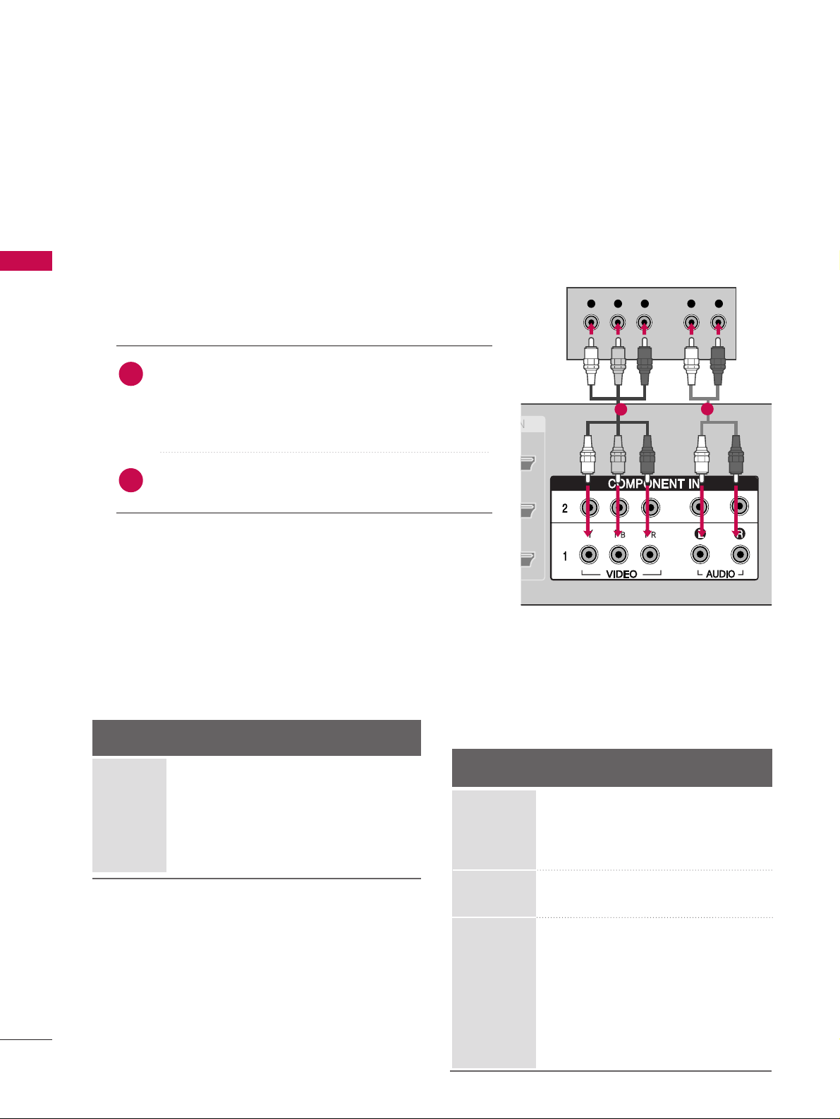
Y L RPB PR
When connecting Component cable
1. How to connect
Connect the video outputs (Y, PB, PR
)
of the digital set
top box to the
CCOOMMPPOONNEENNTT IINN VVIIDDEEOO 11
jacks on
the set. Match the jack colors
(Y = green, P
B = blue, and PR = red).
Connect the audio output of the digital set-top box to
the
CCOOMMPPOONNEENNTT IINN AAUUDDIIOO 11
jacks on the set.
2. How to use
■
Turn on the digital set-top box.
(
Refer to the owner’s manual for the digital set-top box.
)
■
Select
CCoommppoonneenntt 11
input source with using the
IINNPPUUTT
button on the remote control.
■
If connected to
CCOOMMPPOONNEENNTT IINN 22
input, select
CCoommppoonneenntt 22
input source.
Signal
Component 1/2
Yes
Yes
Yes
Yes
Yes
HDMI/DVI1, 2 or 3
No
Yes
Yes
Yes
Yes
2
1
1
2
480i
480p
720p
10 8 0 i
10 8 0 p
Supported Display Specifications (Y, CB /PB,CR /P
R
)
Horizontal Vertical
Frequency(KHz)Frequency(Hz
)
15.73 60.00
15.73 59.94
31.47 59.94
31.47 60.00
45.00 60.00
44.96 59.94
33.75 60.00
33.72 59.94
67.50 60.00
67. 432 59.939
27.00 24.00
26.97 23.94
33.75 30.00
33.71 29.97
Resolution
1280x720
1920x1080
720x480
15
EXTERNAL EQUIPMENT SETUP
(DVI)VI)
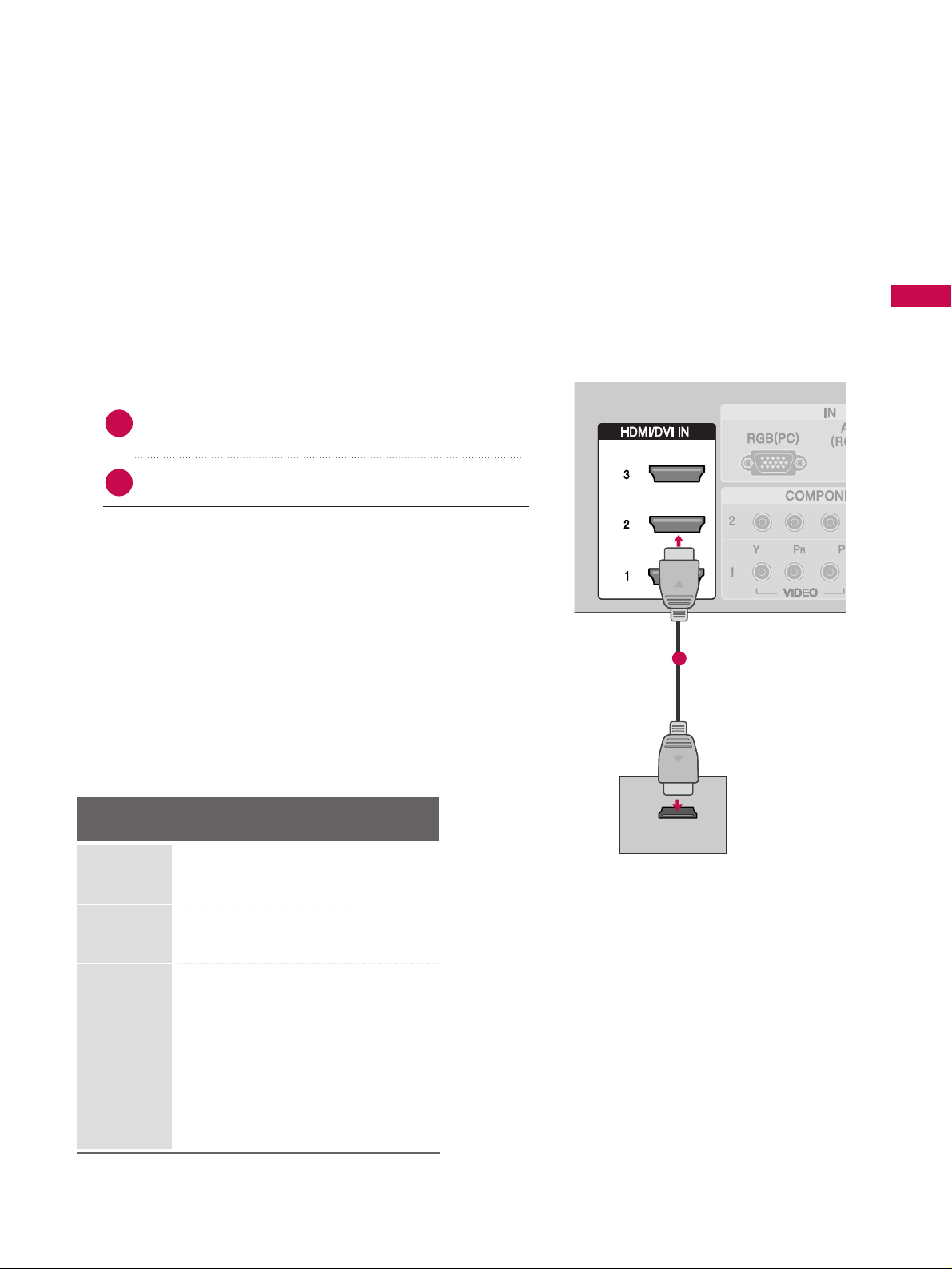
HDMI-DTV OUTPUT
When connecting HDMI cable
Connect the digital set-top box to
HHDDMMII//DD VVII IINN 11
,
22
or
33
jack on the set.
No separated audio connection is necessary.
1. How to connect
2. How to use
■
Turn on the digital set-top box.
(
Refer to the owner’s manual for the digital set-top box.
)
■
Select
HHDDMMII11,HHDDMMII22 orHHDDMMII33
input source with using
the
IINNPPUUTT
button on the remote control.
■
If the digital set-top box player does not support Auto HDMI,
you need to set the output resolution appropriately.
2
1
1
Supported Display Specifications (HDMI-DTV
)
Horizontal Vertical
Frequency(KHz)Frequency(Hz
)
31.47 60.00
31.47 59.94
45.00 60.00
44.96 59.94
33.75 60.00
33.72 59.94
67.50 60.00
67. 432 59.939
27.00 24.00
26.97 23.94
33.75 30.00
33.71 29.97
Resolution
720x480
1280x720
1920x1080
EXTERNAL EQUIPMENT SETUP
EXTERNAL EQUIPMENT SETUP
16
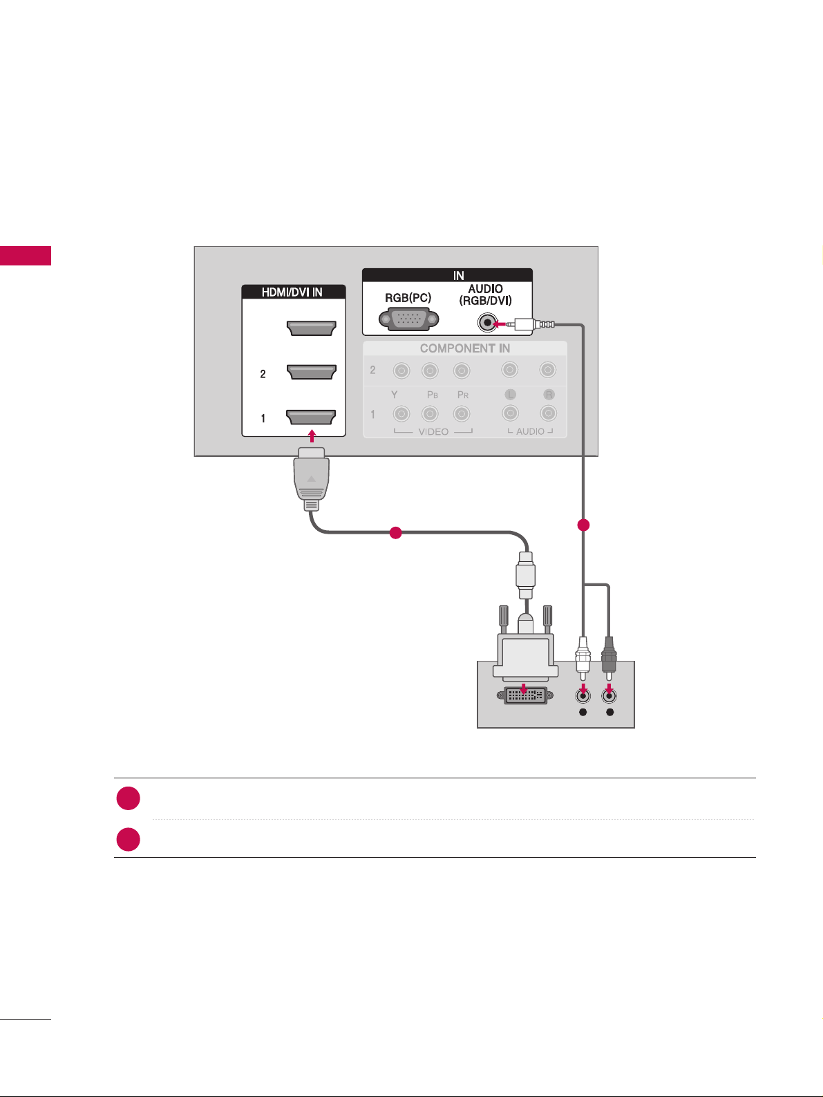
When connecting HDMI to DVI cable
RGB
Connect the DVI output of the digital set-top box to the
HHDDMMII//DD VVII IINN11, 22
or
33
jack on the set.
Connect the audio output of the digital set-top box to the
AAUUDDIIOO((RRGGBB//DDVVII
))
jack on the set.
1. How to connect
■
Turn on the digital set-top box. (Refer to the owner’s manual for the digital set-top box.
)
■
Select
HHDDMMII11,HHDDMMII22 orHHDDMMII33
input source with using the
IINNPPUUTT
button on the remote control.
2. How to use
2
1
1
2
RGB
3
DVI-DTV OUTPUT
L R
EXTERNAL EQUIPMENT SETUP
DVD SETUP
17
Component Input ports
To get better picture quality, connect a DVD player to the component input ports as shown below.
Component ports on the TV
YPB PR
Video output ports
on DVD player
Y
Y
Y
Y
P
B
Pb
B-Y
Cb
P
R
Pr
R-Y
Cr
Y L RPB PR
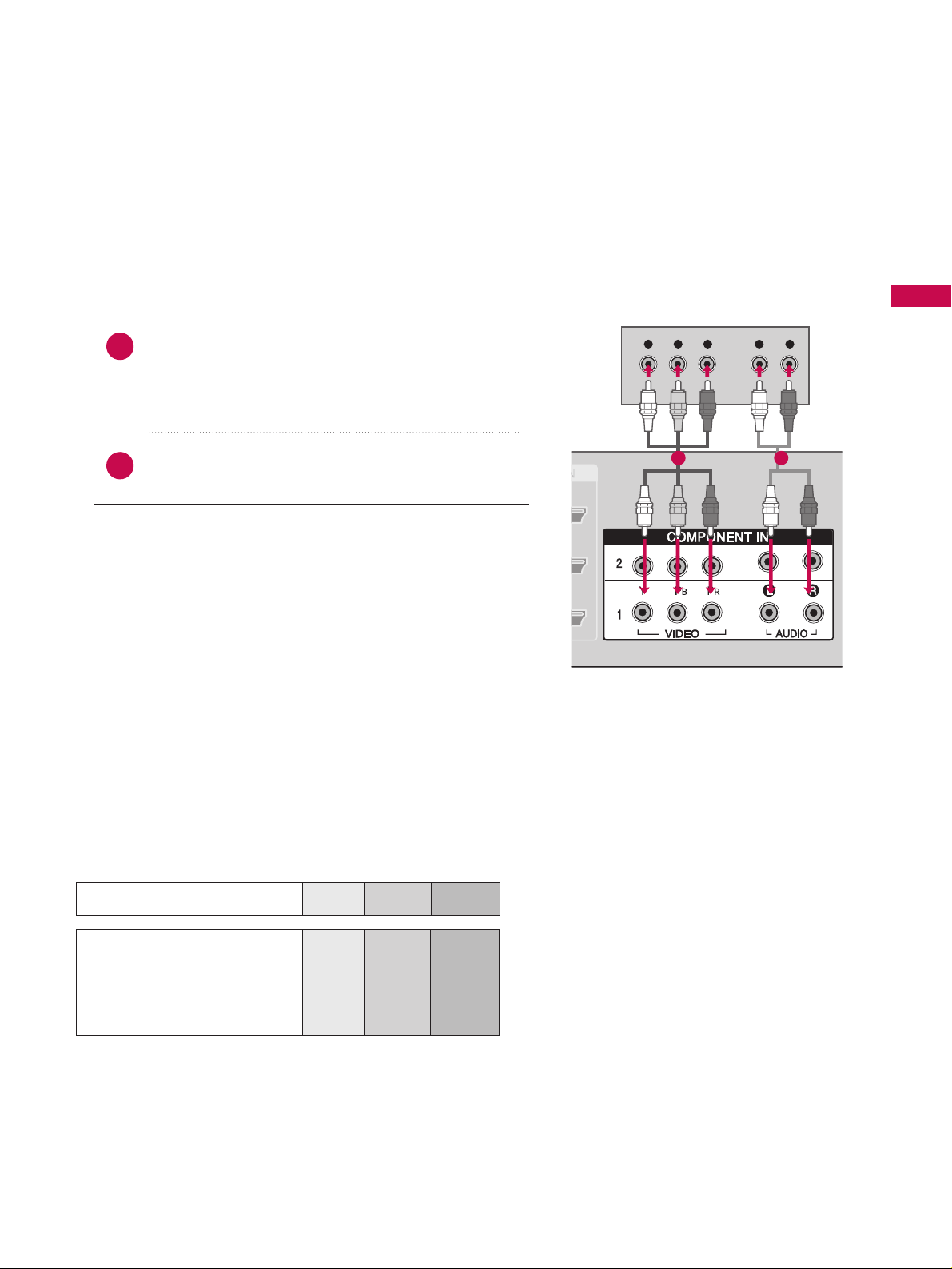
When connecting Component cable
Connect the video outputs (Y, PB
, PR
)
of the DVD to
the
CCOOMMPPOONNEE NNTT II NN VVIIDDEE OO11
jacks on the set.
Match the jack colors
(
Y = green, P
B = blue, and PR = red
)
.
Connect the audio outputs of the DVD to the
CCOOMMPPOONNEE NN TT IINN AAUU DDIIOO11
jacks on the set.
1. How to connect
2. How to use
■
Turn on the DVD player, insert a DVD.
■
Select
CCoommppoonneenntt 11
input source with using the
IINNPPUUTT
button on the remote control.
■
If connected to
CCOOMMPPOONNEENNTT IINN 22
input, select
CCoommppoonneenntt 22
input source.
■
Refer to the DVD player's manual for operating instructions.
2
1
1 2
EXTERNAL EQUIPMENT SETUP
EXTERNAL EQUIPMENT SETUP
18
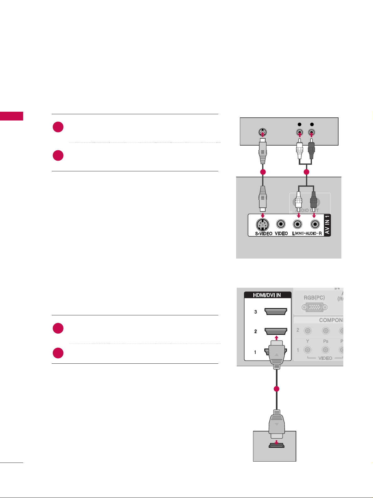
When connecting with an S-Video cable
HDMI-DVD OUTPUT
L R
S-VIDEO
AUDIO
Connect the S-VIDEO output of the DVD to the
SS--VVIIDDEEOO
input on the set.
Connect the audio outputs of the DVD to the
AAUUDDIIOO
input jacks on the set.
1. How to connect
2. How to use
■
Turn on the DVD player, insert a DVD.
■
Select
AA VV 11
input source with using the
II NNPPUUTT
button on
the remote control.
■
If connected to
AAVV II NN 22
, select
AA VV 22
input source.
■
Refer to the DVD player's manual for operating instructions.
When connecting HDMI cable
Connect the HDMI output of the DVD to the
HHDDMMII//DD VVII IINN11, 22 or33
jack on the set.
No separated audio connection is necessary.
1. How to connect
2. How to use
■
Select
HHDDMMII11,HHDDMMII22 orHHDDMMII33
input source with using
the
IINNPPUUTT
button on the remote control.
■
Refer to the DVD player's manual for operating instructions.
■
If the DVD does not support Auto HDMI, you need to set
the output resolution appropriately.
2
1
2
1
EXTERNAL EQUIPMENT SETUP
1 2
1
EXTERNAL EQUIPMENT SETUP
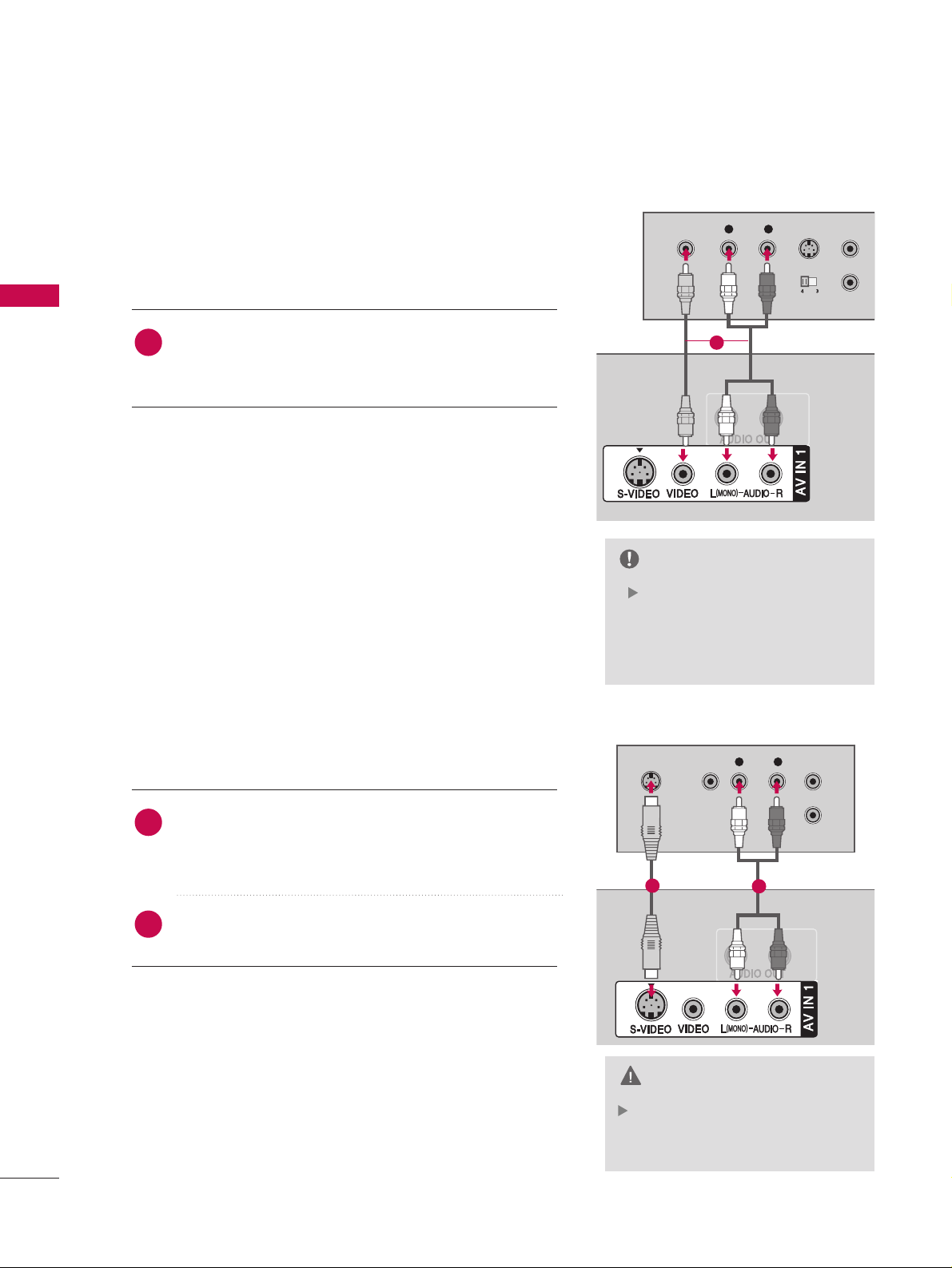
VCR SETUP
19
When connecting with an antenna
■
To avoid picture noise (interference), leave an adequate distance between the VCR and TV
■
If the 4:3 picture format is used; the fixed images on the sides of the screen may remain visible
on the screen.
L R
S-VIDEO VIDEO
OUTPUT
SWITCH
ANT IN
ANT OUT
ANTENNA/ANTENNA/
CABLE INCABLE IN
Wall Jack
Antenna
Connect the RF antenna out socket of the VCR to the
AAnntteennnnaa
socket on the set.
Connect the antenna cable to the RF antenna in socket of the VCR.
1. How to connect
■
Set VCR output switch to 3 or 4 and then tune TV to the same channel number.
■
Insert a video tape into the VCR and press PLAY on the VCR. (Refer to the VCR owner’s manual.
)
2. How to use
2
1
1
2
EXTERNAL EQUIPMENT SETUP
EXTERNAL EQUIPMENT SETUP
20
In the event that you connect
both Video and the S-Video
cables, only the S-Video will work.
CAUTION
L R
S-VIDEOVIDEO
OUTPUT
SWITCH
ANT IN
ANT OUT
ANTENNA/
CABLE IN
L R
S-VIDEO VIDEO
OUTPUT
SWITCH
ANT IN
ANT OUT
ANTENNA/
CABLE IN
Connect the
AAUUDDIIOO/VVIIDDEEOO
jacks between TV and
VCR. Match the jack colors(Video = yellow, Audio Left =
white,and Audio Right = red)
1. How to connect
2. How to use
■
Insert a video tape into the VCR and press PLAY on the
VCR. (Refer to the VCR owner’s manual.
)
■
Select
AA VV 11
input source with using the
II NNPPUUTT
button on
the remote control.
■
If connected to
AAVV II NN 22
, select
AA VV 22
input source.
If you have a mono VCR, connect the audio cable from the
VCR to the
AAUUDD II OO
LL//MMOO NN OO
jack of the set.
NOTE
When connecting with an S-Video cable
When connecting with a RCA cable
Connect the S-VIDEO output of the VCR to the
SS --
VV II DDEEOO
input on the set. The picture quality is
improved; compared to normal composite (RCA cable
)
input.
Connect the audio outputs of the VCR to the
AAUUDDIIOO
input jacks on the set.
1. How to connect
2. How to use
■
Insert a video tape into the VCR and press PLAY on the VCR.
(
Refer to the VCR owner’s manual.
)
■
Select
AAVV11
input source with using the
IINNPPUUTT
button on the
remote control.
■
If connected to
AAVV IINN 22
, select
AAVV22
input source.
1
2
1
1
1
2
EXTERNAL EQUIPMENT SETUP
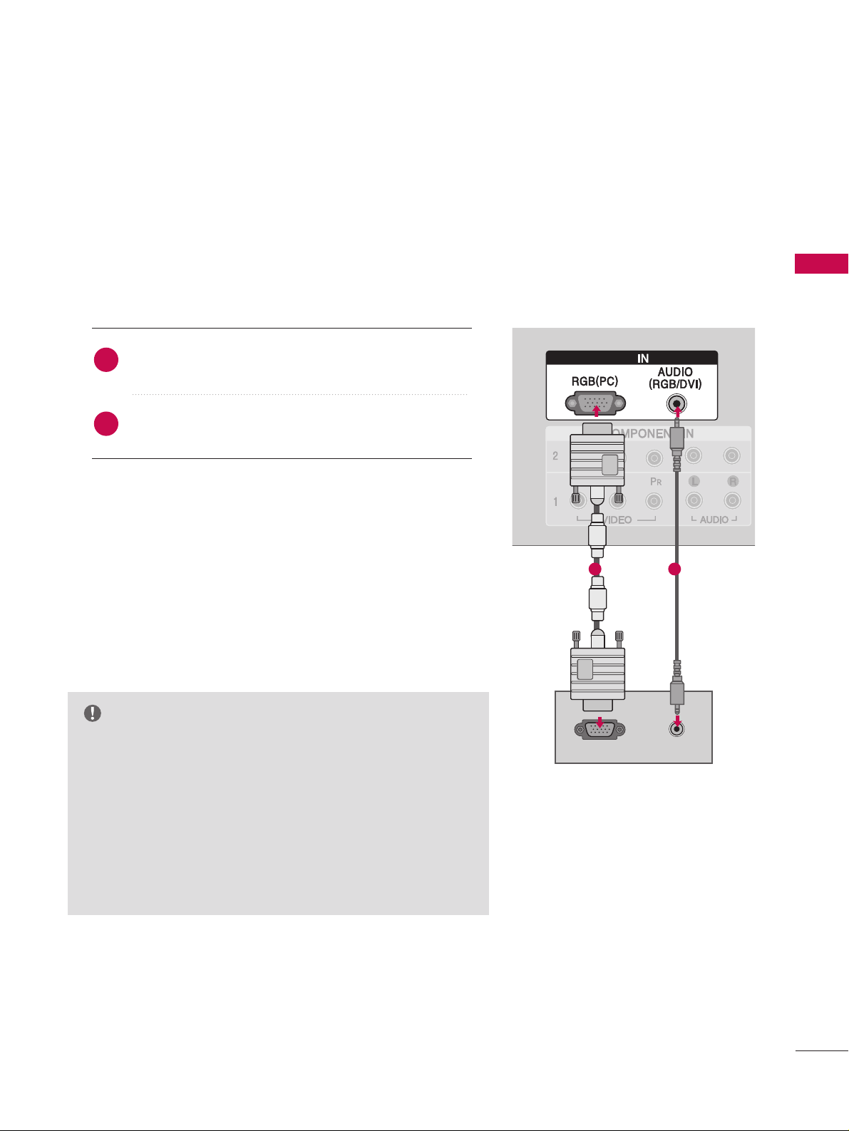
PC SETUP
21
This TV provides Plug and Play capability, meaning that the PC adjusts automatically to the TV's settings.
GG
Check the image on your TV. There may be noise associated
with the resolution, vertical pattern, contrast or brightness in
PC mode. If noise is present, change the PC output to another
resolution, change the refresh rate to another rate or adjust
the brightness and contrast on the VIDEO menu until the
picture is clear. If the refresh rate of the PC graphic card can
not be changed, change the PC graphic card or consult the
manufacturer of the PC graphic card.
NOTE
RGBRGB
RGB OUTPUT
AUDIO
RGB
When connecting D-sub 15 pin cable
Connect the RGB output of the PC to the
RRGGBB
((
PPCC
))
jack on the set.
Connect the PC audio output to the
AAUUDDIIOO
((
RRGGBB//DDVVII
))
jack on the set.
1. How to connect
2. How to use
■
Turn on the PC and the set.
■
Select
RRGGBB--PPCC
input source with using the
IINNPPUUTT
button
on the remote control.
2
1
1 2
22
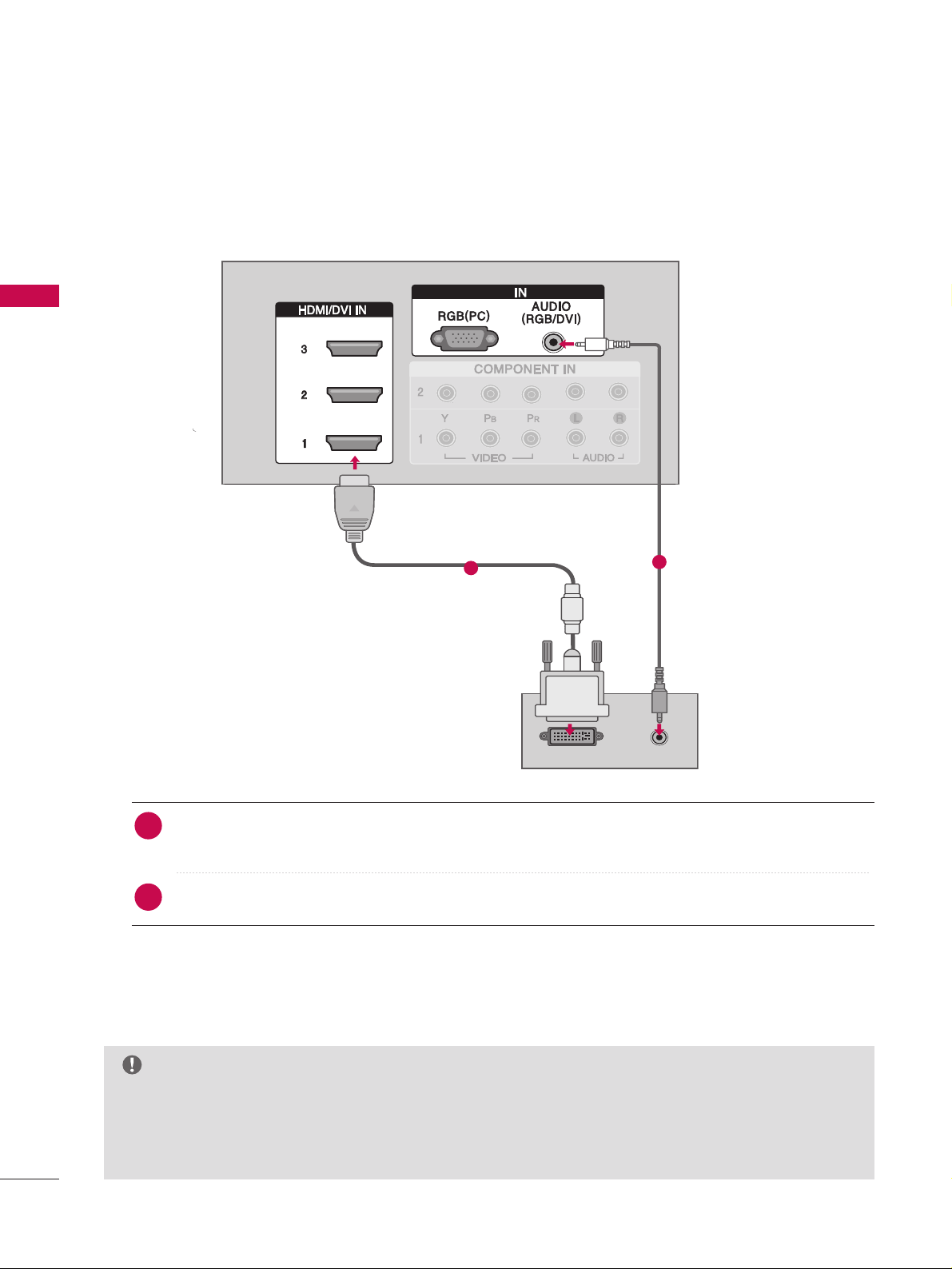
EXTERNAL EQUIPMENT SETUP
EXTERNAL EQUIPMENT SETUP
GG
If the PC has a DVI output and no HDMI output, a separated audio connection is necessary.
GG
If the PC does not support Auto DVI, you need to set the output resolution appropriately. To get the
best picture quality, adjust the output resolution of PC graphics card's output resolution to 1920x1080,
60Hz.
NOTE
DVI-PC OUTPUT
AUDIO
RGBRGB
Connect the DVI output of the PC to the
HHDDMMII//DDVVII IINN11, 22
or
33
jack on the set.
(Use the HDMI to DVI cable)
Connect the PC audio output to the
AAUUDDIIOO((RRGGBB//DDVVII
))
jack on the set.
1. How to connect
■
Turn on the PC and the set
■
Select
HHDDMMII11,HHDDMMII22 orHHDDMMII33
input source with using the
IINNPPUUTT
button on the remote control.
2. How to use
2
1
1
2
When connecting HDMI to DVI cable
EXTERNAL EQUIPMENT SETUP
23
GG
Depending on the graphics card, DOS mode may
not work if a HDMI to DVI Cable is in use.
GG
Check the image on your TV. There may be noise
associated with the resolution, vertical pattern,
contrast or brightness in PC mode. If noise is
present, change the PC output to another resolution, change the refresh rate to another rate or
adjust the brightness and contrast on the PICTURE menu until the picture is clear. If the refresh
rate of the PC graphic card can not be changed,
change the PC graphic card or consult the manufacturer of the PC graphic card.
GG
Avoid keeping a fixed image on the screen for a
long period of time. The fixed image may become
permanently imprinted on the screen.
GG
The synchronization input form for Horizontal and
Vertical frequencies is separate.
NOTES
Supported Display Specifications (RGB/HDMI-PC
)
Horizontal Vertical
Frequency(KHz)Frequency(Hz
)
31.468 70.09
31.469 70.08
31.469 59.94
37.861 72.80
37. 500 75.00
35.156 56.25
37.879 60.31
48.077 72.18
46 .875 75 .0 0
48.363 60.00
56.476 70.06
60.023 75.02
47. 776 59. 870
60.289 74.893
47.712 60.015
63.981 60.020
79.976 75.025
75.00 60.00
67.50 60.00
Resolution
720x400
1360x768
640x350
* RGB-PC mode only: 1280x768(H-60.289, V-74.893)
640x480
800x600
1024x768
1280x1024
1600x1200
1920x1080
1280x768
1280x768
EXTERNAL EQUIPMENT SETUP
EXTERNAL EQUIPMENT SETUP
24
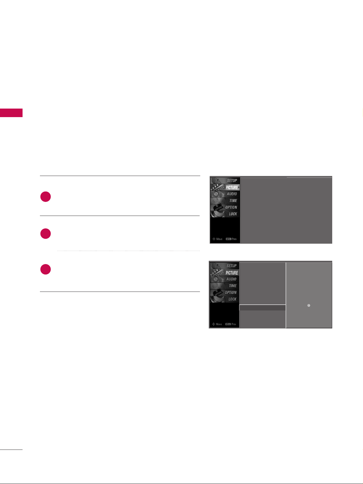
Screen Setup for PC mode
Overview
When the RGB input, of the set is connected to a PC Output, Select
RGB-PC with using the
IINNPPUUTT
button on the remote control.
When you change the resolution, select the proper resolution in
present input to see the best picture appearance.
Picture Mode
Color Temperature
XD
Advanced
Aspect Ratio
Picture Reset
Screen
G
TruM Demo
Selection ( Gor ) leads you to
thescreen adjustment menu.
Picture Mode : User1
Color Temperature : Cool
XD
Advanced
Aspect Ratio : 16:9
Picture Reset
Screen
TruM Demo
Press the
MMEENNUU
button and then useDDor EEbutton
to select the
PPIICCTTUURREE
menu.
Press the
GG
button and then useDDor EEbutton to
select
SSccrreeeenn
.
Press the
GG
button to enter the screen adjustment
menu.
2
3
1
25
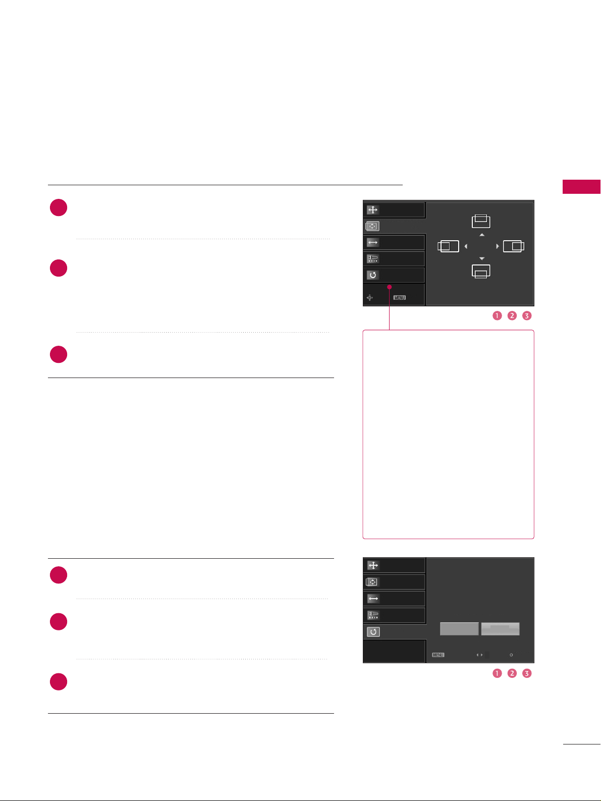
EXTERNAL EQUIPMENT SETUP
Resolution
Position
GG
Size
Phase
Reset
Move Prev
Resolution
Position
Size
Phase
Reset
GG
Initialize Settings.
Yes
No
Prev
Select
OK
RReessoolluuttiioonn
XGA (1024, 1280, 1360) isn’t
distinguished because of having
the same H/V Sync Time.
This function is you to select the
Default Sync Time.
PPoossiittiioonn
This function is to adjust picture
to left/right and up/down as you
prefer.
SSiizzee
This function is to minimize any
vertical bars or stripes visible on
the screen background. And the
horizontal screen size will also
change.
PPhhaassee
This function allows you to
remove any horizontal noise and
clear or sharpen the image of characters.
Use DDor EEbutton to select
RReessoolluuttiioonn, PPoossiittiioonn, SSiizzee
,
or
PPhhaassee
.
Press the
EENNTTEERR
button and then use
DD / EE
or
FF / GG
button to make appropriate adjustments.
■
The
PPhhaassee
adjustment range is
--1166~++1166
.
■
The
SSiizzee
adjustment range is
--3300~++3300
.
Press the
EENNTTEERR
button.
Adjustment for screen Resolution, Position, Size, Phase, Reset
Use DDor EEbutton to select
RReesseett
.
Press the
EENNTTEERR
button and then use
FF
or GGbutton to
select
YYeess
.
Press the
EENNTTEERR
button.
Initializing (Reset to original factory values
)
2
3
1
2
3
1
To initialize the adjusted values.
EXTERNAL EQUIPMENT SETUP
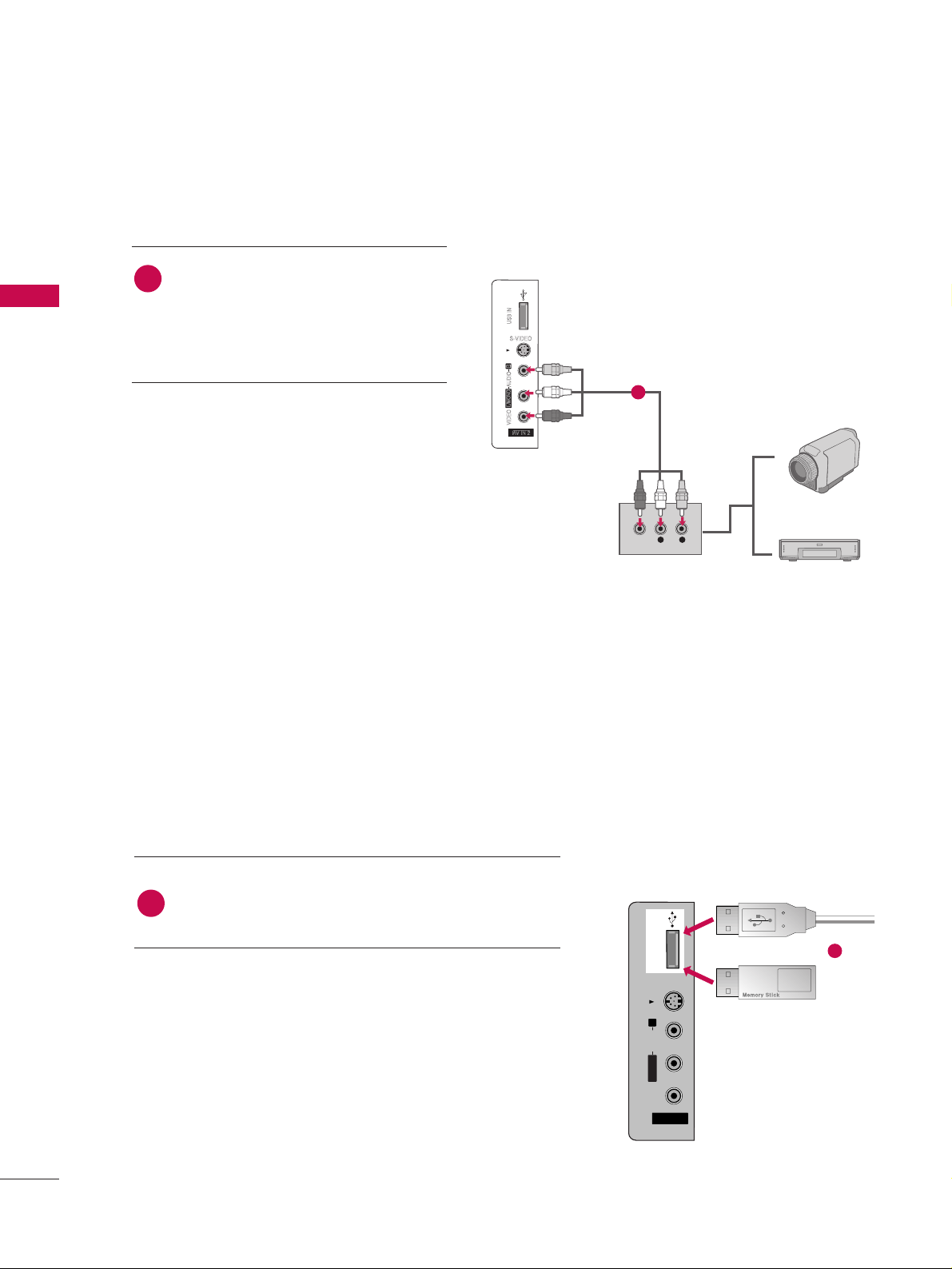
OTHER A/V SOURCE SETUP
EXTERNAL EQUIPMENT SETUP
26
Camcorder
Video Game Set
Connect the
AAUUDDIIOO/VVIIDDEEOO
jacks
between TV and external equipment.
Match the jack colors
.
(
Video = yellow, Audio Left = white, and
Audio Right = red
)
1. How to connect
2. How to use
■
Select
AAVV22
input source with using the
IINNPPUUTT
button on the remote control.
■
If connected to
AAVV IINN 11
input, select
AAVV11
input source.
■
Operate the corresponding external equipment.
1
S-VIDEO
L R
VIDEO
1
The TV has a special signal output capability which allows you to hook up the second TV or monitor.
AV IN 2V IN 2
L/L/MONOMONO
R
AUDIOAUDIO
VIDEOVIDEO
S-VIDEO
USB INUSB IN
Connect the USB device to the
UUSS BB IINN
jacks on the
side of TV.
1. How to connect
1
2. How to use
■
After connecting the
UUSS BB IINN
jacks, you use the
function. (
GG
pp..3399
)
MEDIAMEDIA
HOST HOST
1
or
USB IN SETUP
EXTERNAL EQUIPMENT SETUP
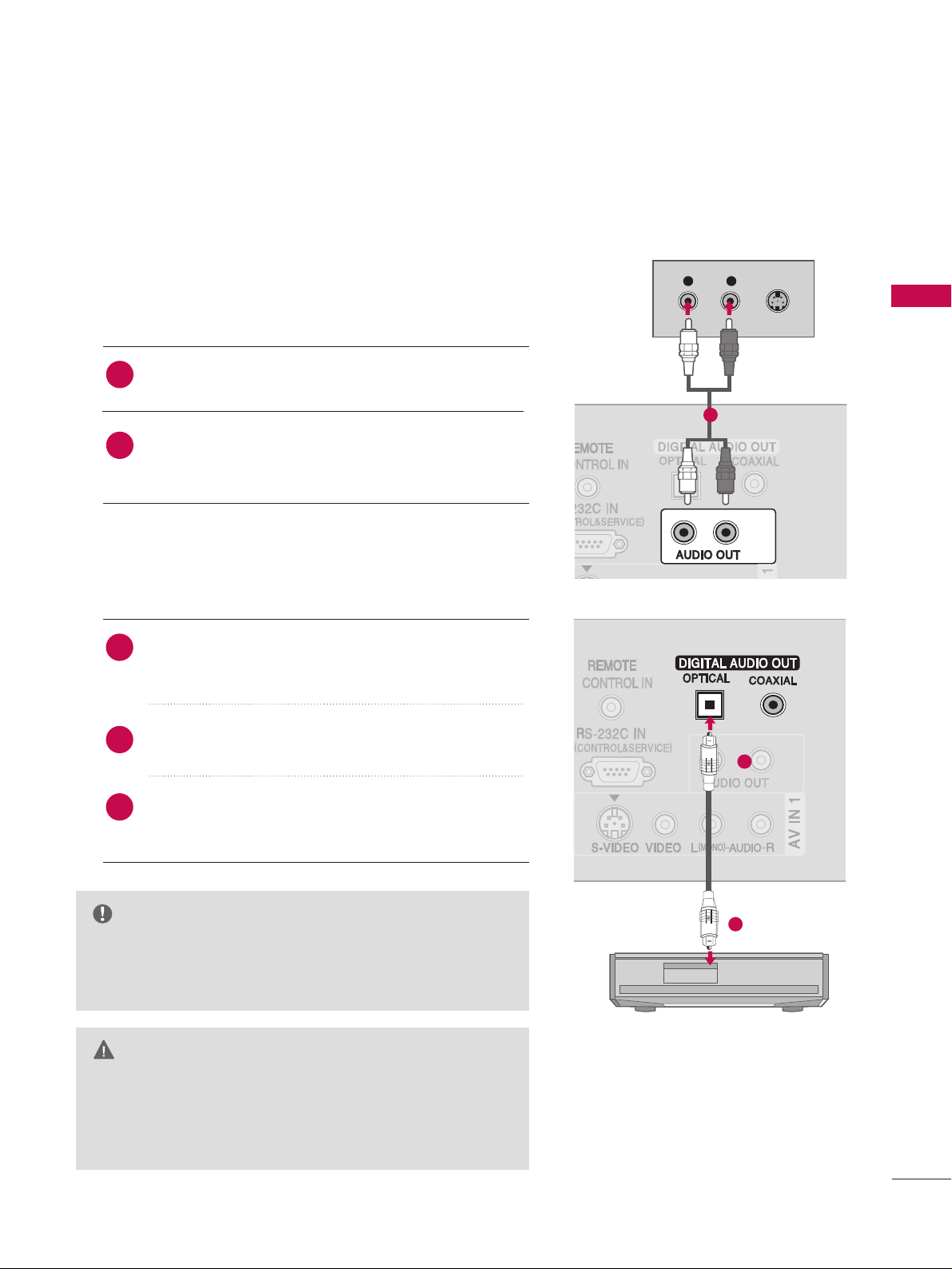
AUDIO OUT SETUP
27
Send the TV’s audio to external audio equipment via the Audio Output port.
GG
When connecting with external audio equipment, such as
amplifers or speakers, please turn the TV speakers off.
(
GG
pp..6622
)
NOTE
GG
Do not look into the optical output port. Looking at the
laser beam may damage your vision.
GG
Block the SPDIF out(optical/coaxial) about the contents
with ACP(Audio Copy Protection) function.
CAUTION
Connect one end of the optical or coaxial cable to the
TV’s
OOPP TTIICCAALL
or
CCOOAAXXIIAALL
port of
DDIIGGIITTAALL AAUUDDIIOO
OOUUTT
.
Connect the other end of the optical or coaxial cable
to the digital audio input on the audio equipment.
Set the “TV Speaker option - Off ” in the AUDIO menu.
(
GG
pp..6622
). See the external audio equipment instruction
manual for operation.
1. How to connect
2
3
1
1
2
L R
S-VIDEO
Analog
Digital
Connect audio outputs to the TV’s
AAUUDDIIOO OOUUTT
jacks.
Set the “TV Speaker option - Off ” in the AUDIO menu.
(
GG
pp..6622
). See the external audio equipment instruction
manual for operation.
2
1
1
WATCHING TV / CHANNEL CONTROL
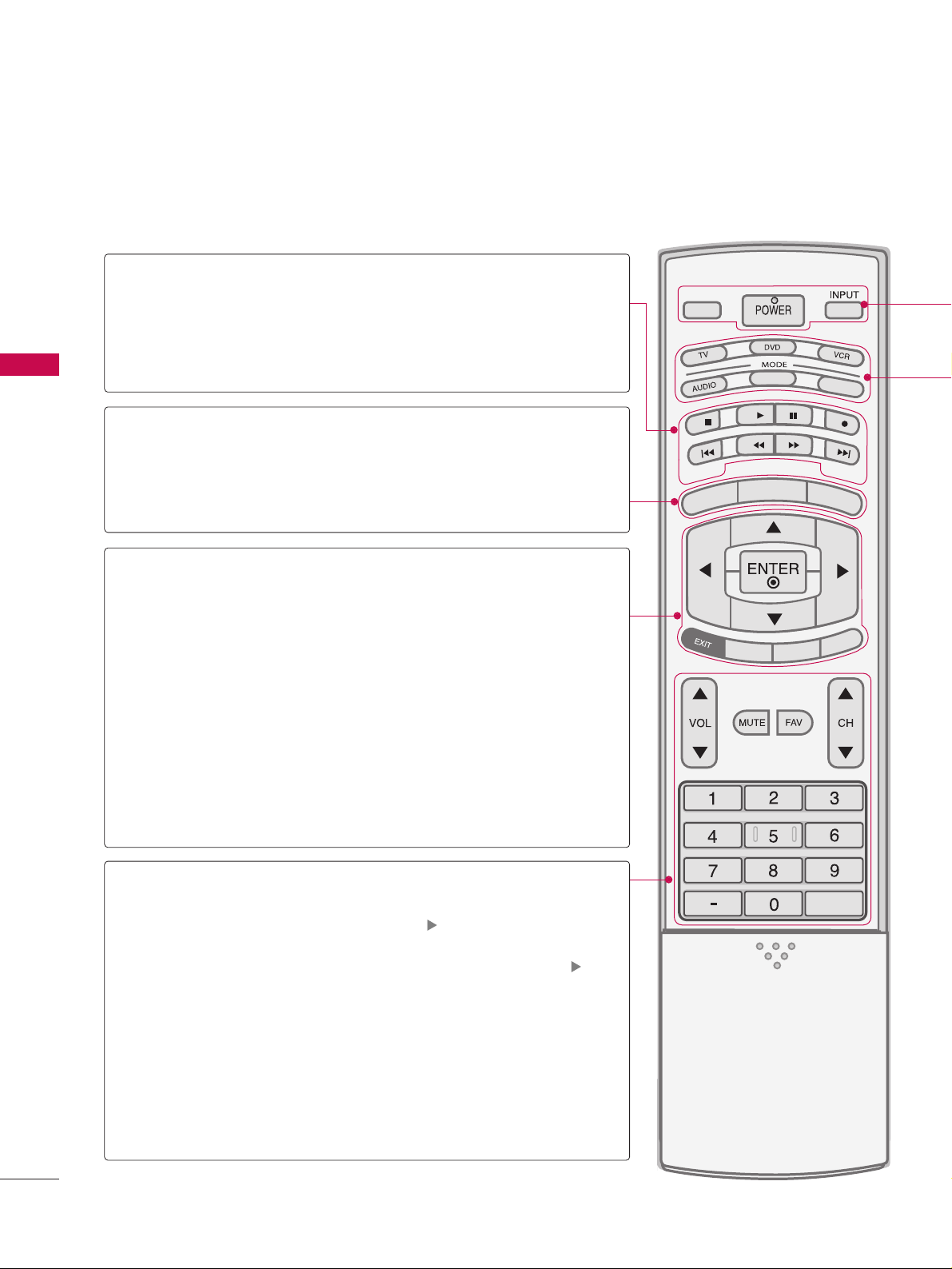
REMOTE CONTROL FUNCTIONS
WATCHING TV /CHANNEL CONTROL
28
APM
CC
AUTO DEMO
M/C EJECT
TV INPUTTV INPUT
STBSTB
MENU
BRIGHT +
B
RIGHT -
TIMER
RATIO
SIMP
LINK
BACKBACK
TV INPUT
STB
BACK
TV INPUT
STB
BACK
PICTURE
SOUND
SAP
CC
MARK
USB EJECT
MEDIA HOSTMEDIA HOST
MEDIA HOST
MEDIA HOST
BRIGHT +/-
THUMBSTICK
(Up/Down/Left
Right/ENTER)
EXIT
TIMER
RATIO
SIMPLINK
VOLUME UP
/DOWN
MUTE
FAV
CHANNEL
UP/DOWN
BACK
— (DASH)
■
Controls the mode.
■
Control video cassette recorders or DVD players.
Displays the main menu.
■
Adjust brightness on screen.
■
It turns to the default settings brightness by changing
mode source.
■
Navigate the on-screen menus and adjust the system
settings to your preference.
Clear all on-screen displays and return to TV viewing from
any menu.
Select the amount of time before your TV turns off automatically.
GG
pp..7722
Change the aspect ratio.
GG
pp..4466
See a list of AV devices connected to TV.
When you toggle this button, the SimpLink menu appears
at the screen.
Increase/decrease the sound level.
Switch the sound on or off.
pp..3300
Scroll through the programmed Favorite channels.
pp..3344
Select available channels.
Tune to the last channel viewed.
Used to enter a program number for multiple
program channels such as 2-1, 2-2, etc.
MEDIAMEDIA
HOST HOST
mode control
buttons
MEDIAMEDIAMEDIA
HOST HOST HOST
MEDIA
HOST
NUMBER button
VCR/DVD
buttons
MENU
When using the remote control, aim it at the remote control sensor on the TV.
 Loading...