

LG 52LB5D, 42LB5D Owner’s Manual

LCD TV
OWNER'S MANUAL
LCD TV MODELS
37LBSD / 42LBSD / 47LBSD
52LBSD
32LB4D / 37LB4D / 42LB4D
PHeaseread this manua[ carefuHHybefore operating your set.
Retain it for future reference.
Record mode[ number and senaH number of the set.
See the [abe[ attached on the back cover and quote this
information to your deaHer when you require service.
ENERGY STAR is a set of power-saving
guidelines issued by the U.S.
Environmental Protection Agency(EPA).
As an ENERGY STAR
Partner LGE U.S.A.,
Inc. has determined
that this product
meets the ENERGY
STAR guidelines for
energy efficiency,

SRS(@) *+
_ m _ HTAL
_' is a trademark of SRS Labs, Inc.
TruSurround XT technology is incorporated under
license from SRS Labs, Inc.
DIGITAL
Manufactured under license from Dolby Laboratories.
+
"Dolby"and the doub[e-D symbol are trademarks of
Dolby Laboratories.
FULLHD
1080P
_sImPLIRK
LG TV with this logo displays Full HD(high-defini-
tion) 1080p native resolution by receiving and pro-
cessing a Full HD 1080p signal.
LG TV with this logo can play MP3 music from a
MP5 player, such as iPOD, and JPEG images from a
digital camera through the USB unit.
With HDMI CEC support of LG's audio/video device
connected to the HDMI (high-definition multimedia
interface), LG TV with this logo works easily with one
remote control.
It has three HDMI ports that connect audio and
video devices with one cable and produces the high-
est quality digital images and sound.
H [n[ r+
High-definition television. High-resolution digital
te[evMon broadcast and playback system composed
of roughly a million or more pixe[s, 15:9 aspect4_tio
screens, and AC3 digital audio. A subset of digital
television, HDTV fonTlats fflc[ude 1080i and 720p
resolutions.
HDMI TM, the HDMI logo and High-Definition
Multimedia Interface are trademarks or registered
trademarks of HDMI Licensing."
LG's own special digital image generator; consisting
of a full digital image processor; six different main
picture quality factors.
WARNING/CAUTION
WARNING / CAUTION
WARNING / CAUTION
To prevent fire or shock hazards, do not expose
this product to rain or moisture.
Class B digital device
This equipment has been tested and found to com-
ply with the limits for a Class g digital device, pur-
suant to Part 15 of the FCC Rules. These limits are
designed to provide reasonable protection against
harmful interference in a residential installation. This
equipment generates, uses and can radiate radio fre-
quency energy and, if not installed and used in
accordance with the instructions, may cause harmful
interference to radio communications. However,
there is no guarantee that interference w[[[ not
occur in a particular installation, if this equipment
does cause harmful interference to radio or televi-
sion reception, which can be determined by turning
the equipment off and on, the user is encouraged to
try to correct the interference by one or more of
the following measures:
- Reorient or relocate the receiving antenna.
- increase the separation between the equipment
and receiver.
- Connect the equipment to an outlet on a circuit
different from that to which the receiver is con-
nected.
- Consult the dealer or an experienced radio/TV
technician for help.
TO REDUCE THE RISK OF FIRE AND ELEC-
TRIC SHOCK. DO NOT EXPOSE THIS PRO-
DUCT TO RAIN OR MOISTURE.
NOTE TO CABLE/TV INSTALLER
This reminder is provided to call the CATV sys-
tem installer's attention to Article 820-40 of the
National Electric Code (U.S.A.). The code pro-
vides guidelines for proper grounding and. in
particular, specifies that the cable ground shall
be connected to the grounding system of the
building, as close to the point of the cable entry
as praei_caL
Any changes or modifications not express[.]/
approved by the party responsible for compliance
could void the user's authority to operate the
equipment,
Do not attempt to modify this product in any way
without written authorization from LG Electronics.
Unauthorized modification could void the user's
authority to operate this product
SAFETY INSTRUCTIONS
IMPORTANT SAFETYINSTRUCTIONS
Important safety instructions shall be provided with each apparatus. This information shall be given in a se-
parate booklet or sheet, or be located before any operating instructions in an instruction for installation for
use and supplied with the apparatus.
This information shall be given in a language acceptable to the country where the apparatus is intended to
be used.
The important safety instructions shall be entitled "Important Safety Instructions': The following safety
instructions shall be included where applicable, and, when used, shall be verbatim as follows. Additional safe-
ty information may be included by adding statements after the end of the following safety instruction list. At
the manufacturer's option, a picture or drawing that illustrates the intent of a specific safety instruction may
be placed immediately adjacent to that safety instruction :
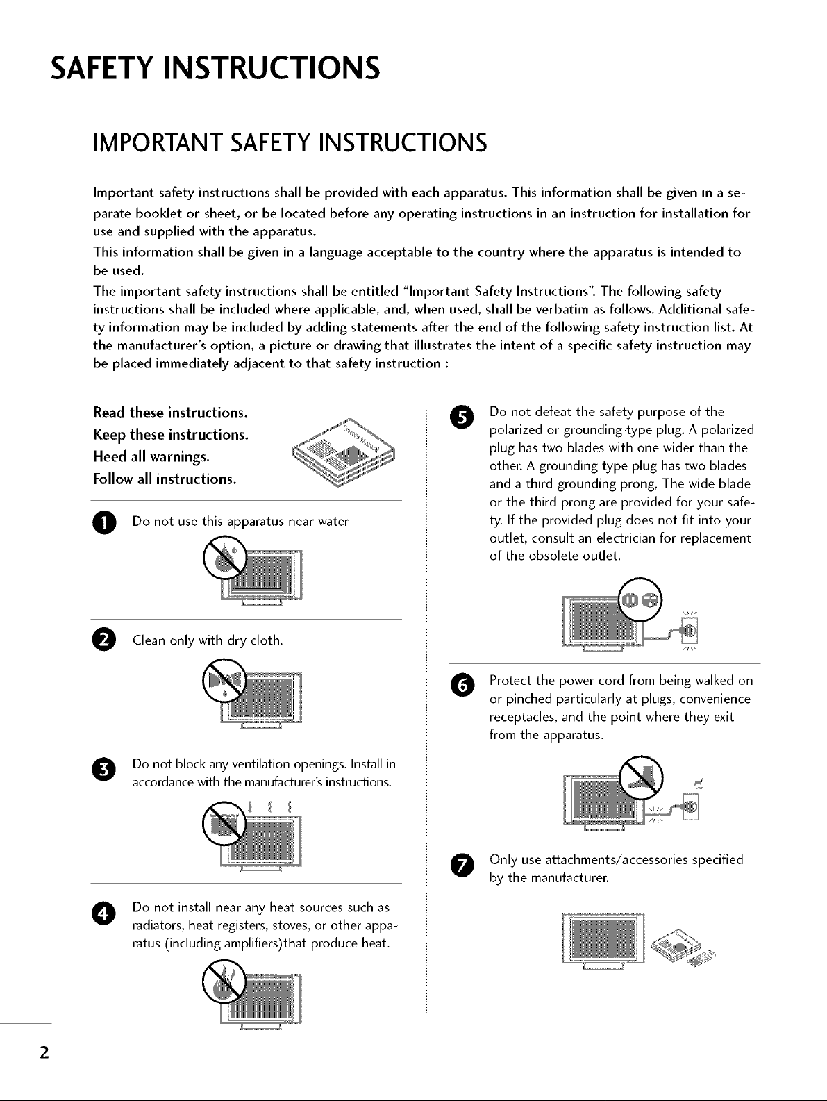
Read these instructions.
Keep these instructions.
Heed all warnings.
Follow all instructions.
O Do not use this apparatus near water
Clean only with dry cloth.
Do not block any ventilation openings. Install in
accordancewith the manufacturer'sinstructions.
Do not defeat the safety purpose of the
0
polarized or grounding-type plug. A polarized
plug has two blades with one wider than the
other. A grounding type plug has two blades
and a third grounding prong, The wide blade
or the third prong are provided for your safe-
ty. If the provided plug does not fit into your
outlet, consult an electrician for replacement
of the obsolete outlet.
Protect the power cord from being walked on
O
or pinched particularly at plugs, convenience
receptacles, and the point where they exit
from the apparatus.
Only use attachments/accessories specified
by the manufacturer.
Do not install near any heat sources such as
radiators, heat registers, stoves, or other appa-
ratus (including amplifiers)that produce heat.
2
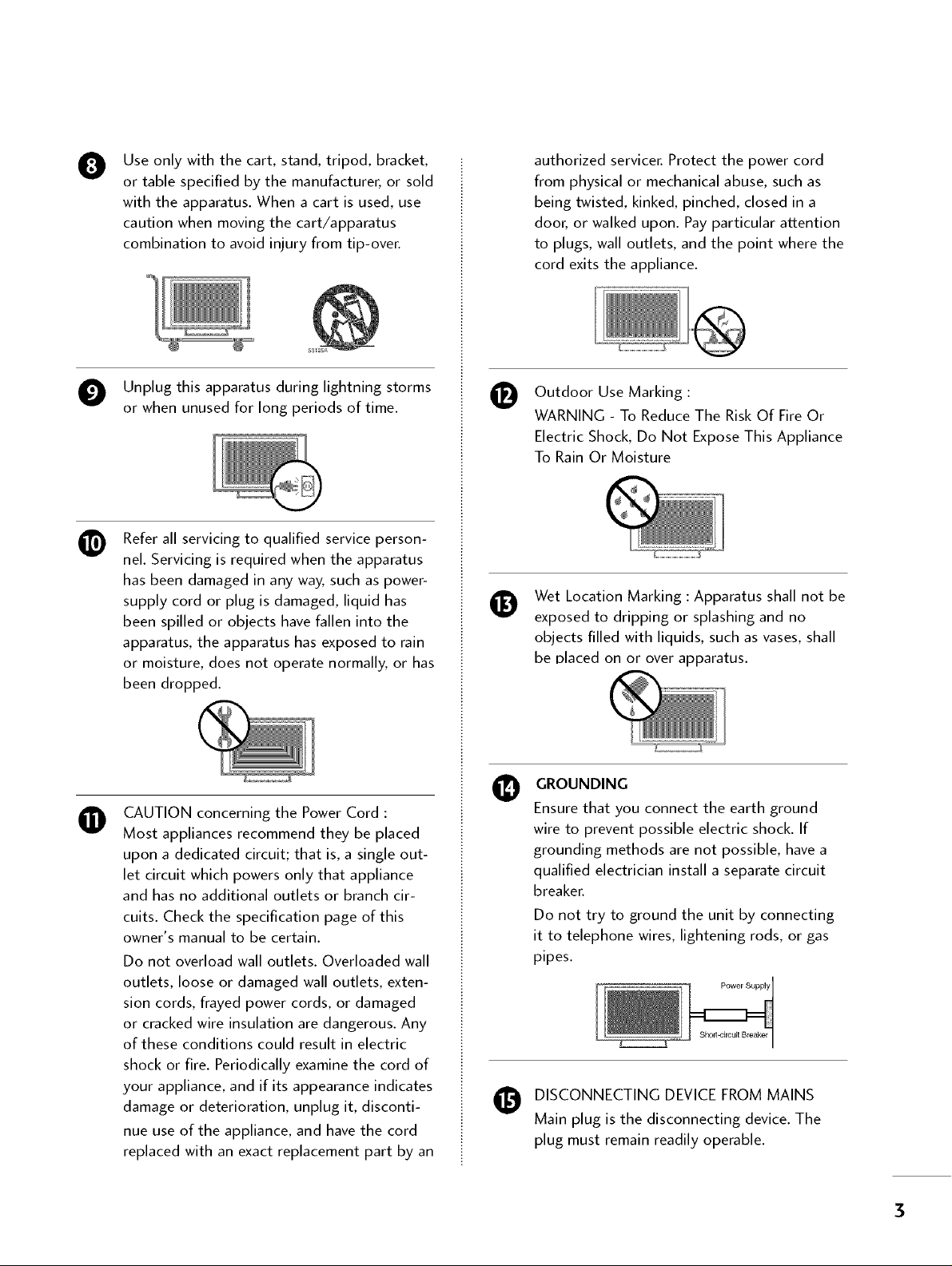
Use only with the cart, stand, tripod, bracket,
0
or table specified by the manufacturer, or sold
with the apparatus. When a cart is used, use
caution when moving the cart/apparatus
combination to avoid injury from tip-over.
authorized servicer. Protect the power cord
from physical or mechanical abuse, such as
being twisted, kinked, pinched, closed in a
door, or walked upon. Pay particular attention
to plugs, wall outlets, and the point where the
cord exits the appliance.
O Unplug this apparatus during lightning storms
or when unused for long periods of time.
Refer all servicing to qualified service person-
nel. Servicing is required when the apparatus
has been damaged in any way, such as power-
supply cord or plug is damaged, liquid has
been spilled or objects have fallen into the
apparatus, the apparatus has exposed to rain
or moisture, does not operate normally, or has
been dropped.
CAUTION concerning the Power Cord :
O
Most appliances recommend they be placed
upon a dedicated circuit; that is, a single out-
let circuit which powers only that appliance
and has no additional outlets or branch cir-
cuits. Check the specification page of this
owner's manual to be certain.
Do not overload wall outlets. Overloaded wall
outlets, loose or damaged wall outlets, exten-
sion cords, frayed power cords, or damaged
or cracked wire insulation are dangerous. Any
of these conditions could result in electric
shock or fire. Periodically examine the cord of
your appliance, and if its appearance indicates
damage or deterioration, unplug it, disconti-
nue use of the appliance, and have the cord
replaced with an exact replacement part by an
Outdoor Use Marking :
WARNING - To Reduce The Risk Of Fire Or
Electric Shock, Do Not Expose This Appliance
To Rain Or Moisture
Wet Location Marking : Apparatus shall not be
exposed to dripping or splashing and no
objects filled with liquids, such as vases, shall
be Dlaced on or over apparatus.
GROUNDING
Ensure that you connect the earth ground
wire to prevent possible electric shock. If
grounding methods are not possible, have a
qualified electrician install a separate circuit
breaker.
Do not try to ground the unit by connecting
it to telephone wires, lightening rods, or gas
pipes.
Power Supply
DISCONNECTING DEVICE FROM MAINS
Main plug is the disconnecting device. The
plug must remain readily operable.
3
CONTENTS
WARNING / CAUTION ........................... 1
SAFETY INSTRUCTIONS ..........................2
FEATURES OF THIS TV ................ 6
PREPARATION
Accessories .............................. 7
Front Panel Controls ...................... 8
Back Panel Information ................... 10
Attaching the TV to a Wall ................. 12
Stand Installation ........................ 13
Back Cover for Wire Arrangement ........... 14
Desktop Pedestal Installation ............... 16
Vesa Wall Mounting ....................... 16
Antenna or Cable Connection .............. 17
EXTERNAL EQUIPMENT SETUP
HD Receiver Setup .......................................... 18
DVD Setup ...................................................... 21
VCR Setup ...................................................... 23
Other A/V Source Setup ................................. 25
PCSetup ........................................................ 26
USB In Setup .................................................. 32
Audio Out Setup ............................................. 33
WATCHING TV / CHANNEL CONTROL
Remote Control Functions .................. 54
Turning on TV ........................... 36
Channel Selection ....................... 37
VolumeAdjustment ...................... 38
On-Screen Menus Selection ................ 59
Channel Setup
- Auto Scan ( Auto Tuning) .............. 40
- Add / Delete Channel ( Manual Tuning) .. 41
- Channel Editing ....................... 42
Input List ............................... 43
SimpLink ............................... 44
Input Label ............................. 46
MEDIAHOST
Entry Modes ............................ 47
Photo List .............................. 48
Music List .............................. 52
PICTURE CONTROL
Picture Size (Aspect Ratio) Control .......... 54
Preset Picture Settings
- Picture Mode - Preset ................ 55
- Color Tone - Preset ................... 56
ManualPictureAdjustment
- Picture Mode - User Mode ............ 57
- Color Tone - User Mode ............... 58
XD - PictureImprovementTechnology........... 59
Advanced - Cinema 3:2 Pulldown Mode ...... 60
Advanced - Black(Darkness) Level .......... 61
Advanced - TruM ......................... 62
Picture Reset ............................ 63
....
SOUND & LANGUAGE CONTROL
Auto Volume Leveler ( Auto Volume) ......... 64
Preset Sound Settings( Sound Mode) ........ 65
Sound Setting Adjustment - User Mode ........ 66
Balance ................................. 68
Stereo / SAP Broadcast Setup .............. 69
TV Speakers On/Off Setup ................ 70
Audio Language ......................... 71
On-Screen Menus Language Selection ....... 72
Caption Mode
- Analog BroadcastingSystemCaptions .... 73
- Digital Broadcasting System Captions ...75
- Caption Option ..................... 76
4
TIME SETTING
Clock Setting
- Auto Clock Setup ................... 77
- Manual Clock Setup .................. 78
Auto On/Off Time Setting ................. 79
Sleep Time Setting ........................ 80
Auto Shut-off Setting ..................... 81
Z_ ¸ _ 7 =7_Z _ 7_ =_ _ _:_ _...... _ _
PARENTAL CONTROL/RATINGS
Set Password& Lock System ............... 82
Channel Blocking ........................ 84
Movie & TV Rating ....................... 85
External Input Blocking .................... 88
Key Lock ............................... 88
APPEND IX
Troubleshooting .......................... 89
Maintenance ............................ 91
Product Specifications .................... 92
Programming the Remote Control .......... 94
IR Codes ............................... 98
External Control through RS-232C ......... 100
5
FEATURESOF THIS TV
160 ° - Wide angle range of vision
Your flat panel plasma screen offers an exceptionally
broad viewing angle of over 160 degrees. This means
that the display is clear and visible to viewers any-
where in the room.
Wide Screen
The wide screen offers a theater-like experience in
your own home.
Multimedia
Connect your plasma display to a PC and use it for
conferencing, games, and Internet browsing. The
Picture-in-Picture feature allows you to view your PC
and video images simultaneously.
Versatile
The light weight and thin size makes it easy to install
your TV display in a variety of locations where con-
ventional TVs do not fit.
The TV Manufacturing Process: a few minute
colored dots may be present on the TV
screen
The TV is composed of 0.9 to 2.2 million cells. A
few cell defects will normally occur in the TV manu-
facturing process. Several tiny, minute colored dots
visible on the screen should be acceptable. This also
occurs in other Plasma TV manufacturers' products.
The tiny dots appearing does not mean that this TV
is defective. Thus a few cell defects are not sufficient
cause for the TV to be exchanged or returned. Our
production technology minimizes these cell defects
during the manufacture and operation of this prod-
uct.
On Disposal
a. The fluorescent lamp used in this product con-
ta[ns a small amount of mercury,
b, Do not dispose of this product wffh genera[
household waste,
c, Disposal of this product must be carried out in
accordance to the regulations of your local
authorffy,
_ If the TV feels cold to the touch, there may be a
small "flicker" when it is turned on. This is normal,
there is nothing wrong with TV.
Some minute dot defects may be visible on the
screen, appearing as tiny red, green, or blue spots.
However, they have no adverse effect on the moni-
tor's performance.
Avoid touching the LCD screen or holding your fin-
ger(s) against it for long periods of time. Doing so
may produce some temporary distortion effects on
the screen.
6
PREPARATION
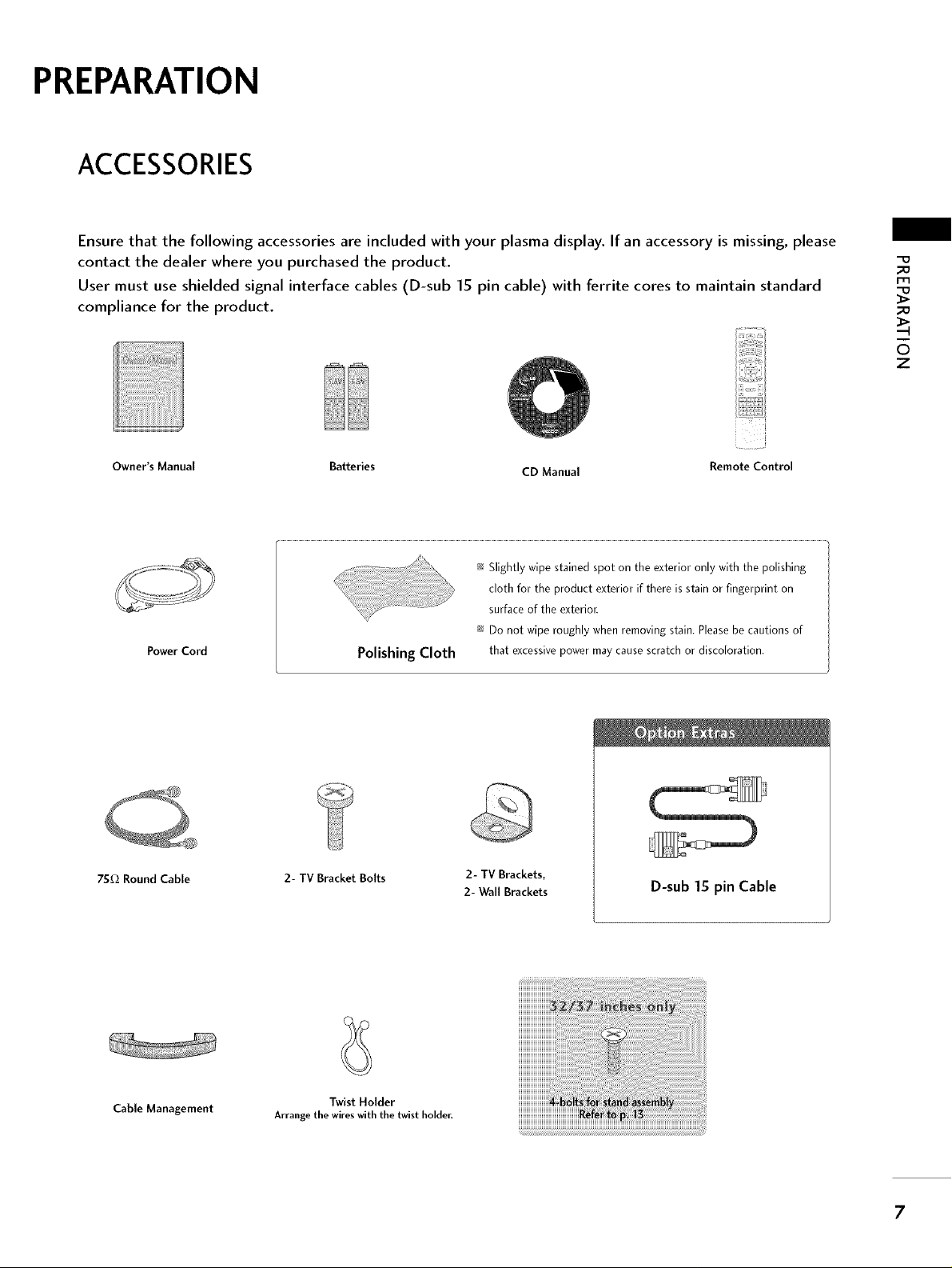
ACCESSORIES
Ensure that the following accessories are included with your plasma display. If an accessory is missing, please
contact the dealer where you purchased the product.
User must use shielded signal interface cables (D-sub 15 pin cable) with ferrite cores to maintain standard
compliance for the product.
Owner's Manual Batteries CD Manual Remote Control
_0
FIq
_o
6
z
Power Cord
75f_ Round Cable 2- TV Bracket Bolts
Polishing Cloth
_ Slightly wipe stained spot on the exterior only with the polishing
cloth for the product exterior if there is stain or fingerprint on
surface of the exterior.
_ Do not wipe roughly when removing stain. Please be cautions of
that excessive power may cause scratch or discoloration.
2- TV Brackets,
2- Wall Brackets
D-sub 15 pin Cable
Cable Management
Arrange the wires with the twist holder.
Twist Holder
7
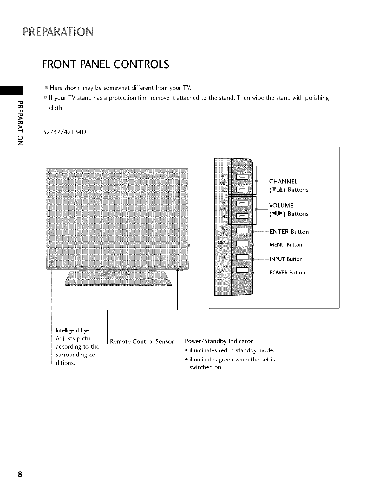
FRONT PANELCONTROLS
_ Here shown may be somewhat different from your TV.
_ If your TV stand has a protection film, remove it attached to the stand. Then wipe the stand with polishing
_o
m
_o
z
cloth.
32/37/42LB4D
(T,A) Buttons
VOLUME
(_II,I_) Buttons
ENTER Button
Button
Intelligent Eye
Adjusts picture
according to the
surrounding con-
ditions.
Remote Control Sensor
Button
Power/Standby Indicator
• illuminates red in standby mode.
• illuminates green when the set is
switched on.
8
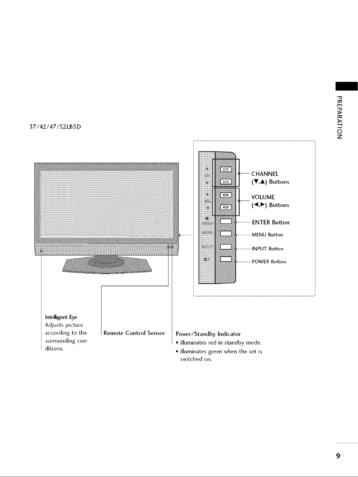
37/42/47/52LB5D
_D
_D
z
(V,A) Buttons
VOLUME
(_II,I_) Buttons
ENTER Button
MENU Button
INPUT Button
POWER Button
Intelligent Eye
Adjusts picture
according to the
surrounding con-
ditions.
Remote Control Sensor
Power/Standby Indicator
• illuminates red in standby mode.
• illuminates green when the set is
switched on.
9
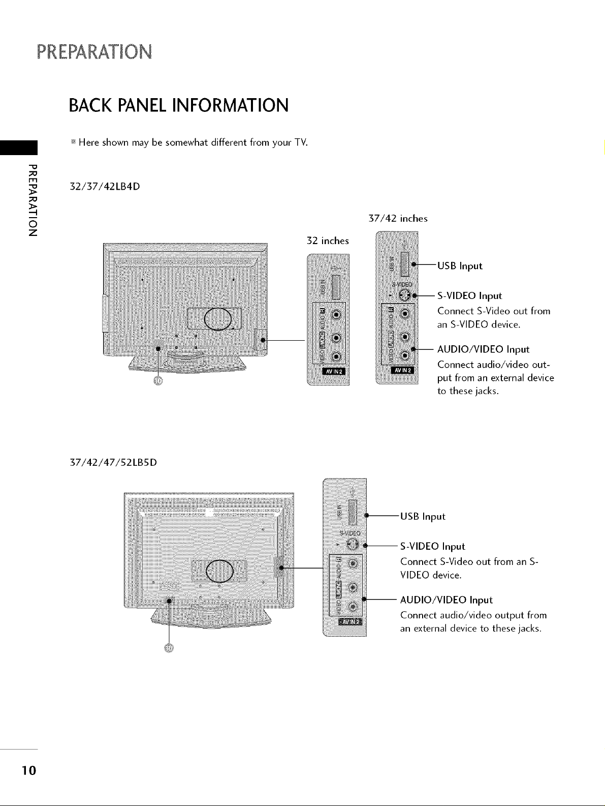
BACK PANELINFORMATION
_ Here shown may be somewhat different from your TV.
_o
32/37/42LB4D
_o
37/42 inches
z
32 inches
Input
Input
Connect S-Video out from
an S-VIDEO device.
AUDIO/VIDEO Input
Connect audio/video out-
put from an external device
to these jacks.
37/42/47/52LB5D
!i!!!!!iiiiii!ilili
S-VIDEO Input
Connect S-Video out from an S-
VIDEO device.
AUDIO/VIDEO Input
................. Connect audio/video output from
__ an external device to these jacks.
10
_o
I-r't
_o
®
RGB(PC) (RGB/DVI)
VIDEO AUDIO
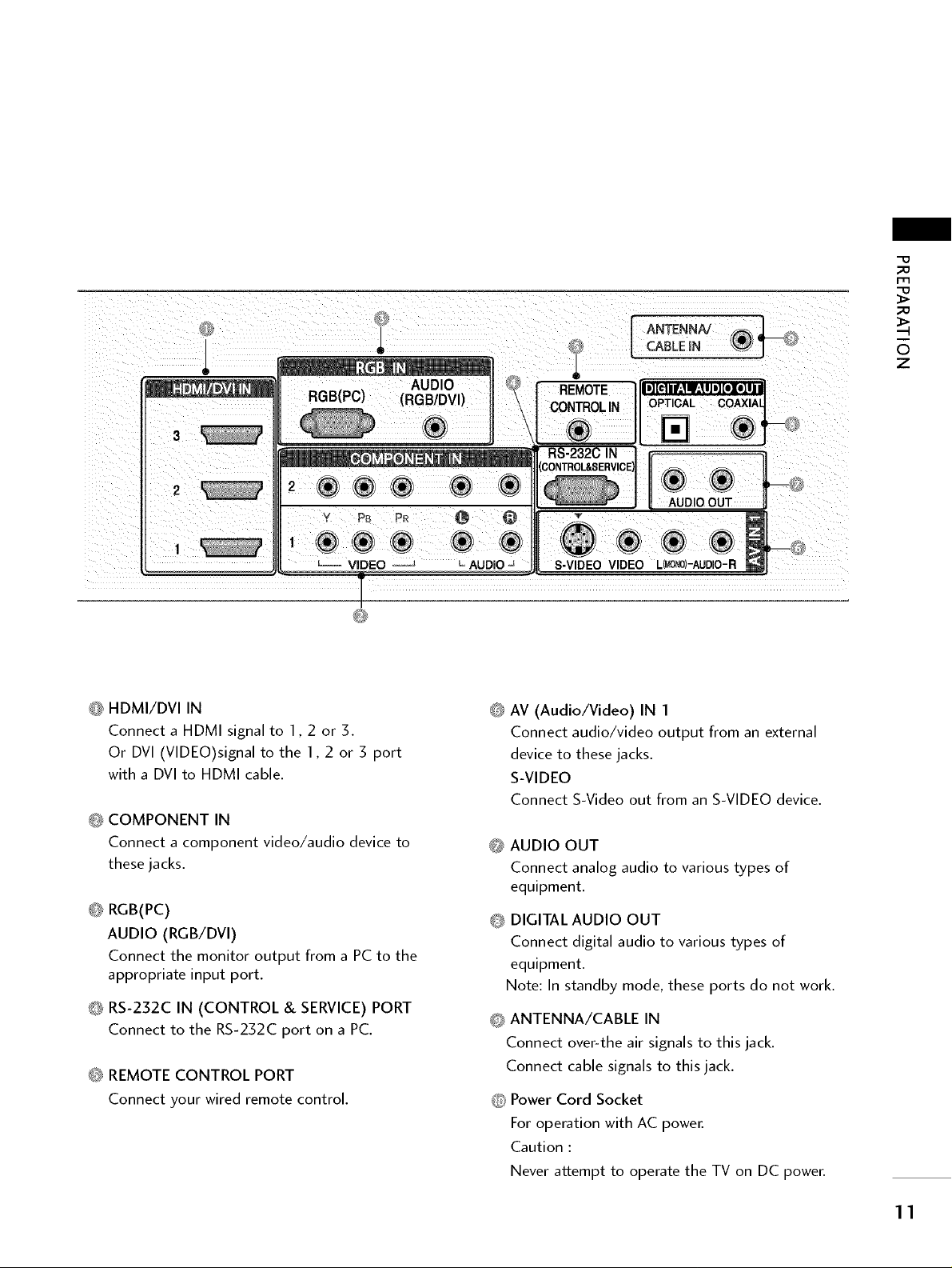
O HDMI/DVI IN
Connect a HDMI signal to 1,2 or 3.
Or DVI (VIDEO)signal to the 1,2 or 3 port
with a DVI to HDMI cable.
O COMPONENT IN
Connect a component video/audio device to
these jacks.
<b RGB(PC)
AUDIO (RGB/DVI)
Connect the monitor output from a PC to the
appropriate input port.
O RS-232C IN (CONTROL & SERVICE) PORT
Connect to the RS-232C port on a PC.
O REMOTE CONTROL PORT
Connect your wired remote control.
AUDIO
CABLEIN
OPTICAL
S-VIDEO VIDEO L_)-AUDIO-R
@
AV (Audio/Video) IN I
Connect audio/video output from an external
device to these jacks.
S-VIDEO
Connect S-Video out from an S-VIDEO device.
_ AUDIO OUT
Connect analog audio to various types of
equipment.
O DIGITAL AUDIO OUT
Connect digital audio to various types of
equipment.
Note: In standby mode, these ports do not work.
0 ANTENNA/CABLE IN
Connect over-the air signals to this jack.
Connect cable signals to this jack.
_ Power Cord Socket
For operation with AC power.
Caution :
Never attempt to operate the TV on DC power.
6
z
11
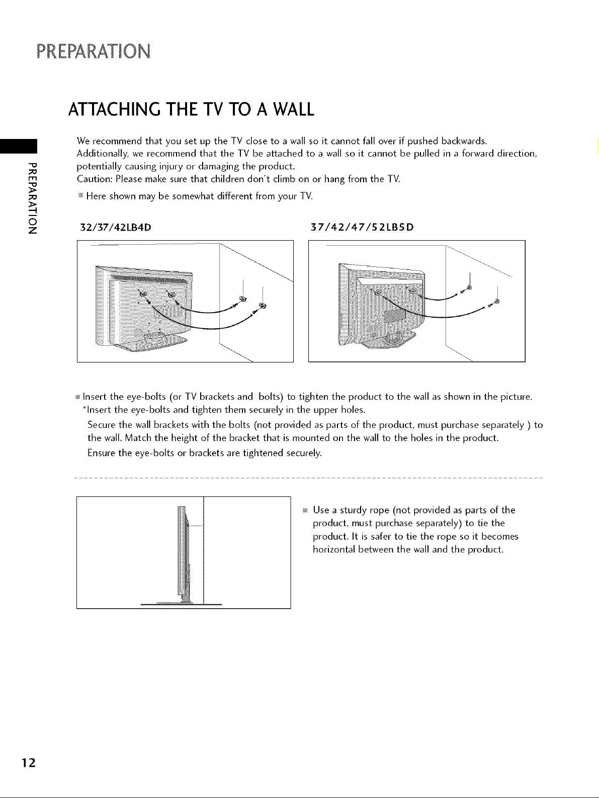
ATTACHING THE TV TO A WALL
We recommend that you set up the TV close to a wall so it cannot fall over if pushed backwards.
Additionally, we recommend that the TV be attached to a wall so it cannot be pulled in a forward direction,
_o
m
_o
potentially causing injury or damaging the product.
Caution: Please make sure that children don't climb on or hang from the TV.
_ Here shown may be somewhat different from your TV.
z
32/37/42LB4D 37/42/47/52LBS D
ii !! !i !! !iiiiii iiiiii i!i!i!ii!ii!!iiiiii!iiiiiiiiiiiiiiiiii!iiii
I I
J
_ Insert the eye-bolts (or TV brackets and bolts) to tighten the product to the wall as shown in the picture.
*Insert the eye-bolts and tighten them securely in the upper holes.
Secure the wall brackets with the bolts (not provided as parts of the product, must purchase separately ) to
the wall. Match the height of the bracket that is mounted on the wall to the holes in the product.
Ensure the eye-bolts or brackets are tightened securely.
_ Use a sturdy rope (not provided as parts of the
product, must purchase separately) to tie the
product. It is safer to tie the rope so it becomes
horizontal between the wall and the product.
12
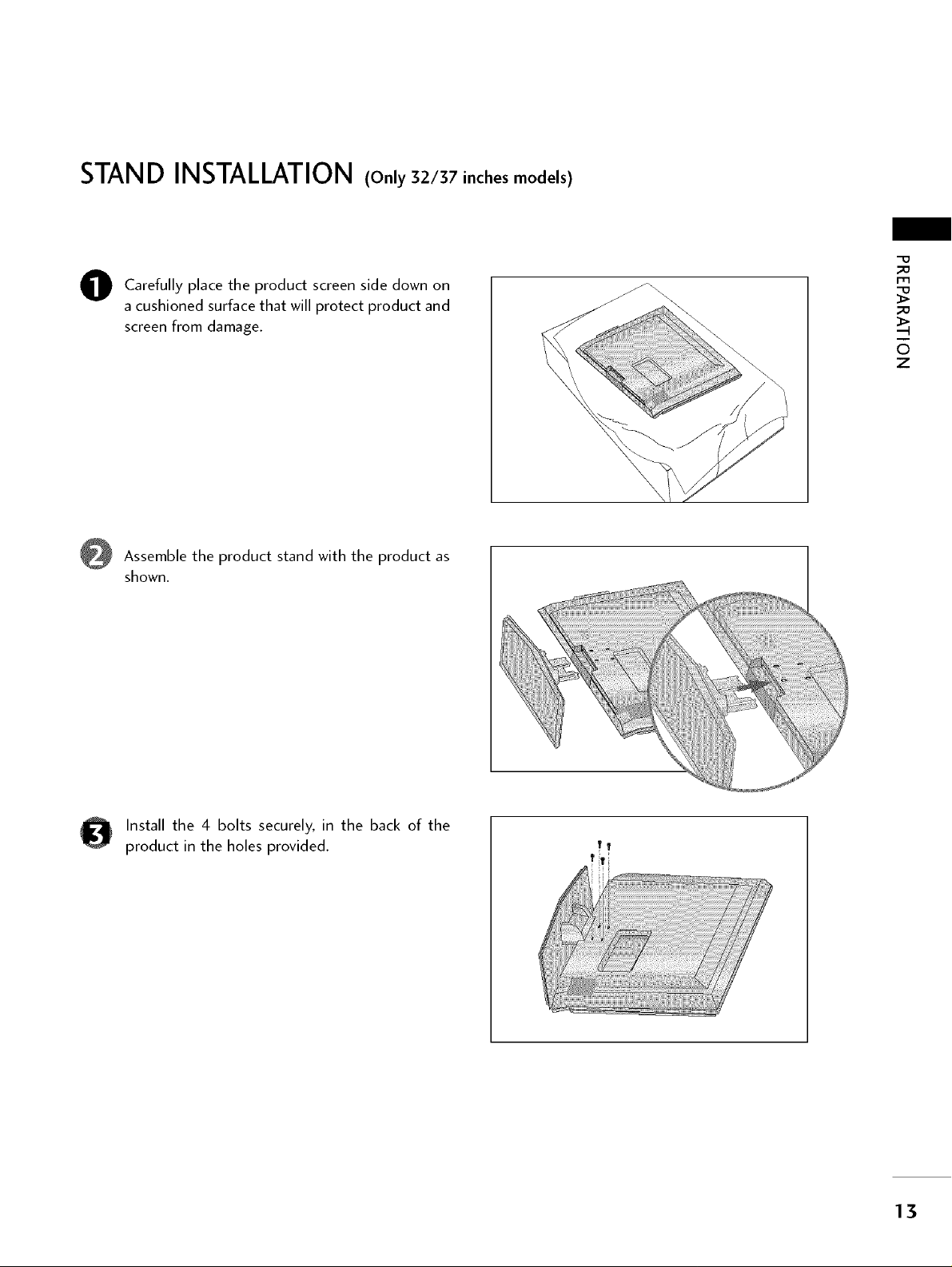
STAND INSTALLATION (Only 32/37 inches models)
Carefully place the product screen side down on
0
a cushioned surface that will protect product and
screen from damage.
Assemble the product stand with the product as
shown.
_o
m
_o
z
Install the 4 bolts securely, in the back of the
product in the holes provided.
TT
13
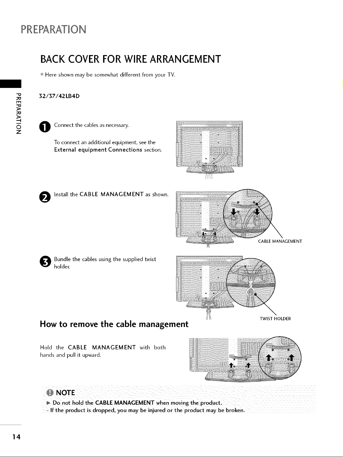
BACK COVERFOR WIREARRANGEMENT
_ Here shown may be somewhat different from your TV.
32/37/42 LB4D
Connect the cables as necessary.
Z
O
To connect an additional equipment, see the
External equipment Connections section.
O Install the CABLE MANAGEMENT as shown.
O undle the cables using the supplied twist
holder.
How to remove the cable management
Hold the CABLE MANAGEMENT with both
hands and pull it upward.
CABLE MANAGEMENT
TWIST HOLDER
14
, If the product is dropped, you maybe injured or the product may be broken,
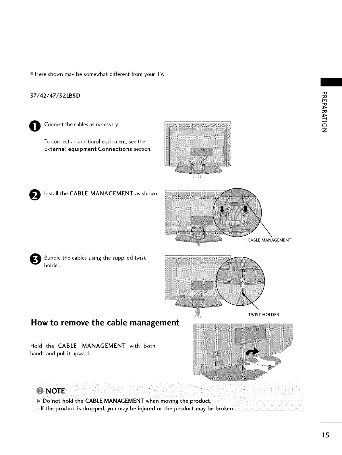
_ Here shown may be somewhat different from your TV.
37/42/47/52LBSD
Connect the cables as necessary.
O
To connect an additional equipment, see the
External equipment Connections section.
O Install the CABLE MANAGEMENT as shown. -.....
O undle the cables using the supplied twist
holder.
m
z
CABLE MANAGEMENT
How to remove the cable management
Hold the CABLE MANAGEMENT with both
hands and pull it upward.
, If the product is dropped, you maybeinjuredortheproductmaybebroken,
TWIST HOLDER
15
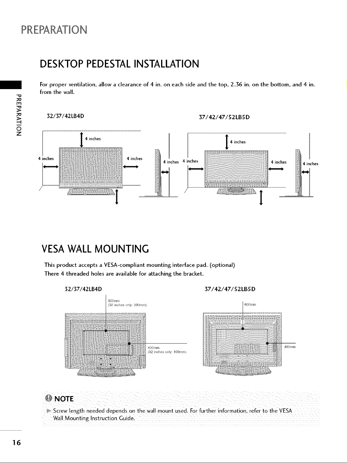
DESKTOPPEDESTALINSTALLATION
For proper ventilation, allow a clearance of 4 in. on each side and the top, 2.36 in. on the bottom, and 4 in.
from the wall.
_D
m
_D
32/37/42LB4D
37/42/47/52LBSD
6
z
4 inches
4 inches
4 inches
4 inches 4 inches
4 inches
VESAWALL MOUNTING
This product accepts a VESA-compliant mounting interface pad. (optional)
There 4 threaded holes are available for attaching the bracket.
16
32/37/42LB4D 37/42/47/S2LBS D
600ram
(32 inches only: 200ram) 600turn
400mm
(32 inches only: lOOmm)
400mm
_, Screw length needed depends on the wa!l mount used. For further information , refer to the VESA
Wall Mounting Instruction Guide,
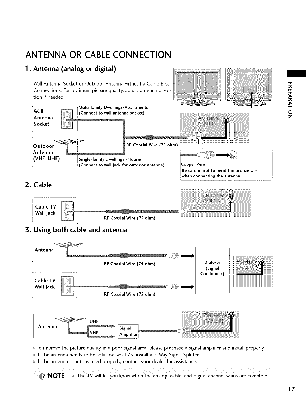
ANTENNA OR CABLECONNECTION
1. Antenna (analog or digital)
Wall Antenna Socket or Outdoor Antenna without a Cable Box
Connections. For optimum picture quality, adjust antenna direc-
tion if needed.
" Multi-family Dwellings/Apartments
Wall onnect to wall antenna socket) I
Antenna
!Antenna .................
I (VHF, UHF) Single-family Dwellings/Houses
/ (Connect to wall jack for outdoor antenna) ICopper Wire
IBe careful not to bend the bronze wire
lwhen connecting the antenna ...........................
2. Cable
Cable TV
Wall Jack
3. Using both cable and antenna
iiiiiiiiiii_:_ii_iiii ililL_i,ii_iii_z!
_o
m
_o
6
7
Antenna
RFCoaxial Wire (75 ohm)
Diplexer
(Signal
Combinner)
Cable TV
Wall Jack
UHF
Antenna
_ To improve the picture quality in a poor signal area, please purchase a signal amplifier and install properly.
_ If the antenna needs to be split for two TV's, install a 2-Way Signal Splitter.
If the antenna is not installed properly, contact your dealer for assistance.
_ NOTE _ The TV wil !!et you know when the analog, cable! and djgita! channel scans are comPlete_
17
EXTERNAL EQUIPMENT SETUP
HD RECEIVERSETUP
This TV can receive Digital Over the-air/Cable signals without an external digital set-top box. However, if you
do receive digital signals from a digital set-top box or other digital external device, reDr to the figure as
shown below,
This TV supports HDCP (High bandwidth Digital Contents Protection) protocol for Digital Contents,
x
z
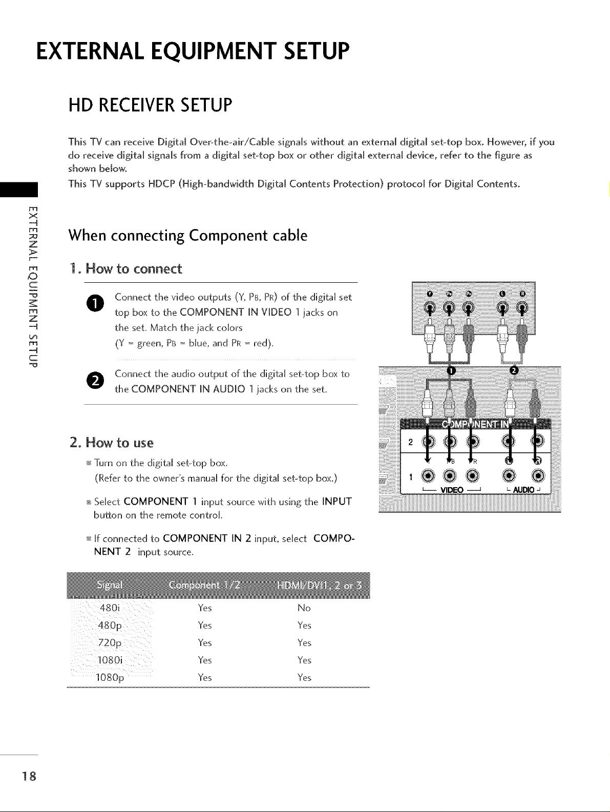
When connecting Component cable
1. How to connect
c
rrl
z
rrl
c
O onnect the video outputs (Y, PB, PR) of the digital set
top box to the COMPONENT IN VIDEO 1 jacks on
the set, Match the jack colors
(Y = green, PB= blue, and PR = red),
O Connect the audio output of the digital set-top box to
the COMPONENT IN AUDIO 1 jacks on the set,
2. How to use
_ Turn on the digital set-top box.
(Refer to the owner's manual for the digital set-top box.)
_ Sdect COMPONENT 1 input source with using the INPUT
button on the remote controk
18
_ if connected to COMPONENT IN 2 input, select COMPO-
NENT 2 input source,
Yes No
Yes Yes
Yes Yes
Yes Yes
Yes Yes
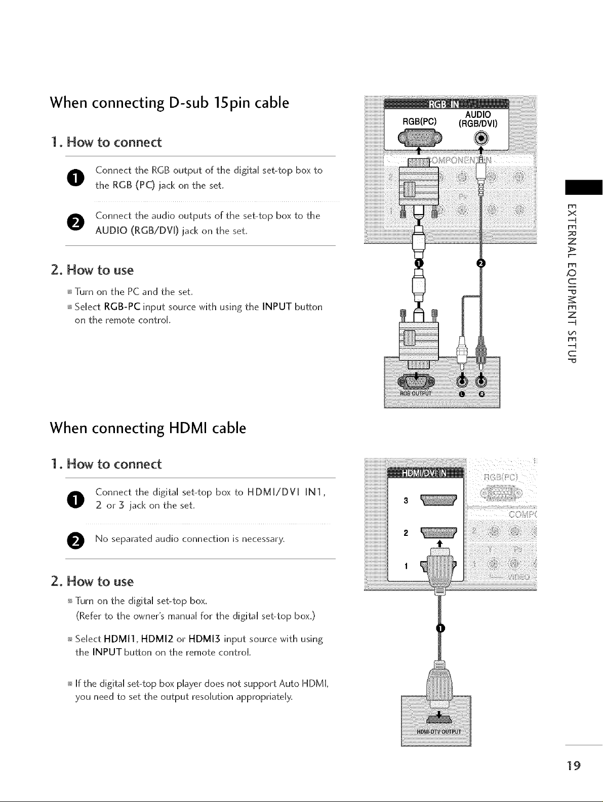
When connecting D-sub 15pin cable
1. Now to connect
O onnect the RGB output of the digita[ set-top box to
the RGB (PC) jack on the set.
O Connect the audio outputs of the set-top box to the
AUDIO (RGB/DV[) jack on the set.
x
-4
Z
2. Now to use
_ Turn on the PC and the set.
_ Se[ect RGB-PC input source wffh using the INPUT button
on the remote control
When connecting HDMI cable
1. Now to connect
O onnect the d@ta[ set-top box to HDMI/DV[ IN1,
2 or 3 jack on the set.
O No separated audio connection is
necessary,
_D
c
Z
-4
-4
c
2. Now to use
Turn on the digital set-top box.
(Refer to the owner's manua[ for the digita[ set-top box.)
Se[ect HDMI1, HDMI2 or HDMI3 input source with using
the INPUT button on the remote control
If the digital set4op box player does not support Auto HDML
you need to set the output resolution appropriately,
19
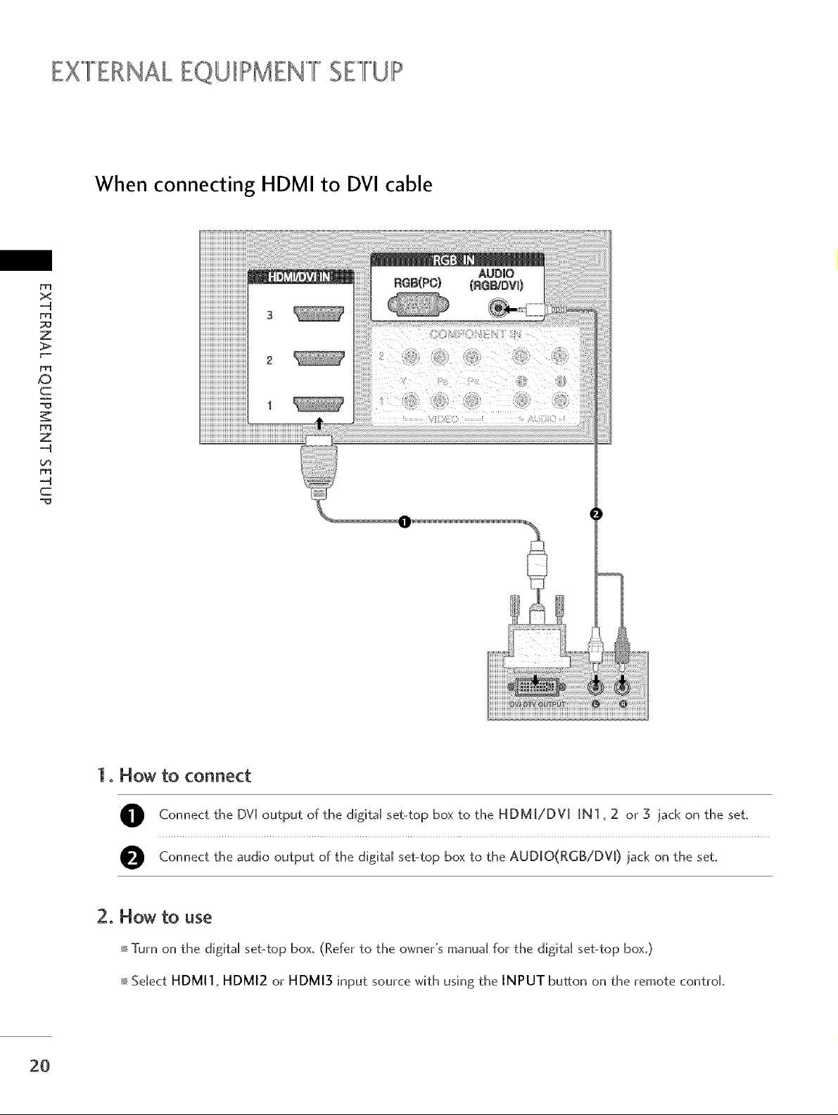
EX""'FERNALEQUIIII!>MEN""'FSETUP
When connecting HDMI to DVI cable
x
z
_D
c
Z
L_
........................1iii:ii::1) ........ _ :ifiiii:iil) ii
c
1. How to connect
O Connect the DVI output of the digital set-top box to the HDMI/DV[ iN1,2 or 3 jack on the set.
O Connect the audio output of the digital set-top box to the AUDJO(RGB/DV[) ]ack on the set.
2O
2. How to use
Turn on the digital set-top box. (Refer to the owner's manuaU for the digital set-top box.)
Sdect HDMI1, HDMI2 or HDMI3 input source with using the INPUT button on the remote controk
DVD SETUP
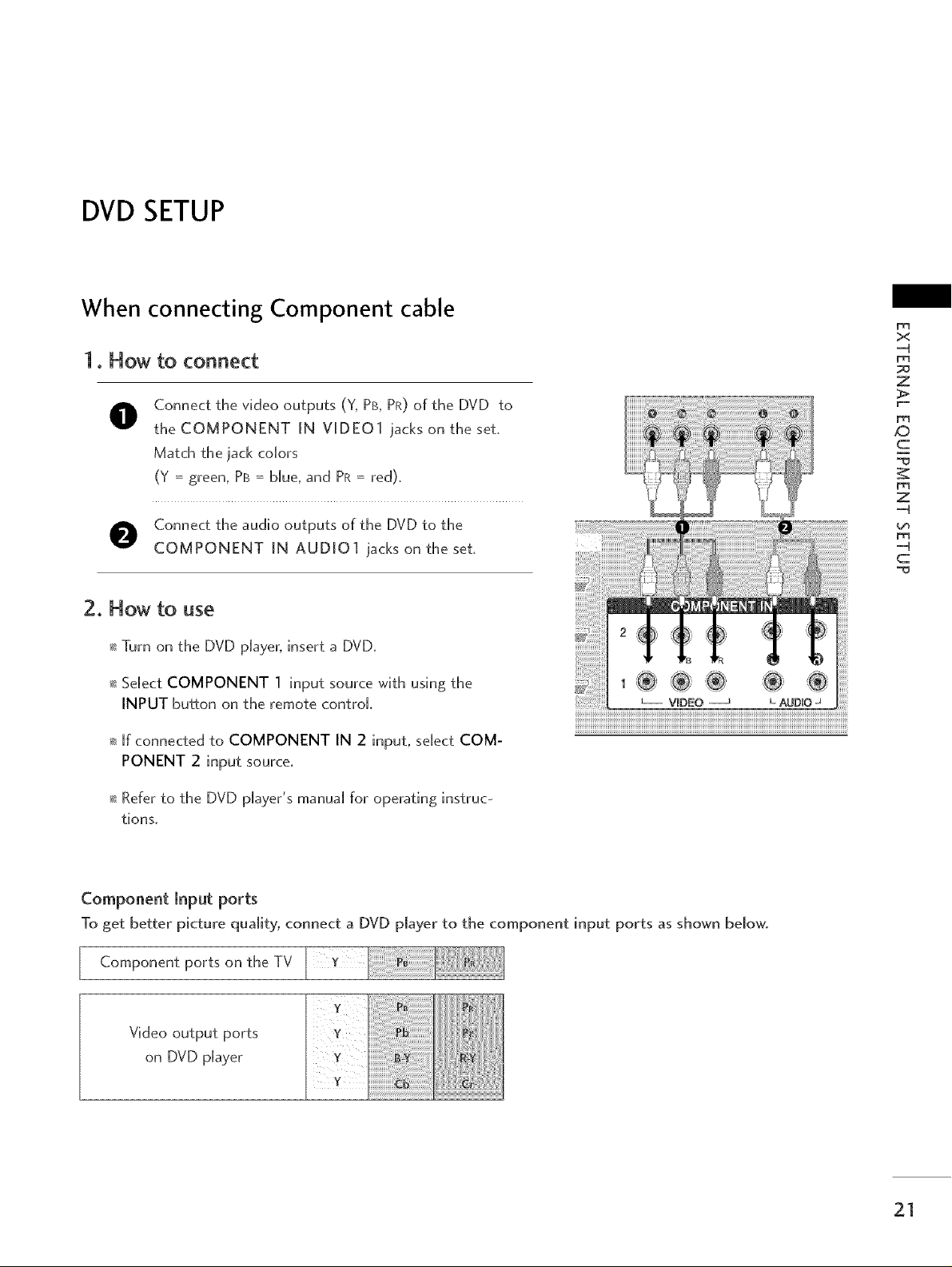
When connecting Component cable
1. How to connect
O onnect the video outputs (Y, PB, PR) of the DVD to
the COMPONENT [N VIDEO1 iacks on the set,
Match the iack colors
(Y = green, PB = blue, and PR = red),
x
-4
z
_D
c
Z
-4
O Connect the audio outputs of the DVD to the
COMPONENT [N AUDIO1 iacks on the set,
2. How to use
_ Turn on the DVD player, insert a DVD,
_ Select COMPONENT 1 input source with using the
INPUT button on the remote control.
_ If connected to COMPONENT IN 2 input, select COM-
PONENT 2 input source.
_ Refer to the DVD player's manual for operating instruc-
tions,
Component Input ports
To get better picture quality, connect a DVD player to the component input ports as shown below.
Component ports on
the TV
-4
c
Video output ports
on DVD player
21
EXTERNALEQUIPMENT SETUP
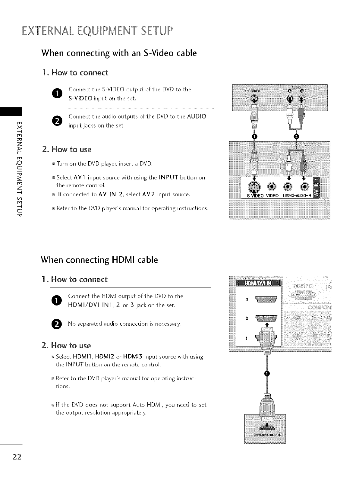
When connecting with an S-Video cable
1. How to connect
O onnect the S-VIDEO output of the DVD to the
S-VIDEO input on the set.
O Connect the audio outputs of the DVD to the AUDIO
x
D_
z
2. Flow to use
input jacks on the set.
_D
c
z
--4
m
c
_ Turn on the DVD player, insert a DVD.
_sSelect AVl input source with using the INPUT button on
the remote control
_ [f connected to AV IN 2, select AV2 input source.
_ Refer to the DVD player's manual for operating instructions.
When connecting HDMI cable
1. Flow to connect
O onnect the HDM[ output of the DVD to the
HDMJ/DV[ IN1,2 or 5 jack on the set.
O No separated audio connection is
necessary,
2. Flow to use
SeUect HDMI1, HDMI2 or HDMI3 input source with using
the INPUT button on the remote control
Refer to the DVD p[ayer's manua[ for operating instruc-
tions,
If the DVD does not support Auto HDM[, you need to set
the output resolution appropriately,
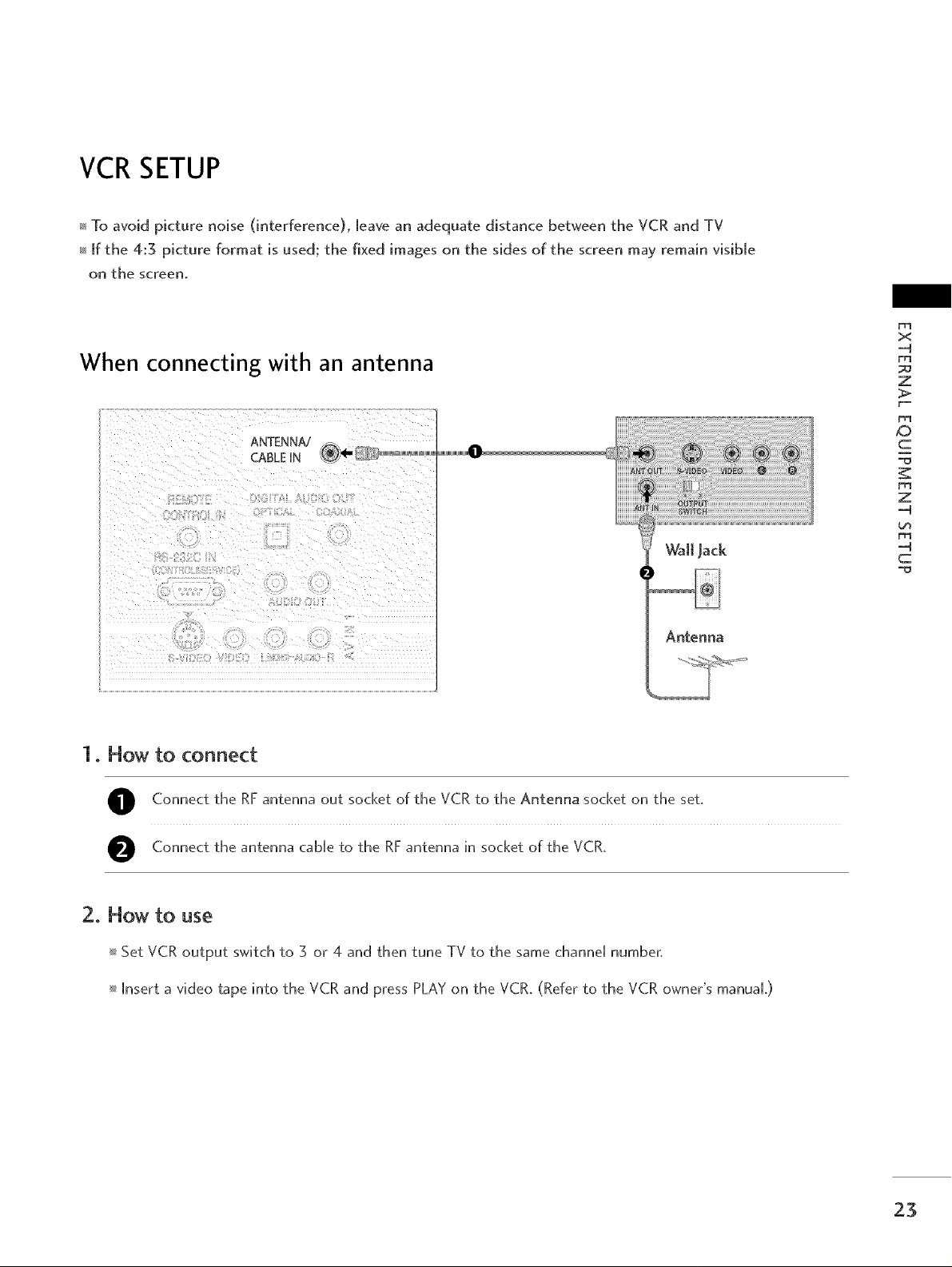
VCR SETUP
To avoid picture noise (interference), leave an adequate distance between the VCR and TV
If the 4:3 picture format is used; the fixed images on the sides of the screen may remain visible
on the screen,
When connecting with an antenna
x
-4
r_
z
1. How to connect
Connect the RF antenna out socket of the VCR to the Antenna socket on the set,
Connect the antenna cable to the RF antenna in socket of the VCR,
ANTENNA/
CABLE HN
Antenna
_D
c
Z
-4
-4
c
2. How to use
Set VCR output switch to 3 or 4 and then tune TV to the same channel number,
[nsert a video tape into the VCR and press PLAY on the VCR, (Refer to the VCR owner's manuaL)
23
EX""'FERNALEQUIIII!>MEN""'FSETUP
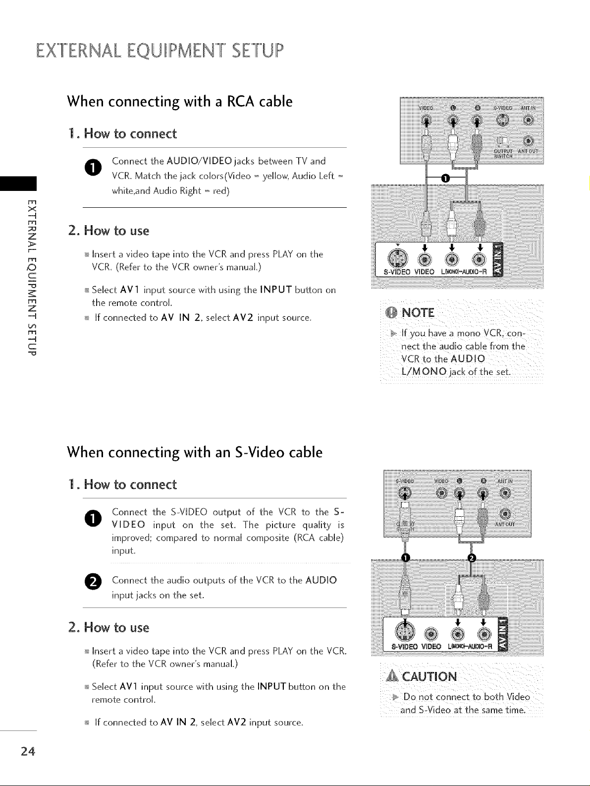
When connecting with a RCA cable
1. How to connect
Connect the AUDJO/V[DEO]acks between TV and
VCR. Match the lack colors(Video = yellow, Audio Left =
whffe,and Audio Right = red)
x
-4
z
_O
c
rT1
z
-4
-4
c
2. How to use
mInsert a video tape into the VCR and press PLAY on the
VCR. (Refer to the VCR owner's manuaL)
mSelect AV1 input source wffh usMg the INPUT button on
the remote control.
m [f connected to AV IN 2, select AV2 input source.
If you have a mono VCR. con-
nect the audio came from _he
VCR to the AUDIO
L/MONO jack of the set
When connecting with an S-Video cable
1. Flow to connect
Connect the S-VIDEO output of the VCR to the S-
O
VIDEO input on the set. The picture qua[fly is
improved; compared to normal composffe (RCA cable)
input.
Connect the audio outputs of the VCR to the AUDIO
Mput iacks on the set.
2. Flow to use
mInsert a video tape into the VCR and press PLAY on the VCR.
(Refer to the VCR owner's manuaL)
mSelect AVl input source wffh using the INPUT button on the
remote control
m [t:connected to AV IN 2, select AV2 input source.
CAUTION
and S:V[deo at €he same time:
24
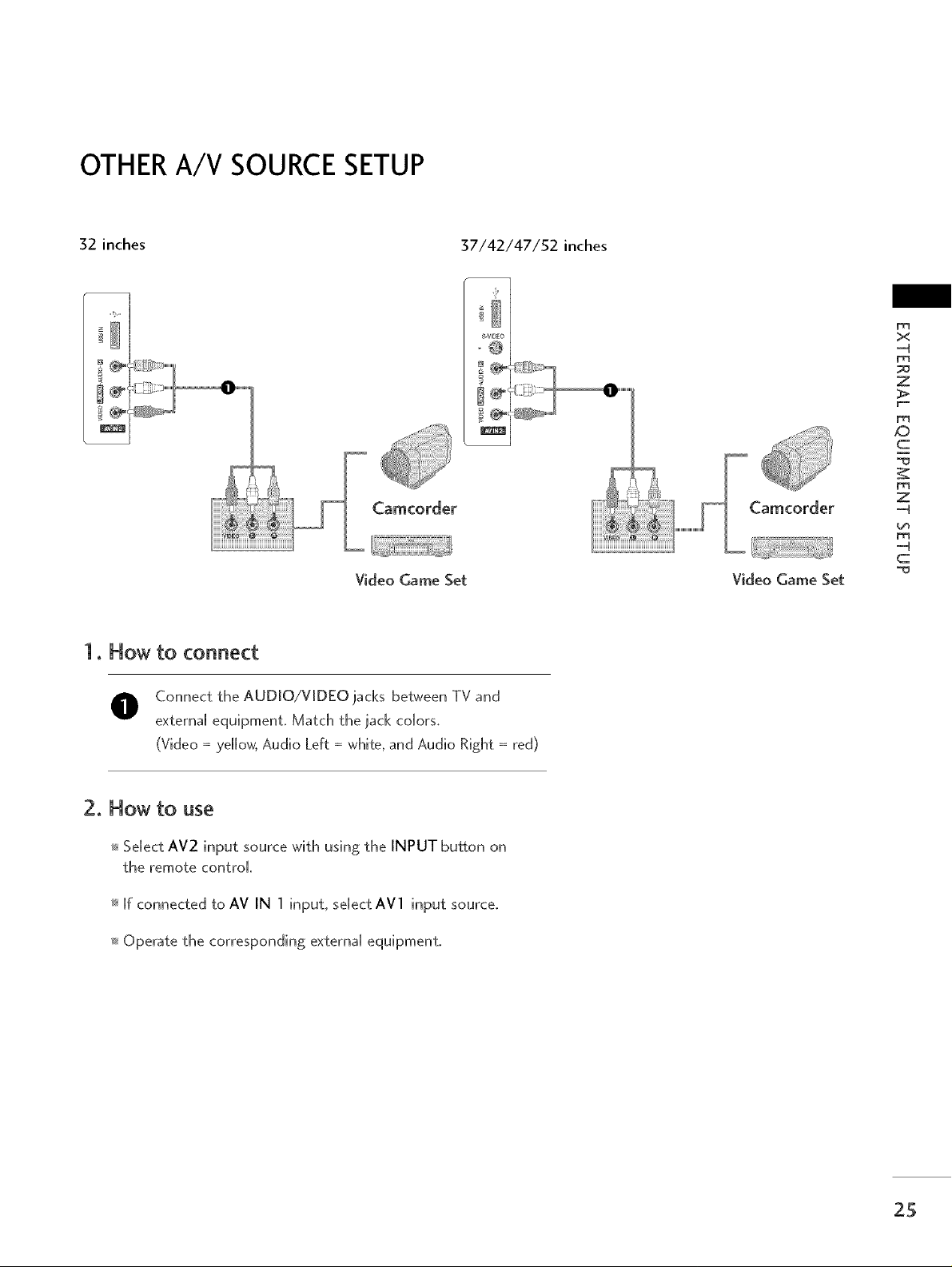
OTHERA/V SOURCESETUP
32 inches
Video Game Set Video Game Set
x
-4
Z
ID
c
Z
-4
-4
c
1. How to connect
O Connect the AUDIO/VIDEO jacks between TV and
external equipment, Match the jack colors,
(Video =ye[[ow, Audio Left = whffe, and Audio Right = red)
2. How to use
Select AV2 input source wffh using the INPUT button on
the remote control
[f connected to AV IN 1 input, se[ect AVl input source,
Operate the corresponding externa[ equipment,
25
EX""'FERNALEQUIIII!>MEN""'FSETUP
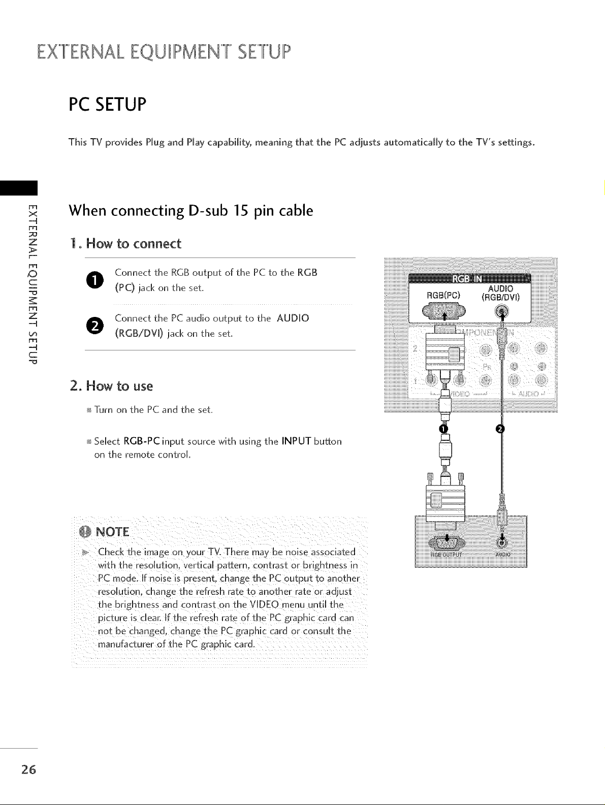
PC SETUP
This TV provides PJug and Hay capability, meaning that the PC adjusts automaticaJJy to the TV's settmgso
D1
x
-4
po
z
When connecting D-sub 15 pin cable
1. How to connect
_D
c
Z
-4
-4
c
Connect the RGB output of the PC to the RGB
(PC) lack on the set.
Connect the PC audio output to the AUDIO
(RGB/DV[) lack on the set.
2. How to use
Turn on the PC and the set.
Select RGB-PC input source with using the INPUT button
on the remote control
Check the image on your TVoThere ma) be noise associated
with the resolution, vertical pattern, contrast or brightness m
PC mode. If noise is present, change the PC output to another
resolution, change the refresh rate to another rate or adiust
the brightness and contrast on the VIDEO menu until the
picture is dear: If the refresh rate of the PC graphic card can
not be changed, change the PC graphic card or consuUt the
manufacturer of the PC graphic card.
26
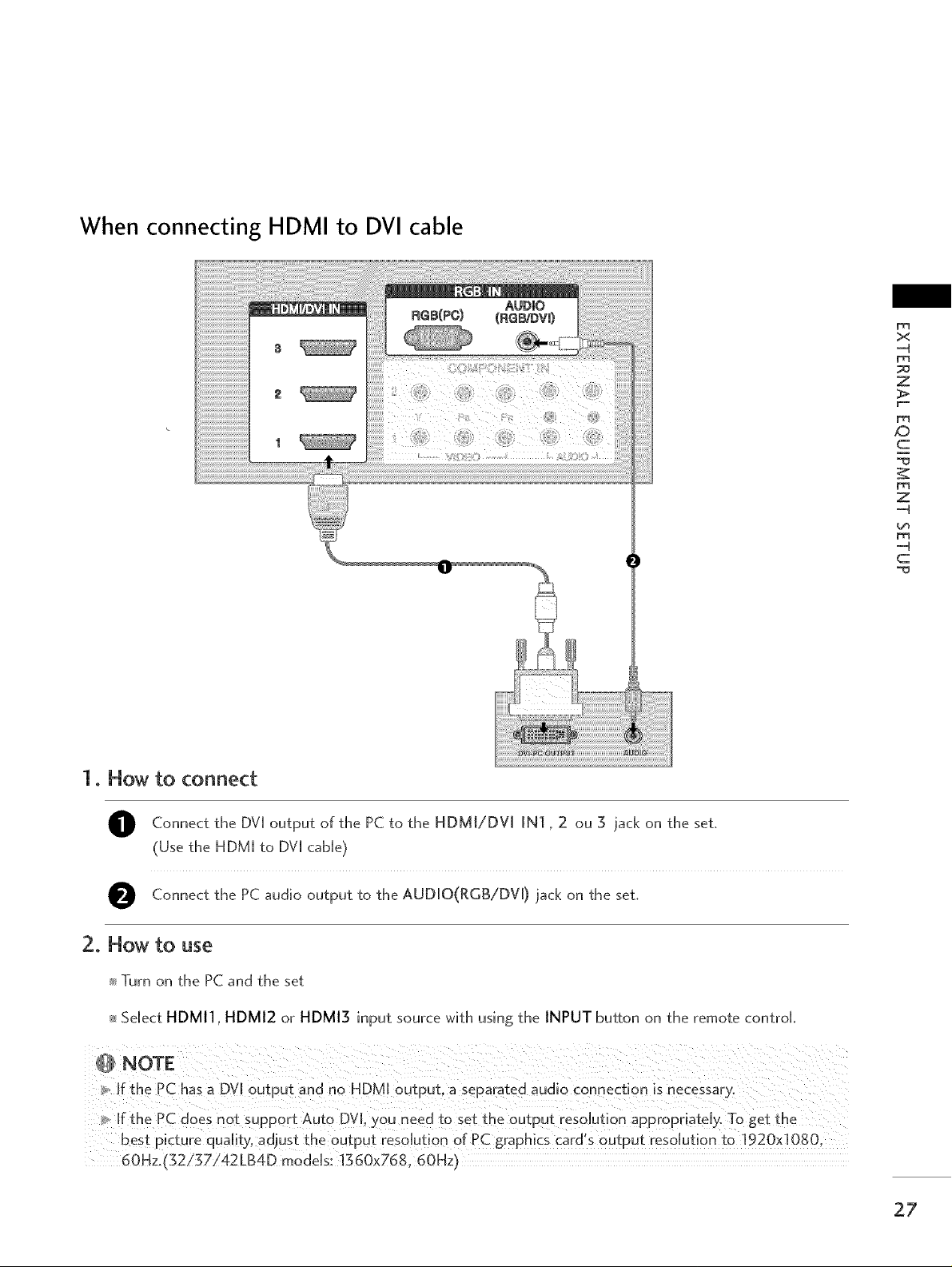
When connecting HDMI to DVI cable
x
-4
z
XD
c
Z
-4
-4
c
1. How to connect
O Connect the DV[ of the PC to the HDMI/DV[ IN] 2 3 iack the set.
(Use the HDM[ to DV[ cable)
O Connect the PC audio to the AUD[O(RGB/DV D the set.
output
output jack
2. How to use
_ Turn on the PC and the set
_ Select HDMI1, HDMI2 or HDMI3 input source with using the INPUT button on the remote control
NOTE
If the PC has a DV[ output and no HDMm output_ a separated audio connection is necessary°
ffthe PC does not support Auto DVI, )ou need ±o set the output resolution appropriately. To get the
best picture quality, adjust the output resolution of PC graphics card's output resolution to 1920x1080.
60Hz.{'52/g7i42LB4D models: 1360x768.60Hz I
ou on
on
27
EXFERNAk EQUIIIPMENIIIFSEIlliUIIh,,
ir I ,,,,,,,i,,,,,,,
x
....q
z
,.0
c
z
....q
-4
c
Depending on the graphics card_ DOS mode ma)
not work ira HDM[ to DVI CaMe is in use.
Check the image on your TV_ There may be noise
associated _ ith the resoJution_ vertical pattern.
contrast or brightness in PC mode. ff noise is
present, change the PC output to another resoJu-
t[om change the refresh rate to another rate or
adjust the brightness and contrast on the PIC-
TURE menu unti[ the picture is dear: If the refresh
rate of the PC graphic card can not be changed,
change the PC graphic card or consult the manu-
facturer of the PC graphic card,
_, Avoid keeping a fixed image on the screen for a
[ong period of time. Ths fixed mage may become
permanently imprinted on the screen
The s) nchronizat[on input form for Horizontal and
Verti caJ frequencies is separate.
28
 Loading...