

LG 520SI, CB550BN ADJUSTMENT
ADJUSTMENT
- 12 -
GENERAL INFORMATION
All adjustment are thoroughly checked and corrected
when the monitor leaves factory, but sometimes several
minor adjustment may be required.
Adjustment should be following procedure and after
warming up for a minimum of 30 minutes.
• Alignment appliances and tools.
- Programmable Signal Generator.
(eg. VG-819 made by Astrodesign Co.)
- E(E)PROM with each mode data saved.
- Digital Voltmeter.
- White Balance Meter.
- Luminance Meter.
ADJUSTMENT PROCEDURE & METHOD
Set Contrast ( ) and Brightness ( ) volume to max
position.
1. Adjustment for B+Voltage
1) Display cross hatch pattern at Mode 1.
2)
Adjust VR901 to 14±0.2Vdc at D922 cathode voltage.
2. Adjustment for High Voltage
1) Display cross hatch pattern at Mode 1.
2)
Adjust D804 cathode voltage to 63±0.2Vdc with VR801.
3. Adjustment for Screen Image (Factory Mode)
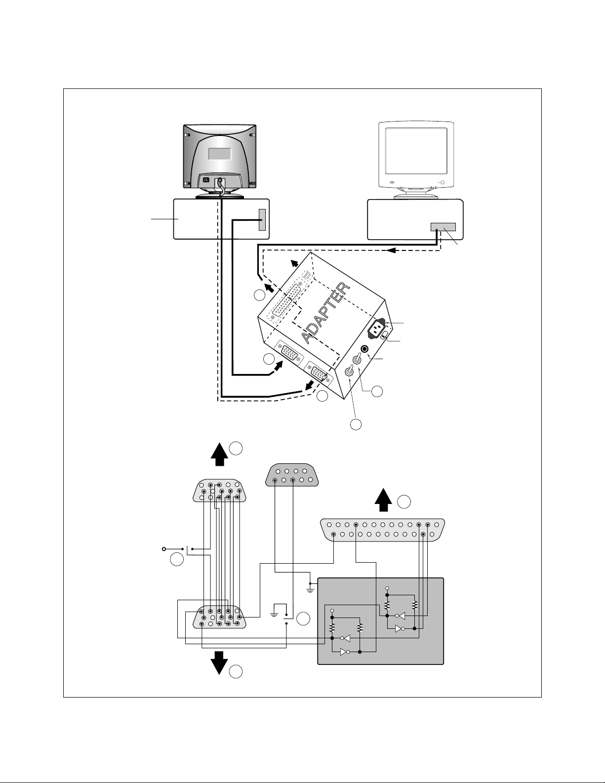
Install adaptor and cable for adjustment such as figure 1
and run alignment program on DOS for IBM compatible
PC.
1) Set ST Switch to OFF of the adaptor.
(Refer to see Figure 1.)
2) Display cross hatch pattern at Mode 1.
3) Adjust horizontal size ( ) with H-SIZE in the
alignment program or +, – buttons on the monitor to
270
±1mm.
4) Adjust horizontal position ( ) with H-POSI in the
alignment program or +, – buttons on the monitor to
center of the screen.
5) Adjust vertical size ( ) with V-SIZE in the
alignment program or +, – buttons on the monitor to
195
±1mm.
6) Adjust vertical position ( ) with V-POSI in the
alignment program or +, – buttons on the monitor to
center of the screen.
7) Adjust side-pincushion ( ) with S-PCC in the
alignment program or +, – buttons on the monitor to
be the best condition.
8) Adjust trapezoid ( ) with TRAPEZOID in the
alignment program or +, – buttons on the monitor to
be the best condition.
9) Display from Mode 2 to Mode 5 and repeat above
adjustment.
4. Adjustment for White Balance and Luminance.
1) Set the White Balance Meter.
2) Demagnetize CDT with the demagnetizer. (external
degaussing coil).
3) Adjust H x V size to 270
±2mm x 195±2mm.
4) Display color 0,0 pattern at Mode 1.
5) Set Brightness ( ), Contrast ( ) volume to
max position.
6) Set VR302 (G-BIAS) and VR312 (R-BIAS) to min
and VR322 (B-BIAS) to center position.
7) Adjust Screen control on the FBT to 0.9~1FL of the
raster luminance.
8) Adjust VR302 (G-BIAS) and VR312(R-BIAS) to
x=0.283
±0.01 and y=0.298±0.01.
9) Adjust Screen control on the FBT to 0.3~0.4FL of the
raster luminance.
10)
Display color 15,0 box pattern (70 x 70mm) at Mode 1.
11)
Set Brightness ( ), Contrast ( ) volume to
max position.
12)
Adjust VR311 (G-DRIVE) to 55±1FL of the box
pattern luminance.
13)
Adjust VR301 (R-DRIVE) and VR321 (B-DRIVE) to
x=0.283
±0.003 and y=0.298±0.003.
14)
Set Brightness ( ), Contrast ( ) volume to
max position.
15)
Display color 15,0 full white patten at Mode 1.
16)
Adjust VR503 (ABL) to 33±1FL of the luminance.
5. Adjustment for Focus.
1) Display H character in the full screen at Mode 4.
2) Adjust two Focus control on the FBT that should be
the best condition.
E
- 13 -
Video
Figure 1. CABLE CONNECTION
Signal Generator
Monitor to be
adjusted
Control Line
C
PARALLEL
A
Not used
VGS
RS232C
MONITOR
ST
V-SYNC
IBM
Compatible PC
220
POWER
Power LED
Parallel Port
Power inlet (required)
Power Select Switch
(110V/220V)
5V
15
5
OFF ON
F
E
B
F
ST Switch
V-Sync On/Off Switch
(Switch must be ON.)
A
69
5
10
11
6
1
ON
OFF
1
C
13
25
5V
4.7K
E
5V
4.7K
74LS06
4.7K
74LS06
1
14
B
 Loading...