

LG 50PZ570, 32LV3710-TB Owner’s Manual

OWNER’S MANUAL
LED LCD TV / PLASMA TV
Please read this manual carefully before operating the
set and retain it for future reference.
www.lg.com
LICENSES
2
LICENSES
Supported licenses may differ by model. For more information about licenses, visit www.lg.com.
<Analogue TV>
Manufactured under license from Dolby Laboratories. “Dolby” and the double-D
symbol are trademarks of Dolby Laboratories.
<Digital TV>
Manufactured under license from Dolby Laboratories. “Dolby” and the double-D
symbol are trademarks of Dolby Laboratories.
HDMI, the HDMI logo and High-Definition Multimedia Interface are trademarks or
registered trademarks of HDMI Licensing LLC.
ENGLISH
ENGLISH
ENG
ENG
ABOUT DIVX VIDEO: DivX® is a digital video format created by DivX, LLC, a
subsidiary of Rovi Corporation. This is an official DivX Certified® device that plays
DivX video. Visit divx.com for more information and software tools to convert your
files into DivX video.
ABOUT DIVX VIDEO-ON-DEMAND: This DivX Certified® device must be registered in order to play purchased DivX Video-on-Demand (VOD) movies. To obtain
your registration code, locate the DivX VOD section in your device setup menu. Go
to vod.divx.com for more information on how to complete your registration.
“DivX Certified® to play DivX® and DivX Plus® HD (H.264/MKV) video up to 1080p
HD including premium content.”
“DivX®, DivX Certified®, DivX Plus® HD and associated logos are trademarks of
Rovi Corporation or its subsidiaries and are used under license.”
“Covered by one or more of the following U.S. patents :
7,295,673; 7,460,668; 7,515,710; 7,519,274”
NOTE
Image shown may differ from you TV.
y
Your TV's OSD(On Screen Display) may differ slightly from that shown in this manual.
y
The available menus and options may differ from the input source or product model that you are
y
using.

LICENSES
3
ENGENGLISH

TABLE OF CONTENTS
4
TABLE OF CONTENTS
ENGLISH
ENG
2 LICENSES
6 ASSEMBLING AND PREPAR-
ING
6 Unpacking
11 Separate purchase
12 Parts and buttons
20 Lifting and moving the TV
20 Setting up the TV
20 - Attaching the stand
24 - Mounting on a table
26 - Mounting on a wall
27 - Wall mounting bracket installation
28 - Tidying cables
29 - Not using the Desk-Type Stand
30 REMOTE CONTROL
33 Magic Motion Remote Control Functions
34 - Installing RF Dongle
34 - Registering Magic Motion Remote Con-
trol
34 - How to use Magic Motion Remote Con-
trol
35 - Precautions to Take when Using the
Magic Motion Remote Control
35 WATCHING TV
35 Connecting to an antenna
35 - Connecting an antenna
36 Turning the TV on for the first time
36 Watching TV
37 Accessing Home menu
38 Managing programmes
38 - Automatically setting up programme
38 - Manually setting up programme (In
digital mode)
39 - Manually setting up programme (In
analogue mode)
40 - Editing your programme list
41 - Using favourite programmes
42 Using additional options
42 - Adjusting aspect ratio
43 - Changing AV modes
44 - Using the input list
45 Using the quick menu
46 ENTERTAINMENT
46 Network Connection
46 - Connecting to a wired network
47 - Connecting to a wireless network
49 - When a security code is already set
52 - Network Status
53 Premium Account Function
55 LG Apps Function
55 - Registration LG Apps
56 - Sign in with LG Apps account
56 - Using LG Apps
57 - Using My Apps
58 Web Browser Function
58 - Using Web Browser
59 - Browsing Favourite Websites
60 - Browsing Websites by Directly Entering
Address
60 - Viewing Visited Website List
61 Smart Share Function
61 - Connecting USB storage devices
62 - Connecting DLNA DMP (Digital Living
Network Alliance, Digital Media Player)
65 - Connecting DLNA DMR (Digital Living
Network Alliance, Digital Media Render)
66 - Browsing files
67 - Viewing Videos
70 - DivX® VOD Guide
71 - Viewing Photos
73 - Listening to music
75 Media Link Function
75 - Media Link Connection
76 - Using Media Link
76 - Viewing Movies
77 - Using Music Section
77 - Using TV Programme Section
78 - Installing Plug-Ins
79 DVR Function
79 - Precautions when using the USB De-
vice
80 - Timeshift (PAUSE & REPLAY OF LIVE
TV)
83 - RECORDING
84 - SCHEDULE
87 - RECORDED TV
90 EPG (Electronic Programme Guide) Func-Programme Guide) Func- Guide) Func-Func-
tion (In digital mode)
90 - Switch on/off EPG
90 - Select a programme
91 - NOW/NEXT Guide Mode
91 - 8 Day Guide Mode
91 - Date Change Mode
91 - Extended Description Box
92 MHEG (Multimedia and Hypermedia In-
formation coding Expert Group) (In digital
mode)
92 - Teletext Within Digital Service
92 - Teletext in Digital Service
93 - Switch on/off MHEG

TABLE OF CONTENTS
5
93 - Select a programme
93 - Programme Listing Mode
93 - NOW/NEXT Guide Mode
94 3D IMAGING (ONLY 3D MOD-
ELS)
94 3D Technology
95 When using 3D Glasses
96 3D Imaging viewing range
96 Viewing 3D Imaging
97 - Setting 3D Imaging
98 CUSTOMIZING TV SETTINGS
98 The SETUP Menu
99 Customizing Settings
99 - SETUP Settings
100 - PICTURE Settings
107 - AUDIO Settings
111 - TIME Settings
112 - LOCK Settings
113 - OPTION Settings
117 - NETWORK Settings
118 - SUPPORT Settings
119 MAKING CONNECTIONS
120 Connection Overview
121 Connecting to a HD receiver, DVD, or
VCR player
121 - HDMI connection
122 - DVI to HDMI Connection
123 - Component Connection
124 - Composite Connection
125 Connecting to a PC
125 - HDMI Connection
126 - DVI to HDMI Connection
126 - RGB Connection
128 Connecting to an Audio System
128 - Digital Optical Audio Connection
129 Connecting to Headphone Connection
129 Connecting to a USB
130 Connecting the Wireless Media Box
130 SIMPLINK Connection
131 - Activating and Using the SIMPLINK
menus
132TELETEXT
132 Switch On/Off
132 Simple Text
132 - Page selection
132 Top Text
132 - Block / Group / Page Selection
132 - Direct Page Selection
133 Fastext
133 - Page selection
133 Special Teletext Function
134MAINTENANCE
134 Updating the TV firmware
135 Cleaning Your TV
135 - Screen and frame
135 - Cabinet and stand
135 - Power cord
136 Preventing “Image burn” or “Burn-in” on
your TV screen
137TROUBLESHOOTING
139SPECIFICATIONS
150IR CODES
151EXTERNAL CONTROL DEVICE
SETUP
151 RS-232C Setup
151 Type of connector;
D-Sub 9-Pin Male
152 RS-232C Configurations
153 Communication Parameters
153 Command reference list
154 Transmission / Receiving Protocol
159OPEN SOURCE LICENSE
160 - GNU GENERAL PUBLIC LICENSE
164 - GNU Lesser General Public License
170 - Mozilla Public License 1.1 (MPL 1.1)
176 - Apache License Version 2.0
179 - MIT license
181 - Expat license
181 - The FreeType Project LICENSE
183 - JPEG license
183 - OpenSSL License
185 - zlib/libpng License
185 - Portmap license
186 - Pixman license
186 - X.net license
187 - BSD license
188 - RSA Data Security license
189 - JSON license
189 - MS92 license
ENGENGLISH
ASSEMBLING AND PREPARING
6
ASSEMBLING AND PREPARING
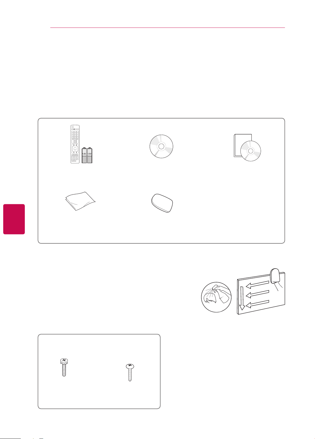
Unpacking
Check your product box for the following items. If there are any missing accessories, contact the local
dealer where you purchased your product.
The illustrations in this manual may differ from the actual product and item.
ENGLISH
ENG
Remote control and batteries
(AAA)
Polishing cloth1
(Depending on model)
1 Gently wipe the spots on the cabinet with the polishing cloth.
2 Wipe spots on the exterior only with the cleansing cloths.
Do not wipe roughly when removing stains. Excessive pressure
may cause scratches or discolouration.
For cleaning front frame, please slowly wipe in one direction
after spraying water 1-2 times on cleansing cloths. Please
remove excessive moisture after cleaning. Excessive moisture
may cause water stains on the frame.
Nero MediaHome 4 Essentials CD
Cleansing Cloths (Mitt)
(Depending on model)
Owner’s manual
2
Water
Only 32/37/42/47/55LV37
x 8
M4 x 12
Screw for assembly Screw for fixing
**
(Only 32/37LV37**)
ASSEMBLING AND PREPARING
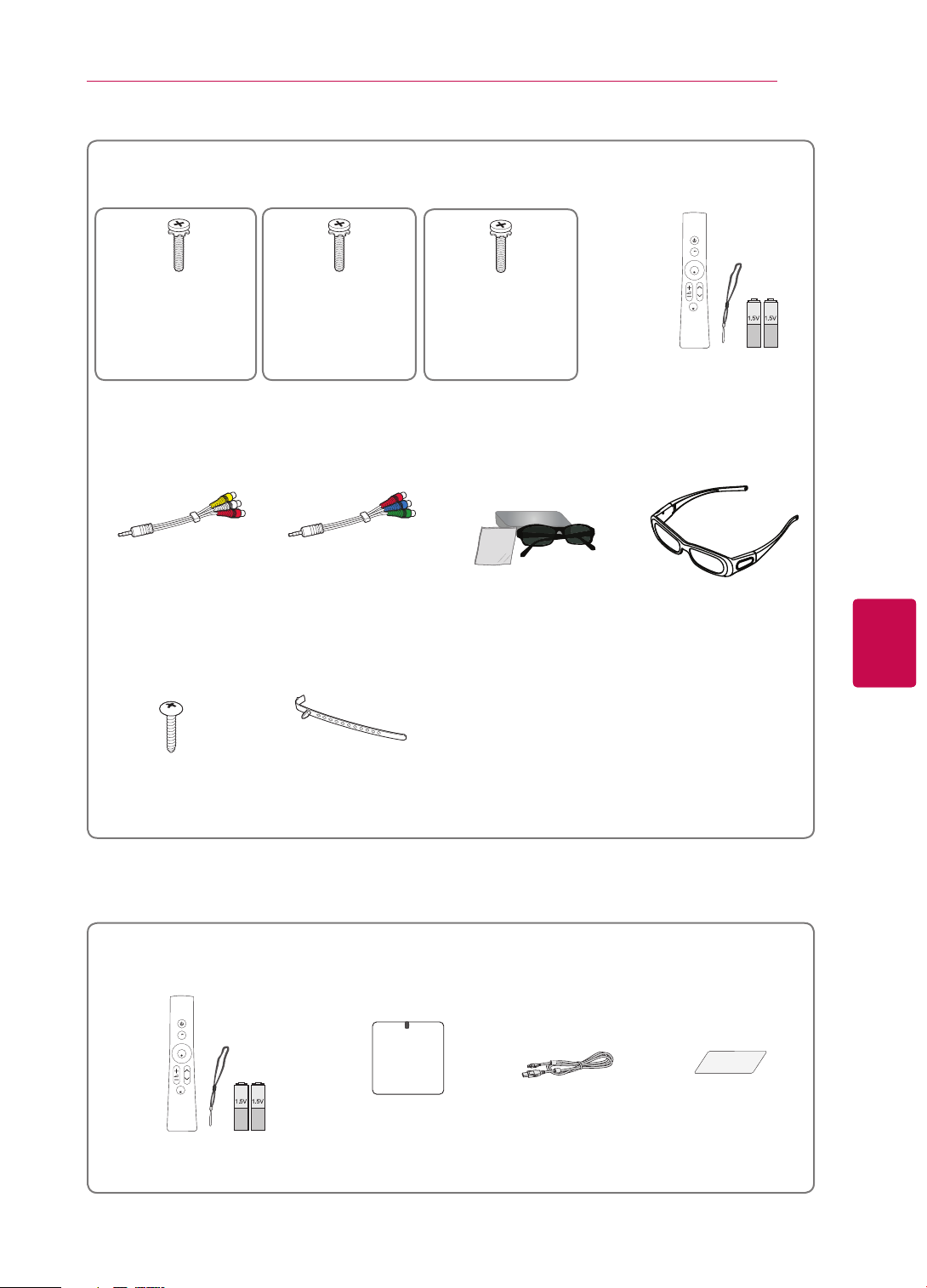
Only 32/37/42/47/55LV55**, 32/42/47/55LW57**, 42/47/55/65LW65**, 47/55LW77**, 47/55LW95**,
47/55LW98
**
7
x 8
M4 x 16
(Only 47/55LW95**,
47/55LW98**)
x 8
M4 x 12
(Except for
47/55LW95**,
65LW65**,
M4 x 16
(Only 65LW65**)
x 9
47/55LW98**)
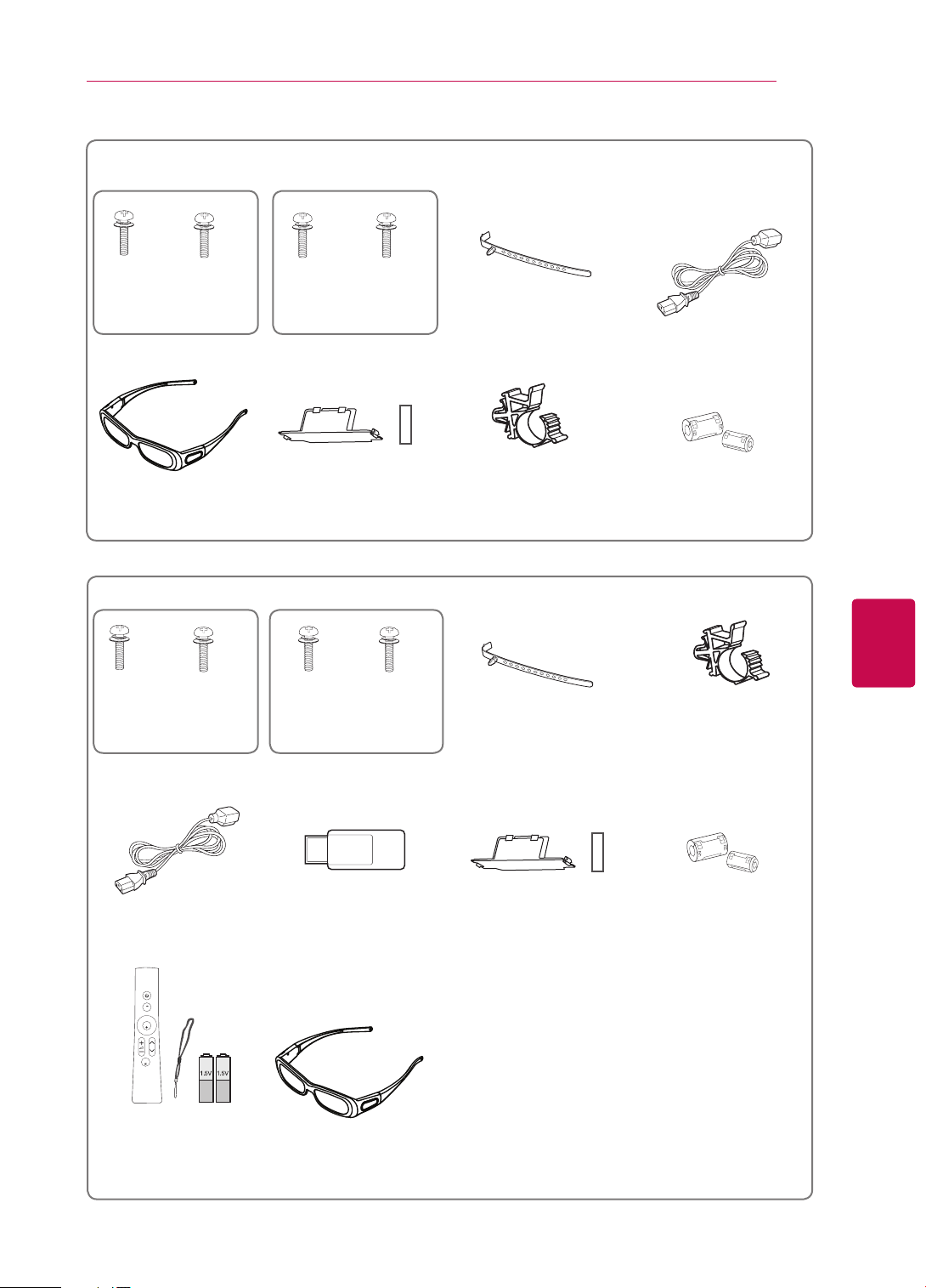
Screw for assembly
Composite gender cable Component gender cable FPR 3D Glasses1
(Only 32/42/47/55LW57**,
42/47/55/65LW65**,
47/55LW98**)
Home
OK
P
MUTE
Magic Motion Remote
Control,
Strap, Batteries (AA)
(Only 47/55LW77**,
47/55LW95**, 47/55LW98**)
3D Glasses (AG-S250)
(Only 47/55LW77**)
ENGENGLISH
Screw for fixing
(Only 32/37LV55**,
Cable holder
(Depending on model)
32LW57**)
1 The number of 3D glasses may differ depending on the country.
This feature is not available for all country.
Only 32/37/42/47/55LV37**, 32/37/42/47/55LV55**, 32/42/47/55LW57**, 42/47/55/65LW65
Home
OK
P
MUTE
Magic Motion Remote Control,
RF Dongle
RF Donglea Cable Velcro
Strap, Batteries (AA)
**
ASSEMBLING AND PREPARING
8
ENGLISH
ENG
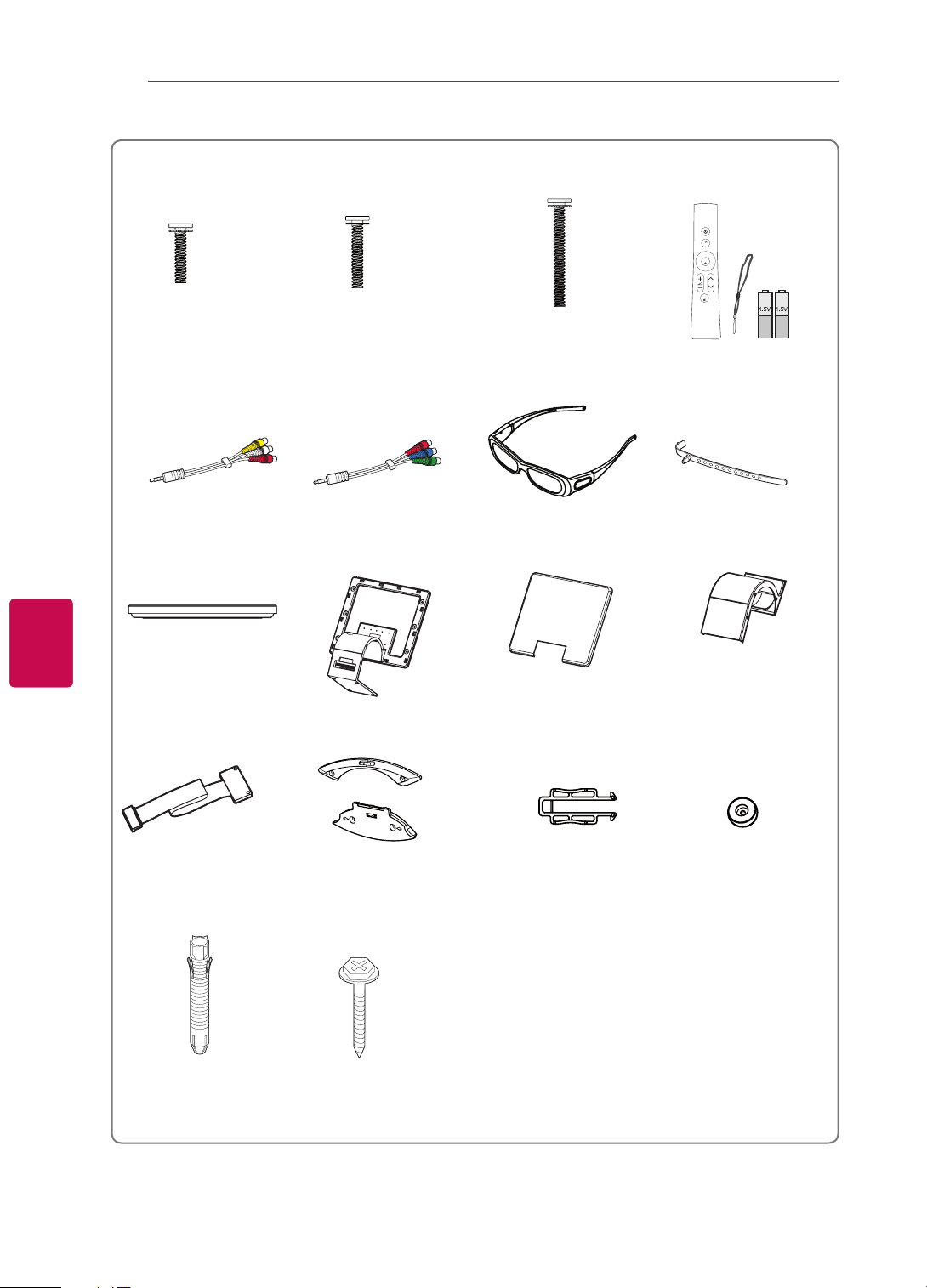
Only 47/55LZ96
M3 x 6
x 4
**
x 6
M4 x 7 M4 x 14
Bolts for stand and wall mounting bracket assembly
Composite gender cable Component gender cable
x 6
3D Glasses (AG-S250)
Home
OK
P
MUTE
Magic Motion Remote
Control,
Strap, Batteries (AA)
Cable holder
Stand Base Stand Body Stand Rear Cover Display Link Cable Cover
x 2
Display Link Cable
(stand type and wall
mounting type)
Wall Mounting Bracket
(one for the set and one for
the wall)
Wall Mounting Bracket
Pushpin
Set Protection Bracket
x 2
x 2
Wall Anchor Screw
x 2
ASSEMBLING AND PREPARING
9
Only 50/60PZ57
**
x 4
M4 x 26 M5 x 14.5
(Only 50PZ57**)
Screw for assembly Cable holder Power Cord
3D Glasses
(AG-S250)
Only 50/60PZ95
**
x 4
x 3
x 3
x 4
M4 x 28
M5 x 24
(Only 60PZ57**)
Protection cover,
Protection Tape
x 4
x 3
Power Cord holder Ferrite core
(Depending on model)
ENGENGLISH
x 4
M4 x 26 M5 x 14.5
M4 x 28
M5 x 14.5
(Only 50PZ95**) (Only 60PZ95**) Cable holder Power Cord holder
Screw for assembly
Power Cord Wireless LAN for Broad-
band
Protection cover,
Protection Tape
Ferrite core
(Depending on model)
/DLNA Adaptor
(AN-WF100)
Home
OK
P
MUTE
Magic Motion Remote
Control,
3D Glasses
(AG-S250)
Strap, Batteries (AA)

ASSEMBLING AND PREPARING
10
CAUTION
y Do not use any unapproved items to ensure the safety and product life span.
y Any damages or injuries by using unapproved items are not covered by the warranty.
NOTE
The items supplied with your product may vary depending on the model.
y
Product specifications or contents of this manual may be changed without prior notice due to upgrade
y
of product functions.
How to use the ferrite core (Only Plasma TV)
y
1 Use the ferrite core to reduce the electromagnetic interference in the PC audio cable.
Wind the PC audio cable on the ferrite core thrice. Place the ferrite core close to the TV.
ENGLISH
ENG
[to an External device]
[Figure 1]
10 mm(+ / - 5 mm)
[to the TV]
(Gray)
[Cross Section of
Ferrite Core]
2 Use the ferrite core to reduce the electromagnetic interference in the power cable.
Wind the power cable on the ferrite core once. Place the ferrite core close to the TV and a wall plug.
[to a wall plug]
(1)
(2)
[to the TV]
(Black)
[Cross Section of
[Figure 2]
Ferrite Core]
3 Use the ferrite core to reduce the electromagnetic interference in the LAN cable. Wind the
LAN cable once on the small ferrite core and thrice on the big ferrite core. Place the
ferrite core close to the TV.
[to an External
device]
(1)
B
A
A
[to the TV]
A (Gray) B(Gray)
(2)
[Figure 3]
[Cross Section of
- If there are two ferrite cores, follow as shown in Figures 3(1).
Ferrite Core]
- If there are three ferrite cores, follow as shown in Figures 1 and 3(1).
- If there are four ferrite cores, follow as shown in Figures 2(1) and 3(2).
- If there are six ferrite cores, follow as shown in Figures 1, 2(2) and 3(2).
y For an optimal connection, HDMI cables and USB devices should have bezels less than 10 mm thick
and 18 mm width. (Depending on model)
B
A
*A 10 mm
*B 18 mm
B
A

ASSEMBLING AND PREPARING
Home
OK
P
MUTE
Separate purchase
Separate purchase items can be changed or modified for quality improvement without any notification.
Contact your dealer for buying these items.
These devices only work with compatible LG LED LCD TV or Plasma TV.
11
Wireless Media Box
(AN-WL100W)
(Except for 32/37/42/47/55LV37**,
50/60PZ57**)
Wireless LAN for Broadband
/DLNA Adaptor
(AN-WF100)
(AG-S230, AG-S250, AG-S270)
(Only 47/55LW77**,
50/60PZ57**, 50/60PZ95**)
Magic Motion Remote Control
3D Glasses
47/55LZ96**,
(AN-MR200)
FPR 3D Glasses1
(AG-F2**)
(Only 32/42/47/55LW57**,
42/47/55/65LW65**,
47/55LW98**)
Video Call Camera
(AN-VC300)
(Depending on model)
(Except for 47/55LW95**,
47/55LW98**)
1 The model name or design may be changed depending on the upgrade of product functions,
manufacturer's circumstances or policies.
2 Video Call Camera can be used with some LG TVs.
Video Call Camera is not available in every country.
ENGENGLISH
2
ASSEMBLING AND PREPARING
12
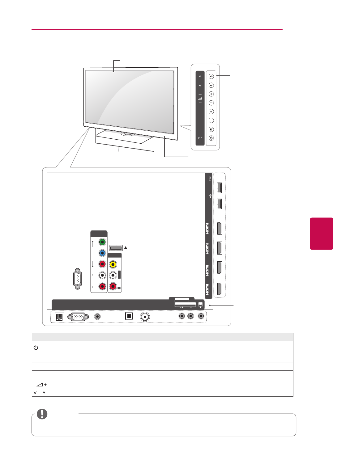
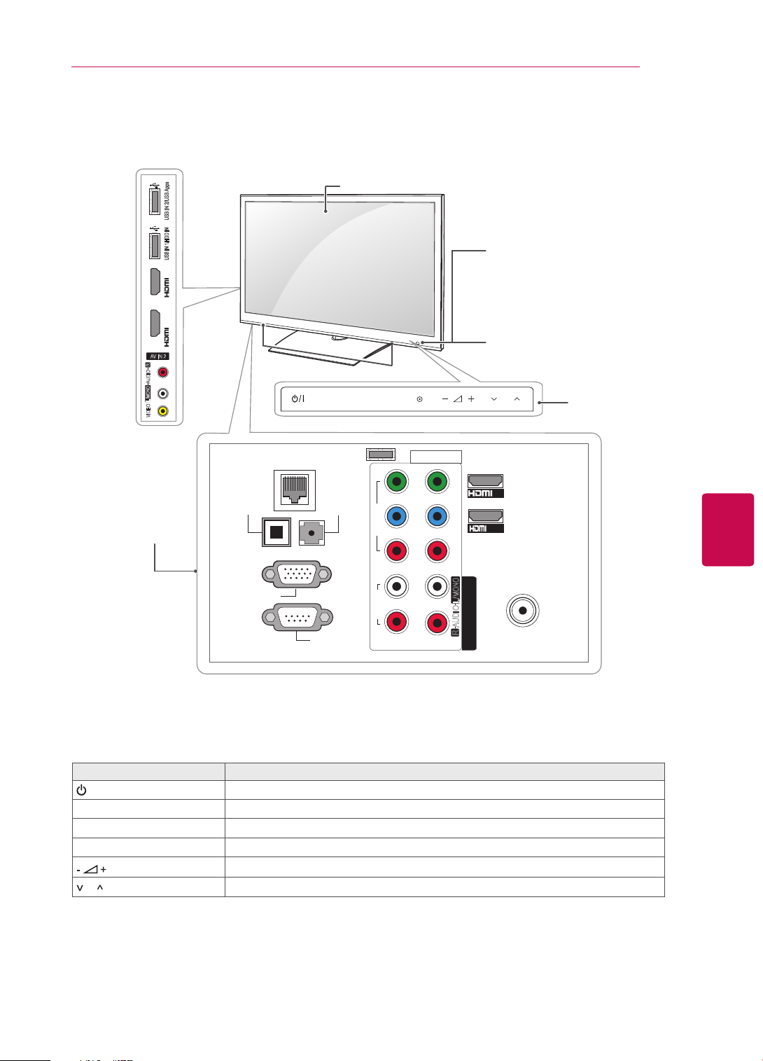
Parts and buttons
Image shown may differ from your TV.
y
NOTE
TV can be placed in standby mode in order to reduce the power consumption. And TV should be
y
turned off if it will not be watched for some time, as this will reduce energy consumption.
The energy consumed during use can be significantly reduced if the level of brightness of the picture
y
is reduced, and this will reduce the overall running cost.
CAUTION
y Do not step on the glass stand or subject it to any impact. It may break, causing possible injury from
fragments of glass, or the TV may fall.
y Do not drag the TV. The floor or the product may be damaged.
y In case of some model, the thin film on screen is a part of TV, so don't take it off.
ENGLISH
ENG
ASSEMBLING AND PREPARING
13
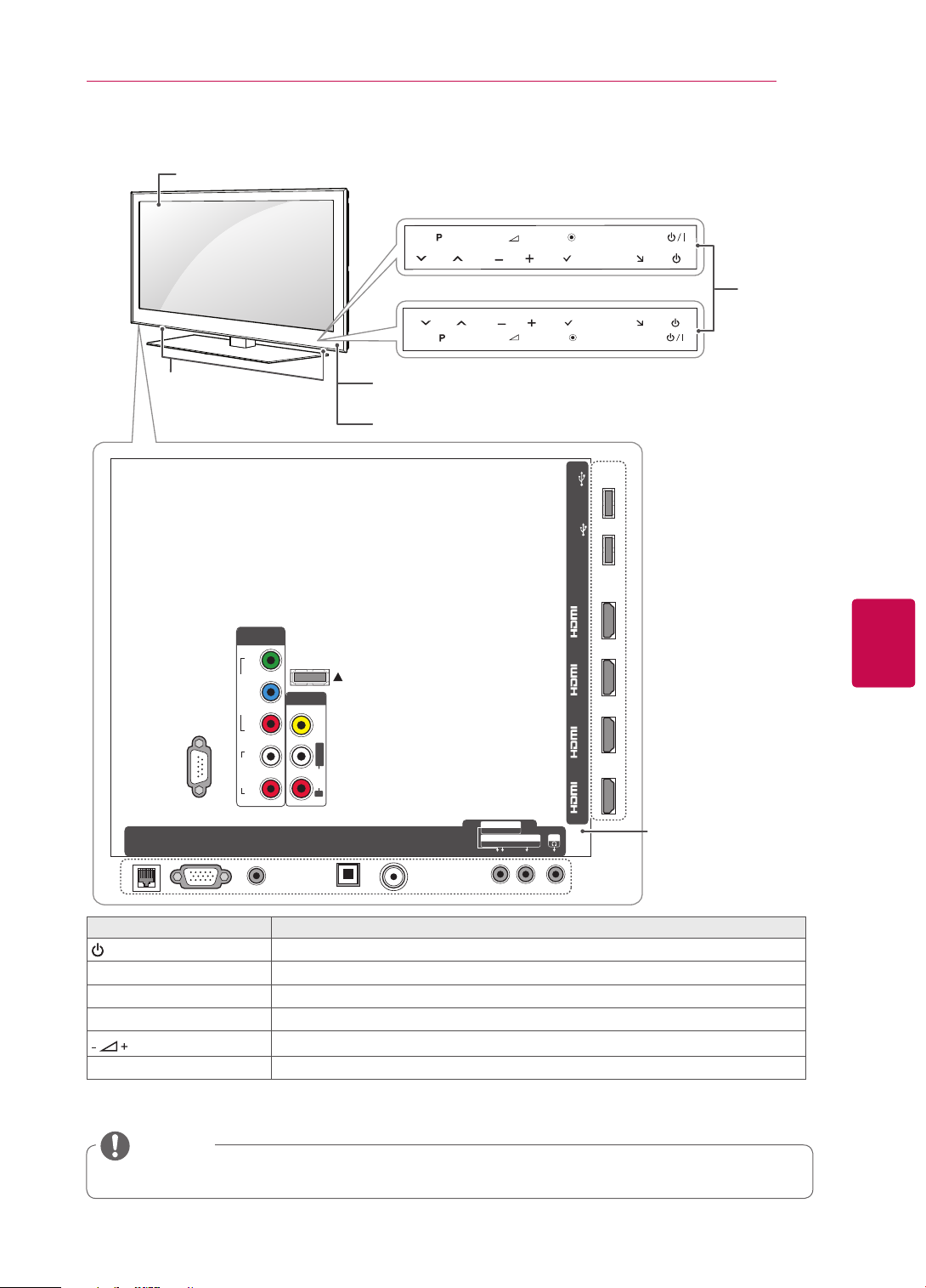
Only 42/47/55/65LW65**, 47/55LW95**, 47/55LW98
Screen
Only 47/55LW95**, 47/55LW98
Only 42/47/55/65LW65
Speakers
Remote control and
intelligent1 sensors
Power indicator
**
**
P
P
OK
**
OK
HOME
H
H
HOME
USB Apps
USB IN 2
HDD IN
USB IN 1
INPUT
INPUT
Touch
buttons
2
COMPONENT
IN 1
Y
WIRELESS
CONTROL
VIDEO
P
B
AV IN 1
VIDEO
L/MONO
AUDIO
R
AUDI O OUT
ANTENNA/
CABLE IN
OPTI CAL DIGI TAL
Turns the power on or off.
AV IN 2
AUDIO / VIDEO
COMPONENT IN 2
AUDIO / Y PB P
Description
/DVI /DVI /DVI /DVI
IN 1(ARC) IN 2 IN 3 IN 4
H/P
R
Rear Connection panel
(See p.119)
LAN
Touch button
/
I
RS-232C IN (CONTROL&SERVICE)
RGB IN (PC)
2
P
R
AUDIO
RL
AUDIO IN
(RGB/DVI)
INPUT Changes the input source.
HOME Accesses the Home menu, or saves your input and exits the menus.
OK
v
P
^
Selects the highlighted menu option or confirms an input.
Adjusts the volume level.
Scrolls through the saved programmes.
1 Intelligent sensor - Adjusts the image quality and brightness based on the surrounding environment.
2 All of the buttons are touch sensitive and can be operated through simple touch with your finger.
ENGENGLISH
NOTE
y You can set the power indicator light to on or off by selecting OPTION in the Home menu - SETUP.
ASSEMBLING AND PREPARING
14
ENGLISH
ENG
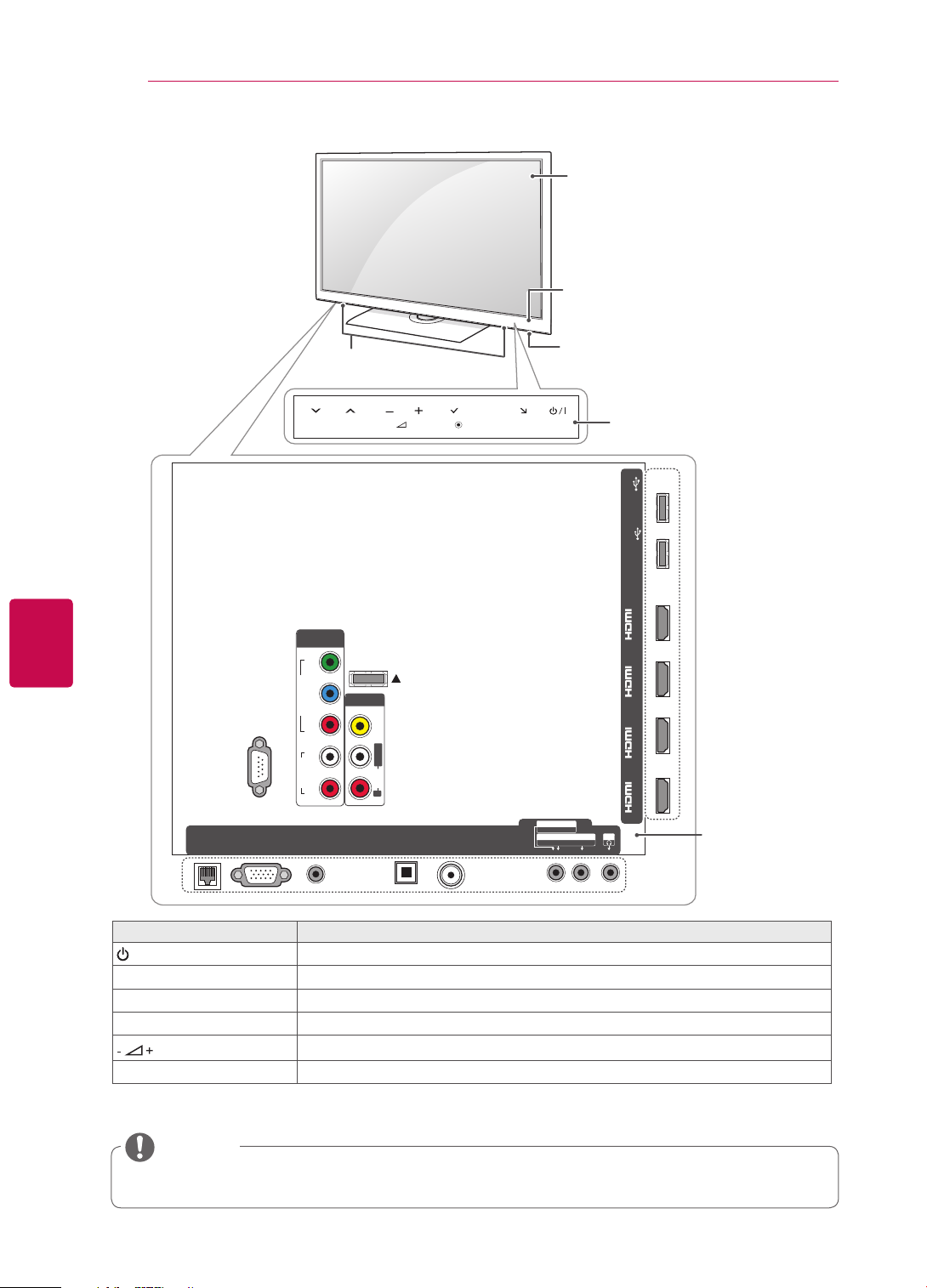
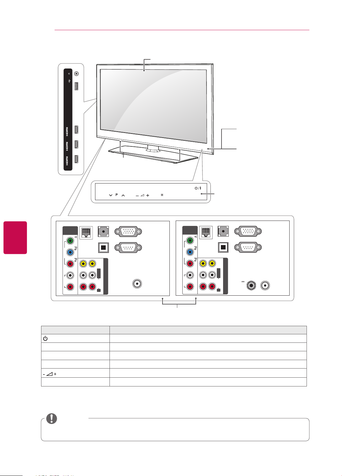
Only 32/37/42/47/55LV55
RS-232C IN (CONTROL&SERVICE)
LAN
RGB IN (PC)
**
Speakers
COMPONENT
IN 1
Y
VIDEO
P
B
P
R
AUDIO
RL
AUDIO IN
(RGB/DVI)
P
WIRELESS
CONTROL
AV IN 1
VIDEO
L/MONO
AUDIO
R
OPTI CAL DIGI TAL
AUDI O OUT
OK
ANTENNA/
CABLE IN
H
HOME
INPUT
Screen
Remote control and
intelligent1 sensors
Power indicator
Touch buttons
USB Apps
USB IN 2
HDD IN
USB IN 1
/DVI /DVI /DVI /DVI
IN 1(ARC) IN 2 IN 3 IN 4
AV IN 2
AUDIO / VIDEO
COMPONENT IN 2
AUDIO / Y PB P
H/P
R
2
Rear Connection
panel
(See p.119)
Touch button
/
I
2
Description
Turns the power on or off.
INPUT Changes the input source.
HOME Accesses the Home menu, or saves your input and exits the menus.
OK
v
P
^
Selects the highlighted menu option or confirms an input.
Adjusts the volume level.
Scrolls through the saved programmes.
1 Intelligent sensor - Adjusts the image quality and brightness based on the surrounding environment.
2 All of the buttons are touch sensitive and can be operated through simple touch with your finger.
NOTE
y You can set the power indicator light to on or off by selecting OPTION in the Home menu - SETUP.
ASSEMBLING AND PREPARING
15
Only 32/42/47/55LW57
RS-232C IN (CONTROL&SERVICE)
LAN
RGB IN (PC)
47/55LW77
**,
COMPONENT
IN 1
Y
VIDEO
P
B
P
R
AUDIO
RL
AUDIO IN
(RGB/DVI)
**
Screen
Speakers
WIRELESS
CONTROL
AV IN 1
VIDEO
L/MONO
AUDIO
R
OPTI CAL DIGI TAL
AUDI O OUT
ANTENNA/
CABLE IN
Buttons
OK
HOME
INPUT
P
H
Remote control and intelligent1
sensors, Power indicator
USB Apps
USB IN 2
HDD IN
USB IN 1
/DVI /DVI /DVI /DVI
IN 1(ARC) IN 2 IN 3 IN 4
AV IN 2
AUDIO / VIDEO
COMPONENT IN 2
AUDIO / Y PB P
H/P
R
Rear Connection panel
(See p.119)
ENGENGLISH
Button Description
/
I
Turns the power on or off.
INPUT Changes the input source.
HOME Accesses the Home menu, or saves your input and exits the menus.
OK
P Scrolls through the saved programmes.
Selects the highlighted menu option or confirms an input.
Adjusts the volume level.
1 Intelligent sensor - Adjusts the image quality and brightness based on the surrounding environment.
NOTE
y You can set the power indicator light to on or off by selecting OPTION in the Home menu - SETUP.
ASSEMBLING AND PREPARING
16
ENGLISH
ENG
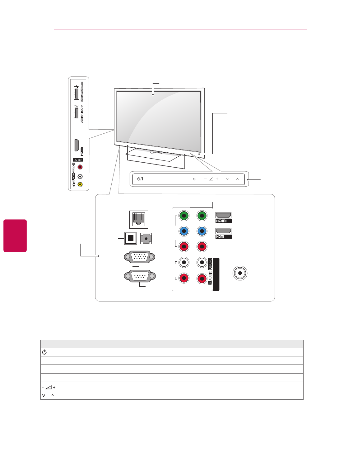
Only 32/37/42/47/55LV37
H/P
USB Apps
USB IN
/DVI
IN 3
/DVI
IN 2
/DVI
IN 1 (ARC)
Except for 32/42/47LV370S
AUDIO IN
COMPONENT
VIDEO
AUDIO
LAN
IN
OPTICAL DIGITAL
AUDIO OUT
VIDEO
L/MONO R
L R
AUDIO
2 1
**
(RGB/DVI)
AV IN
Speakers
P
RGB IN (PC)
RS-232C IN
(CONTROL & SERVICE)
ANTENNA / CABLE IN
Screen
OK
HOME
INPUT
Touch buttons
Only 32/42/47LV370S
AUDIO IN
COMPONENT
VIDEO
AUDIO
LAN
IN
OPTICAL DIGITAL
AUDIO OUT
VIDEO
L/MONO R
L R
AUDIO
2 1
Remote control and
intelligent1 sensors
Power indicator
2
(RGB/DVI)
RGB IN (PC)
RS-232C IN
(CONTROL & SERVICE)
AV IN
13/18V
700mA Max
LNB IN
Satellite
ANTENNA
/ CABLE IN
Rear Connection panel (See p.119)
Touch button
/
I
INPUT Changes the input source.
HOME Accesses the Home menu, or saves your input and exits the menus.
OK
v
P
^
2
Description
Turns the power on or off.
Selects the highlighted menu option or confirms an input.
Adjusts the volume level.
Scrolls through the saved programmes.
1 Intelligent sensor - Adjusts the image quality and brightness based on the surrounding environment.
2 All of the buttons are touch sensitive and can be operated through simple touch with your finger.
NOTE
y You can set the power indicator light to on or off by selecting OPTION in the Home menu - SETUP.
ASSEMBLING AND PREPARING
17
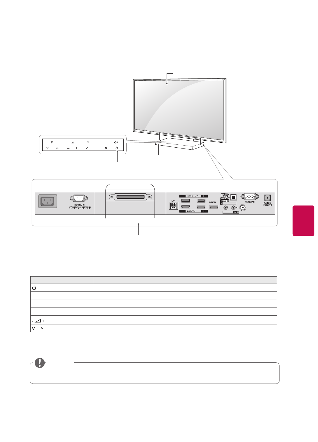
Only 47/55LZ96
P
AC IN
**
HOME
OK
INPUT
H
Power indicator and
Touch buttons
Screen
Speakers
Remote control and
intelligent1 sensors
2
USB IN
/DVI IN
USB Apps
/DVI
Y PB P
R
/ AUDIO
IN3
VIDEO/AUDIO
AV IN
ANTENNA/CABLE IN
ENGENGLISH
HDD IN
DISPLAY LINK
1(ARC)
Rear Connection panel
(See p.119)
Button Description
/
I
Turns the power on or off.
INPUT Changes the input source.
HOME Accesses the Home menu, or saves your input and exits the menus.
OK
P Scrolls through the saved programmes.
Selects the highlighted menu option or confirms an input.
Adjusts the volume level.
1 Intelligent sensor - Adjusts the image quality and brightness based on the surrounding environment.
2 All of the buttons are touch sensitive and can be operated through simple touch with your finger.
NOTE
y You can set the power indicator light to on or off by selecting OPTION in the Home menu - SETUP.
ASSEMBLING AND PREPARING
18
ENGLISH
ENG
Only 50/60PZ57
AV IN 2
R
AUDIO
L/MONO
VIDEO
Rear Connection
panel
(See p.119)
**
USB IN 2/USB Apps
USB IN 1/HDD IN
IN 3(ARC)
OPTICAL
DIGITAL
AUDIO OUT
Speakers
LAN
Screen
INPUT
AUDIO IN
(RGB/DVI)
HOME OK
VIDEO
AV IN 1
Y
B
P
R
P
Remote control and
intelligent1 sensors
Power indicator
P
IN2
VIDEO
/DVI IN1
Touch buttons
2
AUDIO
L
R
1
Description
L/MONO
AUDIO
R
2
ANTENNA IN
COMPONENT IN
Touch button
/
I
RGB IN (PC)
RS-232C IN
(CONTROL & SERVICE)
2
Turns the power on or off.
INPUT Changes the input source.
HOME Accesses the Home menu, or saves your input and exits the menus.
OK
P Scrolls through the saved programmes.
Selects the highlighted menu option or confirms an input.
Adjusts the volume level.
1 Intelligent sensor - Adjusts the image quality and brightness based on the surrounding environment.
2 All of the buttons are touch sensitive and can be operated through simple touch with your finger.
ASSEMBLING AND PREPARING
19
Only 50/60PZ95
AV IN 2
R
AUDIO
L/MONO
VIDEO
Rear Connection
panel
(See p.119)
**
USB IN 2/USB Apps
USB IN 1/HDD IN
IN 4
IN 3(ARC)
OPTICAL
DIGITAL
AUDIO OUT
Speakers
LAN
Screen
INPUT
WIRELESS
CONTROL
AUDIO IN
(RGB/DVI)
HOME OK
VIDEO
AV IN 1
Y
B
P
R
P
Remote control and
intelligent1 sensors
Power indicator
P
IN2
VIDEO
/DVI IN1
Touch buttons
2
ENGENGLISH
AUDIO
L
R
1
Description
L/MONO
AUDIO
R
2
ANTENNA IN
COMPONENT IN
Touch button
/
I
RGB IN (PC)
RS-232C IN
(CONTROL & SERVICE)
2
Turns the power on or off.
INPUT Changes the input source.
HOME Accesses the Home menu, or saves your input and exits the menus.
OK
P Scrolls through the saved programmes.
Selects the highlighted menu option or confirms an input.
Adjusts the volume level.
1 Intelligent sensor - Adjusts the image quality and brightness based on the surrounding environment.
2 All of the buttons are touch sensitive and can be operated through simple touch with your finger.
ENGLISH
ENG
ASSEMBLING AND PREPARING
20
Lifting and moving the TV
When moving or lifting the TV, read the following to
prevent the TV from being scratched or damaged
and for safe transportation regardless of its type
and size.
CAUTION
Avoid touching the screen at all times, as this
y
may result in damage on the screen.
It is recommended to move the TV in the box
y
or packing material that the TV originally came
in.
Before moving or lifting the TV, disconnect the
y
power cord and all cables.
When holding the TV, the screen should face
y
away from you to avoid damage.
Hold the top and bottom of the TV frame firmly.
y
Make sure not to hold the transparent part,
speaker, or speaker grill area.
Setting up the TV
Put your TV on a pedestal stand and mount the TV
on a table or wall.
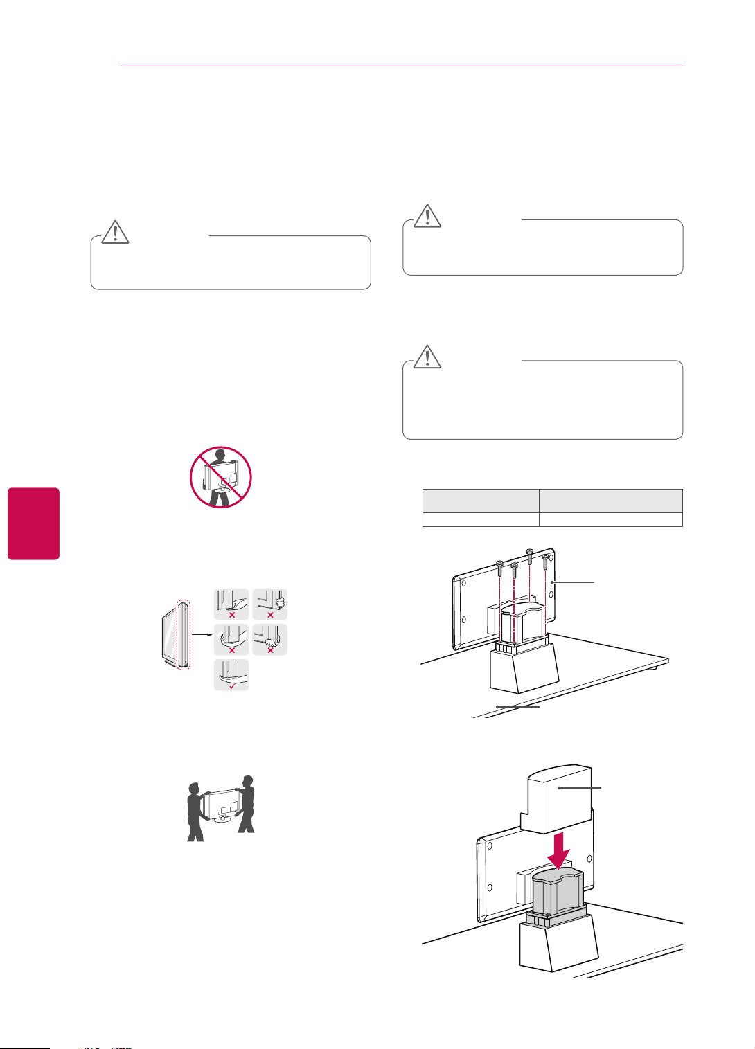
Attaching the stand
If you are not mounting the TV to a wall, use the
following instructions to attach the stand.
CAUTION
y Tighten the screws firmly to prevent the TV
from tilting forward. Do not over tighten.
Only 47/55LW95**, 47/55LW98
Lay the TV with the screen side down on a flat
1
surface.
CAUTION
Lay a foam mat or soft protective cloth on the
y
surface to protect the screen from damage.
Make sure no objects press against the
screen.
Assemble the parts of the Stand Body with the
2
Stand Base of the TV.
Screw for assembly Number of screws
M4 x 16 4
**
Stand Body
When transporting a large TV, there should be
y
at least 2 people.
When transporting the TV by hand, hold the
y
TV as shown in the following illustration.
When transporting the TV, do not expose the
y
TV to jolts or excessive vibration.
When transporting the TV, keep the TV
y
upright, never turn the TV on its side or tilt
towards the left or right.
Stand Base
Assemble the parts of the Stand Rear Cover
3
with the TV.
Stand Rear
Cover
ASSEMBLING AND PREPARING
21
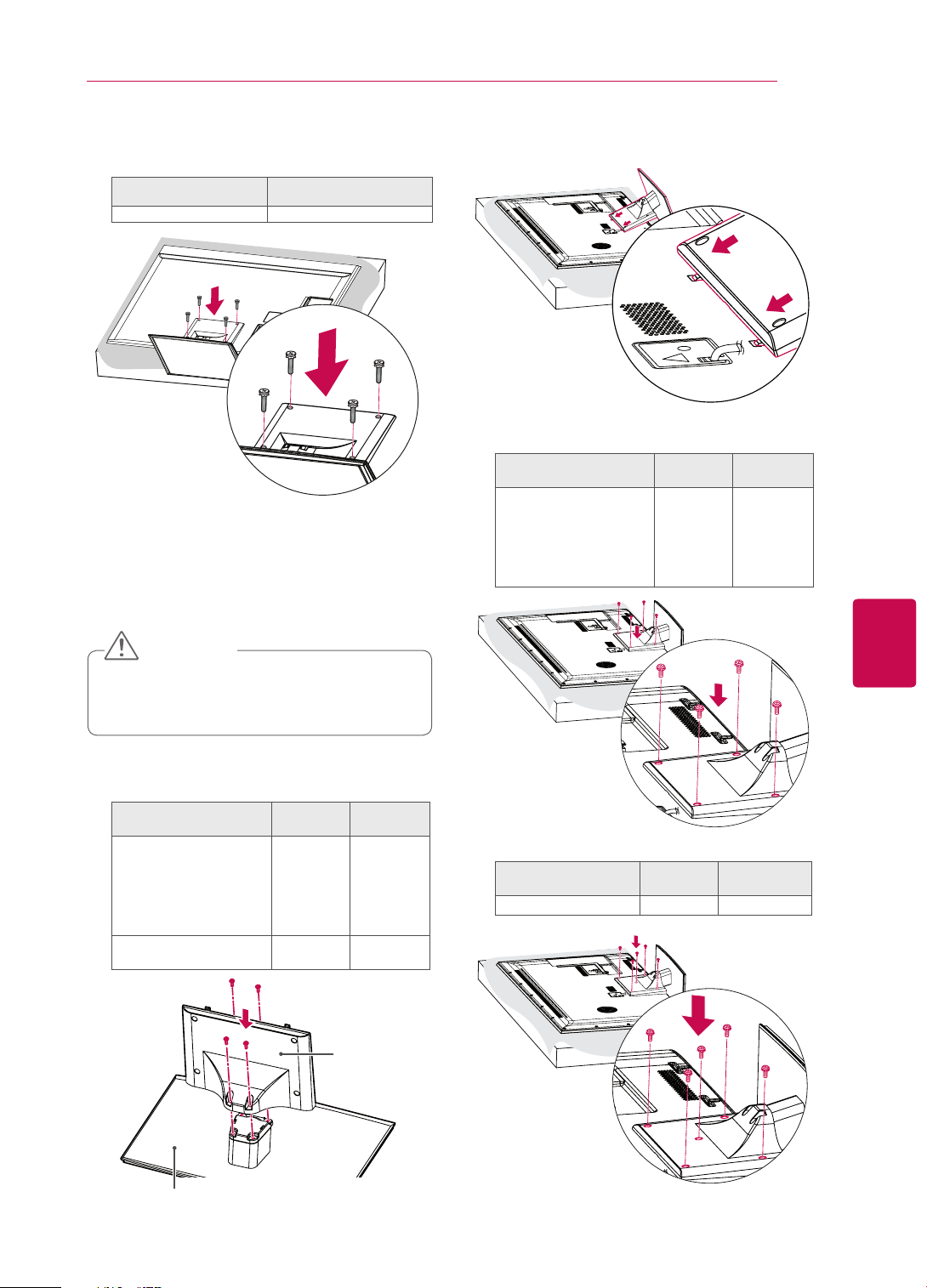
4 Secure the TV and the stand with the 4 screws.
Screw for assembly Number of screws
M4 x 16 4
Only 32/37/42/47/55LV37**,
32/37/42/47/55LV55**, 32/42/47/55LW57**,
42/47/55/65LW65
Lay the TV with the screen side down on a flat
1
surface.
47/55LW77
**,
**
Assemble the TV as shown.
3
4 Secure the TV and the stand with the 4 screws.
Model Screw for
32/37/42/47/55LV37**,
assembly
M4 x 12 4
32/37/42/47/55LV55**,
32/42/47/55LW57**,
42/47/55LW65
47/55LW77
**,
**
Number of
screws
ENGENGLISH
CAUTION
Lay a foam mat or soft protective cloth on the
y
surface to protect the screen from damage.
Make sure no objects press against the
screen.
Assemble the parts of the Stand Body with the
2
Stand Base of the TV.
Model Screw for
32/37/42/47/55LV37**,
assembly
M4 x 12 4
32/37/42/47/55LV55**,
32/42/47/55LW57**,
42/47/55LW65
47/55LW77
65LW65
**,
**
**
M4 x 16 4
Number of
screws
Stand Body
Model Screw for
65LW65
**
assembly
M4 x 16 5
Number of
screws
Stand Base
ASSEMBLING AND PREPARING
22
ENGLISH
ENG
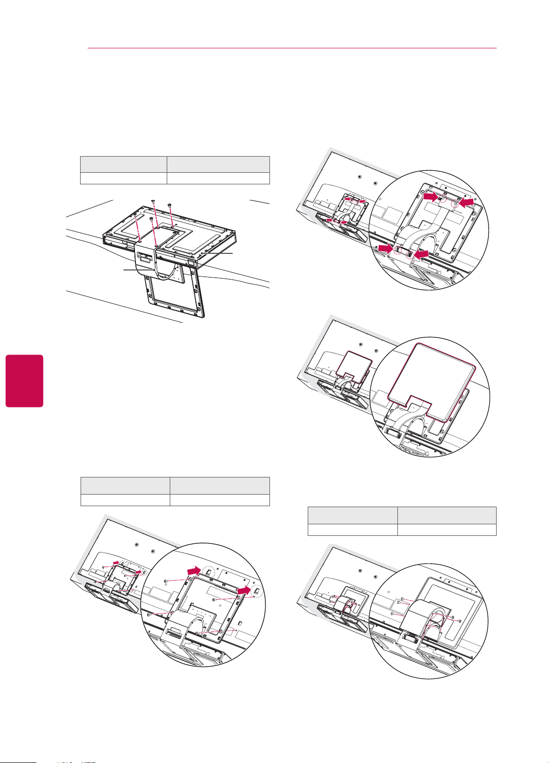
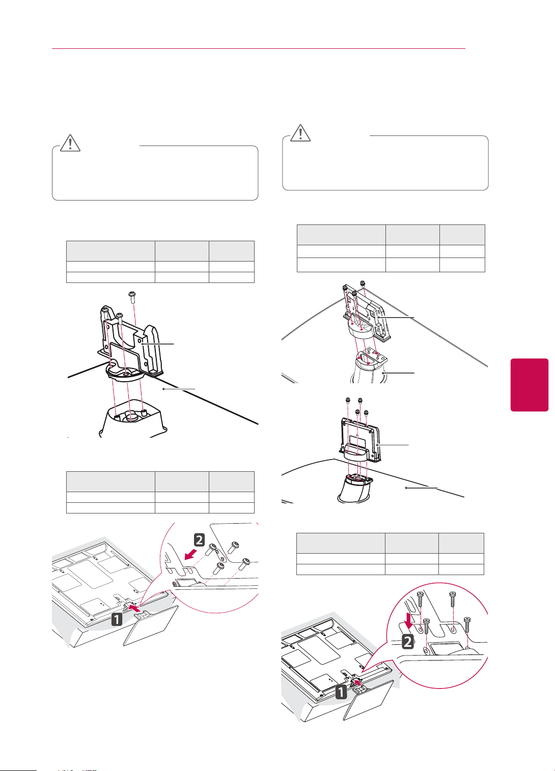
Only 47/55LZ96**
Place the stand base facing down on a table
1
or flat surface. Assemble the Stand Body with
the Stand Base using the screws provided
with the TV set.
Screw for assembly Number of screws
M4 x 7 4
Stand
Stand Body
Carefully place the TV screen side down on a
2
cushioned surface to protect the screen from
damage.
Base
Use the Display Link Cable (for stand; the
4
shorter one) to connect the Stand Base and
the display link input on the TV. After connection, fasten the screws with a driver to mount
the cable tightly.
Place the Stand Rear Cover properly.
5
Mount the stand to the TV set fitting into
3
grooves in direction of the arrows as shown in
the figure. Have the TV set align with the holes
for inserting screws. Assemble the Stand Body
with the TV set using the screws provided with
the TV set.
Screw for assembly Number of screws
M4 x 14 4
Place the Display Link Cable Cover and con-
6
nect it with the Stand Body using the screws
provided with the TV set.
Screw for assembly Number of screws
M3 x 6 4
ASSEMBLING AND PREPARING
23
Only 50/60PZ57
Lay the TV with the screen side down on a flat
1
**
surface.
CAUTION
Lay a foam mat or soft protective cloth
y
on the surface to protect the screen from
damage. Make sure no objects press
against the screen.
Assemble the parts of the Stand Body with the
2
Stand Base of the TV.
Model Screw for
50PZ57
60PZ57
**
**
assembly
M5 x 14.5 3
M5 x 24 3
Stand Body
Number of
screws
Only 50/60PZ95
Lay the TV with the screen side down on a flat
1
**
surface.
CAUTION
Lay a foam mat or soft protective cloth
y
on the surface to protect the screen from
damage. Make sure no objects press
against the screen.
Assemble the parts of the Stand Body with the
2
Stand Base of the TV.
Model Screw for
50PZ95
60PZ95
**
**
assembly
M5x14.5 3
M5x14.5 4
Number of
screws
Stand Body
Stand Base
ENGENGLISH
Stand Base
3 Secure the TV and the stand with the 4 screws.
Model Screw for
50PZ57
60PZ57
**
**
assembly
M4 x 26 4
M4 x 28 4
Number of
screws
or
Stand Body
Stand Base
3 Secure the TV and the stand with the 4 screws.
Model Screw for
50PZ95
60PZ95
**
**
assembly
M4 x 26 4
M4 x 28 4
Number of
screws
ASSEMBLING AND PREPARING
24
ENGLISH
ENG
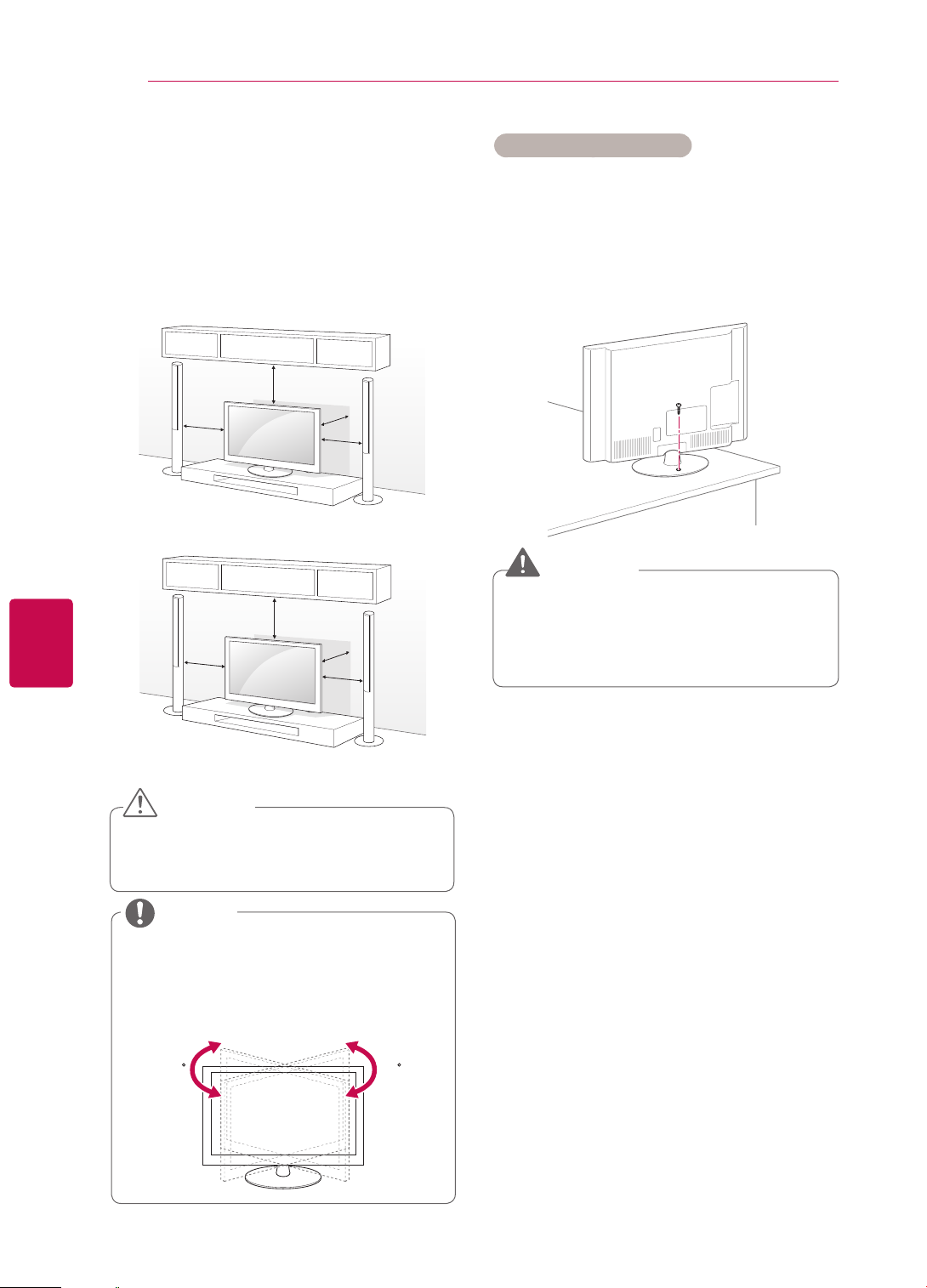
Mounting on a table
Lift and tilt the TV into its upright position on a
1
table.
- Leave a 10 cm (minimum) space from the
wall for proper ventilation.
Except for 47/55LZ96
10 cm
Only 47/55LZ96
10 cm
**
10 cm
10 cm
10 cm
**
10 cm
21 cm
10 cm
Securing the TV to a table
(Only 32/37LV55**, 32/37LV37**, 32LW57**)
Fix the TV to a table to prevent from tilting forward,
damage, and potential injury.
Mount the TV on a table, and then insert and
tighten the supplied screw on the rear of the stand.
WARNING
y To prevent TV from falling over, the TV
should be securely attached to the floor/wall
per installation instructions. Tipping, shaking,
or rocking the TV may cause injury.
Connect the power cord to a wall outlet.
2
CAUTION
y Do not place the TV near or on sources of
heat, as this may result in fire or other dam-
age.
NOTE
Except for 47/55LZ96
y Swivel 20 degrees to the left or right and
adjust the angle of the TV to suit your
view.
**
2020
ASSEMBLING AND PREPARING
25
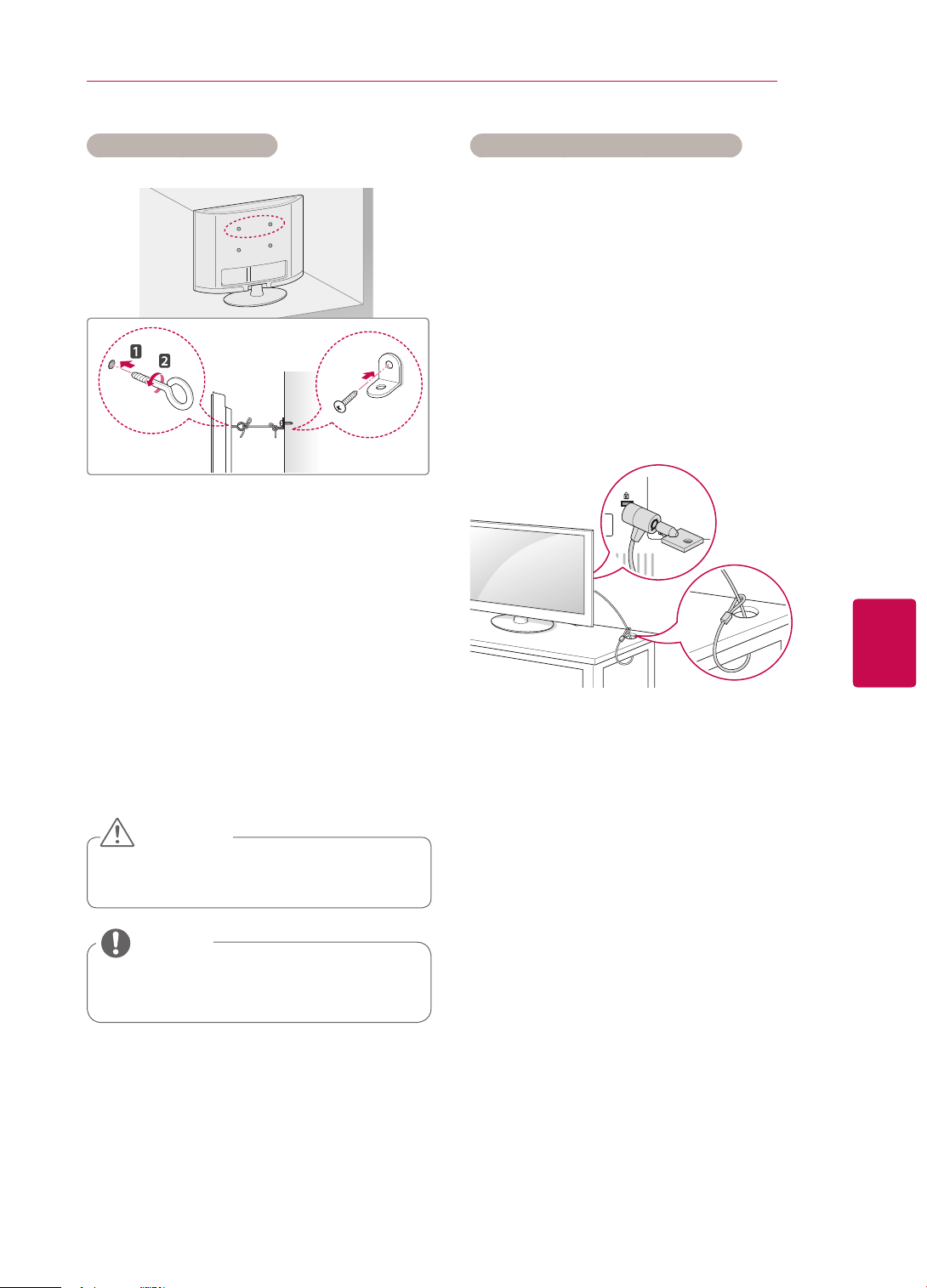
Securing the TV to a wall
(This feature is not available for all models.)
Insert and tighten the eye-bolts, or TV brackets
1
and bolts on the back of the TV.
- If there are bolts inserted at the eye-bolts
position, remove the bolts first.
Mount the wall brackets with the bolts to the
2
wall.
Using the Kensington security system
(This feature is not available for all models.)
The Kensington security system connector is located at the rear of the TV. For more information of
installation and using, refer to the manual provided
with the Kensington security system or visit http://
www.kensington.com.
Connect the Kensington security system cable
between the TV and a table.
ENGENGLISH
Match the location of the wall bracket and the
eye-bolts on the rear of the TV.
Connect the eye-bolts and wall brackets tightly
3
with a sturdy rope.
Make sure to keep the rope horizontal with the
flat surface.
CAUTION
y Make sure that children do not climb on or
hang on the TV.
NOTE
y Use a platform or cabinet that is strong and
large enough to support the TV securely.
ASSEMBLING AND PREPARING
26
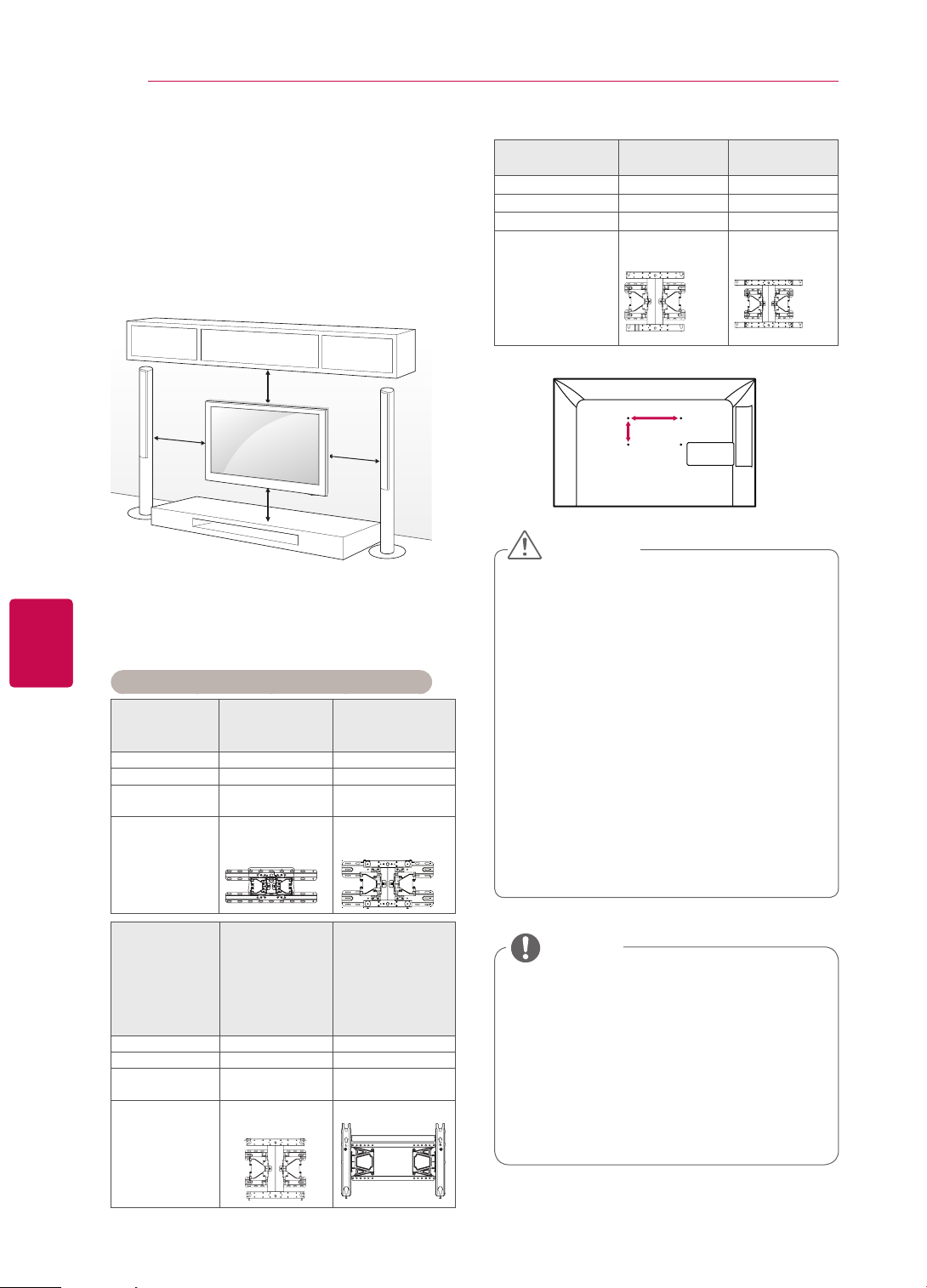
Mounting on a wall
ENGLISH
ENG
Attach a wall mount bracket at the rear of the TV
carefully and install the wall mount bracket on a
solid wall perpendicular to the floor. When you
attach the TV to other building materials, please
contact qualified personnel.
LG recommends that wall mounting be performed
by a qualified professional installer.
10 cm
10 cm
10 cm
10 cm
Make sure to use screws and wall mount bracket
that meet the VESA standard. Standard dimensions for the wall mount kits are described in the
following table.
Separate purchase(Wall Mounting Bracket)
Model 32LV37**,
VESA (A x B) 200 x 100 200 x 200
Standard screw M4 M6
Number of
screws
Wall mount
bracket
32LV55**,
32LW57
**
4 4
LSW100B,
LSW100BG
37LV55**,
37LV37
**
LSW200B,
LSW200BG
Model
VESA (A x B) 400 x 400 600 x 400
Standard screw M6 M8
Number of screws 4 4
Wall mount
bracket
50PZ57
**
50PZ95
**
PSW400B,
PSW400BG
60PZ57
**
60PZ95
**
PSW600B,
PSW600BG
A
B
CAUTION
y Disconnect the power first, and then move or
install the TV. Otherwise electric shock may
occur.
y If you install the TV on a ceiling or slanted
wall, it may fall and result in severe injury.
Use an authorized LG wall mount bracket
and contact the local dealer or qualified
personnel.
y Do not over tighten the screws as this may
cause damage to the TV and void your warranty.
y Use the screws and wall mount bracket that
meet the VESA standard. Any damages or
injuries by misuse or using an improper accessory are not covered by the warranty.
Model
VESA (A x B) 400 x 400 600 x 400
Standard screw M6 M8
Number of
screws
Wall mount
bracket
42/47/55LV37**,
42/47/55LV55**,
42/47/55LW65**,
42/47/55LW57**,
47/55LW77**,
47/55LW95**,
47/55LW98**,
47/55LZ96
4 4
LSW400B,
LSW400BG
**
65LW65
LSW600B,
**
NOTE
y Use the screws that are listed on the VESA
standard screw specifications.
y The wall mount kit includes an installation
manual and necessary parts.
y The length of screws may differ depending
on the wall mount. Make sure to use the
proper length.
y For more information, refer to the manual
supplied with the wall mount bracket.
ASSEMBLING AND PREPARING
27
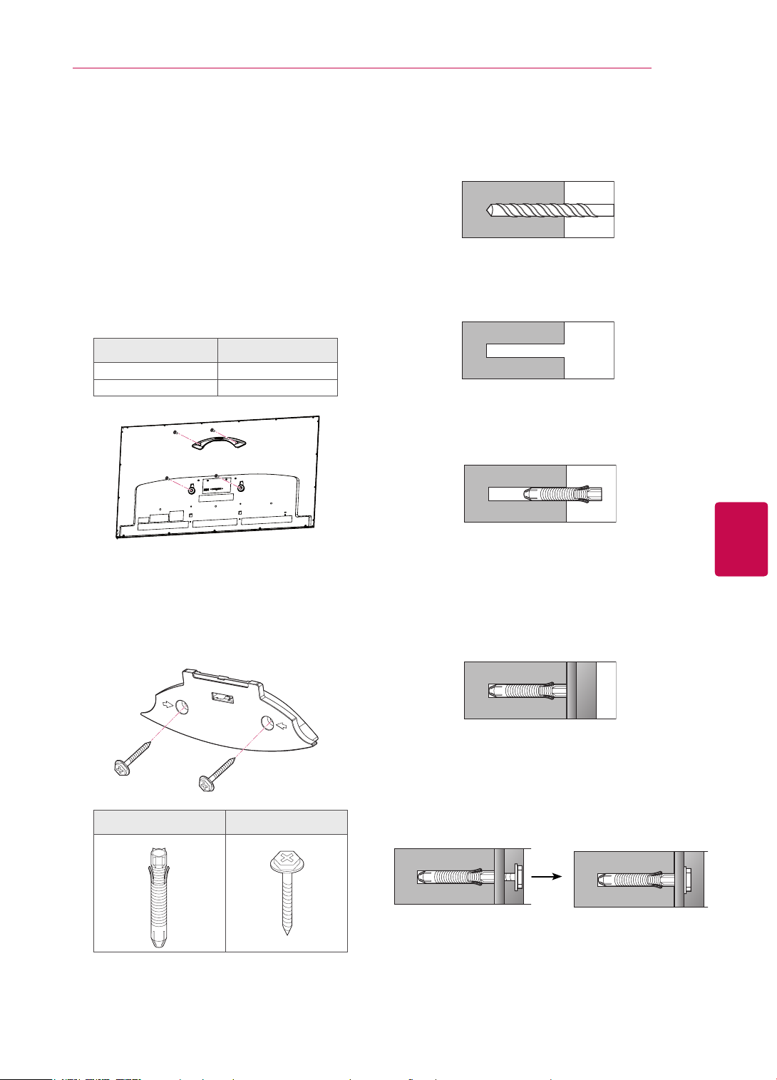
Wall mounting bracket installation
Only 47/55LZ96
Carefully place the TV screen side down on a
1
cushioned surface to protect the screen from
damage.
Fasten the screws to mount the Wall Mount-
2
ing Bracket for the set and the Set Protection
Brackets to the TV set.
Screw for assembly Number of screws
M4 x 7 2
M4 x 14 2
**
3-1Drill holes with depth of 80 mm - 100 mm at
the anchor location with a 8 mm drill bit.
3-2Clean the drilled holes.
3-3Insert the Wall Anchor provided in the hole.
ENGENGLISH
Mount the Wall Mounting Bracket to the place
3
you want using the Wall Anchors and Screws
as shown below. You can adjust the level of the
Wall Mounting Bracket with the level gauge
attached.
Wall Anchor Screw
3-4Push the Wall Mounting Bracket to the wall
aligning with the hole. Make sure that the angle
adjusting knob is located on the upper side of
the Wall Mounting Bracket.
3-5Screw the Screw for the Wall Mounting
Bracket into the hole. At this time, fasten the
Screw applying a torque of at least 45 kgf•cm.
ASSEMBLING AND PREPARING
28
ENGLISH
ENG
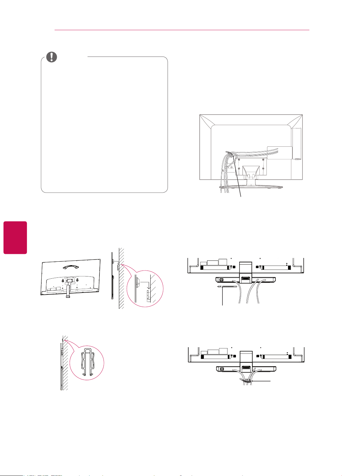
NOTE
y Check the material of the wall and thickness
of finishing material.
y You can use the anchors and screws pro-
vided with the TV set for the wall made with
concrete, lightweight concrete, soft fieldstone, hard fieldstone, brick or cellular block.
y Do not mount on the wall made with plaster
board or medium density fibreboard (MDF).
In this case, the anchor and screws must be
inserted in the concrete inside of finishing
material. If there is no concrete inside, you
must install a separate hanger first and fix
the anchors and screws.
y For other cases, make sure that each fixed
part can resist the pull-out load of 70 kgf
(686 N) and shear load of 100 kgf.
4 Connect the Display Link Cable (for wall
mounting bracket; the longer one) to the
display link input on the back of the TV. Then,
mount the TV set on the wall in direction of the
arrow as shown in the figure.
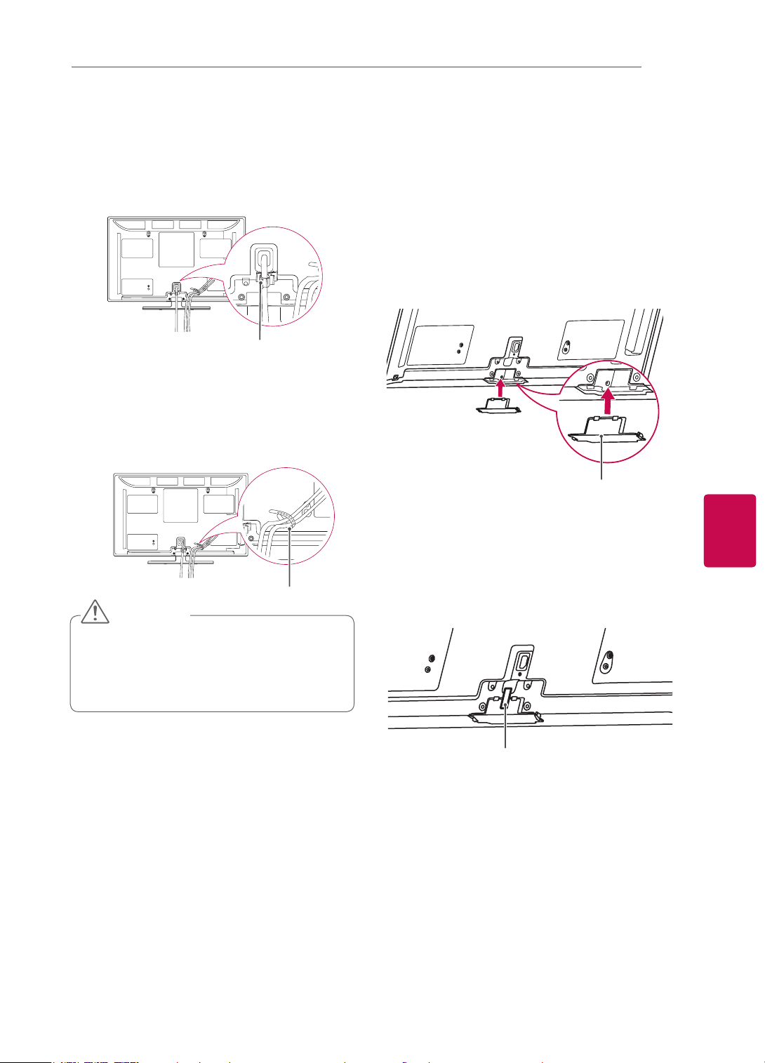
Tidying cables
Only 32/37/42/47/55LV37
32/42/47/55LW57**, 42/47/55/65LW65**,
47/55LW77
47/55LW95**, 47/55LW98
**,
1 Gather and bind the cables with the Cable
Holder on the TV back cover.
Cable Holder
Only 47/55LZ96**
1 Secure the power cord with the Cable Holder
on the TV back cover. It will help prevent the
power cable from being removed by accident.
32/37/42/47/55LV55**,
**,
**
5 Secure the set with the Wall Mounting
Bracket Pushpins.
Wall Mounting
Bracket Pushpin
6 Place the Stand Base in a proper location and
connect it with the Display Link Cable.
Cable Holder
2 After connecting the cables as necessary,
install Cable Holder as shown and bundle the
cables.
Cable Holder
ASSEMBLING AND PREPARING
29
Only 50/60PZ57**, 50/60PZ95
**
1 Install the Power Cord Holder and Power
Cord. It will help prevent the power cable from
being removed by accident.
Power Cord Holder
2 Gather and bind the cables with the Cable
Holder. Install the LAN cable as shown to
reduce the electromagnetic wave.
Not using the Desk-Type Stand
Only 50/60PZ57**, 50/60PZ95
When installing the wall mounting bracket,
y
use the Protection cover. This will protect the
opening from accumulating dust and dirt.
Push the supplied protection cover into the
1
opening at the bottom of the TV until it locks in
place.
**
Protection cover
ENGENGLISH
Cable Holder
CAUTION
y Do not move the TV by holding the Cable
Holder & Power Cord Holder, as the Cable
holders may break, and injuries and damage
to the TV may occur.
Attach the protection tape as shown in the
2
figure below to keep the protection cover
secure while moving the TV set.
Protection tape
ENGLISH
AV MODE INPUT
TV/
RAD
ENERGY
SAVING
LIGHT
아시아, 이스라엘/남아공/이란 제외 호주/뉴질, 아시아, 이스라엘/남아공/이란
AV MODE INPUT
TV/
RAD
ENERGY
LIST
Q.VIEW
MARK
SAVING
1 2
ABC3 DEF
4
GHI5 JKL6
MNO
7
PQRS8 TUV
0
9
WXYZ
LIGHT
AV MODE INPUT
TV/
RAD
ENERGY
SAVING
AV MODE INPUT
TV/
RAD
ENERGY
LIST
Q.VIEW
SAVING
1 2
ABC3 DEF
4
GHI5 JKL6
MNO
7
PQRS8 TUV
0
9
WXYZ
LZ9600/LW9500/LW7700/LW6500/LW5700 LV5500/LV3700/LV370S
AV MODE INPUT
TV/
RAD
ENERGY
SAVING
LZ9600/LW9500/LW7700/LW6500/LW5700 LV5500/LV3700/LV370S
ENG
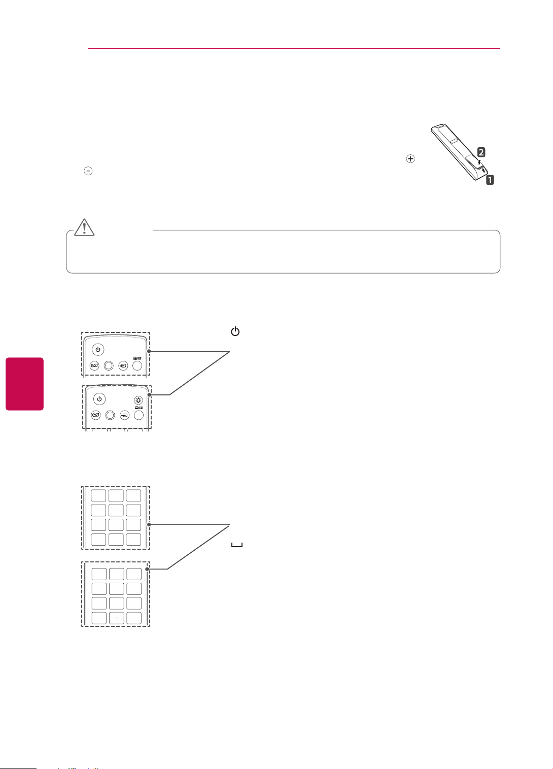
REMOTE CONTROL
30
REMOTE CONTROL
The descriptions in this manual are based on the buttons on the remote control.
Please read this manual carefully and use the TV correctly.
To replace batteries, open the battery cover, replace batteries (1.5 V AAA) matching
and ends to the label inside the compartment, and close the battery cover. Be sure to
point the remote control toward the remote control sensor on the TV.
To remove the batteries, perform the installation actions in reverse.
CAUTION
Do not mix old and new batteries, as this may damage the remote control.
y
In Analogue TV and in some countries, some remote control keys may not work.
y
(POWER)
Turns the TV on or off.
ENERGY
SAVING
ENERGY
SAVING
AV MODE INPUT
AV MODE INPUT
TV/
RAD
LIGHT
TV/
RAD
LIGHT
Illuminates the remote control buttons.
ENERGY SAVING (See p.101)
Adjusts the brightness of the screen to reduce energy consumption.
AV MODE (See p.43)
Selects an AV mode.
INPUT (See p.44)
Changes the input source; Turns the TV on.
TV/RAD
Selects Radio, TV and DTV programme.
1 2
ABC3 DEF
4
GHI5 JKL6
7
PQRS8 TUV
LIST
0
MNO
WXYZ
9
Q.VIEW
Alphanumeric buttons
Enters letters and numbers.
LIST (See p.40)
Accesses the saved programme list.
(Space)
Opens an empty space on the screen keyboard.
Q.VIEW
1 2
ABC3 DEF
4
GHI5 JKL6
7
PQRS8 TUV
LIST
MNO
WXYZ
9
Q.VIEW
0
Returns to the previously viewed programme.
 Loading...