

LG 50PG70FD User manual [pt]

P/NO : MFL41469203 (0807-REV03)
Please read this manual carefully before operating your set
and retain it for future reference.
Write the model number and serial number from the label
on the back cabinet on the front or back of this manual.
42LB7DF
47LB7DF
32LG50D
37 LG 50 D
42LG50D
47LG 50 D
52LG50FD
42LG70YD
47LG70YD
52LG70YD
32LG80FD
42LG80FD
42PG60D
50PG60D
50PG70FD
60PG70FD
42PG30D
50PG30D
PLASMA TV
LCD TV
OWNER’S MANUAL
serviço de atendimento
ao consumidor
4004 5400 Capitais e Regiões Metropolitanas
0800 707 5454 Demais localidades
EM CASO DE DÚVIDA, CONSULTE NOSSO SAC
WWW.LGE.COM.BR
SAC

1
SAFETY INSTRUCTIONS
IMPORTANT SAFETY INSTRUCTIONS
Important safety instructions shall be provided with each apparatus. This information shall be given in a
separate booklet or sheet, or be located before any operating instructions in an instruction for installation
for use and supplied with the apparatus.
This information shall be given in a language acceptable to the country where the apparatus is intended to
be used.
The important safety instructions shall be entitled “Important Safety Instructions”. The following safety
instructions shall be included where applicable, and, when used, shall be verbatim as follows. Additional
safety information may be included by adding statements after the end of the following safety instruction
list. At the manufacturer’s option, a picture or drawing that illustrates the intent of a specific safety instruction
may be placed immediately adjacent to that safety instruction :
Read these instructions.
Keep these instructions.
Heed all warnings.
Follow all instructions.
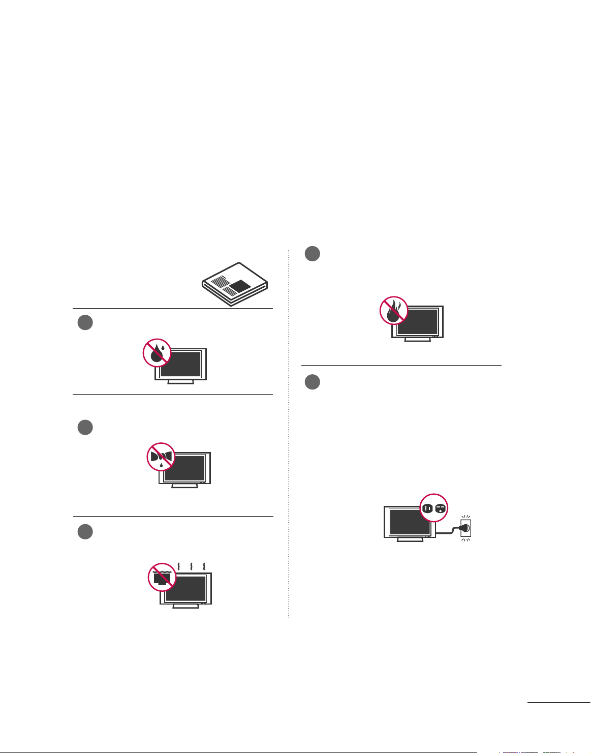
Do not use this apparatus near water.
Clean only with dry cloth.
Do not block any ventilation openings. Install in
accordance with the manufacturer’s instructions.
Do not install near any heat sources such as
radiators, heat registers, stoves, or other apparatus
(including amplifiers)that produce heat.
Do not defeat the safety purpose of the
polarized or grounding-type plug. A polarized
plug has two blades with one wider than the
other. A grounding type plug has two blades
and a third grounding prong, The wide blade
or the third prong are provided for your safety.
If the provided plug does not fit into your
outlet, consult an electrician for replacement
of the obsolete outlet.
1
4
5
2
3
2
SAFETY INSTRUCTIONS
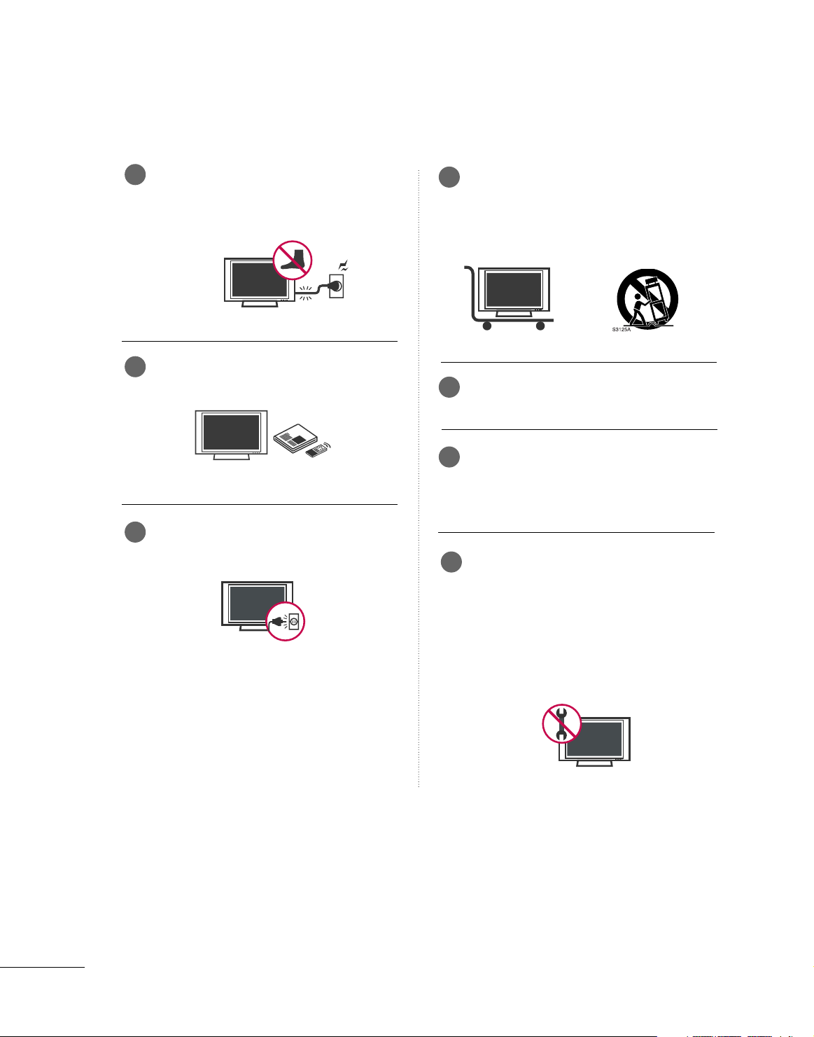
Protect the power cord from being walked on
or pinched particularly at plugs, convenience
receptacles, and the point where they exit
from the apparatus.
Only use attachments/accessories specified
by the manufacturer.
Unplug this apparatus when unused for long
periods of time.
Use only with the cart, stand, tripod, bracket,
or table specified by the manufacturer, or sold
with the apparatus. When a cart is used, use
caution when moving the cart/apparatus
combination to avoid injury from tip-over.
Never touch this apparatus or antenna during
a thunder or lighting storm.
Do not allow a impact shock or any objects to
fall into the product, and do not drop onto the
screen with something. (You may be injured or
the product can be damaged.)
Refer all servicing to qualified service personnel.
Servicing is required when the apparatus has
been damaged in any way, such as power-supply
cord or plug is damaged, liquid has been
spilled or objects have fallen into the apparatus,
the apparatus has exposed to rain or moisture,
does not operate normally, or has been
dropped.
6
7
8
9
10
11
12
3
CAUTION concerning the Power Cord :
Most appliances recommend they be placed
upon a dedicated circuit; that is, a single outlet
circuit which powers only that appliance and
has no additional outlets or branch circuits.
Check the specification page of this owner's
manual to be certain.
Do not overload wall outlets. Overloaded wall
outlets, loose or damaged wall outlets, extension
cords, frayed power cords, or damaged or
cracked wire insulation are dangerous. Any of
these conditions could result in electric shock
or fire. Periodically examine the cord of your
appliance, and if its appearance indicates
damage or deterioration, unplug it, discontinue
use of the appliance, and have the cord
replaced with an exact replacement part by
an authorized servicer. Protect the power cord
from physical or mechanical abuse, such as
being twisted, kinked, pinched, closed in a
door, or walked upon. Pay particular attention
to plugs, wall outlets, and the point where
the cord exits the appliance.
Outdoor Use Marking :
WARNING - To Reduce The Risk Of Fire Or
Electric Shock, Do Not Expose This Appliance
To Rain Or Moisture
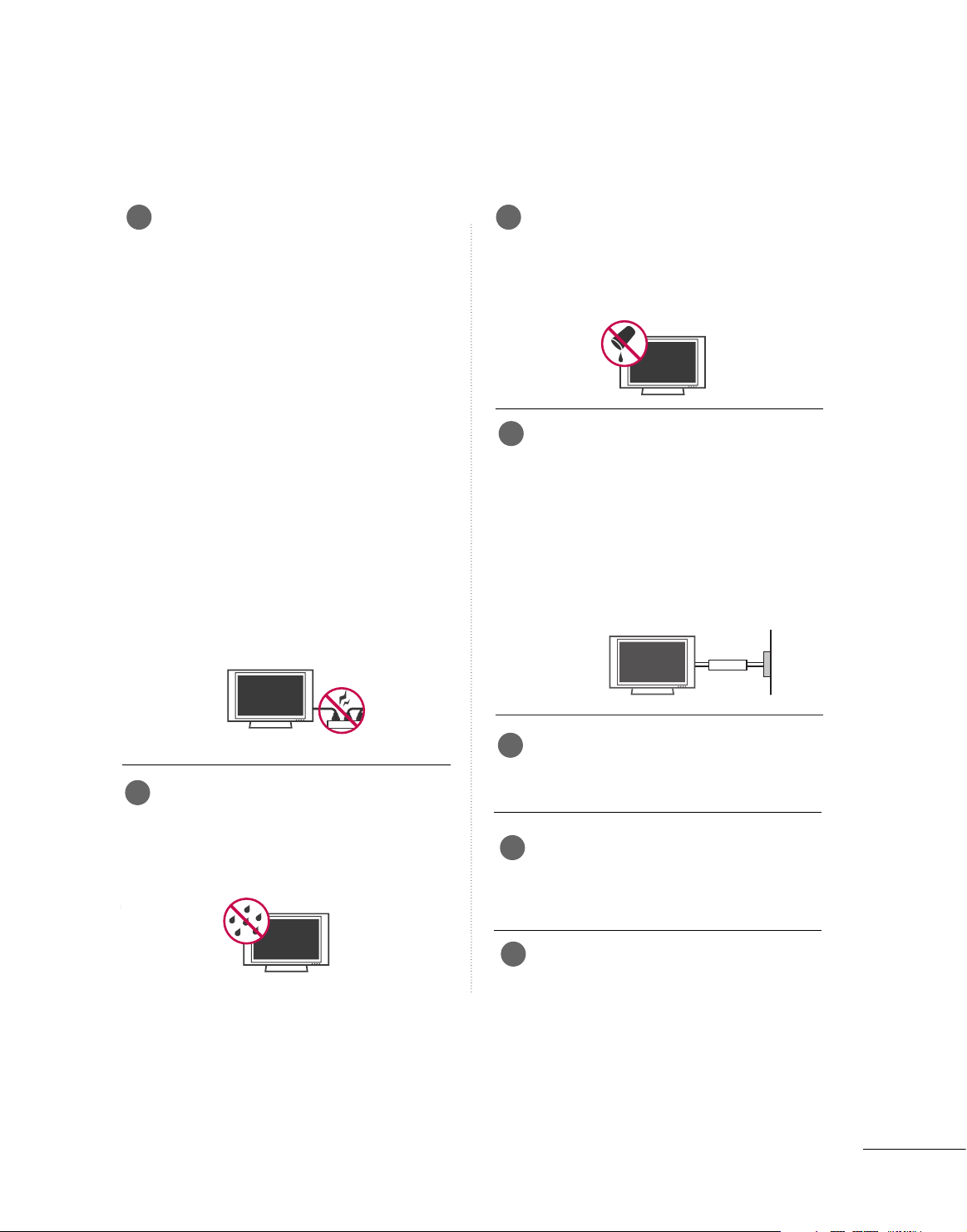
Wet Location Marking : Apparatus shall not
be exposed to dripping or splashing and no
objects filled with liquids, such as vases, shall
be placed on or over apparatus.
GROUNDING
Ensure that you connect the earth ground
wire to prevent possible electric shock. If
grounding methods are not possible, have a
qualified electrician install a separate circuit
breaker.
Do not try to ground the unit by connecting
it to telephone wires, lightening rods, or gas
pipes.
DISCONNECTING DEVICE FROM MAINS
Main plug is the disconnecting device. The
plug must remain readily operable.
When mounting a TV it on the wall, make
sure not to install TV by hanging power and
signal cables on the back of the TV.
- It may cause fire, electric shock.
Keep the product away from direct sunlight.
- The product can be damaged.
Owner Manual
Power Supply
Short-circuit
Breaker
13
14
15
16
17
18
19

4
CONTENTS
SAFETY INSTRUCTIONS
. . . . . . . . . . . . . . . . . . . . . . . . . 1
FEATURES OF THIS TV . . . . . . . . . . . . . . . . . . . . . . . . . . . . . 6
PREPARATION
Accessories . . . . . . . . . . . . . . . . . . . . . . . . . . . . . . . . . . . . . . . . . . . . . . . . . . . . . . 7
Front Panel Information . . . . . . . . . . . . . . . . . . . . . . . . . . . . . . . . . . . . . 8
Back Panel Information . . . . . . . . . . . . . . . . . . . . . . . . . . . . . . . . . . . . . 11
Stand Installation
. . . . . . . . . . . . . . . . . . . . . . . . . . . . . . . . . . . . . . . . . . . . 15
Protection Cover . . . . . . . . . . . . . . . . . . . . . . . . . . . . . . . . . . . . . . . . . . . . . 17
Swivel Stand
. . . . . . . . . . . . . . . . . . . . . . . . . . . . . . . . . . . . . . . . . . . . . . . . . . . . 17
Attaching the TV to a Desk . . . . . . . . . . . . . . . . . . . . . . . . . . . . . . 16
Cable Management
. . . . . . . . . . . . . . . . . . . . . . . . . . . . . . . . . . . . . . . . . . 18
Securing the TV to the wall fall over.
. . . . . . . . . . . . . . . . . 20
Desktop Pedestal Installation
. . . . . . . . . . . . . . . . . . . . . . . . . . . 21
Wall Mount: Horizontal installation
. . . . . . . . . . . . . . . . . . . 21
Antenna or Cable Connection
. . . . . . . . . . . . . . . . . . . . . . . . . . 22
EXTERNAL EQUIPMENT SETUP
HD Receiver Setup . . . . . . . . . . . . . . . . . . . . . . . . . . . . . . . . . . . . . . . . . 23
DVD Setup . . . . . . . . . . . . . . . . . . . . . . . . . . . . . . . . . . . . . . . . . . . . . . . . . . . . . 26
VCR Setup
. . . . . . . . . . . . . . . . . . . . . . . . . . . . . . . . . . . . . . . . . . . . . . . . . . . . . 29
Other A/V Source Setup . . . . . . . . . . . . . . . . . . . . . . . . . . . . . . . . . 31
PC Setup
. . . . . . . . . . . . . . . . . . . . . . . . . . . . . . . . . . . . . . . . . . . . . . . . . . . . . . . . 32
USB Connection . . . . . . . . . . . . . . . . . . . . . . . . . . . . . . . . . . . . . . . . . . . . 38
Audio Out Connection
. . . . . . . . . . . . . . . . . . . . . . . . . . . . . . . . . . . 39
WATCHING TV / CHANNEL CONTROL
Remote Control Functions . . . . . . . . . . . . . . . . . . . . . . . . . . . . . . . 40
Turning On The TV
. . . . . . . . . . . . . . . . . . . . . . . . . . . . . . . . . . . . . . . . . 42
Channel Selection
. . . . . . . . . . . . . . . . . . . . . . . . . . . . . . . . . . . . . . . . . . . 42
Volume Adjustment
. . . . . . . . . . . . . . . . . . . . . . . . . . . . . . . . . . . . . . . . . 42
Quick Menu
. . . . . . . . . . . . . . . . . . . . . . . . . . . . . . . . . . . . . . . . . . . . . . . . . . . . 43
Initial Setting . . . . . . . . . . . . . . . . . . . . . . . . . . . . . . . . . . . . . . . . . . . . . . . . . . 44
On-Screen Menus Selection
. . . . . . . . . . . . . . . . . . . . . . . . . . . . 46
Channel Setup
- Auto Scan (Auto Tuning) . . . . . . . . . . . . . . . . . . . . . . . . . . . . . . . 47
- Add / Delete Channel (Manual Tuning)
. . . . . . . . . . 48
- Channel Editing
. . . . . . . . . . . . . . . . . . . . . . . . . . . . . . . . . . . . . . . . . . . . 49
Scan Option
. . . . . . . . . . . . . . . . . . . . . . . . . . . . . . . . . . . . . . . . . . . . . . . . . . . 50
System Color . . . . . . . . . . . . . . . . . . . . . . . . . . . . . . . . . . . . . . . . . . . . . . . . . . 51
Input List
. . . . . . . . . . . . . . . . . . . . . . . . . . . . . . . . . . . . . . . . . . . . . . . . . . . . . . . . 52
SIMPLINK
. . . . . . . . . . . . . . . . . . . . . . . . . . . . . . . . . . . . . . . . . . . . . . . . . . . . . . . 53
Input Label
. . . . . . . . . . . . . . . . . . . . . . . . . . . . . . . . . . . . . . . . . . . . . . . . . . . . . 56
AV Mode . . . . . . . . . . . . . . . . . . . . . . . . . . . . . . . . . . . . . . . . . . . . . . . . . . . . . . . . 57
EPG
. . . . . . . . . . . . . . . . . . . . . . . . . . . . . . . . . . . . . . . . . . . . . . . . . . . . . . . . . . . . . . . . 58
Schedule List
. . . . . . . . . . . . . . . . . . . . . . . . . . . . . . . . . . . . . . . . . . . . . . . . . . 60
USB
To Use the USB Device . . . . . . . . . . . . . . . . . . . . . . . . . . . . . . . . . . . 61
Photo List
. . . . . . . . . . . . . . . . . . . . . . . . . . . . . . . . . . . . . . . . . . . . . . . . . . . . . . . 62
Music List
. . . . . . . . . . . . . . . . . . . . . . . . . . . . . . . . . . . . . . . . . . . . . . . . . . . . . . . 66
PICTURE CONTROL
Picture Size (Aspect Ratio) Control . . . . . . . . . . . . . . . . . . 69
Preset Picture Settings
- Picture Mode - Preset
. . . . . . . . . . . . . . . . . . . . . . . . . . . . . . . 71
- Color Tone - Preset
. . . . . . . . . . . . . . . . . . . . . . . . . . . . . . . . . . . 72
Manual Picture Adjustment
- Picture Mode - User Mode
. . . . . . . . . . . . . . . . . . . . . . . . . . . . 73
- Picture Mode - Expert Control
. . . . . . . . . . . . . . . . . . . 74
Picture Improvement Technology
. . . . . . . . . . . . . . . . . . . . . 75
Advanced Control - Real Cinema/Film Mode
. . . . . 76
Advanced Control - Black (Darkness) Level
. . . . . . . 77
Advanced Control - Eye Care
. . . . . . . . . . . . . . . . . . . . . . . . . . . 78
Advanced Control - Trumotion
. . . . . . . . . . . . . . . . . . . . . . . . . 79
TruMotion Demo
. . . . . . . . . . . . . . . . . . . . . . . . . . . . . . . . . . . . . . . . . . . . 80
Picture Reset
................................................................................................................... 81
Power Indicator
. . . . . . . . . . . . . . . . . . . . . . . . . . . . . . . . . . . . . . . . . . . . . . 82
Image Sticking Minimization (ISM) Method
. . . . . . . 83
Power Saving Picture Mode
. . . . . . . . . . . . . . . . . . . . . . . . . . . . . . 84

5
SOUND & LANGUAGE CONTROL
Auto Volume Leveler (Auto Volume) . . . . . . . . . . . . . . . . . 85
Preset Sound Setting (Sound Mode)
. . . . . . . . . . . . . . . . 86
Sound Setting Adjustment (User Mode)
. . . . . . . . . . . 87
Clear Voice
. . . . . . . . . . . . . . . . . . . . . . . . . . . . . . . . . . . . . . . . . . . . . . . . . . . . . 88
Balance
. . . . . . . . . . . . . . . . . . . . . . . . . . . . . . . . . . . . . . . . . . . . . . . . . . . . . . . . . . 89
TV Speakers On/Off Setup
. . . . . . . . . . . . . . . . . . . . . . . . . . . . . . 90
Stereo/SAP Broadcasts Setup
. . . . . . . . . . . . . . . . . . . . . . . . . . 91
Audio Reset
. . . . . . . . . . . . . . . . . . . . . . . . . . . . . . . . . . . . . . . . . . . . . . . . . . . 92
Audio Language
. . . . . . . . . . . . . . . . . . . . . . . . . . . . . . . . . . . . . . . . . . . . . . 93
On-Screen Menus Language Selection
. . . . . . . . . . . . . 94
Caption Mode
. . . . . . . . . . . . . . . . . . . . . . . . . . . . . . . . . . . . . . . . . . . . . . . 95
TIME SETTING
Clock Setup
- Auto Clock Setup
. . . . . . . . . . . . . . . . . . . . . . . . . . . . . . . . . . . . 96
- Manual Clock Setup
. . . . . . . . . . . . . . . . . . . . . . . . . . . . . . . . . 97
Auto On/Off Time Setting . . . . . . . . . . . . . . . . . . . . . . . . . . . . . . 98
Sleep Timer Setting . . . . . . . . . . . . . . . . . . . . . . . . . . . . . . . . . . . . . . . . . 99
Auto Shut-off Setting
. . . . . . . . . . . . . . . . . . . . . . . . . . . . . . . . . . . . . 10 0
PARENTAL CONTROL / RATINGS
Set Password & Lock System . . . . . . . . . . . . . . . . . . . . . . . . . . 10 1
Block Channel . . . . . . . . . . . . . . . . . . . . . . . . . . . . . . . . . . . . . . . . . . . . . . 10 4
Rating (Movie Rating)
. . . . . . . . . . . . . . . . . . . . . . . . . . . . . . . . . . . . 10 5
External Input Blocking . . . . . . . . . . . . . . . . . . . . . . . . . . . . . . . . . . 10 6
Key Lock
. . . . . . . . . . . . . . . . . . . . . . . . . . . . . . . . . . . . . . . . . . . . . . . . . . . . . . . 107
APPENDIX
Troubleshooting
. . . . . . . . . . . . . . . . . . . . . . . . . . . . . . . . . . . . . . . . . . . . 10 8
Maintenance
. . . . . . . . . . . . . . . . . . . . . . . . . . . . . . . . . . . . . . . . . . . . . . . . . 10 9
Product Specifications
. . . . . . . . . . . . . . . . . . . . . . . . . . . . . . . . . . . . 110
Programming the Remote Control
. . . . . . . . . . . . . . . . . . 114
IR Codes
. . . . . . . . . . . . . . . . . . . . . . . . . . . . . . . . . . . . . . . . . . . . . . . . . . . . . .116
External Control Through RS-232C
. . . . . . . . . . . . . . . . .118
Open Source Software Notice . . . . . . . . . . . . . . . . . . . . . . . . .12 5

6
FEATURE OF THIS TV
is a trademark of SRS Labs, Inc.
TruSurround XT technology is incorporated under
license from SRS Labs, Inc.
LG TV with this logo displays Full HD (high-definition)
1080p native resolution by receiving and processing a
Full HD 1080p signal.
This TV can play MP3 music files and display JPEG
images from a USB flash device.
With HDMI CEC support, this TV can control connected SIMPLINK devices via the TV’s remote control.
This TV has 3 HDMI ports. HDMI is a single cable
connection that provides the highest quality images
and sound.
HDMITM, the HDMI logo and High-Definition
Multimedia Interface are trademarks or registered
trademarks of HDMI Licensing."
Manufactured under license from Dolby Laboratories.
“
Dolby
“and the double-D symbol are trademarks of
Dolby Laboratories.
High-definition television. High-resolution digital
television broadcast and playback system composed
of roughly a million or more pixels, 16:9 aspect-ratio
screens, and HE-AAC digital audio. A subset of digital television, HDTV formats include 1080i and 720p
resolutions.
LG's own special digital image generator, consisting of
a full digital image processor, six different main picture
quality factors.
LG TV with this logo has ambient light sensor that
adjusts the picture to fit room atmosphere.
It is the movie quality mode for watching a movie
just like at the theater even at home. You can
watch any movie with the best quality without any
user’s adjustment.
The optimized quality can be presented at the
‘THX Cinema’ mode when it is watched at the
dark environment as possible.
FOR LCD TV
■
If the TV feels cold to the touch, there may be a small “flicker” when it is turned on. This is normal, there is
nothing wrong with TV.
■
Some minute dot defects may be visible on the screen, appearing as tiny red, green, or blue spots. However, they
have no adverse effect on the monitor's performance.
■
Avoid touching the LCD screen or holding your finger(s) against it for long periods of time. Doing so may produce
some temporary distortion effects on the screen.
On Disposal
a. The fluorescent lamp used in this product contains a small amount of mercury.
b. Do not dispose of this product with general household waste.
c. Disposal of this product must be carried out in accordance to the regulations of your local authority.
PREPARATION
7
PREPARATION
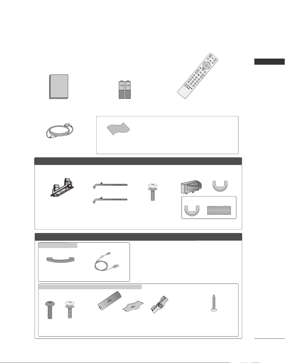
Ensure that the following accessories are included with your TV. If an accessory is missing, please contact the
dealer where you purchased the product.
Owner's Manual
Owner’s Manual
Batteries
Remote Control
Power Cord
INFO
M
U
T
E
R
E
T
U
R
N
AV MODE
FA
V
T
V
I
N
P
U
T
P
O
W
E
R
Q
.
M
E
N
U
M
E
N
U
E
N
T
E
R
V
O
L
C
H
123
456
78
0
9
Q
.
V
I
E
W
G
U
I
D
E
P
A
G
E
D
V
D
V
C
R
i
M
A
R
K
FFoorr LLCCDD TTVV mmooddeellss
FFoorr PPllaassmmaa TTVV mm ooddeellss
Cable Management Clip
Bolts for
stand assembly
(Refer to P.16)
* Only wipe spots on the exterior with the polishing cloth.
* Do not wipe roughly when removing stain. Please be cautions of that
excessive pressure may cause scratch or discoloration.
Polishing Cloth
(This feature is not available
for all models.)
(Only 50PG60*, 50/60PG70** )
x 4 x 4
(Only 32LG50*,
32/42LG80**)
Screw for
stand fixing
(Refer to P.16)
Bolts for stand
assembly
(Refer to P.15)
x 4
Cable Holder
Protection cover
(Refer to p.17)
(This accessories can be differ-
ent from the figures shown here
depending on your models.)
(Only 42/50PG30*)
(Only 42PG60*)
Only 42/47LB7DF
(Only 42PG30*,
42PG60*)
Cable Management Clip
USB Extension Cable
Only 32/37/42/47/52LG50**, 42/47/52LG70**, 32/42LG80**
Protection cover
(Refer to p.17)
(This accessories can be different from the figures
shown here depending on your models.)
x 1
x 2
(42PG30*, 42PG60*)
(50PG30*)
or
or
(Only 32/37/42LG50*,
42LG70**, 32/42LG80**)
PREPARATION
8
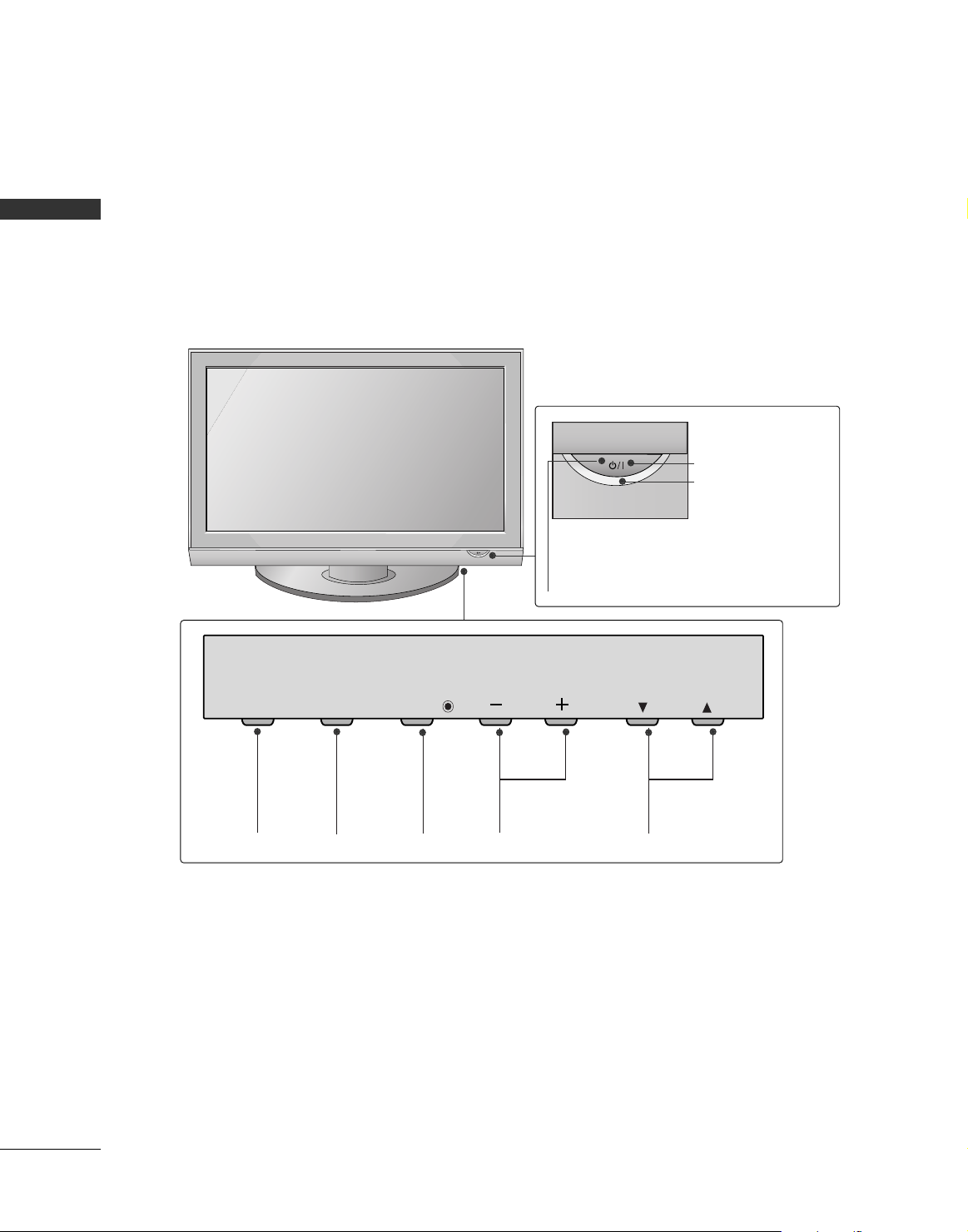
PREPARATION
FRONT PANEL INFORMATION
■
Image shown may differ from your TV.
■
NOTE: If your TV has a protection tape attached, remove the tape.
And then wipe the TV with a cloth (If a polishing cloth is included with your TV, use it).
Plasma TV Models
CHANNEL (
EE, DD
)
Buttons
VOLUME (-,+)
Buttons
MENU
Button
ENTER
Button
INPUT
Button
CH
VOL
MENU
INPUT
ENTER
Remote Control Sensor
POWER Button
Power/Standby Indicator
Illuminates red in standby mode.
Illuminates green when the set is
switched on.
PREPARATION
9
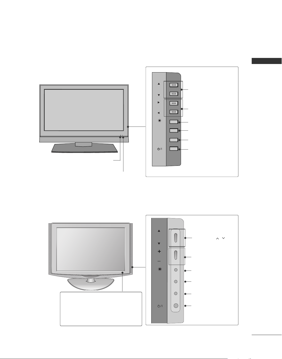
CHANNEL (DD,EE)Buttons
VOLUME (FF, GG) Buttons
ENTER Button
MENU Button
INPUT Button
POWER Button
CHCH
VOLVOL
ENTERENTER
MENUMENU
INPUTINPUT
CH
VOL
ENTER
MENU
INPUT
Remote Control Sensor
Power/Standby Indicator
Illuminates red in standby mode.
Illuminates green when the set is
switched on.
LCD TV Models : 42/47LB7DF
LCD TV Models : 32/42LG80**
Remote Control Sensor
Power/Standby Indicator
• illuminates red in standby mode.
• illuminates blue when the TV is switched on.
Note:
You can adjust
PPoowweerr IInnddiiccaattoorr
in
the
Option menu.
CHANNEL ( , )
Buttons
VOLUME (-,+)
Buttons
ENTER Button
MENU Button
INPUT Button
POWER Button
CHCH
VOLVOL
ENTERENTER
MENUMENU
INPUTINPUT
PREPARATION
10
PREPARATION
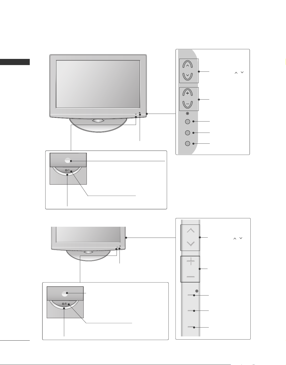
LCD TV Models : 32/37/42/47/52LG50
**
CHANNEL ( , )
Buttons
VOLUME (-,+)
Buttons
ENTER Button
MENU Button
INPUT Button
Intelligent Sensor
Adjusts picture according to the surrounding conditions
POWER Button
Power/Standby Indicator
Illuminates red in standby mode.
Illuminates blue when the set is switched on.
(Can be adjusted using
PPoowweerr IInnddiicc aatt oorr
in
the
Option menu.)
CHANNEL ( , )
Buttons
VOLUME (+, -)
Buttons
ENTER Button
MENU Button
INPUT Button
Intelligent Sensor
Adjusts picture according to the surrounding
conditions
Remote Control Sensor
LCD TV Models :
42/47/52LG70**
POWER Button
Power/Standby Indicator
Illuminates red in standby mode.
Illuminates blue when the set is switched on.
(Can be adjusted
PPoowweerr IInndd iiccaatt oorr
in the
OPTION menu.)
Remote Control Sensor
CH
VOL
ENTER
MENU
INPUT
CH
VOL
ENTER
MENU
INPUT
PREPARATION
11
10
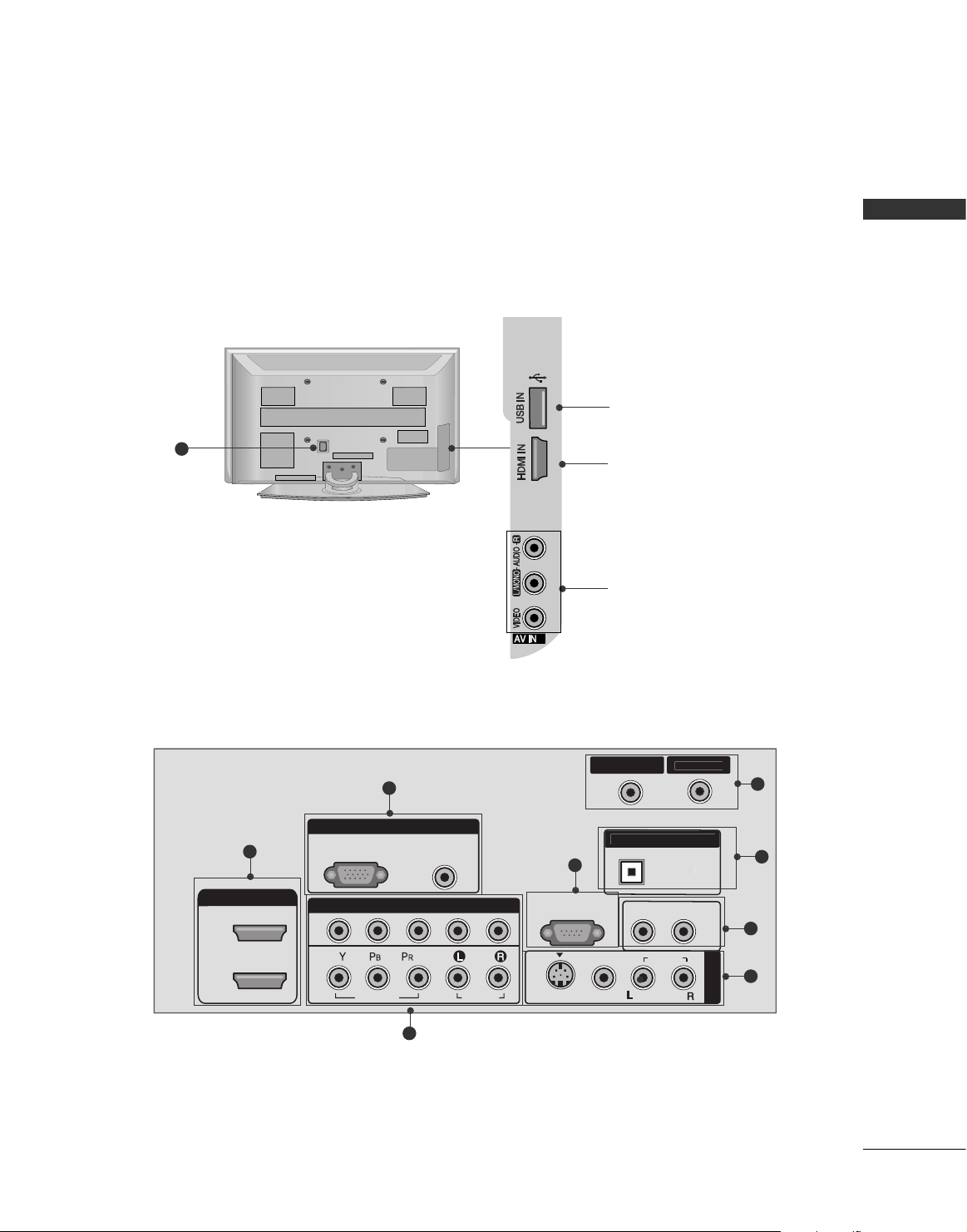
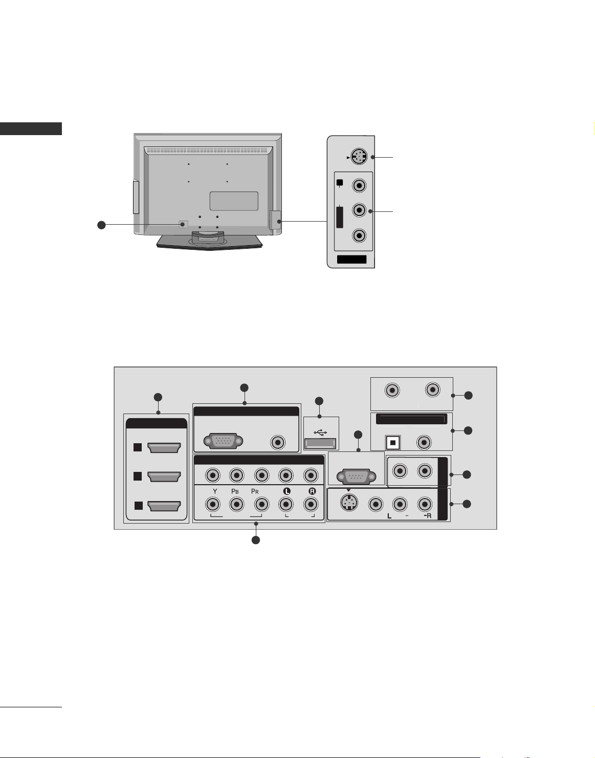
BACK PANEL INFORMATION
■
Here shown may be somewhat different from your TV.
Plasma TV Models
USB Input
HDMI Input
Connect a HDMI signal to
HDMI IN.
AUDIO/VIDEO Input
Connect audio/video output from an external device
to these jacks.
L
T
N
1
3
2
5
6
7
8
9
3
2
CABLE I
AV IN 1
HDMI/DVI IN
2
1
RGB(PC)
2
1
RGB IN
AUDIO
(RGB/DVI)
COMPONENT IN
VIDEO
AUDIO
DIGITAL AUDIO OU
RS-232C IN
(CONTROL & SERVICE)
S-VIDEO
VIDEO
OPTICA
AUDIO OUT
AUDIO
(
)
MONO
PREPARATION
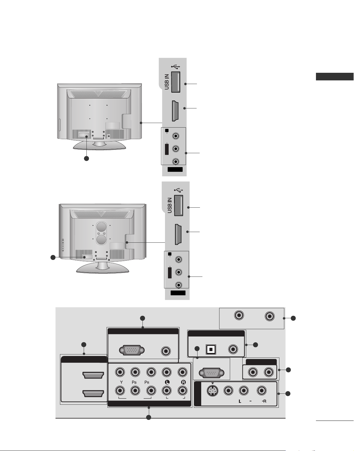
12
PREPARATION
R
10
LCD TV Models : 42/47LB7DF
RGB IN
COMPONENT IN
AUDIO
(RGB/DVI)
RGB(PC)
1
2
RS-232C IN
(CONTROL & SERVICE)
VIDEO
AUDIO
VIDEO
L
MONO
( )
AUDIO
S-VIDEO
T
AV IN 1
HDMI/DVI IN
1
2
3
AV OUT
AUDIO OUT
USB IN
N
1
3
4
2
5
6
7
8
9
AV IN 2
L/ MONO
R
AUDIO
VIDEO
S-VIDEO
S-VIDEO Input
Connect S-Video out
from an S-VIDEO device.
AUDIO/VIDEO Input
Connect audio/video
output from an external
device to these jacks.
CABLE I
DIGITAL AUDIO OU
OPTICALCOAXIA
PREPARATION
13
10
RGB IN
COMPONENT IN
AUDIO
(RGB/DVI)
RGB(PC)
CABLE IN
1
2
RS-232C IN
(CONTROL & SERVICE)
VIDEO
AUDIO
OPTICAL COAXIAL
DIGITAL AUDIO OUT
AUDIO OUT
AV IN 1
HDMI/DVI IN
2
1
VIDEO
MONO
( )
AUDIO
S-VIDEO
ANTENNA IN
1
2
6
7
9
8
3
L/ MONO
R
AUDIO
HDMI IN 3
VIDEO
S-VIDEO
AV IN 2
L/L/MONOMONO
R
AUDIOAUDIO
HDMI IN 3HDMI IN 3
VIDEOVIDEO
LCD TV Models : 32/37/42/47/52LG50
**,
42/47/52LG70**
USB Input
HDMI Input
Connect a HDMI signal
to HDMI IN.
AUDIO/VIDEO Input
Connect audio/video
output from an external
device to these jacks.
5
LCD TV Models : 32/42LG80**
10
L/ MONO
R
AUDIO
HDMI IN 3
VIDEO
S-VIDEO
AV IN 2
L/L/MONOMONO
R
AUDIOAUDIO
HDMI IN 3HDMI IN 3
VIDEOVIDEO
USB Input
HDMI Input
Connect a HDMI signal
to HDMI IN.
AUDIO/VIDEO Input
Connect audio/video
output from an external
device to these jacks.

PREPARATION
14
PREPARATION
HDMI/DVI IN
Connect a HDMI signal to 1, 2 (or 3).
Or DVI (VIDEO) signal to the 1, 2 or 3 port with a
DVI to HDMI cable.
COMPONENT IN
Connect a component video/audio device to these
jacks.
RGB (PC)
Connect the output from a PC.
AUDIO (RGB/DVI)
Connect the audio from a PC or DTV.
USB INPUT
RS-232C IN (CONTROL & SERVICE) PORT
Connect to the RS-232C port on a PC.
ANTENNA IN/CABLE IN
Connect over-the air signals to this jack.
Connect cable signals to this jack.
DIGITAL AUDIO OUT ( or DIGITAL AUDIO OUT
COAXIAL)
Connect digital audio to various types of equipment.
Note: In standby mode, these ports do not work.
AUDIO OUT
Connect analog audio to various types of equipment.
AV (Audio/Video) IN 1
Connect audio/video output from an external
device to these jacks.
S-VIDEO
Connect S-Video out from an S-VIDEO device.
Power Cord Socket
For operation with AC power.
Caution: Never attempt to operate the TV on DC
power.
2
3
4
5
6
7
8
9
10
1
PREPARATION
15
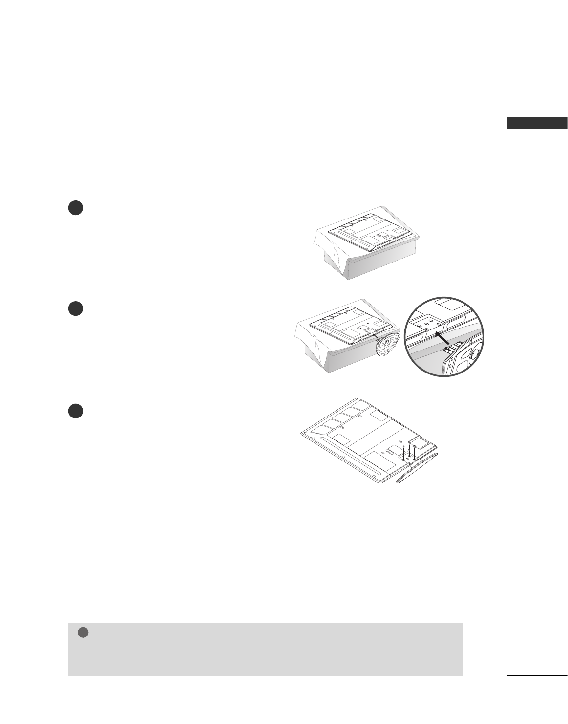
STAND INSTALLATION
■
Image shown may differ from your TV
Plasma TV Models :
Only 42PG60*, 42PG30*
Carefully place the TV screen side down on a
cushioned surface to protect the screen from
damage.
Assemble the TV as shown.
Fix the 4 bolts securely using the holes in the
back of the TV.
1
2
3
GG
When assembling the desk type stand, check whether the bolt is fully tightened. (If not tightened
fully, the product can tilt forward after the product installation). If you tighten the bolt with excessive
force, the bolt can deviate from abrasion of the tightening part of the bolt.
NOTE
!
PREPARATION
16
PREPARATION
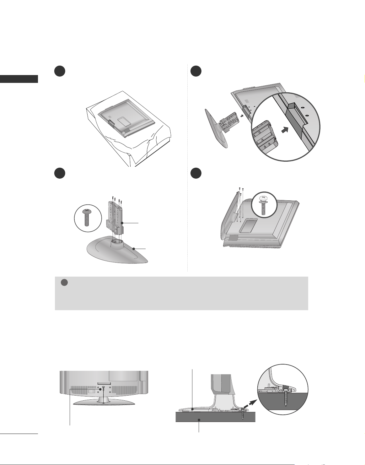
1 3
4
Carefully place the TV screen side down on a
cushioned surface to protect the screen from
damage.
2
Assemble the parts of the
SS ttaa nn dd BBoo ddyy
with
the
CC oovvee rr BBaa ssee
of the TV.
Assemble the TV as shown.
Fix the 4 bolts securely using the holes in the
back of the TV.
SS TTAANNDD BBOODD YY
CC OOVVEERR BBAASSEE
LCD TV Models : 32/37/42LG50
**,
42LG70**, 32/42LG80**
ATTACHING THE TV TO A DESK (Only 32LG50*, 42LG70**, 32/42LG80**)
If you wish to attach the TV to a desk, it must be securely fastened to the desk using a metal screw (as shown
below). Failure to securely attach the TV may result in the TV falling: which may cause damage to the TV and
serious personal injury.
1-Screw
(provided as parts of the product)
Desk
Stand
GG
When assembling the desk type stand, check whether the bolt is fully tightened. (If not tightened
fully, the product can tilt forward after the product installation). If you tighten the bolt with excessive
force, the bolt can deviate from abrasion of the tightening part of the bolt.
NOTE
!
■
Image shown may differ from your TV.
PREPARATION
17
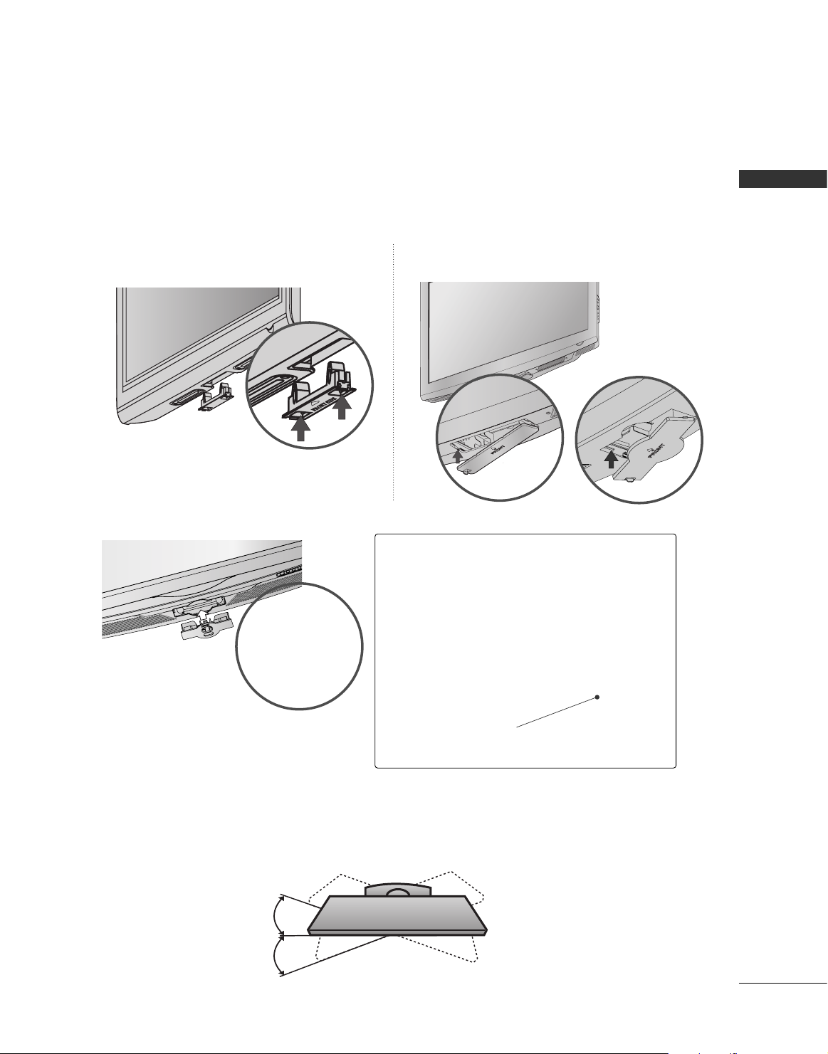
SWIVEL STAND ( Except 42/47LB7DF)
After installing the TV, you can adjust the TV set manually to the left or right direction by 20 degrees to suit
your viewing position.
PROTECTION COVER ( Except 42/47LB7DF)
■
Image shown may differ from your TV.
After removing the stand, install the included
pp rroo tteeccttiioonn cc oovvee rr
over the hole for the stand.
Press the
PPRROOTTEECCTTII OONN CCOOVVEERR
into the TV until you hear it click.
Plasma TV Models
LCD TV Models : 32/37/42/47/52LG50**,
42/47/52LG70**, 42LG80**
Detech the protection cover after pressing the
left/right buttons.
A
LCD TV Models : 32LG80**
How to remove the portection cover
GG
Press the A part of protection cover as shown
and pull it backward.

PREPARATION
18
PREPARATION
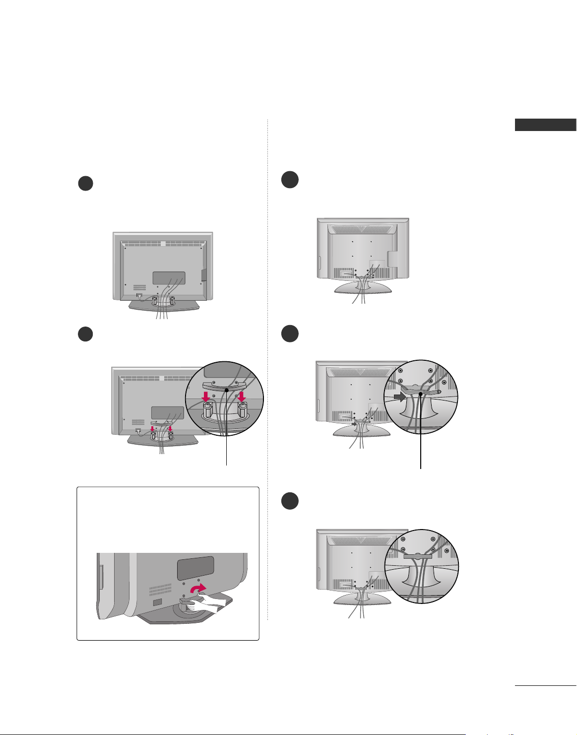
CABLE MANAGEMENT
■
Here shown may be somewhat different from your TV.
Plasma TV Models
GG
Do not hold the CABLE MANAGEMENT CLIP when moving the TV.
- If the TV is dropped, you may be injured or the product may be broken.
NOTE
!
50PG60*, 50/60PG70**
42PG60*, 42/50PG30*
CABLE MANAGEMENT CLIP
CABLE HOLDER
Connect the cables as necessary.
To connect additional equipment, see the
EXTERNAL EQUIPMENT SETUP section.
1
Install the CABLE MANAGEMENT CLIP as
shown.
If your TV has CABLE HOLDER, fix it as
shown and bundle the cables.
2
How to remove the
CABLE MANAGEMENT CLIP
GG
Hold the CABLE MANAGEMENT CLIP with
both hands and pull it upward.
CABLE MANAGEMENT CLIP
CABLE MANAGEMENT CLIP
How to remove the
CABLE MANAGEMENT CLIP
GG
Hold the CABLE MANAGEMENT CLIP with
both hands and pull it upward.
Connect the cables as necessary.
To connect additional equipment, see the
EXTERNAL EQUIPMENT SETUP section.
Install the CABLE MANAGEMENT CLIP as
shown.
1
2
Separate CABLE MANAGEMENT CLIP
from TV by pressing two latches.
* For the 42PG60* model: First, press the cable man-
agement. Hold the CABLE MANAGEMENT CLIP with
both hands and pull it upword.
42PG60*
42PG30*
50PG30*
PREPARATION
19
32/37/42/47/52LG50
**,
42/47/52LG70**, 32/42LG80**
Connect the cables as necessary.
To connect additional equipment, see the
EXTERNAL EQUIPMENT SETUP section.
1
Install the CABLE MANAGEMENT CLIP as
shown.
2
CABLE MANAGEMENT CLIP
Put the cables inside the CABLE MANAGEMENT
CLIP and snap it closed.
3
42/47LB7DF
Connect the cables as necessary.
To connect additional equipment, see the
EXTERNAL EQUIPMENT SETUP section.
Install the
CCAABBLLEE MMAANNAAGGEEMMEENNTT CCLLIIPP
as shown.
How to remove the
CABLE MANAGEMENT CLIP
GG
Hold the
CC AA BB LL EE MMAANNAAGGEEMMEENN TT CC LLII PP
with both hands and pull it backward.
CABLE MANAGEMENT CLIP
1
2
LCD TV Models
PREPARATION
20
PREPARATION
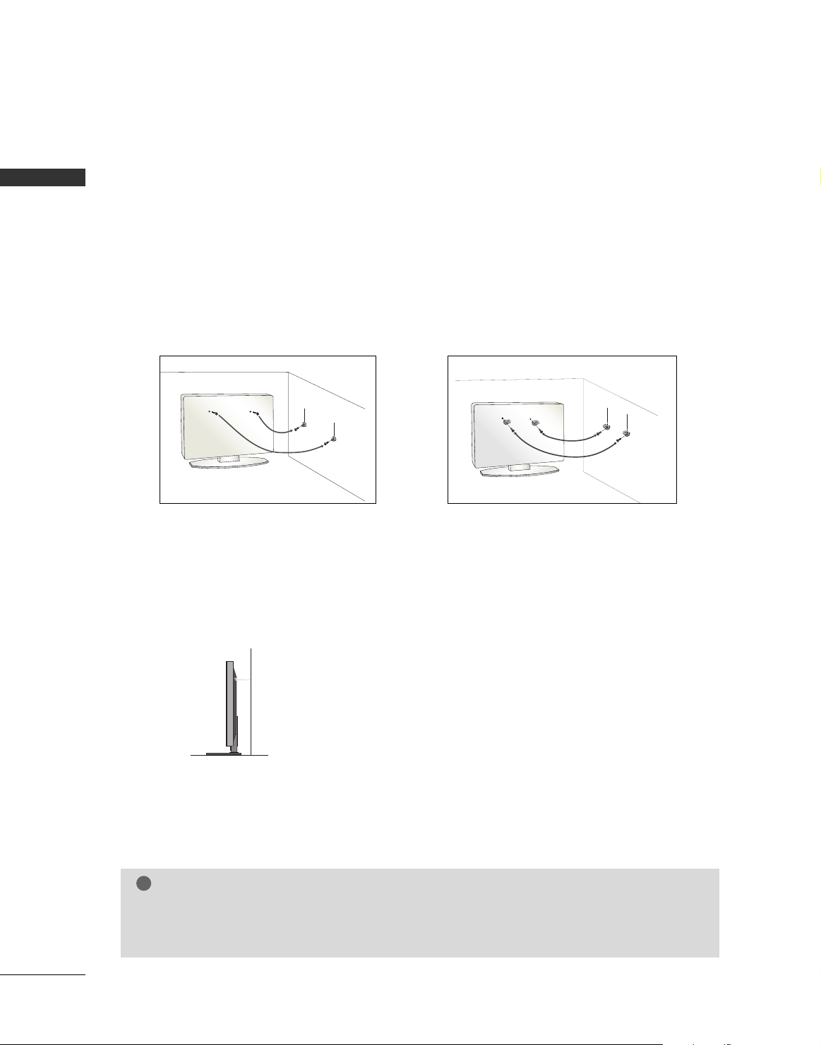
SECURING THE TV TO THE WALL FALL OVER.
This feature is not available for all models.
Here shown may be somewhat different from your TV.
■
Position the TV close to the wall to avoid the possibility of it falling when pushed.
■
The instructions shown below are a safer way to set up the TV, which is to fix it to the wall, avoiding the
possibility of it falling forwards if pulled. This will prevent the TV from falling forward and causing injury.
This will also prevent the TV from damage. Ensure that children do not climb or hang from the TV.
■
You should purchase necessary components to prevent TV from falling off of the stand.
■
Insert the eye-bolts (or TV brackets and bolts) to tighten the product to the wall as shown in the picture.
*If your product has the bolts in the eye-bolts position before inserting the eye-bolts, loosen the bolts.
Secure the wall brackets with the bolts (not provided as parts of the product, must purchase separately) to
the wall. Match the height of the bracket that is mounted on the wall to the holes in the product.
Ensure the eye-bolts or brackets are tightened securely.
■
Use a sturdy rope (not provided as parts of the product, must purchase separately) to tie the product. It is safer to tie the rope so it
becomes horizontal between the wall and the product.
NOTE
!
G
When moving the TV undo the cords first.
G
Use a platform or cabinet strong and large enough to support the size and weight of the TV.
G
To use the TV safely make sure that the height of the bracket on the wall and on the TV is the same.
PREPARATION
21
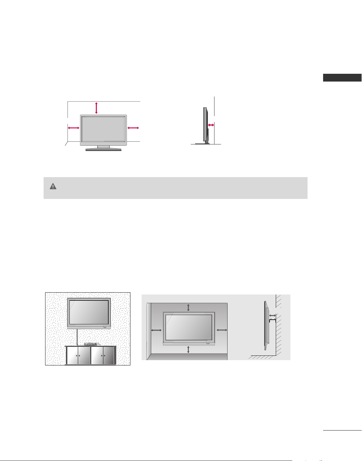
DESKTOP PEDESTAL INSTALLATION
For adequate ventilation allow a clearance of 4” (10cm) all around the TV.
WALL MOUNT: HORIZONTAL INSTALLATION
For adequate ventilation allow a clearance of 4” (10cm) all around the TV. Detailed installation
instructions are available from your dealer, see the optional Tilt Wall Mounting Bracket Installation
and Setup Guide.
■
This part mainly use picture for Plasma TV model.
Here shown may be somewhat different from your TV.
4 inches
4 inches
4 inches
4 inches
4 inches
4 inches
4 inches
4 inches
4 inches
GG
Ensure adequate ventilation by following the clearance recommendations.
GG
Do not mount near or above any type of heat source.
CAUTION
22
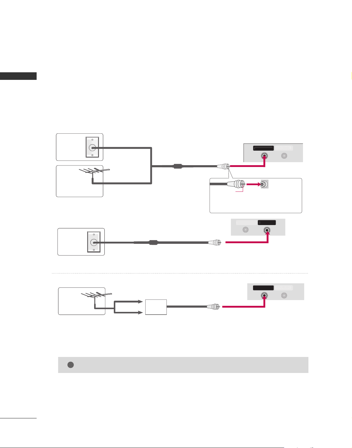
ANTENNA OR CABLE CONNECTION
1. Antenna (Analog or Digital)
Wall Antenna Socket or Outdoor Antenna without a Cable Box Connections.
For optimum picture quality, adjust antenna direction if needed.
2. Cable
Wall
Antenna
Socket
Outdoor
Antenna
(VHF, UHF)
Cable TV
Wall Jack
Multi-family Dwellings/Apartments
(Connect to wall antenna socket)
RF Coaxial Wire (75 ohm)
RF Coaxial Wire (75 ohm)
Single-family Dwellings /Houses
(Connect to wall jack for outdoor antenna)
Be careful not to bend the copper wire
when connecting the antenna.
Copper Wire
GG
The TV will let you know when the analog, cable, and digital channel scans are complete.
NOTE
!
■
To improve the picture quality in a poor signal area, please purchase a signal amplifier and install properly.
■
If the antenna needs to be split for two TV’s, install a 2-Way Signal Splitter.
■
If the antenna is not installed properly, contact your dealer for assistance.
Antenna
UHF
Signal
Amplifier
VHF
CABLE IN
N
CABLE IN
■
Here shown may be somewhat different from your TV.
ii..ee))
PP llaa ss mmaa TTVV
MMoo dd eell ss
ii..ee))
PP llaa ss mmaa TTVV
MMoo dd eell ss
ii..ee))
PP llaa ss mmaa TTVV
MMoo dd eell ss
PREPARATION
PREPARATION
■
To prevent damage do not connect to the power outlet until all connections are made between the devices.
CABLE I
EXTERNAL EQIPMENT SETUP
23
EXTERNAL EQUIPMENT SETUP
HD RECEIVER SETUP
This TV can receive Digital Over-the-air/Cable signals without an external digital set-top box. However, if you do
receive digital signals from a digital set-top box or other digital external device, refer to the figure as shown below.
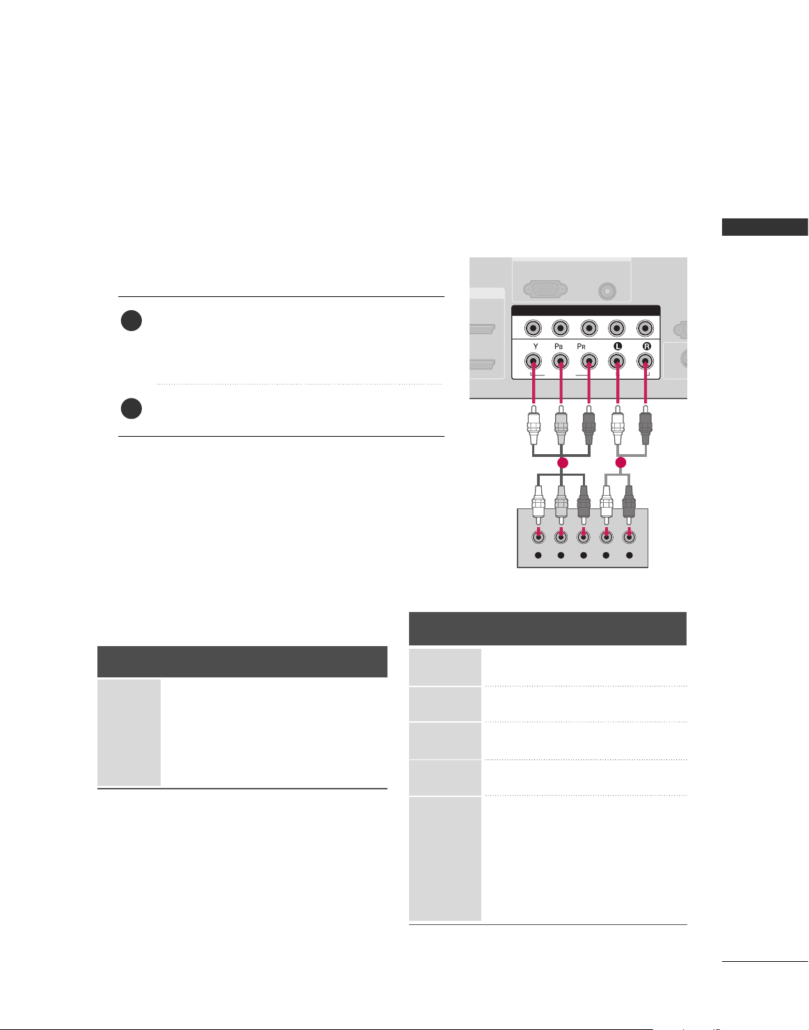
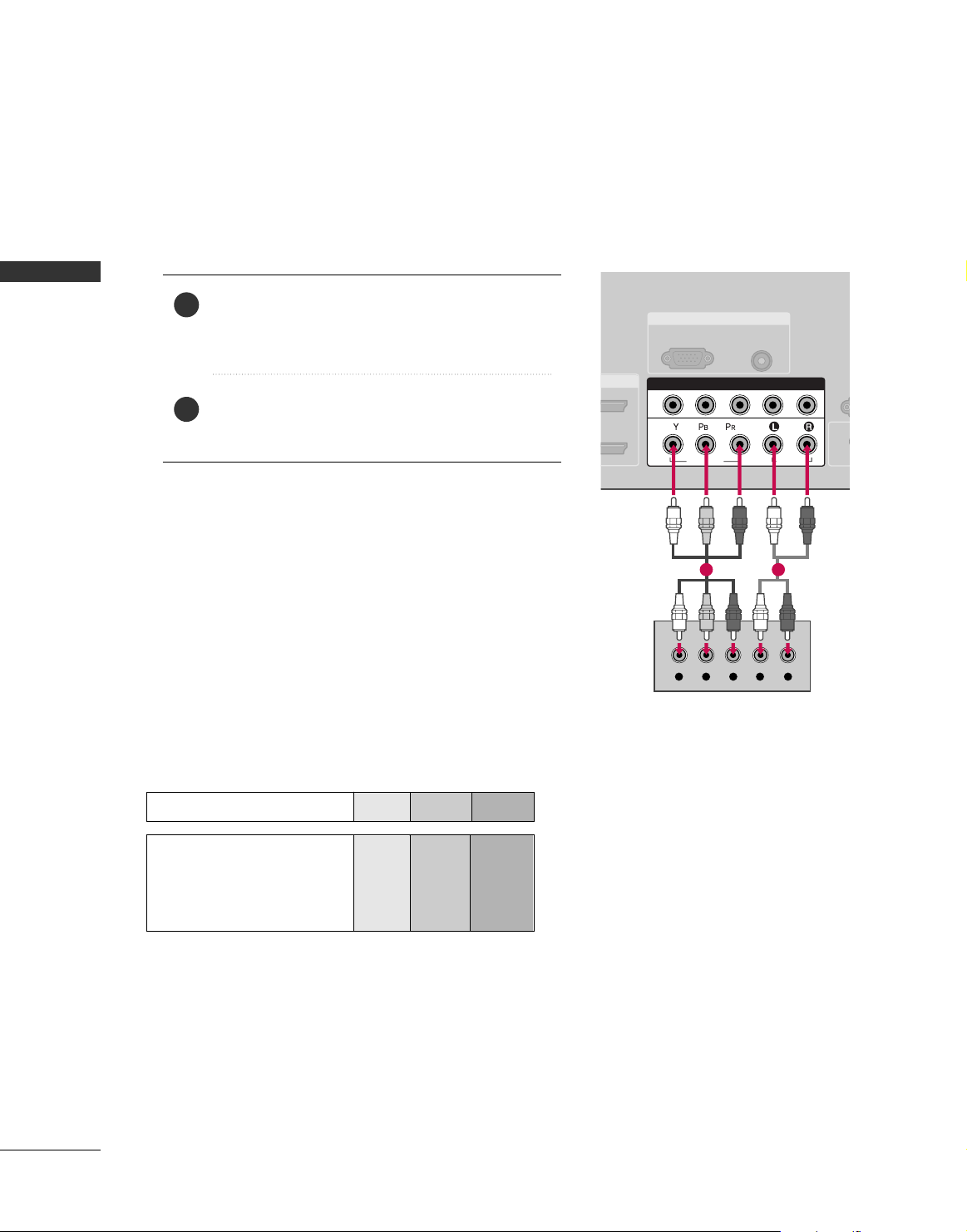
Component Connection
1. How to connect
Connect the video outputs (Y, PB, PR
)
of the digital set
top box to the
CC OO MMPPOONNEENNTT IINN VVII DD EE OO 11
jacks on
the TV. Match the jack colors (Y = green, P
B = blue, and
P
R = red).
Connect the audio output of the digital set-top box to
the
CC OO MMPPOONNEENNTT IINN AAUUDDIIOO 11
jacks on the TV.
2
1
2. How to use
■
Turn on the digital set-top box.
(
Refer to the owner’s manual for the digital set-top box.
)
■
Select
CC oomm pp oonneenntt 11
input source on the TV with using
the
II NN PP UUTT
button on the remote control.
■
If connected to
CC OO MMPPOONNEE NN TT IINN22
input, select
CC oomm ppoonneenntt 22
input source on the TV.
■
To prevent the equipment damage, never plug in any power cords until you have finished connecting all equipment.
■
This part of EXTERNAL EQUIPMENT SETUP mainly use picture for Plasma TV model.
RGB IN
AUDIO
(RGB/DVI)
RGB(PC)
RS
(CONTR
( )
S-VIDEO
COMPONENT IN
1
2
VIDEO
AUDIO
Y L RPB PR
1
2
Signal
480i
480p
720 p
10 8 0 i
1080p
Component 1, 2
Yes
Yes
Yes
Yes
Yes
HDMI1, 2 or 3
No
Yes
Yes
Yes
Yes
Y, CB/PB, CR/PR
Horizontal Vertical
Frequency(KHz)Frequency(Hz
)
15.73 59.94
15.73 60.00
31.47 59.94
31.47 60.00
44.96 59.94
45.00 60.00
33.72 59.94
33.75 60.00
26.97 23.94
27.00 24.00
33.71 29.97
33.75 30.00
67. 432 59.939
67.50 60.00
56.25 50.00
28.125 25.00
Resolution
720 x 480i
720 x 480p
128 0 x 7 2 0 p
1920 x 108 0 i
1920 x 1080p
Supported Resolutions
24
EXTERNAL EQUIPMENT SETUP
EXTERNAL EQIPMENT SETUP
RGB IN
COMPONENT IN
AUDIO
(RGB/D
RGB(PC)
1
2
VIDEO
( )
HDMI/DVI IN
1
2
HDMI-DTV OUTPUT
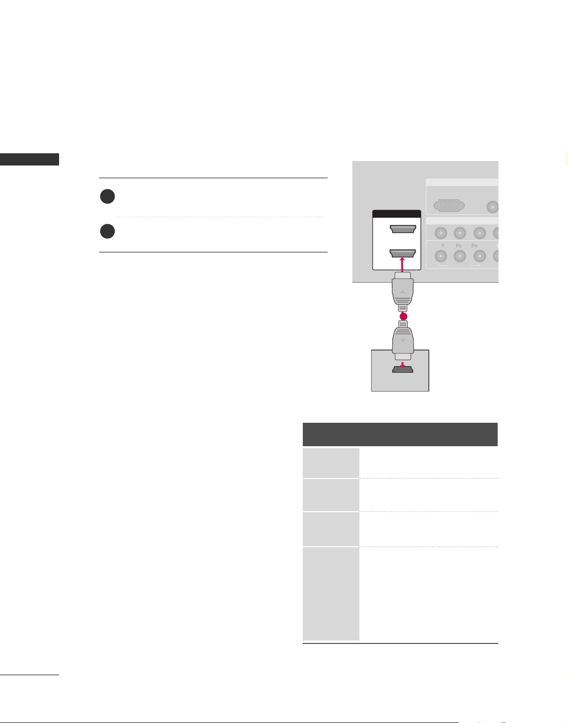
HDMI Connection
Connect the digital set-top box to
HHDDMMII//DDVVII IINN 11
,
22
or
HHDDMMII IINN 33
jack on the TV.
No separated audio connection is necessary.
HDMI supports both audio and video.
1. How to connect
2. How to use
■
Turn on the digital set-top box.
(
Refer to the owner’s manual for the digital set-top box.
)
■
Select
HHDDMMII11,HHDDMMII22orHHDDMMII33
input source on the TV
with using the
IINNPPUUTT
button on the remote control.
2
1
1
HDMI-DTV mode
Horizontal Vertical
Frequency(KHz)Frequency(Hz
)
31.47 60.00
31.47 59.94
44.96 59.94
45.00 60.00
33.72 59.94
33.75 60.00
26.97 23.94
27.00 24.00
33.71 29.97
33.75 30.00
67.432 59.939
67.50 60.00
56.25 50.00
28.125 25.00
Resolution
720 x 480p
128 0 x 7 20 p
1920 x 108 0 i
1920 x 108 0 p
EXTERNAL EQIPMENT SETUP
25
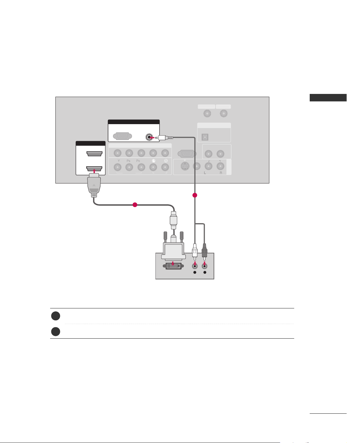
DVI to HDMI Connection
( )
COMPONENT IN
AV IN 1
1
2
RS-232C IN
(CONTROL & SERVICE)
VIDEO
AUDIO
AUDIO OUT
OPTICAL
VIDEO
MONO
( )
AUDIO
S-VIDEO
HDMI/DVI IN
1
2
RGB IN
AUDIO
(RGB/DVI)
L R
DVI-DTV OUTPUT
RGB(PC)
DIGITAL AUDIO OUT
N
Connect the DVI output of the digital set-top box to the
HHDDMMII //DDVVII IINN11, 22
or
HHDDMMII IINN33
jack on the TV.
Connect the audio output of the digital set-top box to the
AAUUDDIIOO ((RRGGBB//DDVVII
))
jack on the TV.
1. How to connect
■
Turn on the digital set-top box. (Refer to the owner’s manual for the digital set-top box.
)
■
Select
HHDDMMII11,HHDDMMII22orHHDDMMII33
input source on the TV with using the
IINNPPUUTT
button on the
remote control.
2. How to use
2
1
1
2
CABLE I
EXTERNAL EQIPMENT SETUP
26
EXTERNAL EQUIPMENT SETUP
DVD SETUP
Component Connection
Component Input ports
Connect a DVD player to the component input ports as shown below.
Component ports on the TV
YPB PR
Video output ports
on DVD player
Y
Y
Y
Y
P
B
B-Y
Cb
Pb
P
R
R-Y
Cr
Pr
Connect the video outputs (Y, PB, PR
)
of the DVD to the
CC OO MMPPOONNEENNTT IINN VVII DD EE OO11
jacks on the TV.
Match the jack colors (Y = green, P
B = blue, and PR = red
)
.
Connect the audio outputs of the DVD to the
CC OO MMPPOONNEENNTT IINN AAUUDDIIOO 11
jacks on the TV.
1. How to connect
2. How to use
■
Turn on the DVD player, insert a DVD.
■
Select
CC oomm pp oonneenntt 11
input source on the TV with using
the
II NN PP UUTT
button on the remote control.
■
If connected to
CC OO MMPPOONNEENNTT IINN 22
input, select
CC oomm ppoonneenntt 22
input source on the TV.
■
Refer to the DVD player's manual for operating instructions.
2
1
RGB IN
AUDIO
(RGB/DVI)
RGB(PC)
R
(CONT
( )
S-VIDEO
COMPONENT IN
1
2
VIDEO
AUDIO
Y L RPB PR
1 2
EXTERNAL EQIPMENT SETUP
27
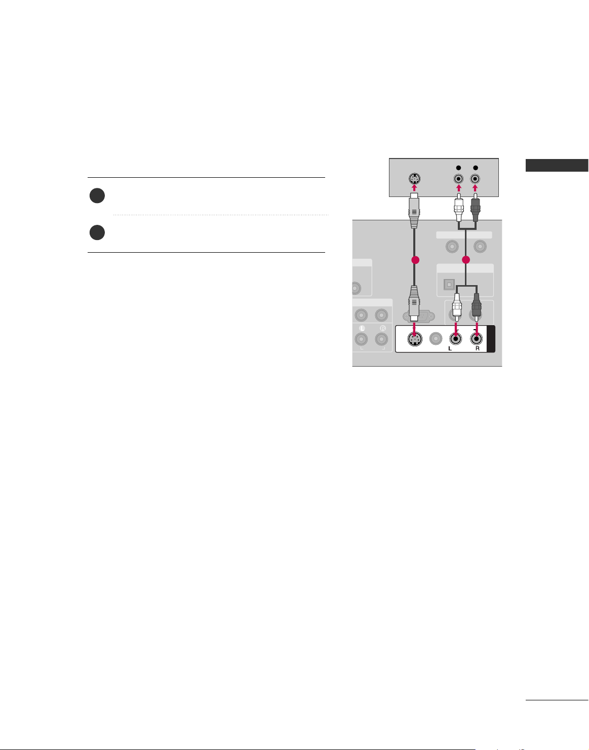
S-Video Connection
Connect the S-VIDEO output of the DVD to the
SS -- VV II DD EE OO
input on the TV.
Connect the audio outputs of the DVD to the
AAUU DD IIOO
input jacks on the TV.
1. How to connect
2. How to use
■
Turn on the DVD player, insert a DVD.
■
Select
AAVV 11
input source on the TV with using the
II NN PP UUTT
button on the remote control.
■
If connected to
AAVV IINN 22
, select
AAVV 22
input source.
■
Refer to the DVD player's manual for operating instructions.
2
1
( )
RS-232C IN
(CONTROL & SERVICE)
AUDIO
AUDIO OUT
OPTICAL
MONO
( )
AUDIO
S-VIDEO
AV IN 1
VIDEO
L R
S-VIDEO
AUDIO
DIGITAL AUDIO OUT
ANTENNA IN
CABLE IN
1
2
EXTERNAL EQIPMENT SETUP
28
EXTERNAL EQUIPMENT SETUP
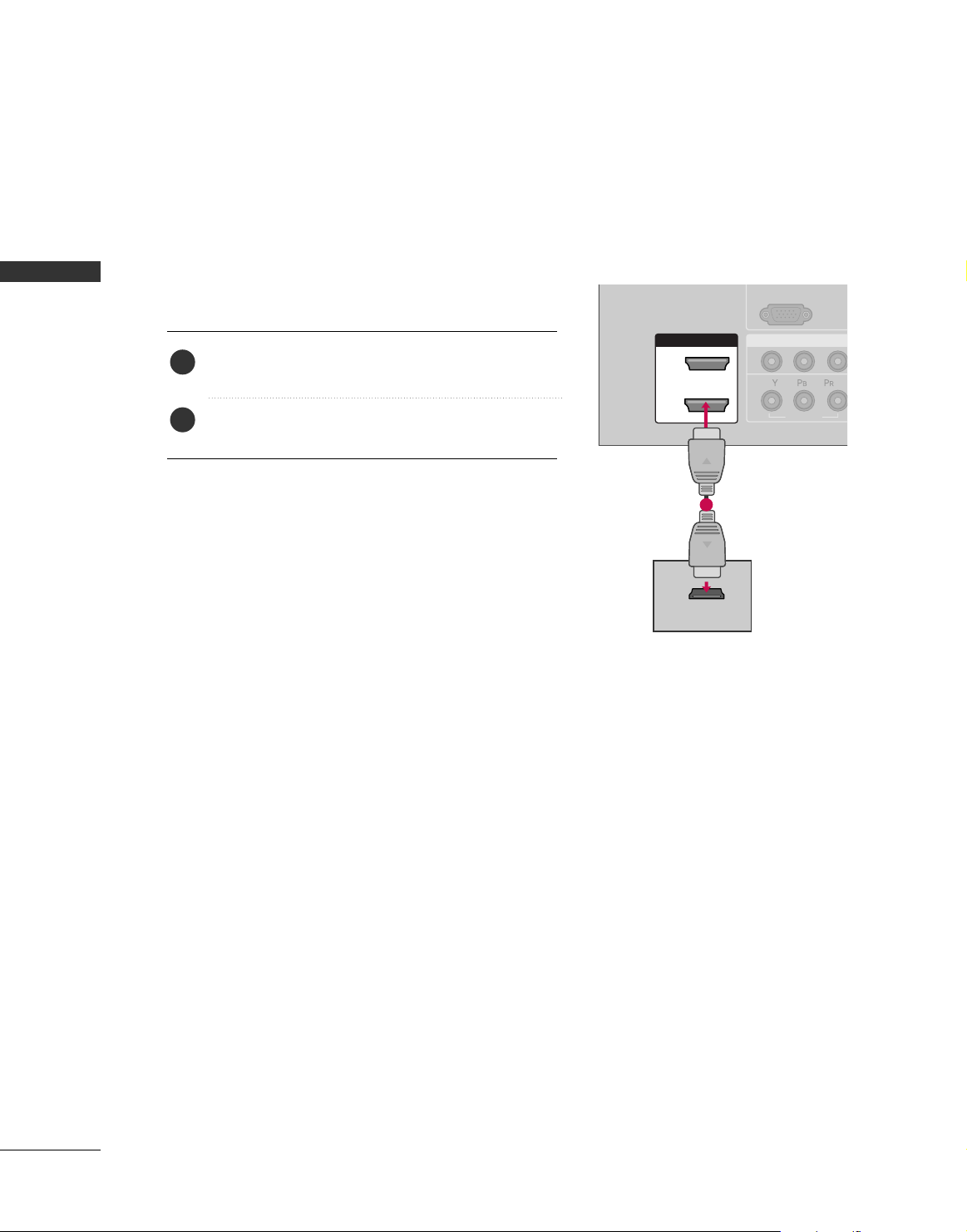
HDMI Connection
Connect the HDMI output of the DVD to the
HHDDMMII //DDVV II IINN 11, 22
, or
HHDDMMII IINN 33
jack on the TV.
No separated audio connection is necessary.
HDMI supports both audio and video.
1. How to connect
2. How to use
■
Select
HHDDMMII11,HHDDMMII22
,or
HHDDMMII33
input source on the TV
with using the
II NN PP UUTT
button on the remote control.
■
Refer to the DVD player's manual for operating instructions.
2
1
COMPONEN
A
(R
RGB(PC)
1
2
VIDEO
( )
HDMI/DVI IN
1
2
HDMI-DVD OUTPUT
1
 Loading...