

LG 50PC3D Schematic

PLASMA TV
SERVICE MANUAL
CAUTION
BEFORE SERVICING THE CHASSIS,
READ THE SAFETY PRECAUTIONS IN THIS MANUAL.
CHASSIS :PA-63E
MODEL : 50PC3D 50PC3D-UE
CANADA : http//biz.lgservice.com
USA : http//www.lgservice.com
: http//biz.lgservice.com
- 2 -
SAFETY PRECAUTIONS
Many electrical and mechanical parts in this chassis have special safety-related characteristics. These parts are identified by in
the Schematic Diagram and Replacement Parts List.
It is essential that these special safety parts should be replaced with the same components as recommended in this manual to
prevent X-RADIATION, Shock, Fire, or other Hazards.
Do not modify the original design without permission of manufacturer.
General Guidance
An lsolation Transformer should always be used during
the servicing of a receiver whose chassis is not isolated from
the AC power line. Use a transformer of adequate power rating
as this protects the technician from accidents resulting in
personal injury from electrical shocks.
It will also protect the receiver and it's components from being
damaged by accidental shorts of the circuitary that may be
inadvertently introduced during the service operation.
If any fuse (or Fusible Resistor) in this monitor is blown, replace
it with the same specified type.
When replacing a high wattage resistor (Oxide Metal Film
Resistor, over 1W), keep the resistor 10mm away from PCB.
Keep wires away from high voltage or high temperature parts.
Leakage Current Cold Check(Antenna Cold Check)
With the instrument AC plug removed from AC source,
connect an electrical jumper across the two AC plug prongs.
Place the AC switch in the on positioin, connect one lead of
ohm-meter to the AC plug prongs tied together and touch other
ohm-meter lead in turn to each exposed metallic parts such as
antenna terminals, phone jacks, etc.
If the exposed metallic part has a return path to the chassis, the
measured resistance should be between 1MΩ and 5.2MΩ.
When the exposed metal has no return path to the chassis the
reading must be infinite.
An other abnormality exists that must be corrected before the
receiver is returned to the customer.
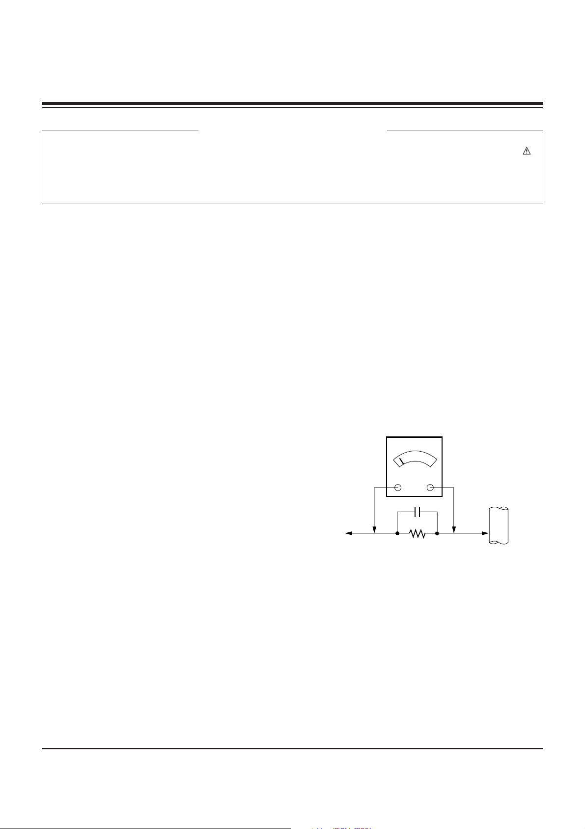
Leakage Current Hot Check (See below Figure)
Plug the AC cord directly into the AC outlet.
Do not use a line Isolation Transformer during this check.
Connect 1.5K/10watt resistor in parallel with a 0.15uF capacitor
between a known good earth ground (Water Pipe, Conduit, etc.)
and the exposed metallic parts.
Measure the AC voltage across the resistor using AC
voltmeter with 1000 ohms/volt or more sensitivity.
Reverse plug the AC cord into the AC outlet and repeat AC
voltage measurements for each esposed metallic part. Any
voltage measured must not exceed 0.75 volt RMS which is
corresponds to 0.5mA.
In case any measurement is out of the limits sepcified, there is
possibility of shock hazard and the set must be checked and
repaired before it is returned to the customer.
Leakage Current Hot Check circuit
CANADA: LG Electronics Canada, Inc. 550 Matheson
Boulevard East Mississauga, Ontario L4Z 4G3
USA : LG Customer Interactive Center
P.O.Box 240007, 201 James Record Road Huntsville,
AL 35824
Digital TV Hotline 1-800-243-0000
1.5 Kohm/10W
To Instrument's
exposed
METALLIC PARTS
Good Earth Ground
such as WATER PIPE,
CONDUIT etc.
AC Volt-meter
IMPORTANT SAFETY NOTICE
0.15uF

- 3 -
DESCRIPTION OF CONTROLS...........................................4
SPECIFICATIONS.................................................................8
ADJUSTMENT INSTRUCTIONS ..........................................9
PRINTED CIRCUIT BOARDS.............................................16
BLOCK DIAGRAM...............................................................19
EXPLODED VIEW...............................................................20
EXPLODED VIEW PARTS LIST.........................................21
REPLACEMENT PARTS LIST............................................22
SCHEMATIC DIAGRAM..........................................................
TABLE OF CONTENTS
- 4 -
Controls (Model Name:
Controls (Model Name:
42PC3DU/3DVU/50PC3DU/60PC1D)
42PC3DU/3DVU/50PC3DU/60PC1D)
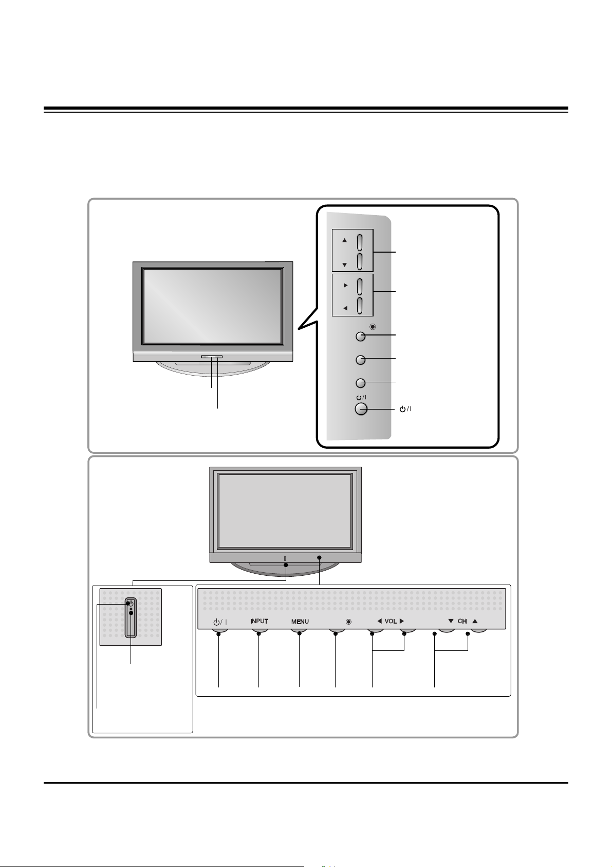
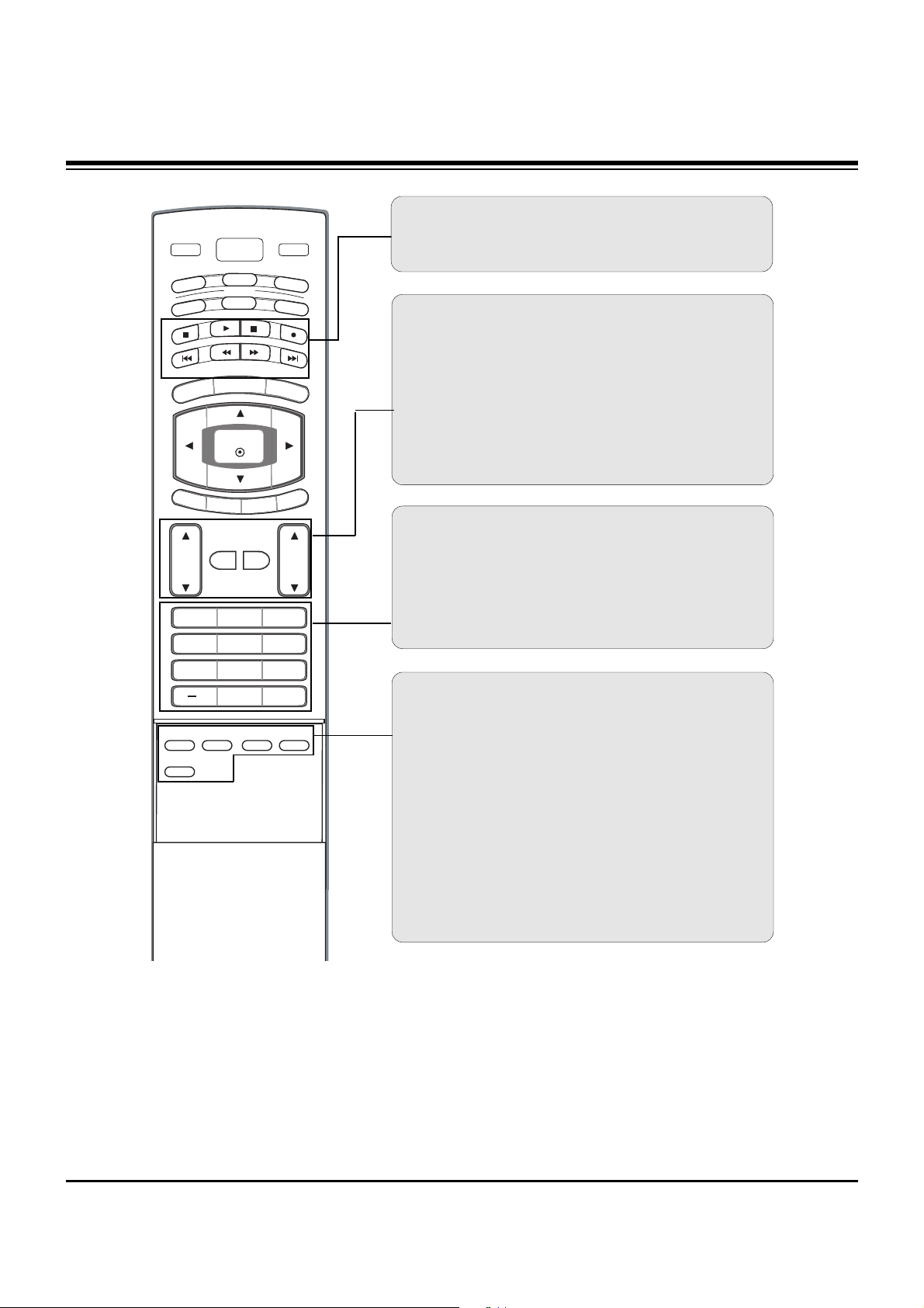
- This is a simplified representation of front panel.
- This picture shown below may be somewhat different from your TV.
POWER
Button
INPUT
Button
ENTER
Button
VOLUME
(
FF,GG
)Buttons
CHANNEL
(
EE,DD
)Buttons
Power Standby Indicator
Illuminates red in stand-
by mode.
Illuminates green when
the set is switched on.
MENU
Button
ENTERENTER
Remote
Control Sensor
CHCH
VVOLOL
ENTERENTER
MENUMENU
INPUTINPUT
CHANNEL (D, E)
Buttons
VOLUME (F,G)
Buttons
ENTER Button
MENU Button
INPUT Button
Remote Control Sensor
Power/Standby Indicator
• illuminates red in standby mode.
• illuminates green when the set is switched on.
(Power) Button
42/50PC3DU/42PC3DVU
60PC1D
DESCRIPTION OF CONTROLS
- 5 -
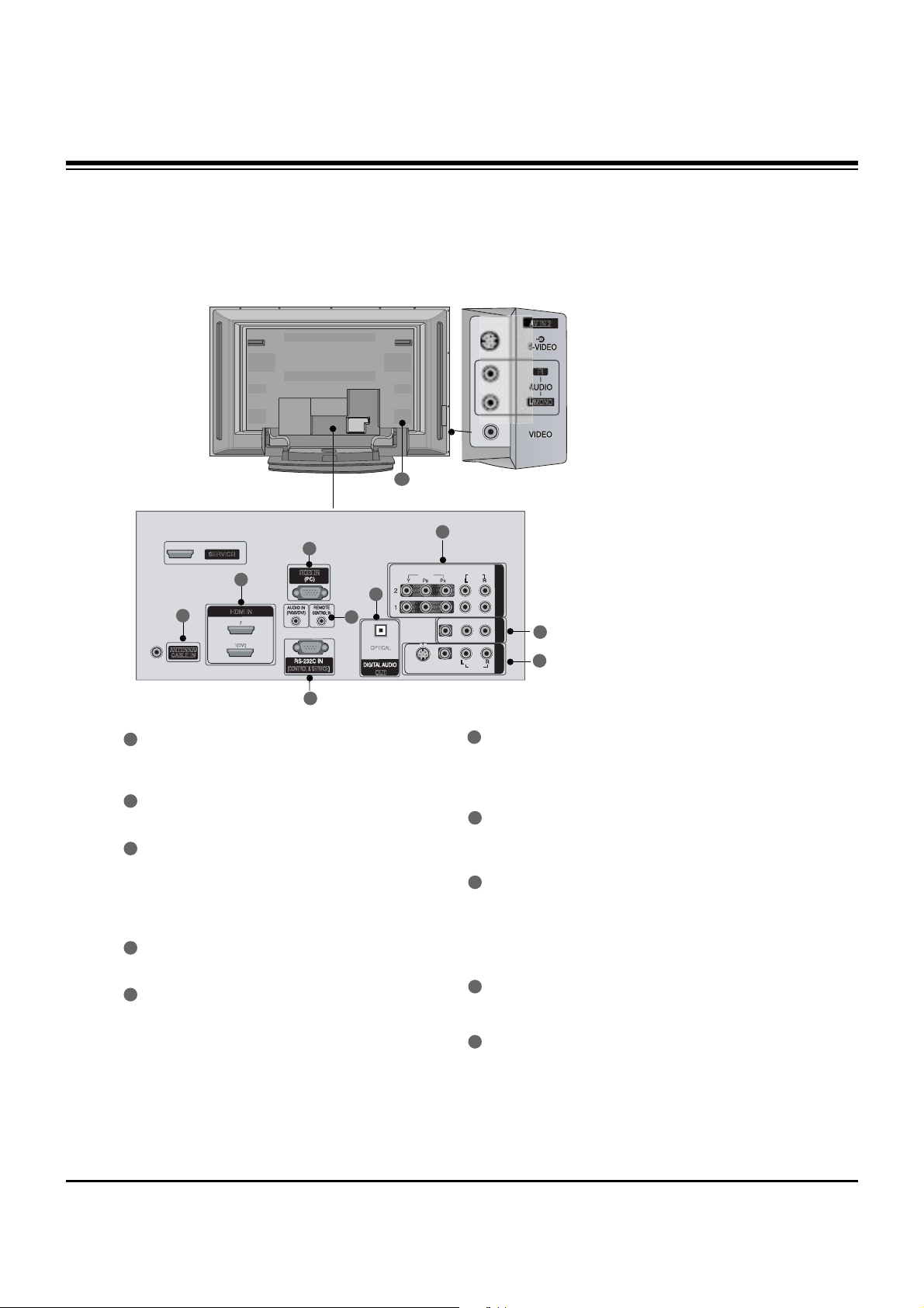
Connection Options
Connection Options
(Model Name: 42PC3DU/3DVU/50PC3DU/60PC1D)
(Model Name: 42PC3DU/3DVU/50PC3DU/60PC1D)
- This picture shown below may be somewhat different from your TV.
/
MONO
VIDEOVIDEO
AUDIOAUDIO
VIDEOVIDEO
AUDIOAUDIO
MONO
( ( ))
S-VIDEOS-VIDEO
AV IN 1AV IN 1
AV OUTAV OUT
ANTENNA/
CABLE IN
(CONTROL & SERVICE)
RGB IN
COMPONENT INCOMPONENT IN
OUT
O
PTICAL
1(DVI)
SERVICE
S-VIDEO Input
Provides better picture quality
than the video input.
AUDIO Input
Connections are available for
listening to stereo sound from
an external device.
VIDEO Input
Connects the video signal from
a video device.
COMPONENT IN
Connect a component video/audio device to
these jacks.
AV OUT
Connect a second TV or monitor.
AV (Audio/Video) IN 1
Connect audio/video output from an external
device to these jacks.
S-VIDEO
Connect S-Video out from an S-VIDEO device.
ANTENNA/CABLE IN
Connect over-the air signals to this jack.
DIGITAL AUDIO OUT
Connect digital audio from various types of
equipment.
Note: In standby mode, these ports do not work.
HDMI IN
Connect a HDMI signal to 1(DVI) or 2.
Or DVI (VIDEO)signal to the 1(DVI) port with
a DVI to HDMI cable.
RGB IN (PC)
Connect the monitor output from a PC to the
appropriate input port.
Remote Control Port
Connect your wired remote control.
AUDIO IN (RGB/DVI)
Connect the monitor output from a PC to the
appropriate input port.
RS-232C IN (CONTROL& SERVICE) PORT
Connect to the RS-232C port on a PC.
Power Cord Socket
For operation with AC power.
Caution:
Never attempt to operate the TV on DC power.
1
2
4
1
7
8
9
10
2
3
4
5
5
6
7
8
3
9
10
6
DESCRIPTION OF CONTROLS
- 6 -
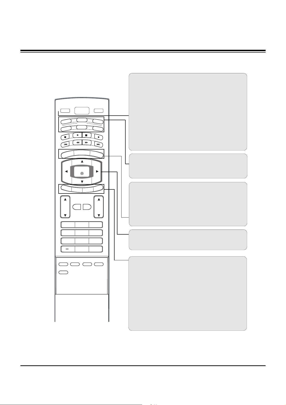
Remote Control Key Functions
Remote Control Key Functions
POWER
Turns your TV or any other programmed equipment on or
off, depending on mode.
VOL
CH
POWER
1 2 3
4 5 6
7 8
0
9
MENU
MUTE
FAV
BRIGHT +
VCR
TV
DVD
ENTER
ADJUST
SAP
EZ SOUND
EZ PIC
CC
FLASHBK
EXIT
TIMER
RATIO
INFO
AUDIO
CABLE
STB
MODE
TV INPUT
INPUT
BRIGHT -
TV INPUT
Rotates the input mode between Antenna and Cable. In AV12, Component 1-2, RGB-DTV (or RGB-PC), HDMI1/DVI, and
HDMI2 input sources, screen returns to the last TV channel.
MODE
Selects the remote operating mode: TV, DVD, VCR, AUDIO,
CABLE, or STB. Select a mode other than TV, for the remote
to operate an external device.
INPUT
External input modes rotate in regular sequence: TV, AV1-2,
Component 1-2, RGB-PC, HDMI1/DVI or HDMI2.
(AV 1-2, Component 1-2, RGB-PC , HDMI1/DVI or HDMI2
input sources are linked automatically, only if these are connected.)
EXIT
Clears all on-screen displays and returns to TV viewing from
any menu.
TIMER
Lets you select the amount of time before your TV turns
itself off automatically.
RATIO
Changes the aspect ratio.
MENU
Brings up the main menu to the screen.
BRIGHT + / -
- Adjust brightness on screen.
- It turns to the default settings brightness by changing mode
source.
THUMBSTICK (Up/Down/Left/Right/ENTER)
Allows you to navigate the on-screen menus and adjust the
system settings to your preference.
INFO
When you watch the TV, information displays on top of the
screen. Not available in Component 1-2, RGB, HDMI1/DVI
and HDMI2 mode.
DESCRIPTION OF CONTROLS
- 7 -
EZ PIC
Selects a factory preset picture mode depending on the viewing environment.
EZ SOUND
Selects the sound appropriate for the program's character.
SAP
Selects MTS sound: Mono, Stereo, and SAP in analog mode.
Change the audio language in DTV mode.
CC
(*In DTV/CADTV mode )
Select a closed caption: Off, CC1~4, Text1~4.
ADJUST
Adjusts screen position, size, and phase in PC mode.
FAV
Use to scroll the Favorite channels.
MUTE
Switches the sound on or off.
CHANNEL UP/DOWN
Selects available channels found with EZ scan and Manual scan.
VOLUME UP/DOWN
Increases/decreases the sound level.
VOL
CH
POWER
1 2 3
4 5 6
7 8
0
9
MENU
MUTE
FAV
BRIGHT +
VCR
TV
DVD
ENTER
ADJUST
SAP
EZ SOUND
EZ PIC
CC
FLASHBK
EXIT
TIMER
RATIO
INFO
AUDIO
CABLE
STB
MODE
TV INPUT
INPUT
BRIGHT -
— (DASH)
Used to enter a program number for multiple program channels such as 2-1, 2-2,etc.
NUMBER BUTTONS
FLASHBK
Returns to the last channel viewed.
VCR/DVD/DVHS/Camcorder BUTTONS
Control some video cassette recorders or DVD players
("RECORD" button is not available for DVD player).
DESCRIPTION OF CONTROLS
- 8 -
60PC1D
(60PC1D-UE)
AC100-240V ~ 50/60Hz
NTSC-M, ATSC, 64 & 256 QAM
VHF 2 ~ 13, UHF 14 ~ 69,
CATV 1 ~ 135, CADTV 1 ~ 135, DTV 2 ~ 69
75 Ω
32 ~ 104°F (0 ~ 40°C)
Less than 80%
-4 ~ 140°F (-20 ~ 60°C)
Less than 85%
60.8 x 40.8 x 16.0 inches
1544.0 x 1035.5 x 408.2 mm
60.8 x 38.4 x 4.7 inches
1544.0 x 977.0 x 119.2 mm
163 pounds / 74.0 kg
137.3 pounds / 62.26 kg
Dimensions
(Width x Height x Depth)
Weight
with stand
without stand
with stand
without stand
42PC3DU
(42PC3DU-UE)
44.4 x 29.5x 15.0 inches
1129.0 x 748.5 x 380.0 mm
44.4 x 27.4 x 4.1 inches
1129.0 x 695 x 103.7 mm
64.4 pounds / 29.2 kg
55.8 pounds / 25.3 kg
Dimensions
(Width x Height x Depth)
Weight
with stand
without stand
with stand
without stand
42PC3DVU
(42PC3DVU-UE)
44.4 x 29.5x 15.0 inches
1129.0 x 748.5 x 380.0 mm
44.4 x 27.4 x 4.1 inches
1129.0 x 695 x 103.7 mm
62.6 pounds / 28.4 kg
54.0 pounds / 24.5 kg
Dimensions
(Width x Height x Depth)
Weight
with stand
without stand
with stand
without stand
50PC3DU
(50PC3DU-UE)
51.3 x 34.3 x 14.0 inches
1302.6 x 872.0 x 355.8 mm
51.3 x 31.9 x 4.2 inches
1302.6 x 810.0 x 107.7 mm
114.4 pounds / 51.9 kg
95.0 pounds / 43.1 kg
Dimensions
(Width x Height x Depth)
Weight
with stand
without stand
with stand
without stand
Power requirement
Television System
Program Coverage
External Antenna Impedance
Operating Temperature
Operating Humidity
Storage Temperature
Storage Humidity
Environmental
condition
s• The specifications shown above may be changed without prior notice for quality improvement.
SPECIFICATIONS
- 9 -
ADJUSTMENT INSTRUCTIONS
1. Application Object
These instructions are applied to all of the PDP TV, PA63E.
2. Notes
(1) Because this is not a hot chassis, it is not necessary to use
an isolation transformer. However, the use of isolation
transformer will help protect test equipment.
(2) Adjustments must be done in the correct order.
(3) The adjustments must be performed in the circumstance of
25±5°C of temperature and 65±10% of relative humidity if
there is no specific designation.
(4) The input voltage of the receiver be must kept 110V, 60Hz
when adjusting.
(5) The receiver must be operational for about 15 minutes
prior to the adjustments.
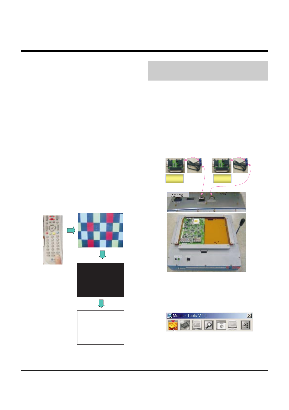
O Preliminary action is applied to the test for afterimage
discharge detection, and 100% FULL WHITE PATTERN
must be operated automatically.
O Test for afterimage discharge detection
1) After pressing Power Only key(only operating by
pressing Power Only key), Full Test Pattern(2 min
30sec) --> Full Black Pattern(30sec) --> After this state,
Full White Pattern is displayed.
(but you must preset the program for Full White State
when you press the Main Power Off/On)
2) Pattern Mode is deselected by pressing CH +/-, Exit Key.
[ Set is activated HEAT-RUN without signal generator in this
mode.
3. MICOM Download(Option)
3-1. Required Test Equipment
(1) JIG-LEVER TYPE for adjusting: 1EA
(2) PC & MONITOR: 2EA
(3) BOARD for INTERFACE: IIC & ISP BOARD: 2EA
(4) 15P D-SUB CABLE: 2EA
(5) Using the 12/15 line of D-SUB 15P
12-SDA/15-SCL
3-2. JIG Connection
3-3. Establishment Program
(1) Establish LGE Monitor Tools v1.1
(2) The program work and it is opened program window as
seen below.
Test Pattern 2min 30sec
Test Pattern 30sec
If you turn on a still screen more than 20 minutes (Especially
Digital pattern(13 CH), Cross Hatch Pattern), an afterimage
may occur in the black level part of the screen.
connection
to PC
connection
to PC
- 10 -
ADJUSTMENT INSTRUCTIONS
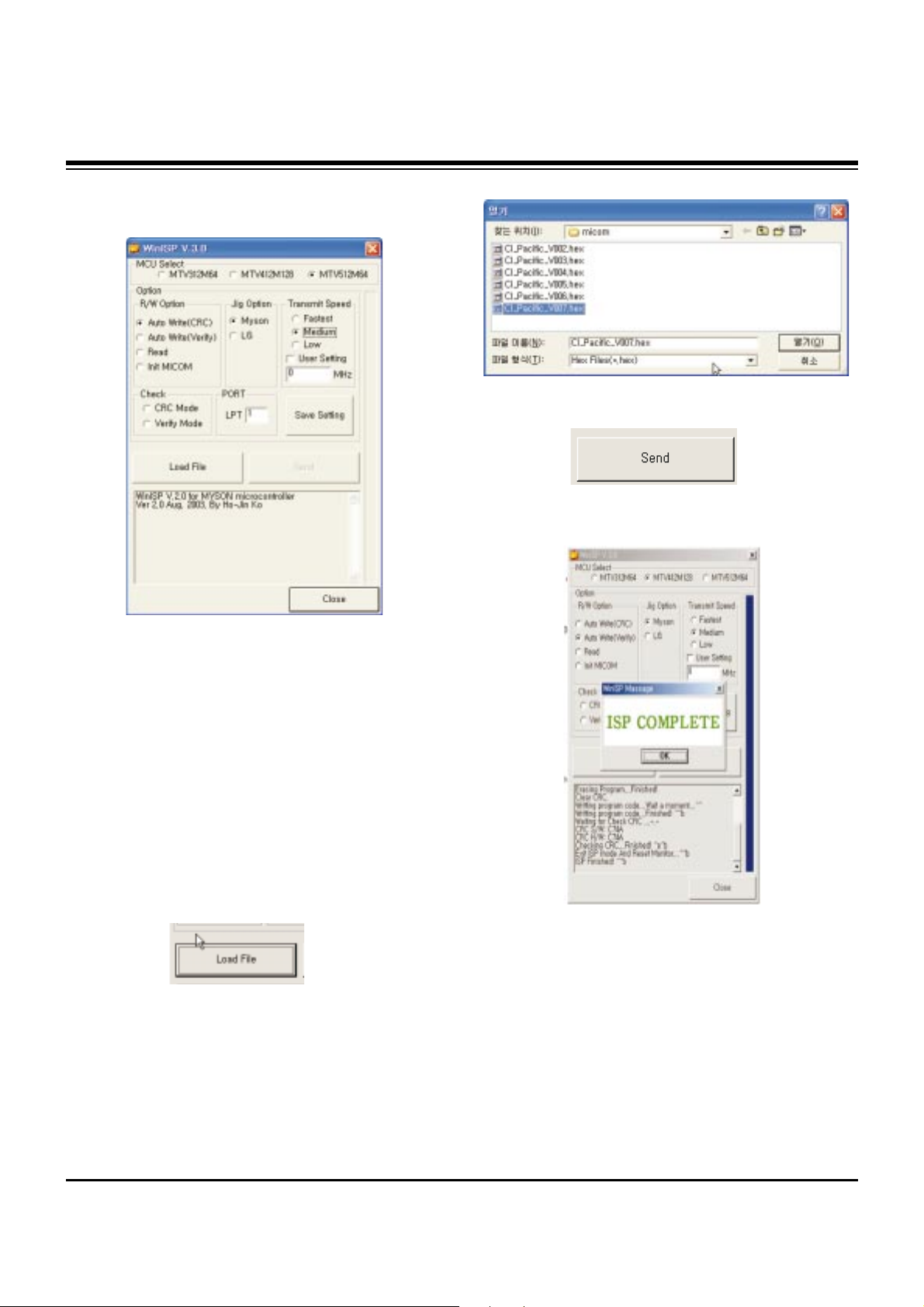
(3) Click the first icon shown in fig.9. The window seen in
fig.10 should appear.
3-4. Set Method
(1) MCU Select: MTV512M64
(2) Option
R/W Option: Auto Write(Verity)
Jig Option: Myson
Transmit Speed: Medium
(3) Check: Just do it with blank micom.
(4) PORT
Chose Parallel Port (normal LPT1)
Attention: You must chose EPP when select Rom BIAS at
LPT
3-5. Download Method
(1) Click the Load File.
(2) Locate and select the correct file from your computer.
(*.hex).
(3) Click the Send.
(4) When you see (ISP COMPLETE) the download is
complete.
- 11 -
ADJUSTMENT INSTRUCTIONS
4. ADC-Set Adjustment
4-1. Synopsis
ADC-Set adjustment to set the black level and the Gain to
optimum.
4-2. Test Equipment
Service R/C, 801GF(802V, 802F, 802R) or MSPG925FA
Pattern Generator
(480i/1080i The Horizontal 100% Color Bar Pattern adjust to
within 0.7±0.1Vp-p)
4-3. Adjustment
(1) Select Component1 as the input with 100% Horizontal
Color Bar Pattern(HozTV31Bar) in 480i Mode
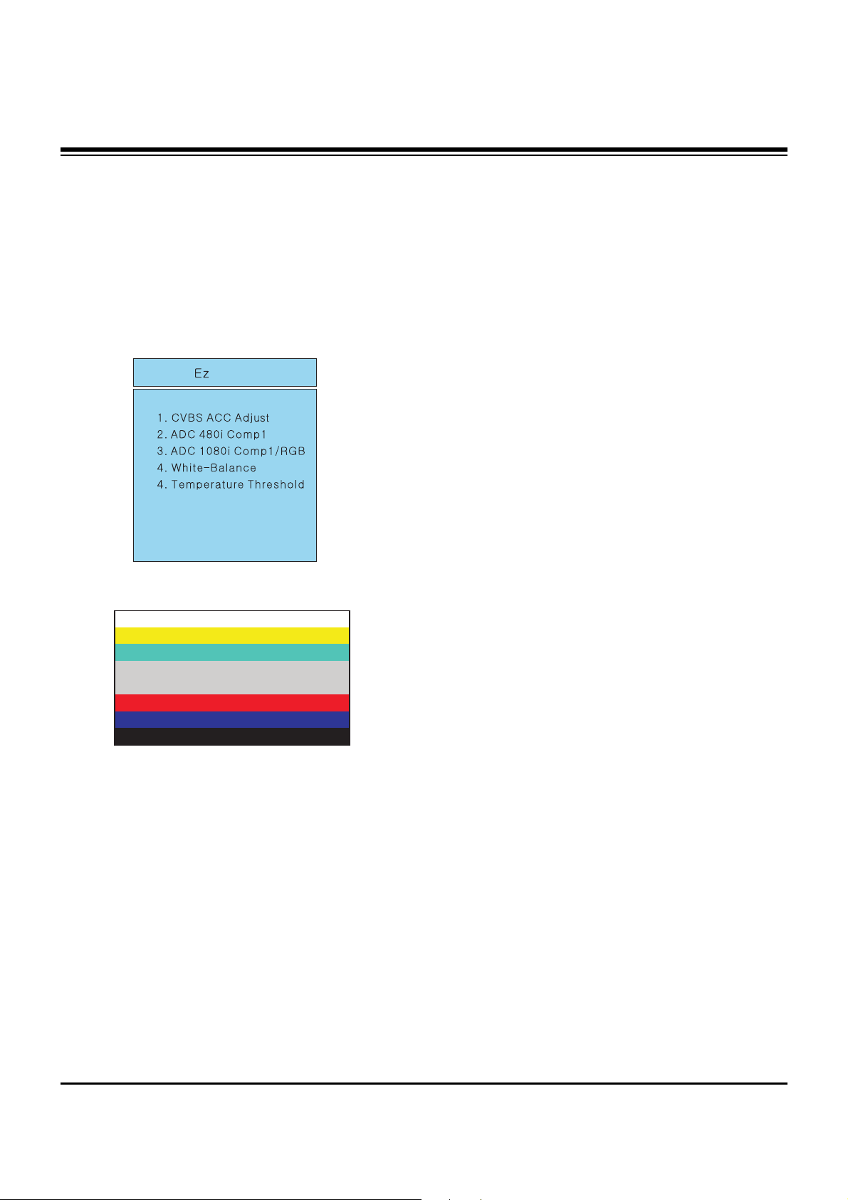
(2) After receiving signal for at least 1 second, press the ADJ
Key on the Service R/C to enter the ‘Ez - Adjust’ and select
the ‘2. ADC 480i Comp1’.
Pressing the Enter Key to adjust automatically.
(3) When the adjustment is over, 'MST3361 Component
Success’ is displayed. If the adjustment has errors,
'MST3361 Configuration Error’ is displayed.
(4) Select Component1 as the input with 100% Horizontal
Color Bar Pattern(HozTV31Bar) in 1080i Mode.
(5) After receiving signal for at least 1 second, press the ADJ
Key on the Service R/C to enter the ‘Ez - Adjust’ and select
the ‘3. ADC 1080i Comp1/RGB’.
Pressing the Enter Key to adjust automatically.
(6) When the adjustment is over, 'MST3361 Component
Success’ is displayed. If the adjustment has errors,
'MST3361 Configuration Error’ is displayed.
(7) After the Component MST3361 adjustment is over, convert
the RGB-DTV Mode and display Pattern.
When the adjustment is over, 'MST3361 RGB_DTV
Success’ is displayed.
(8) Readjust after confirming the case Pattern or adjustment
condition where the adjustment errors.
(9) After adjustment is complete, exit the adjustment mode by
pressing the ADJ KEY.
<Adjustment Mode>
<Adjustment Pattern: 480i/1080i 60Hz HozTV31Bar Pattern>
- 12 -
ADJUSTMENT INSTRUCTIONS
5. POWER PCB Assy Voltage
Adjustment
(Va, Vs Voltage Adjustment)
5-1. Test Equipment :D.M.M 1EA
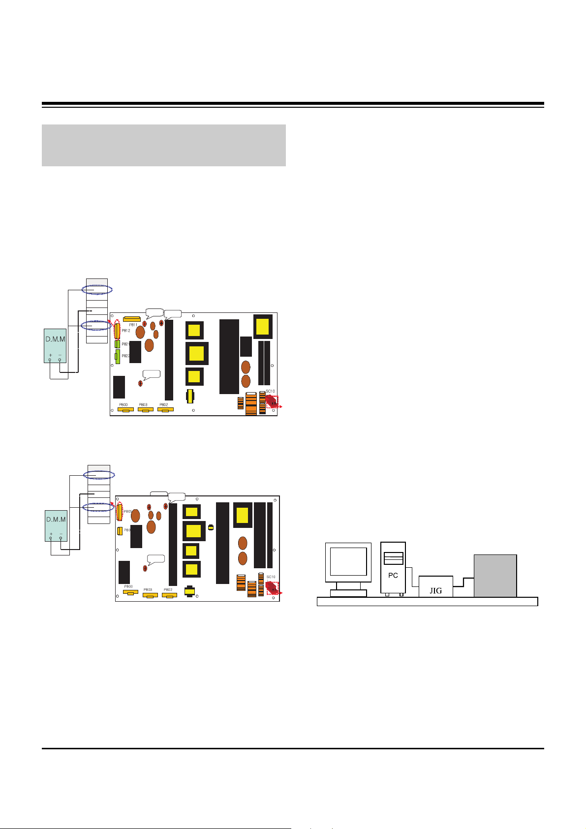
5-2. Connection Diagram for Measuring
Refer to Fig 1.
5-3. Adjustment
(1) Va Adjustment
1) Connect + terminal of D.M.M to Va pin of P812(50”:
P805) and connect – terminal to GND pin of P812(50”:
P805).
2) Adjust VR901 voltage to match that of the label on the
Top/Right of the panel. (Deviation : ±0.5V)
(2) Vs Adjustment
1) Connect + terminal of D.M.M to Vs pin of P812(50”:
P805) and connect – terminal to GND pin of P812(50”:
P805).
2) Adjust RV401 voltage to match that of the label on the
Top/Right of the panel. (Deviation : ±0.5V)
6. EDID(The Extended Display
Identification Data)/DDC
(Display Data Channel) Download
This is the function that enables “Plug and Play".
6-1. HDMI EDID Data Input
(1) Required Test Equipment
1) PC, Jig for adjusting DDC. (PC serial to D-sub
Connection equipment)
2) S/W for writing DDC(EDID data write & read)
3) D-Sub cable
4) Jig for HDMI Cable connection
(2) Preparation for Adjustments &
Setting of Device
1) Set devices as below and turn on the PC and JIG.
2) Open S/W for writing DDC (EDID data write & read).
(operated in DOS mode)
Each PCB Assy must be checked by Check JIG Set before
assembly. (Especially, be careful Power PCB Assy which can
cause Damage to the PDP Module.)
11 1
VsADJ
VR951
VaADJ
VR901
3.3VADJ
VR221
T8
01
T9
01
T1
12
T5
01
L6
01
5V
GND
Va
GND
GND
NC
Vs
Vs
P811
11 1
VsADJ
VR951
VsADJ
VR951
VaADJ
VR901
VaADJ
VR901
3.3VADJ
VR221
T8
01
T9
01
T1
12
T5
01
L6
01
5V
GND
Va
GND
GND
NC
Vs
Vs
P811
<Fig. 1-1> Connection Diagram of Power Adjustment for
Measuring (Power Board): 42” XGA
VsADJ
VR951
5V
GND
Va
GND
GND
NC
Vs
Vs
P811
111
VaADJ
VR901
3.3VADJ
VR221
T8
01
T9
01
L8
51
T5
01
T1
12
L6
01
VsADJ
VR951
5V
GND
Va
GND
GND
NC
Vs
Vs
P811
111
VaADJ
VR901
VaADJ
VR901
3.3VADJ
VR221
T8
01
T9
01
L8
51
T5
01
T1
12
L6
01
<Fig. 1-2> Connection Diagram of Power Adjustment for
Measuring (Power Board): 50”
PDP TV SET
(or Digital Board)
<Fig. 2>
 Loading...