

LG 50PC1RR Schematic

PLASMA TV
SERVICE MANUAL
CAUTION
BEFORE SERVICING THE CHASSIS,
READ THE SAFETY PRECAUTIONS IN THIS MANUAL.
CHASSIS : MF-056L
MODEL : 50PC1RR
50PC1RR-ZL
website:http://biz.LGservice.com
e-mail:http://www.LGEservice.com/techsup.html

- 2 -
CONTENTS
SAFETY PRECAUTIONS ....................................................................................3
DESCRIPTION OF CONTROLS ..........................................................................4
SPECIFICATIONS ................................................................................................9
ADJUSTMENT INSTRUCTIONS .......................................................................11
TROUBLE SHOOTING GUIDE..........................................................................18
BLOCK DIAGRAM.............................................................................................29
EXPLODED VIEW..............................................................................................32
EXPLODED VIEW PARTS LIST ........................................................................33
REPLACEMENT PARTS LIST...........................................................................34
SCHEMATIC DIAGRAM.........................................................................................
PRINTED CIRCUIT DIAGRAM ..............................................................................
- 3 -
SAFETY PRECAUTIONS
Many electrical and mechanical parts in this chassis have special safety-related characteristics. These parts are identified by in the
Schematic Diagram and Replacement Parts List.
It is essential that these special safety parts should be replaced with the same components as recommended in this manual to prevent
X-RADIATION, Shock, Fire, or other Hazards.
Do not modify the original design without permission of manufacturer.
General Guidance
An isolation Transformer should always be used during the
servicing of a receiver whose chassis is not isolated from the AC
power line. Use a transformer of adequate power rating as this
protects the technician from accidents resulting in personal injury
from electrical shocks.
It will also protect the receiver and it's components from being
damaged by accidental shorts of the circuitry that may be
inadvertently introduced during the service operation.
If any fuse (or Fusible Resistor) in this monitor is blown, replace it
with the specified.
When replacing a high wattage resistor (Oxide Metal Film Resistor,
over 1W), keep the resistor 10mm away from PCB.
Keep wires away from high voltage or high temperature parts.
Due to high vacuum and large surface area of picture tube,
extreme care should be used in handling the Picture Tube.
Do not lift the Picture tube by it's Neck.
Leakage Current Cold Check(Antenna Cold Check)
With the instrument AC plug removed from AC source, connect an
electrical jumper across the two AC plug prongs. Place the AC
switch in the on position, connect one lead of ohm-meter to the AC
plug prongs tied together and touch other ohm-meter lead in turn to
each exposed metallic parts such as antenna terminals, phone
jacks, etc.
If the exposed metallic part has a return path to the chassis, the
measured resistance should be between 1MΩ and 5.2MΩ.
When the exposed metal has no return path to the chassis the
reading must be infinite.
An other abnormality exists that must be corrected before the
receiver is returned to the customer.
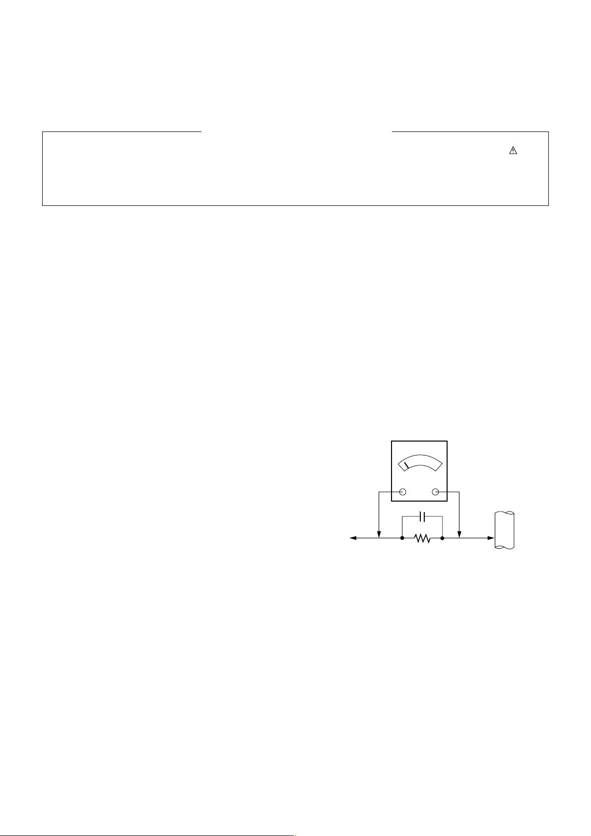
Leakage Current Hot Check
(See below Figure)
Plug the AC cord directly into the AC outlet.
Do not use a line Isolation Transformer during this check.
Connect 1.5K/10watt resistor in parallel with a 0.15uF capacitor
between a known good earth ground (Water Pipe, Conduit, etc.)
and the exposed metallic parts.
Measure the AC voltage across the resistor using AC voltmeter
with 1000 ohms/volt or more sensitivity.
Reverse plug the AC cord into the AC outlet and repeat AC voltage
measurements for each exposed metallic part. Any voltage
measured must not exceed 0.75 volt RMS which is corresponds to
0.5mA.
In case any measurement is out of the limits specified, there is
possibility of shock hazard and the set must be checked and
repaired before it is returned to the customer.
Leakage Current Hot Check circuit
1.5 Kohm/10W
To Instrument's
exposed
METALLIC PARTS
Good Earth Ground
such as WATER PIPE,
CONDUIT etc.
AC Volt-meter
IMPORTANT SAFETY NOTICE
0.15uF
- 4 -
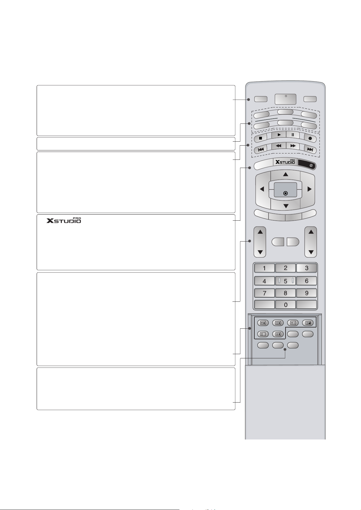
DESCRIPTION OF CONTROLS
MODE
INPUT
TV
DVD
V
C
R
A
U
D
IO
P
IP
P
R
-
P
IP
P
R
+
S
W
A
P
PIP INPUT
S
T
B
M
E
N
U
MUTE
SIZE POSITION INDEX
FAV
SLEEP
I/II
PIP ARC
Q.VIEWLIST
TEXT
OK
VOL PR
MULTIMEDIA
POWER
CABLE
HOLD
REVEAL
?
TIME
MARK
E
XIT
L
IV
E
T
V
TIME
SHIFT
TIME
SHIFT
POWER
INPUT
MULTIMEDIA
MODE
VCR BUT-
TONS
MARK
LIVE TV
MENU
EXIT
VOL
DD/ EE
(Volume
Up/Down)
PR
DD/ EE
(Programme
Up/Down)
MUTE
TEXT
ARC
I/II
switches the set on from standby or off to standby.
Selects the TV, AV, Component, RGB or HDMI/DVI
modes.
switches the set on from standby.
Selects the Component, RGB or HDMI/DVI modes.
switches the set on from standby.
Selects another device.
Controls a video cassette recorder.
These buttons are used for X Studio.
For further details, see the ‘X Studio’ section.
Selects the wanted functions.
In AV1, AV2, S-Video2, AV3, AV4, Component, RGB,
HDMI/DVI input sources, screen returns to the last
TV programme.
Brings up the HOME menu.
Displays on screen menus one by one.
Exits the current menu.
Memorizes menu changes.
Clears all on-screen displays and returns to TV
viewing from any menu.
Increases/decreases sound level.
Select a programme.
Switchs the set on from standby.
Switches the sound on or off.
These buttons are used for teletext.
For further details, see the ‘Teletext’ section.
Note : In teletext mode, the PIP PR +/-, SWAP and
PIP INPUT buttons are used for teletext function.
Changes the picture format.
Selects the language during dual language broadcast.
Selects the sound output.
- 5 -
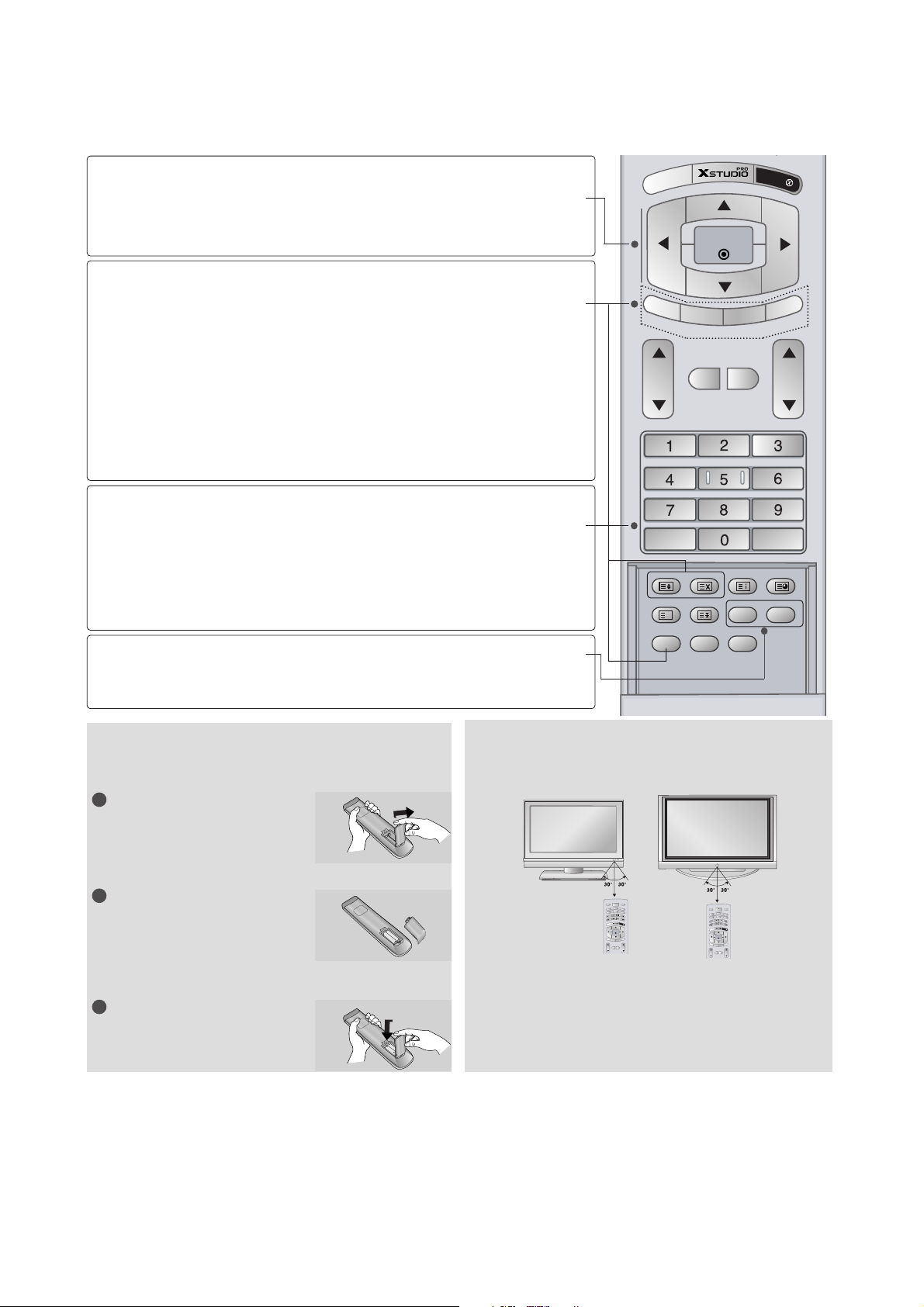
Installing Batteries
V
Use a remote control 7 meter distance and 30
degree (left/right)within the receiving unit scope.
V
Dispose of used batteries in a recyclebin to pre-
serve environment.
Remote control effective range
P
IP
P
R
-
P
IP
P
R
+
S
W
A
P
PIP INPUT
M
E
N
U
MUTE
SIZE POSITION INDEX
SLEEP
FAV
I/II
PIP ARC
Q.VIEWLIST
TEXT
OK
VOL PR
HOLD
REVEAL
?
TIME
E
XIT
IVE TV
TIME
SHIFT
TIME
SHIFT
OK
DD/ EE
or
FF/ GG
(TIME SHIFT)
PIP
PIP PR +/-
SWAP
PIP INPUT
SIZE
POSITION
NUMBER buttons
LIST
Q.VIEW
SLEEP
FAV
accepts your selection or displays the
current mode.
Adjusts menu settings.
Selects menu item.
Switches the sub picture on or off.
Selects PIP , POP or DW modes.
Selects a programme for the sub picture.
Alternates between main and sub picture.
Selects the input mode for the sub picture.
Adjusts the sub picture size.
Moves the sub picture to
DD/ EE
or FF/ GGdirection.
Selects a programme.
Selects numbered items in a menu.
Switchs the set on from standby.
Displays the programme table.
Returns to the previously viewed programme.
Sets the sleep timer.
Selects a favourite programme.
Open the battery compartment cover on the back
side.
Insert two batteries in correct polarity (+ with +, - with
-). Don’t mix old or used batteries with new ones.
Close the cover.
1
2
3
MULTIMEDIA
INPUT
POWER
DVD
V
C
R
V
T
MODE
CABLE
S
O
I
T
D
B
U
A
M
A
R
K
L
I
V
E
T
V
E
X
U
I
N
T
E
M
OK
TIME
TIME
SHIFT
SHIFT
P
T
I
P
U
P
P
R
N
I
-
P
I
P
P
I
P
P
P
R
A
+
W
S
MUTE
TEXT
VOL PR
INPUT
V
T
O
I
D
U
A
U
N
E
M
TIME
SHIFT
P
I
P
P
R
-
P
I
P
MUTE
VOL PR
MULTIMEDIA
POWER
DVD
V
C
R
MODE
CABLE
S
T
B
M
A
R
K
L
I
V
E
T
V
E
X
I
T
OK
TIME
SHIFT
T
U
P
N
I
P
I
P
P
P
R
A
+
W
S
TEXT
- 6 -
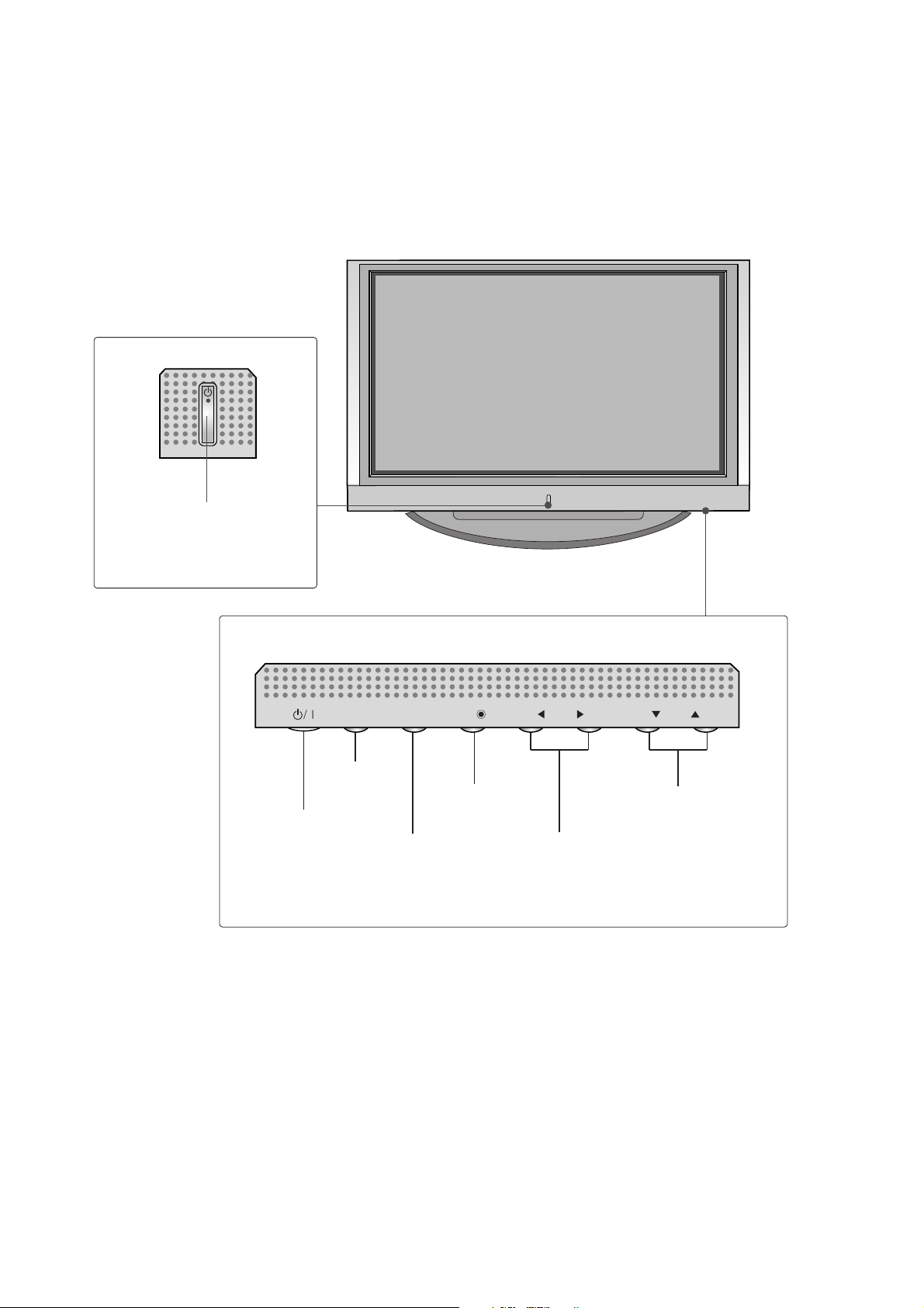
Front Panel Controls
PROGRAMME Buttons
VOLUME Buttons
MENU Button
OK Button
INPUT Button
POWER Button
PR
VOL
OK
MENU
INPUT
Power/Standby Indicator
• illuminates red in standby
mode.
• illuminates white when the set
is switched on.
PR
VOL
OK
MENU
INPUT

- 7 -
HDMI/DVI Input
Connect a HDMI signal to HDMI/DVI.
RGB/Audio Input
Connect the monitor output from a PC/DTV
to the appropriate input port.
Component Input
Connect a component video/audio device to
these jacks.
Power Cord Socket
This set operates on an AC power. The voltage
is indicated on the Specifications page. Never
attempt to operate the set on DC power.
Euro Scart Socket (AV1/AV2)
Connect scart socket input or output from an
external device to these jacks.
Antenna Input
RS-232C Input
(CONTROL&SERVICE)
Port
Connect the serial port of the control devices
to the RS-232C jack.
Remote Control Port
S-Video Input
Connect S-Video out from an S-VIDEO device.
Audio/Video Input
Connect audio/video output from an external
device to these jacks.
Variable Audio Output
Connect an external amplifier or add a subwoofer to your surround sound system.
1
2
3
4
5
6
7
8
9
10
11
ANTENNA
IN
AV 1
AV 2
AUDIO OUT
VARIABLEARIABLE
RGB IN
COMPONENT IN
VIDEOVIDEO
AUDIO
AV IN 4
L/MONO
R
AUDIOAUDIO
VIDEOVIDEO
MONO
( )
AUDIO
VIDEO
S-VIDEO
AV IN 3
RGB
(PC/DTV)
AUDIO
(RGB/DVI)
CONTROL IN
REMOTE
S-VIDEOS-VIDEO
AC IN
HDMI/
DVI IN
RS-232C IN
(CONTROL
& SERVICE)
Back Connection Panel
S-VIDEO Input
Connect S-Video out from an SVIDEO device.
AUDIO Input
Connections are available for listening stereo sound from an
external device.
VIDEO Input
Connects the video signal from a
video device.
4
11
9
8
7
10
3
21
5
6
- 8 -
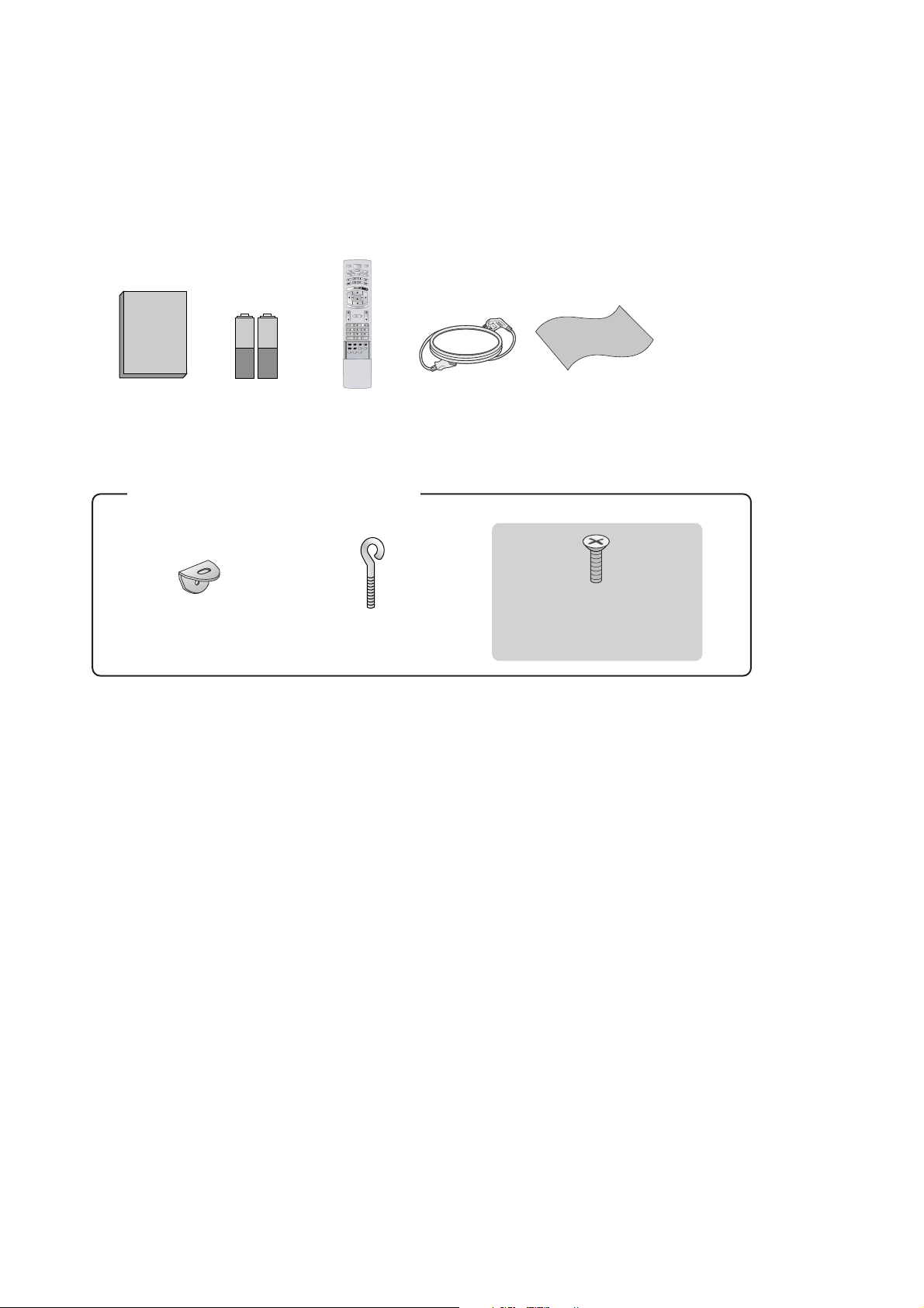
ACCESSORIES
2-Wall brackets
2-eye-bolts
For 42PC1RR
*,
50PC1RR
*
2-bolts for stand assembly
This feature is not available
for all models.
Owner's Manual
Owner’s Manual Batteries
MODE
INPUT
T
V
DVD
V
C
R
A
U
D
I
O
P
I
P
P
R
-
P
I
P
P
R
+
S
W
A
P
PI
P
I
N
P
U
T
S
T
B
M
E
N
U
MUTE
SIZE POSITION INDEX
SLEEP
FAV
I/II
PIP ARC
Q.VIEWLIST
TEXT
OK
VOL PR
MULTIMEDIA
POWER
CABLE
HOLD
REVEAL
?
TIME
E
X
I
T
M
A
R
K
L
I
V
E
T
V
TIME
SHIFT
TIME
SHIFT
Remote Control Power Cord Polishing Cloth
Polish the screen with the cloth
(Option)
Slightly wipe stained spot on
the exterior only with the
cleansing cloths for the product exterior if there is stain or
fingerprint on surface of the
exterior.
Do not wipe roughly when
removing stain. Please be
cautious of that excessive
power may cause scratch or
discoloration.

- 9 -
SPECIFICATIONS
NOTE : Specifications and others are subject to change without notice for improvement
.
V Application Range
This spec is applied to the 50” PLASMA TV used MF-056L Chassis.
V Specification
Each part is tested as below without special appointment.
1) Temperature : 25±5°C (77±9°F), CST : 40±5
2) Relative Humidity: 65±10%
3) Power Voltage: Standard Input voltage (100-240V~, 50/60Hz)
* Standard Voltage of each product is marked by models.
4) Specification and performance of each parts are followed each drawing and specification by part number in accordance with SBOM.
5) The receiver must be operated for about 20 minutes prior to the adjustment.
V Test Method
1) Performance : LGE TV test method followed.
2) Demanded other specification
Safety : CE, IEC specification
EMC : CE, IEC
V General Specification
1. Module Specification( 50”WXGA MODULE )
Chassis
MF-056L 50PC1RR-ZL EU LG
Model Name Market Brand Remark
50PC1RR-ZL Safety : IEC/EN60065, EMI : EN55013, EMS : EN55020
TEST
EU
Model Appliance
Remark
Market
Display Screen Device
Aspect Ratio
PDP Module
Operating Environment
Storage Environment
Input Voltage
1
2
3
4
5
6
No Item Specification Remark
50” Wide Color Display Module
16:9
PDP50X3,
RGB Closed Type
1)Temp. : 0~40deg
2)Humidity : 0~85%
3)Temp. : -20~60deg
4)Humidity : 0~85%
100-240V~, 50/60Hz
Plasma Display Panel
Glass Filter
LGE SPEC.
Maker : Sanken
- 10 -
2. Model General Specification
Market
Broadcasting system
Available Channel
Receiving system
Video Input (2EA)
Video Output (1EA)
S-Video Input (2EA)
Component Input (1EA)
RGB Input (1EA)
HDMI Input (1EA)
Audio Input (4EA)
Wired Control (1EA)
Audio variable out (1EA)
1
2
3
4
5
6
7
8
9
10
11
12
13
No Item Specification Remark
EU
PAL-BG/I/DK, NTSC
BAND PAL NTSC
VHF/UHF C1~C69 2~83
CATV S1~S47 1~71
Upper Heterodyne
PAL, SECAM, NTSC
PAL, SECAM, NTSC
PAL, SECAM, NTSC
Y/Cb/Cr, Y/Pb/Pr
RGB-PC,
RGB-DTV
HDMI-PC
HDMI-DTV
PC Audio, Component(1EA), AV (2EA)
4 System : PAL, SECAM, NTSC, PAL60
4 System : PAL, SECAM, NTSC, PAL60
4 System : PAL, SECAM, NTSC, PAL60
Compatible with DVI
L/R Input
Available for TV Speaker Off
- 11 -
ADJUSTMENT INSTRUCTIONS
1. Application Object
These instructions is applied all of the 50” PLASMA TV,
MF-056L Chassis.
2. Note
(1) Because this is not a hot chassis, it is not necessary to use
an isolation transformer. However, the use of isolation
transformer will help protect test instrument.
(2) Adjustment must be done in the correct order.
(3) The adjustment must be performed in the circumstance of
25±5°C of temperature and 65±10% of relative humidity if
there is no specific designation.
(4) The input voltage of the receiver must keep 100-220V~,
50/60Hz.
(5) The receiver must be operated for about 15 minutes prior
to the adjustment.
O After RGB Full white HEAT-RUN Mode, the receiver must
be operated prior to adjustment.
O Enter into HEAT-RUN MODE
1) Press the POWER ON KEY on R/C for adjustment.
2) OSD display and screen display PATTERN MODE.
[ Set is activated HEAT-RUN without signal generator in
this mode.
[ Single color pattern(RED/BLUE/GREEN) of HEAT-RUN
mode uses to check PANEL.
Caution) If you turn on a still screen more than 20 minutes,
(Especially digital pattern, cross hatch pattern) after
image may be occur in the black level part of the screen.
3. Channel memory
3-1. Setting up the LGIDS
1) Install the LGIDS. (idsinst.exe)
2) After installation, restart your PC.
3) Extract [files.zip] to folder [c:\LGIDS\files].
4) Start LGIDS.
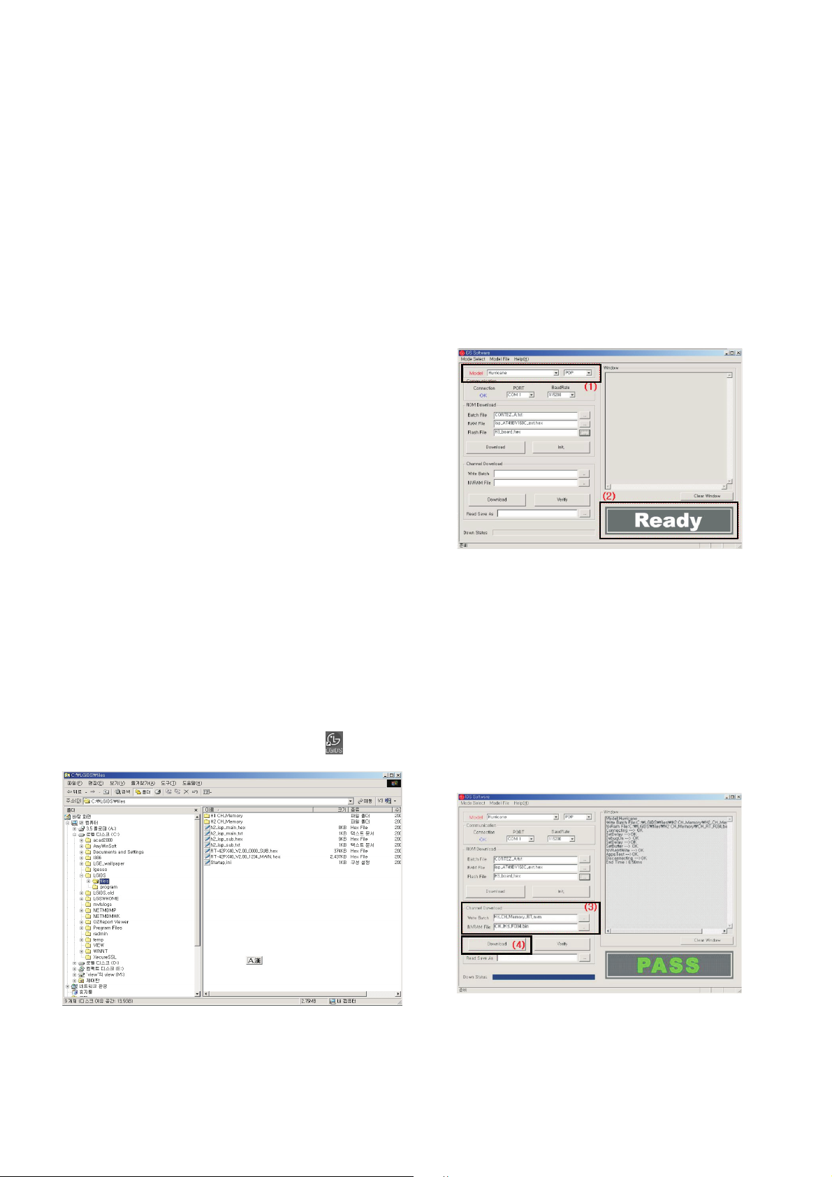
3-2. Channel memory Method
1) Select “PDP” and “Hurricane” on Model dialog. And check
your connection in Communication dialog. (If your
connection is ‘NG’, then set your PORT.(COM1,2,3,...)
correctly.)
2) Connect RS-232C cable and turn on the power.( Use the
general RS-232C Serial Cable)
(If your connection has completed, you can see “Ready”.)
[ If your set is not an end products but only a board, you
have to make your board to Stand-by state (LED_R). And
you have to Download in Stand_by power state.
3) Select proper CH_memory file(*.nvm) for each model at
[NVRAM Download] $ [Write Batch]
Next, select proper binary file(*.bin) including the CH
information for each model at [NVRAM File].
File name : H2_CH_Memory_RZ.nvm
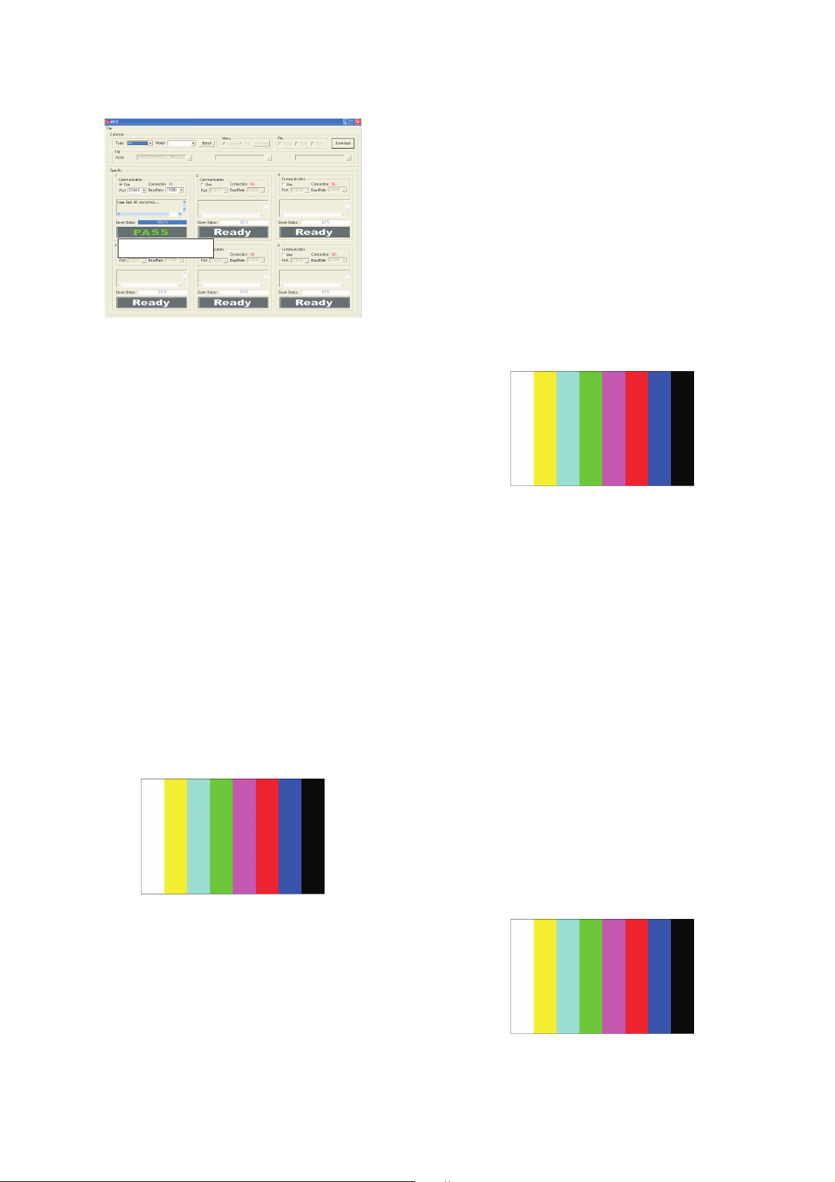
4) Click the [Download] button.
It means the completion of the CH memory download if all
items show ‘OK’ and Status is changed by ‘PASS’ at the
lower right corner of the window.
5) If you want to check whether the CH information is
memorized correctly or not, click the [Verify] button.
And then compare NVRAM File(*.bin) with the CH
information downloaded.
(Fig. 1)
(Fig. 2)
(1)
(2)(2)
(4)
(3)
(Fig. 3)
- 12 -
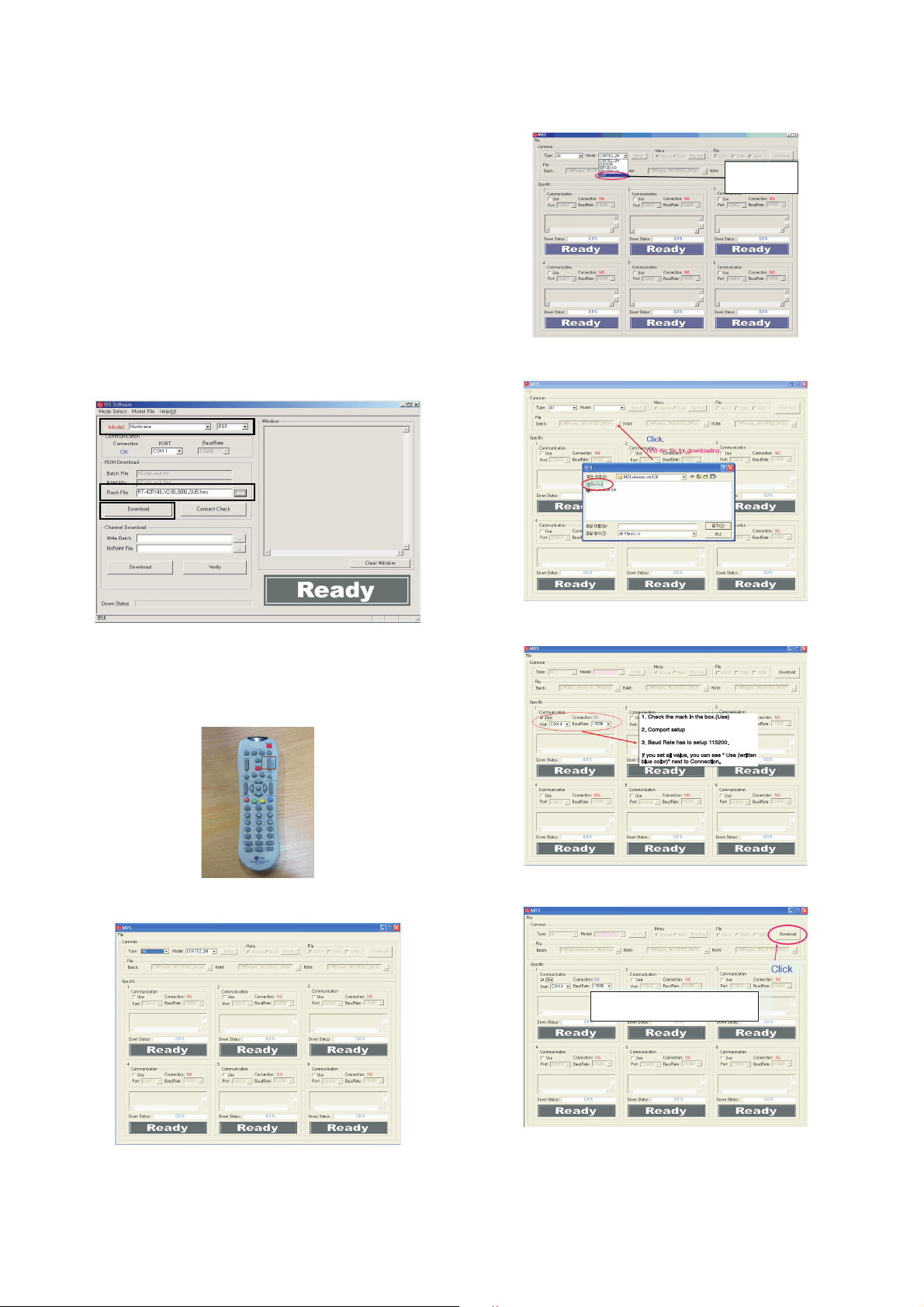
4. Sub Program Down Load
4-1. Sub Program Down Load for “Cortez”
1) Select “PDP” and “Hurricane” on Model dialog. and check
your connection in Communication dialog.
(If your connection is ‘NG’, then set your PORT(COM1,2,3,...)
correctly)
2) Connect RS232 cable and turn on the power.(Use the
Special Cable For Sub-program)
(If your connection has completed, you can see )
3) Select proper ‘Model’ for each model.
4) Select ‘flash file’ for each model.
5) Click the [Download] button.
It means the completion of the ROM download if all items
show ‘OK’ and Status is changed by ‘PASS’ at the lower
right corner of the window.
4-2. Sub Program Down Load for “DVR”
1) Download Setup
- You must change the DVR Download mode by using the
Turbo Sound Key on the remote controller.
2) MDS Program Setup
- Open the MDS Program
(1)
(2)
(3)
You have to
select this item.select this item.
Click.
Find the file for downloadingFind the file for downloading
DVR
DVR
You can’t remove the power
cable while downloading
DVR
(Fig. 4)
- 13 -
5. Auto AV(CVBS) Color Balance
5-1. Requirement
O This AV color balance adjustment should be performed
before White Balance Adjustment.
O
It is very import to use correct adjustment pattern like (Fig.5).
A Within the pattern, color sequence should be aligned :
W-Y-C-G-M-R-BLUE-BLACK.
(If color sequence is reversed (Black ->...-> White),
reverse the pattern with REV key, when using Master
pattern generator like MSPG-925)
A If Minimum Black Level and/or Maximum White Level is
not correct, Do select 100% Color Bar Pattern.
5-2. Required Test Equipment
1) Remote controller for adjustment
2) AV Pattern Generator : 802F Pattern Generator,
Master(MSPG-925FA), etc.
(Which has PAL Composite Video format output with
standard(1.0 Vpp) Vertical 100% Color Bar Pattern as Fig. 5)
5-3. Method of Auto RGB Color Balance
1) Input the PAL Composite Video (Fig.5. 100% Color Bar
Pattern) into video input. ( 50PC1RR-ZL : AV3/AV4 )
2) Set the PSM to Dynamic mode in Picture menu.
3) Press INSTART key on R/C for adjustment.
4) Press the
G (Vol.+) key operate to set , then it becomes
automatically.
5) Auto-RGB OK means completed adjustment.
6. Auto Component Color Balance
6-1. Requirement
O
It is very import to use correct adjustment pattern like (Fig.6).
A Within the pattern, color sequence should be aligned :
W-Y-C-G-M-R-BLUE-BLACK.
(If color sequence is reversed (Black ->...-> White),
reverse the pattern with REV key, when using Master
pattern generator like MSPG-925)
A If Minimum Black Level and/or Maximum White Level is
not correct, Do select 100% Color Bar Pattern.
6-2. Required Test Equipment
1) Remote controller for adjustment.
2) 802F Pattern Generator.
( Which has 720p YpbPr output with Standard(0.7Vpp)Vertical
100% Color Bar Pattern as Fig. 6 )
6-3. Method of Auto RGB Color Balance
1) Input the Component 720p 100% Color Bar signal into
Component1 or Component2.
2) Set the PSM to Dynamic mode in Picture menu.
3) Press INSTART key on R/C for adjustment.
4) Press the
G (Vol.+) key operate To set , then it becomes
automatically.
5) Auto-RGB OK means completed adjustment.
7. Auto RGB Color Balance
7-1. Requirement
O
It is very import to use correct adjustment pattern like (Fig. 7).
A Within the pattern, color sequence should be aligned :
W-Y-C-G-M-R-BLUE-BLACK.
(If color sequence is reversed (Black ->...-> White),
reverse the pattern with REV key, when using Master
pattern generator like MSPG-925)
A If Minimum Black Level and/or Maximum White Level is
not correct, Do select 100% Color Bar Pattern.
7-2. Required Test Equipment
1) Remote controller for adjustment
2) 802F Pattern Generator, Master (MSPG-925FA), etc.
( Which has XGA 60Hz PC Format output with
standard(0.7Vpp) 100 % Color Bar Pattern as Fig. 7 )
7-3. Method of Auto RGB Color Balance
1) Input the PC 1024x768 @ 60Hz 100 % Color Bar Pattern
into RGB.
2) Set the PSM to Dynamic mode in Picture menu.
3) Press INSTART key on R/C for adjustment.
4) Press the
G (Vol.+) key operate To set , then it becomes
automatically.
5) Auto-RGB OK means completed adjustment.
(Fig. 5) Auto AV(CVBS) Color Balance Test Pattern
(Fig. 6) Auto Component Color Balance Test Pattern
Turn power off and than
turn on.(Main AC Power)
DVR
(Fig. 7) Auto RGB Color Balance Test Pattern

- 14 -
8. Checking DVR Function and HDD
8-1. Time Shift
1) Press ‘OK’ button and check Time Shift is working through
Progress bar is on.
2) Press after the time is 0:00:02 on the bar and check
previous picture for a few seconds.
( just , is working under 30seconds)
3) Press and check a live picture back.
8-2. Recoding
1) Time setting :
(1) Set any time on the MENU for recoding.
(Recoding can’t be done under the Time is not active.
When main power is off , the time will be resetted.)
2) Manual Recoding :
(1)
Set recoding information and check it on the scheduled
list.
3) Instant Recoding.
(1) Press the recoding button on remote control and record
a present program for 10 seconds then press the stop
button to stop recoding.
(2) After finishing recoding, play the recoded clip on ’the
Recoded TV’.
(Fig. 8) DVR MENU
(Fig. 9) Time Shift Progress bar
(Fig. 10) DVR MENU
(Fig. 11) Scheduled List
(Fig. 12) Xstudio PRO MENU
(Fig. 13) Recoded List

- 15 -
9. POWER PCB Assy Voltage
Adjustments (Va, Vs Voltage adjustments)
9-1. Test Equipment : D.M.M. 1EA
9-2. Connection Diagram for Measuring
: refer to Fig.14
9-3. Adjustment Method
(1) Va Adjustment
1) After receiving 100% Full White Pattern, HEAT RUN.
2) Connect + terminal of D. M..M. to Va pin of P807, connect
-terminal to GND pin of P807.
3)
After turning RV501,voltage of D.M.M adjustment as
same as Va voltage which on label of panel right/top.
(deviation;
±
0.5V)
(2) Vs Adjustment
1) Connect + terminal of D. M..M. to Vs pin of P807, connect
-terminal to GND pin of P807.
2)
After turning RV 401, voltage of D.M.M adjustment as
same as Vs voltage which on label of panel right/top.
(deviation ;
±0.5V)
10. EDID (The Extended Display
Identification Data)/ DDC (Display
Data Channel) download
10-1. Required Test Equipment
1) Adjusting PC with S/W for writing EDID Data.
(S/W : EDID TESTER Ver.2.5)
2) A Jig for EDID Download.
3) Cable : Serial(9Pin or USB) to D-sub 15Pin cable, D-sub
15Pin cable, DVI to HDMI cable.
10-2. Setting of device
10-3. Preparation for Adjustment
1) As above Fig. 6, Connect the Set, EDID Download Jig, PC
& Cable.
2) Turn on the PC & EDID Download Jig. And Execute the
S/W : EDID TESTER Ver,2.5.
3) Set up S/W option.
Repeat Number : 5
Device Address : A0
PageByte : 8
4) Power on the Set.
10-4. Sequence of Adjustment
(1) DDC data of Analog-RGB
1) Init the data.
2) Load the EDID data.(Open File).
[Analog
(
RGB)
:
50PC1RR_RGB(3D)0307.ana]
(VGA,XGA)
[Digital(HDMI):
50PC1RR_HDMI(6537)_0307.div] (XGA)
3) Set the S/W as below.
4) Push the “Write Data & Verify”button. And confirm “Yes”.
5) If the writing is finished, you will see the “OK” message.
AC INPUT
(Fig. 14) Connection Diagram of power adjustment for measuring.
(Fig. 15) Connection Diagram of DDC download
Open File
- 16 -
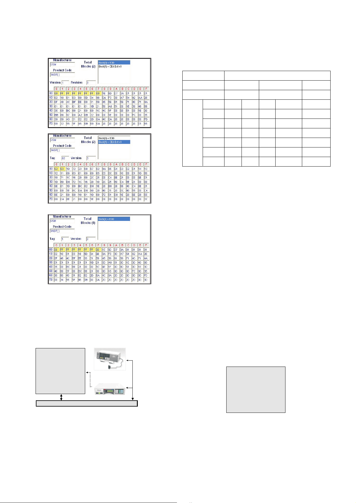
6) HDMI/DVI EDID data(check sum : 6537)
7) RGB EDID data(check sum : 3D)
11. Adjustment of White Balance
11-1. Required Equipment
1) Remote controller for adjustment.
2) Color Analyzer.(CA-100 or same product)
3) Auto W/B adjustment instrument.(only for Auto adjustment)
4) AV Pattern Generator.
11-2. Connecting diagram of equipment for
measuring (For Auto Adjustment)
W Auto adjustment Map(RS-232C)
11-3. Adjustment of White Balance
(For Manual adjustment)
O Operate the zero-calibration of the CA-100, then stick
sensor to PDP module surface when you adjust.
O For manual adjustment, it is also possible by the following
sequence.
1) Select white pattern of heat-run mode by pressing power
on key on remote control for adjustment then operate heat
run more than 15 minutes.
2) As below Fig.17, Supply 216Level (85 IRE) full screen
pattern to Video input.
(50PC1RR-ZL : AV3/AV4, Press the Front AV key->AV4)
3) Press the TV/AV KEY on R/C for converting input mode.
4) Set the PSM to Standard mode in Picture menu.
5) Enter the White Balance adjustment mode by pressing the
IN-START key twice(White Balance) on R/C.
6) Stick sensor to center of the screen and select each items
(Red/Green/Blue Gain and Offset) using D/E(CH +/-) key on R/C.
7) Adjust Only High Light with R Gain/ B Gain using F/G
(VOL+/-) key on R/C.
8) Adjust it until color coordination becomes as below.
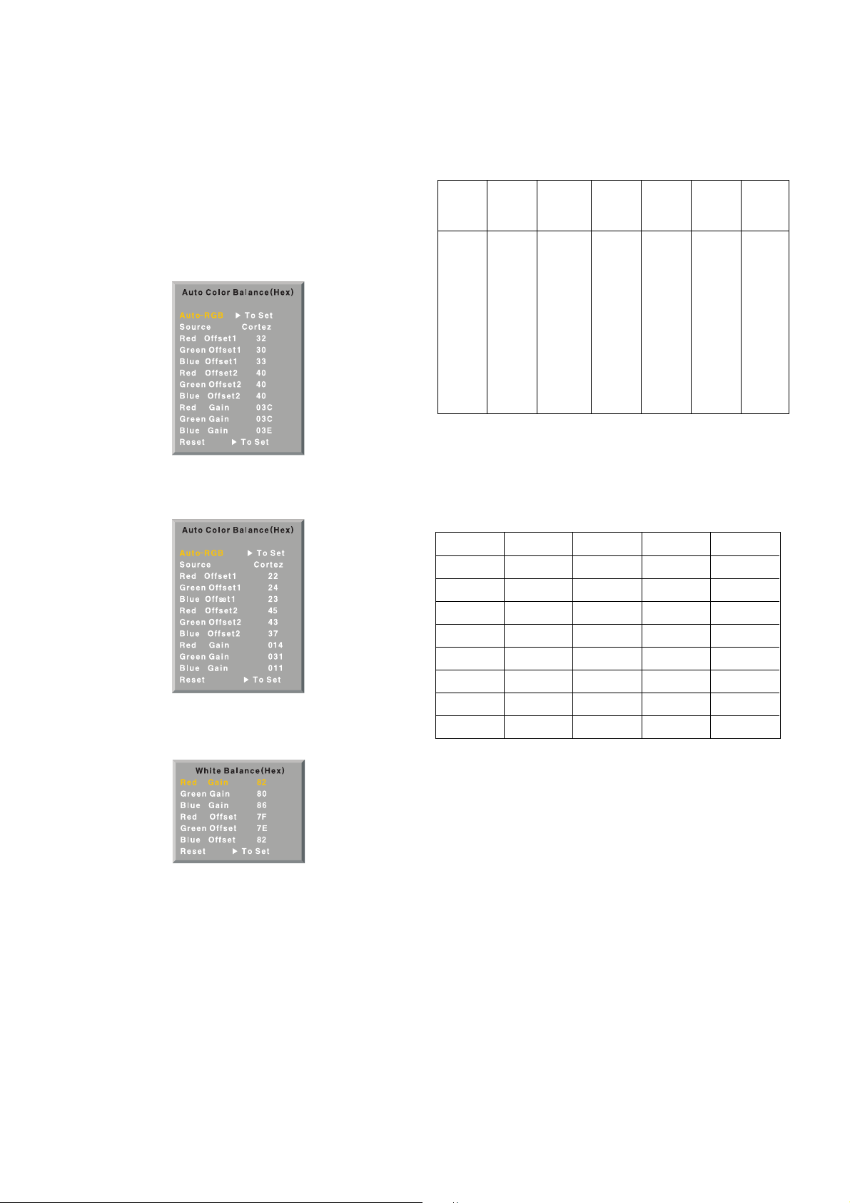
(Initially, R/G/B gain and R/G/B offset values are fixed as below
Red Gain : 82, Green Gain : 80, Blue Gain : 86
Red Offset : 7F, Green Offset : 7E, Blue Offset : 82)
Brightness : High Light : 80 ± 20cd/m2
Color-Coordinate : High Light : X : 0.285 ± 0.003
Y : 0.290 ± 0.003
Color Temperature : 9,300°K ± 500°K
9) When adjustment is completed, Exit adjustment mode
using EXIT key on R/C.
MSPG-
MSTG-5200
216 Level (85 IRE)
COLOR ANALYZER
TYPE ; CA-100
CVBS
signal
input
RS-232C Serial Communication
925
Pattern GeneratorPattern Generator
/
(Fig. 16) Connection Diagram of Auto W/B Adjustment
Type
Baud Rate
115200
Index
R Gain
G Gain
B Gain
R Offset
G Offset
B Offset
Data bit
8
Cmd1 Cmd2
ja
jb
jc
jd
je
jf
Stop bit
1
Parity
NONE
MF-056L
Protocol
Setting
Data Min Value
00(00)
00(00)
00(00)
00(00)
00(00)
00(00)
Max Value
255(FF)
255(FF)
255(FF)
255(FF)
255(FF)
255(FF)
(Fig. 17) Pattern for Adjustment of White Balance
216 Level (85 IRE)216 Level (85 IRE)
- 17 -
12. Input the Shipping Option Data
1) Push the ADJ key in a Adjust Remocon.
2) Input the Option Number that was specified in the BOM, into
the Shipping area.
3) The work is finished, Push
V Key.
13. Default value in adjustment mode
13-1. Auto Color Balance (AV)
13-2. Auto Color Balance (Component/RGB)
13-3. White Balance
14. Language Group
- Only EU 5 language support DVR functions. So Group ‘EUall’ and ‘EU-5’ have same languages.
15. Teletext Language Group
- It is not active when ‘EU-All’ is selected on language group.
- Then all teletext Language can be choose on user’s menu.
This is the default.
(Fig. 18) Default Value on OSD
(Fig. 19) Default Value on OSD
(Fig. 20) Default Value on OSD
5- Non-
EU etc
English
France
German
Spain
Italy
4- Non-
EU
English
France
German
Spain
Italy
3- EU-
East
English
France
German
Spain
Italy
2- EU-
North
English
France
German
Spain
Italy
1-EU-8
English
France
German
Spain
Italy
0- EU5
English
France
German
Spain
Italy
EU-All
English
France
German
Spain
Italy
0
English
German
Swedish
Italian
French
Spanish
Turkish
Greek
1
Polish
German
Estonian
Lettish
French
Serbocroat
Czech
Rumanian
2
English
German
Estonian
Lettish
Cyrillic2
Cyrillic3
Czech
English
3
English
German
Swedish
Italian
French
Hebrew
Turkish
Arabic
4
English
German
Swedish
Italian
French
Hebrew
Turkish
Farsi
- 18 -
TROUBLE SHOOTING GUIDE
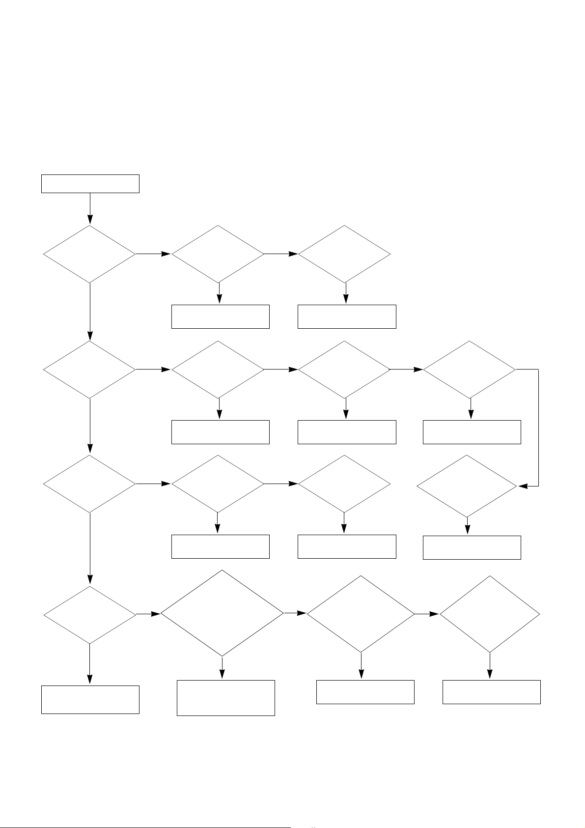
1. Power Board
1-1. The whole flowchart which it follows in voltage output state
Start check
Manufacture enterprise
meaning of a passage
1. Check the Power Off
condition.
Doesn't the
screen whole come
out?
Is it identical
with Power Off
condition?
Yes
Yes
No
No
No
No
No
2. Check the Interface
signal condition.
Is the Interface
signal operated?
Yes
3. Check the St-by 5V
signal circuit.
Doesn't the
low pressure output
come out?
Doesn't the
St-by 5V signal
come out?
Yes
Yes
No
4. Check the 5V Monitor
signal circuit.
Doesn't the
5V Monitor signal
come out?
Yes
7. Check the VSC Vs-ON
signal
Doesn't the
high tension output
come out?
Doesn't the
VSC signal Vs-ON
come out?
Yes
Yes
Does
high tension
output voltage Drop
occur?
When the
Y B/D Module
input connector is
removed, does output
voltage drop
occur?
When the
Y, Z B/D Module
input connector is remove,
does Power Board hightension
output voltage Drop
occur?
Yes No No
9. Check the Power
Board Output high
tension circuit
Yes
10. Check the Z B/D
Module output circuit
Yes
When the
Z B/D Module
input connector is
removed, does output
voltage Drop
occurs?
11. Check the Y B/D
Module output circuit
Yes
No
8. Check the Vs, Va
voltage output circuit.
Doesn't the
Vs, Va voltage output
come out?
Yes
No
No
5. Check the VSC RL-ON
signal.
Doesn't the
VSC signal RL-ON
come out?
Yes
6. Check the VSC low
pressure output
Doesn't the
VSC low pressure
output come out?
Yes

- 19 -
1-2. Power Board Structure
AC INPUT
T221 : Vs Trans
T271 : Va Trans
T121 : St-by Trans
T201 : Low Voltage Trans
 Loading...