

lg 50PC1DR-UA, 42LB1DR, 50PC1DRA-UA, 50PC1DR, 42LB1DRA OWNER’S MANUAL
...
AAss aann EENNEERRGGYY SS TT AA RR
PP aarrtt nn ee rr LLGGEE UU ..SS ..AA..,,
IInncc .. hhaa ss dd ee ttee rrmm iinn ee dd
tt hh aa tt tt hh iiss pprroodd uu cctt
mmeeeett ss tt hh ee EENNEERR GG YY
SS TT AA RR gguuii ddee lliinn eess ffoo rr
eenneerrggyy ddrrrriiccii eenn ccyy ..
4422LLBB11DDRR 5500PPCC11DDRR
4422LL BB11DDRRAA 5500PPCC11DDRRAA
PP// NNOO:: 3388228899UU00551122EE cc
WARNING / CAUTION
1
WARNING / CAUTION
WARNING / CAUTION
To prevent fire or shock hazards, do not expose
this product to rain or moisture.
FCC NOTICE
Class B digital device
This equipment has been tested and found to comply with the limits for a Class B digital device, pursuant to Part 15 of the FCC Rules. These limits are
designed to provide reasonable protection against
harmful interference in a residential installation. This
equipment generates, uses and can radiate radio frequency energy and, if not installed and used in
accordance with the instructions, may cause harmful
interference to radio communications. However,
there is no guarantee that interference will not
occur in a particular installation. If this equipment
does cause harmful interference to radio or television reception, which can be determined by turning
the equipment off and on, the user is encouraged to
try to correct the interference by one or more of
the following measures:
- Reorient or relocate the receiving antenna.
- Increase the separation between the equipment
and receiver.
- Connect the equipment to an outlet on a circuit
different from that to which the receiver is connected.
- Consult the dealer or an experienced radio/TV
technician for help.
Any changes or modifications not expressly
approved by the party responsible for compliance
could void the user’s authority to operate the
equipment.
CAUTION
Do not attempt to modify this product in any way
without written authorization from LG Electronics.
Unauthorized modification could void the user’s
authority to operate this product
The lightning flash with arrowhead
symbol, within an equilateral triangle,
is intended to alert the user to the
presence of uninsulated “dangerous voltage”
within the product’s enclosure that may be of
sufficient magnitude to constitute a risk of electric shock to persons.
The exclamation point within an equi-
lateral triangle is intended to alert the
user to the presence of important
operating and maintenance (servicing) instructions in the literature accompanying the
appliance.
TO REDUCE THE RISK OF ELECTRIC SHOCK
DO NOT REMOVE COVER (OR BACK). NO
USER SERVICEABLE PARTS INSIDE. REFER TO
QUALIFIED SERVICE PERSONNEL.
WARNING/CAUTION
TO REDUCE THE RISK OF FIRE AND ELECTRIC SHOCK, DO NOT EXPOSE THIS PRO-
DUCT TO RAIN OR MOISTURE.

Read these instructions.
Keep these instructions.
Heed all warnings.
Follow all instructions.
Do not use this apparatus near water
Clean only with dry cloth.
Do not block any ventilation openings. Install in
accordance with the manufacturer’s instructions.
Do not install near any heat sources such as
radiators, heat registers, stoves, or other apparatus (including amplifiers)that produce heat.
Do not defeat the safety purpose of the
polarized or grounding-type plug. A polarized
plug has two blades with one wider than the
other. A grounding type plug has two blades
and a third grounding prong, The wide blade
or the third prong are provided for your safety. If the provided plug does not fit into your
outlet, consult an electrician for replacement
of the obsolete outlet.
Protect the power cord from being walked on
or pinched particularly at plugs, convenience
receptacles, and the point where they exit
from the apparatus.
Only use attachments/accessories specified
by the manufacturer.
SAFETY INSTRUCTION
2
IMPORTANT SAFETY INSTRUCTIONS
SAFETY INSTRUCTION
Important safety instructions shall be provided with each apparatus. This information shall be given in a separate booklet or sheet, or be located before any operating instructions in an instruction for installation for
use and supplied with the apparatus.
This information shall be given in a language acceptable to the country where the apparatus is intended to
be used.
The important safety instructions shall be entitled “Important Safety Instructions”. The following safety
instructions shall be included where applicable, and, when used, shall be verbatim as follows. Additional safety information may be included by adding statements after the end of the following safety instruction list. At
the manufacturer’s option, a picture or drawing that illustrates the intent of a specific safety instruction may
be placed immediately adjacent to that safety instruction :
Owner Manual
Owner ManualOwner Manual
Owner Manual
Owner Manual
Owner Manual
Owner Manual
O
w
n
e
r M
an
u
a
l
Owner Manual
SAFETY INSTRUCTION
3
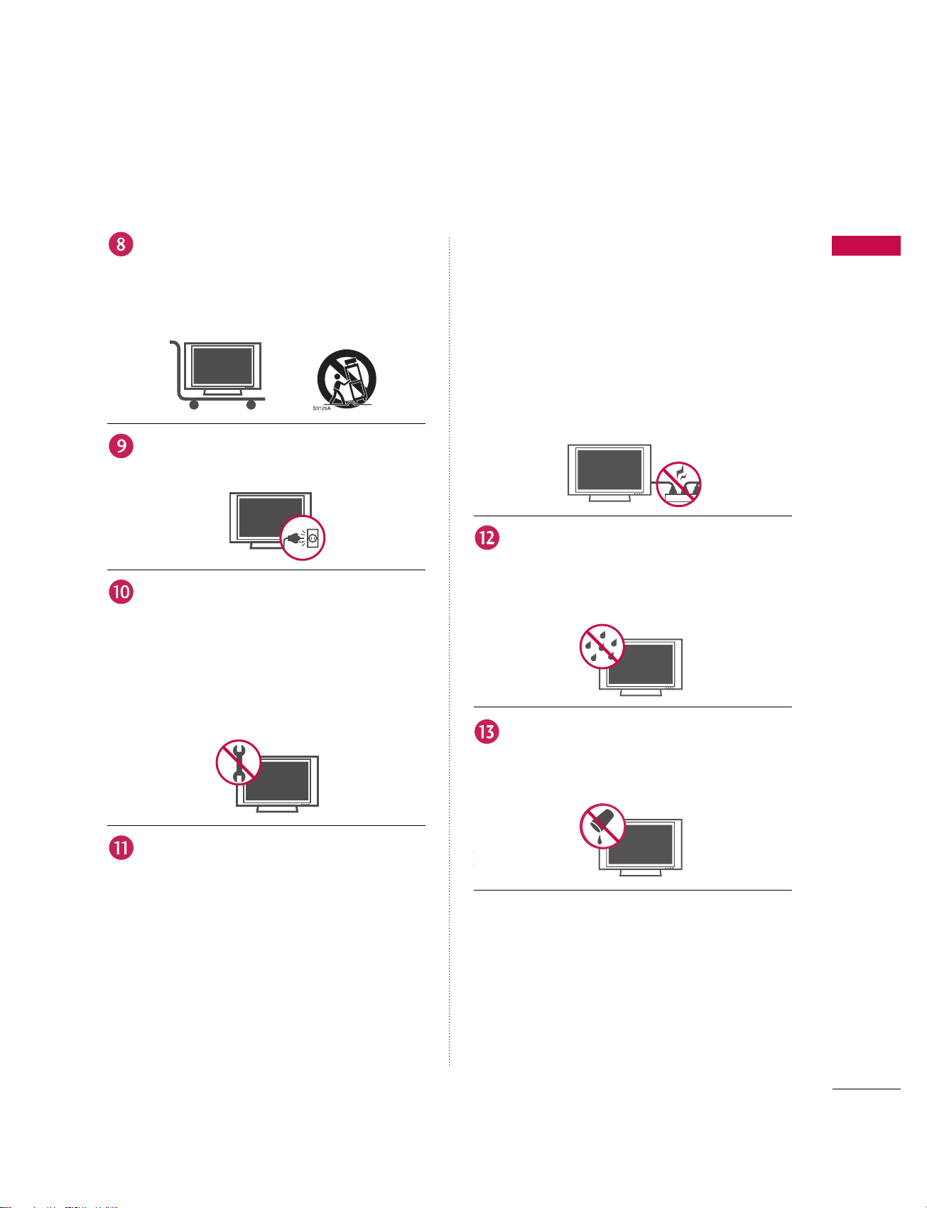
Use only with the cart, stand, tripod, bracket,
or table specified by the manufacturer, or sold
with the apparatus. When a cart is used, use
caution when moving the cart/apparatus
combination to avoid injury from tip-over.
Unplug this apparatus during lightning storms
or when unused for long periods of time.
Refer all servicing to qualified service personnel. Servicing is required when the apparatus
has been damaged in any way, such as powersupply cord or plug is damaged, liquid has
been spilled or objects have fallen into the
apparatus, the apparatus has exposed to rain
or moisture, does not operate normally, or has
been dropped.
CAUTION concerning the Power Cord :
Most appliances recommend they be placed
upon a dedicated circuit; that is, a single outlet circuit which powers only that appliance
and has no additional outlets or branch circuits. Check the specification page of this
owner's manual to be certain.
Do not overload wall outlets. Overloaded wall
outlets, loose or damaged wall outlets, extension cords, frayed power cords, or damaged
or cracked wire insulation are dangerous. Any
of these conditions could result in electric
shock or fire. Periodically examine the cord of
your appliance, and if its appearance indicates
damage or deterioration, unplug it, disconti-
nue use of the appliance, and have the cord
replaced with an exact replacement part by an
authorized servicer. Protect the power cord
from physical or mechanical abuse, such as
being twisted, kinked, pinched, closed in a
door, or walked upon. Pay particular attention
to plugs, wall outlets, and the point where the
cord exits the appliance.
Outdoor Use Marking :
WARNING - To Reduce The Risk Of Fire Or
Electric Shock, Do Not Expose This Appliance
To Rain Or Moisture
Wet Location Marking : Apparatus shall not be
exposed to dripping or splashing and no
objects filled with liquids, such as vases, shall
be placed on or over apparatus.
Owner Manual
Owner Manual
Owner Manual
Owner Manual

CONTENTS
4
CONTENTS
WARNING / CAUTION
. . . . . . . . . . . . . . . . . . . . . . . . . . .
1
SAFETY INSTRUCTIONS
. . . . . . . . . . . . . . . . . . . . . . 2-3
INTRODUCTION
Benefits . . . . . . . . . . . . . . . . . . . . . . . . . . . . . . . . . . . 6
TV Guide On Screen
TT MM
Notices for U.S.A/ Digital
Cable Compatibility . . . . . . . . . . . . . . . . . . . . . . . . . 7
Accessories . . . . . . . . . . . . . . . . . . . . . . . . . . . . . . 8
Controls
(Model Name: 50PC1DR/50PC1DRA) . . . 10
Connection Options
(Model Name: 50PC1DR/50PC1DRA) . . . . . . . . . . . 11
Controls (Model Name: 42LB1DR/42LB1DRA) . . 12
Connection Options
(Model Name: 42LB1DR/42LB1DRA) . . . . . . . . . . . . 13
Remote Control Key Functions . . . . . . . . . . . 14-15
INSTALLATION
Attaching the TV to a Wall
. . . . . . . . . . . . . . . . . . . . . . . . . . . . . . 16
Wire Arrangement
. . . . . . . . . . . . . . . . . . . . . . . . . . . . . . . . . . . . . . 17-18
Desktop Pedestal Installation
. . . . . . . . . . . . . . . . . . . . . . . . . . . 19
CONNECTIONS & SETUP
Antenna or Cable Connection . . . . . . . . . . .20-21
CableCARD
TM
Setup . . . . . . . . . . . . . . . . . . . . . . 21
HDSTB Setup . . . . . . . . . . . . . . . . . . . . . . . 22-24
VCR Setup . . . . . . . . . . . . . . . . . . . . . . . . . . 25-26
External A/V Source Setup . . . . . . . . . . . . . . . . . 27
AV Out Setup . . . . . . . . . . . . . . . . . . . . . . . . . . . 28
Digital Audio Output . . . . . . . . . . . . . . . . . . . . . 29
DVD Setup . . . . . . . . . . . . . . . . . . . . . . . . . . .30-31
PC Setup . . . . . . . . . . . . . . . . . . . . . . . . . . . . 32-35
BASIC OPERATION
Turning the TV on . . . . . . . . . . . . . . . . . . . . . . . . 36
On-screen Menus Language Selection . . . . . . . 37
Initial Channel Search (EZ Scan) . . . . . . . . . . . . 38
Channel Selection . . . . . . . . . . . . . . . . . . . . . . . .39
Volume Adjustment . . . . . . . . . . . . . . . . . . . . . . . 39
TV GUIDE ON SCREENTMSYSTEM
TV Guide On Screen
TM
Setup . . . . . . . . . . . . 40-43
TV Guide On Screen
TM
Feature . . . . . . . . . . 44-64
- Overview
- Screen Components
- Panel Menu
- Main Services
Listings | Search | Recordings
Schedule | Setup
- Record And Remind Features
Record | Remind
SPECIAL FUNCTIONS
DVR (Digital Video Recorder)
Timeshift . . . . . . . . . . . . . . . . . . . . . . . . . . . . 65-67
Recording . . . . . . . . . . . . . . . . . . . . . . . . . . . 68-70
Manual Recording . . . . . . . . . . . . . . . . . . . . . . . . 71
Recorded TV . . . . . . . . . . . . . . . . . . . . . . . . . 72-77
PIP/POP/Twin Picture (Multiple Screen)
Watching PIP/POP/Twin Picture . . . . . . . . . . . . .78
Selecting an Input Signal Source for PIP/Twin Picture 79
TV Program Selection for PIP . . . . . . . . . . . . . . . 79
Moving the PIP sub picture . . . . . . . . . . . . . . . . 79
Swapping PIP/Twin Picture . . . . . . . . . . . . . . . . . 80
Adjusting Main and Sub Picture Sizes for Twin Picture 80
POP(Picture-out-of-Picture: Channel Scan) . . . . . . . 81

CONTENTS
5
TV MENU
On Screen Menus Selection and Adjustment . . 82
Setup(Channel)
Auto Channel Search (EZ Scan) . . . . . . . . . . . . 83
Manual Channel Search (Manual Scan) . . . . . . . 84
Channel Edit . . . . . . . . . . . . . . . . . . . . . . . . . . . . .85
DTV Signal Strength . . . . . . . . . . . . . . . . . . . . . . 86
Main Input Source Selection . . . . . . . . . . . . . . . 87
Auto Link . . . . . . . . . . . . . . . . . . . . . . . . . . . . . . . 88
Input Label . . . . . . . . . . . . . . . . . . . . . . . . . . . . . 89
Video Adjustment
Auto Picture Control (EZ Picture) . . . . . . . . . . . 90
Adaptive Picture Mode (APM). . . . . . . . . . . . . . .91
Manual Picture Control (EZ Picture-User Option) . .92
Color Temperature Control . . . . . . . . . . . . . 93-94
XD . . . . . . . . . . . . . . . . . . . . . . . . . . . . . . . . . . . . 95
Advanced - Cinema 3:2 Mode
. . . . . . . . . . . . . . . . . . . . . . . . . 96
Advanced - Black Level
. . . . . . . . . . . . . . . . . . . . . . . . . . . . . . . . . . . . 97
Video Reset . . . . . . . . . . . . . . . . . . . . . . . . . . . . .98
Audio Adjustment
Audio Language . . . . . . . . . . . . . . . . . . . . . . . . . 99
Auto Volume Leveler (EZ SoundRite) . . . . . . . 100
Auto Sound Control (EZ Sound) . . . . . . . . . . . 101
Manual Sound Control (EZ Sound-user Option) . . 102-103
Balance . . . . . . . . . . . . . . . . . . . . . . . . . . . . . . . .104
TV Speakers On/Off Setup . . . . . . . . . . . . . . . 105
BBE . . . . . . . . . . . . . . . . . . . . . . . . . . . . . . . . . . 106
Stereo/SAP Broadcast Setup . . . . . . . . . . . . . . 107
Time Setting
Auto Clock Setup . . . . . . . . . . . . . . . . . . . . . . . 108
Manual Clock Setup . . . . . . . . . . . . . . . . . . . . . .109
On/Off Timer Setup . . . . . . . . . . . . . . . . . . . . . 110
Sleep Timer . . . . . . . . . . . . . . . . . . . . . . . . . . . . .111
Auto Off . . . . . . . . . . . . . . . . . . . . . . . . . . . . . . . 112
.
Optional Features
Aspect Ratio Control . . . . . . . . . . . . . . . . . . . . .113
Caption / Text . . . . . . . . . . . . . . . . . . . . . . 114-115
Caption Option . . . . . . . . . . . . . . . . . . . . . . . . 116
ISM Method (50PC1DR/50PC1DRA only) . . 117
Low Power (50PC1DR/50PC1DRA only) . . . 118
HDD Format . . . . . . . . . . . . . . . . . . . . . . . . . . . .119
Bried Info. . . . . . . . . . . . . . . . . . . . . . . . . . . . . . .120
Lock Adjustment
Setting up your password . . . . . . . . . . . . . . . . . 121
Lock System . . . . . . . . . . . . . . . . . . . . . . . . . . . . 122
Set Password . . . . . . . . . . . . . . . . . . . . . . . . . . . 122
Block Channel . . . . . . . . . . . . . . . . . . . . . . . . . . 123
Movie Rating (MPAA) (for USA only)
. . . . . . . . . . . . . . 12 4
TV Rating Children (for USA only)
. . . . . . . . . . . . . . . . . . 12 5
TV Rating General (for USA only) . . . . . . . . . . . . . . . . . . . 12 5
TV Rating English (for Canada only)
. . . . . . . . . . . . . . . 12 6
TV Rating French (for Canada only)
. . . . . . . . . . . . . . . 12 6
Input Block . . . . . . . . . . . . . . . . . . . . . . . . . . . . 127
CableCARDTMFunction
Cable menu options . . . . . . . . . . . . . . . . . . . . . .128
Scrambled channel . . . . . . . . . . . . . . . . . . . . . . 129
Cable Channel List . . . . . . . . . . . . . . . . . . . . . . .130
Emergency Message Alert . . . . . . . . . . . . . . . . 130
APPENDIX
External Control Device Setup . . . . . . . . . .131-137
IR Codes . . . . . . . . . . . . . . . . . . . . . . . . . .138-139
Programming the Remote Control . . . . . . . . . 140
Remote Control Codes . . . . . . . . . . . . . . 141-143
Troubleshooting Checklist . . . . . . . . . . . . 144-146
Maintenance . . . . . . . . . . . . . . . . . . . . . . . . . . . 147
Product Specifications . . . . . . . . . . . . . . . . . . . 147

INTRODUCTION
6
BENEFITS
INTRODUCTION
What is a Plasma TV ?
Using plasma is the best way to achieve flat panel
displays with excellent image quality and large screen
sizes that are easily viewable. The Plasma TV can be
thought of as a descendant of the neon lamp and or
a series of fluorescent lamps.
How does it work?
Plasma TV is an array of cells, known as pixels, which
are comprised of three sub-pixels, corresponding to
the colors red, green, and blue. Gas in a plasma state
is used to react with phosphors in each sub-pixel to
produce colored light (red, green, or blue). These
phosphors are the same types used in Cathode Ray
Tube (CRT) devices such as televisions and common
computer monitors.
Plasma TV offers a rich, dynamic display because
each sub-pixel is individually controlled by advanced
electronics to produce over 16 million different colors. This means that you get perfect images that are
easily viewable in a display that is fewer than five
inches thick.
160° - Wide angle range of vision
Your flat panel plasma screen offers an exceptionally
broad viewing angle of over 160 degrees. This means
that the display is clear and visible to viewers anywhere in the room.
Wide Screen
The wide screen offers a theater-like experience in
your own home.
Multimedia
Connect your plasma display to a PC and use it for
conferencing, games, and Internet browsing. The
Picture-in-Picture feature allows you to view your PC
and video images simultaneously.
Versatile
The light weight and thin size makes it easy to install
your plasma display in a variety of locations where
conventional TVs do not fit.
The Plasma TV Manufacturing Process: a few
minute colored dots may be present on the
Plasma TV screen
The Plasma TV is composed of 0.9
to 2.2 million
cells. A few cell defects will normally occur in the
Plasma TV manufacturing process. Several tiny,
minute colored dots visible on the screen should be
acceptable. This also occurs in other Plasma TV
manufacturers' products. The tiny dots appearing
does not mean that this Plasma TV is defective. Thus
a few cell defects are not sufficient cause for the
Plasma TV to be exchanged or returned. Our production technology minimizes these cell defects during the manufacture and operation of this product.
Cooling Fan Noise
In the same way that a fan is used in a PC computer
to keep the CPU (Central Processing Unit) cool, the
Plasma TV is equipped with cooling fans to cool the
Monitor and improve its reliability. Therefore, a certain level of noise could occur while the fans are
operating and cooling the Plasma TV.
The fan noise doesn't have any negative effect on
the Plasma TV's efficiency or reliability. The noise
from these fans is normal during the operation of
this product. We hope you understand that a certain
level of noise from the cooling fans is acceptable and
is not sufficient cause for the Plasma TV to be
exchanged or returned.
FOR LCD TV
If the TV feels cold to the touch, there may be a
small “flicker” when it is turned on. This is normal,
there is nothing wrong with TV.
Some minute dot defects may be visible on the
screen, appearing as tiny red, green, or blue spots.
However, they have no adverse effect on the monitor's performance.
Avoid touching the LCD screen or holding your finger(s) against it for long periods of time. Doing so
may produce some temporary distortion effects on
the screen.
OOnn DDiissppoossaall
a. The fluorescent lamp used in this product con-
tains a small amount of mercury.
b. Do not dispose of this product with general
household waste.
c. Disposal of this product must be carried out in
accordance to the regulations of your local
authority.
INTRODUCTION
7
TM
TV GUIDE ON SCREENTMNOTICES FOR U.S.A.
This digital television is capable of receiving basic analog, digital basic and digital premium cable
television programming by direct connection to a cable system providing such programming. A
security card provided by your cable operator is required to view encrypted digital programming.
Cable operator enhanced program (For example, electronic program guide provided by the cable
operator), and data enhanced television service may require the use of a set top box. For more
information contact your local cable operator.
Trademark Notice
In the United States, TV GUIDE and other related marks are registered marks of Gemstar-TV Guide
International, Inc. and/or one of its affiliates. In Canada, TV GUIDE is a registered mark of
Transcontinental Inc., and is used under license by Gemstar-TV Guide International, Inc.
License Notice
The TV Guide On ScreenTMsystem is manufactured under license from Gemstar-TV Guide
International, Inc. and/or one of its affiliates.
Patent Notice
The TV Guide On ScreenTMsystem is protected by one or more of the following issued United
States patents 6,498,895, 6,418,556, 6,331,877; 6,239,794; 6,154,203; 5,940,073; 4,908,713;
4,751,578; 4,706,121.
Use of the CableCARD
TM
TradeMark.
“CableCARD
TM
is a trademark of Cable Television Laboratories, Inc.”
DIGITAL CABLE COMPATIBILITY
Official term for an HDTV that conforms to the plugand-play digital cable TV standard using POD (Point
of Deployment) access cards, also called
CableCARDs, that allow users to plug the cable
directly into an HDTV set and enjoy HDTV and digital cable without having to use a separate set-top
box.
is a trademark of SRS Labs, Inc.
TruSurround XT technology is incorporated under
license from SRS Labs, Inc.
Manufactured under license from BBE Sound, Inc.
A Digital Video Recorder (DVR) is a device that
empowers you to control what you watch, when you
watch it. It allows you to store and access TV programs - functioning like a VCR, but with no videotape. With a DVR, you can also pause live TV and
choose the shows you want to record through an
electronic program guide.
R
TruSurround XT
Manufactured under license from Dolby Laboratories.
“
Dolby
“and the double-D symbol are trademarks of
Dolby Laboratories.
High-definition television. High-resolution digital
television broadcast and playback system composed
of roughly a million or more pixels, 16:9 aspect-ratio
screens, and AC3 digital audio. A subset of digital
television, HDTV formats include 1080i and 720p
resolutions.
HDMITM, the HDMI logo and High-Definition
Multimedia Interface are trademarks or registered
trademarks of HDMI Licensing."
LG's own special digital image generator, consisting
of a full digital image processor, APM mode & six different main picture quality factors.
R
TruSurround XT
INTRODUCTION
8
ACCESSORIES
INTRODUCTION
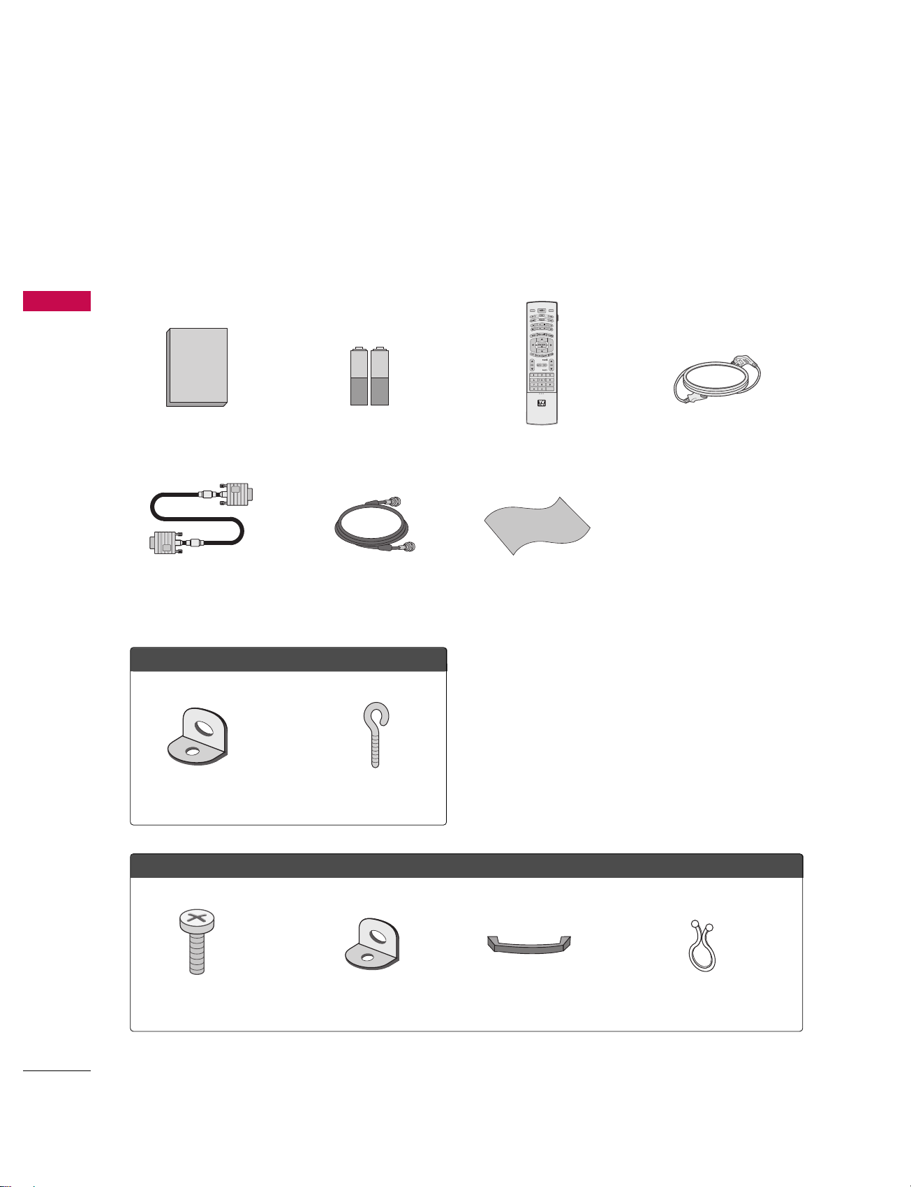
Ensure that the following accessories are included with your plasma display. If an accessory is missing, please
contact the dealer where you purchased the product.
MODE
DAY -
D
A
Y
+
FLASHBK
APM
CC
AUTO DEMO
M/C EJECT
TV INPUT
TV/VIDEO
Owner's Manual
1.5V
1.5V
Owner’s Manual Batteries
D-sub 15 pin Cable
75 Ω Round Cable
Remote Control
Polishing Cloth
Polish the screen with the cloth.
Power Cord
Cable Management
2-TV Bracket Bolts 2-TV Brackets, 2-Wall Brackets
Twister Holder
Arrange the wires with the twister holder.
2-Wall brackets 2-eye-bolts
FFoorr 4422LLBB11DDRR // 4422LLBB11DDRRAA
FFoorr 5500PPCC11DDRR // 5500PPCC11DDRRAA
INTRODUCTION
9
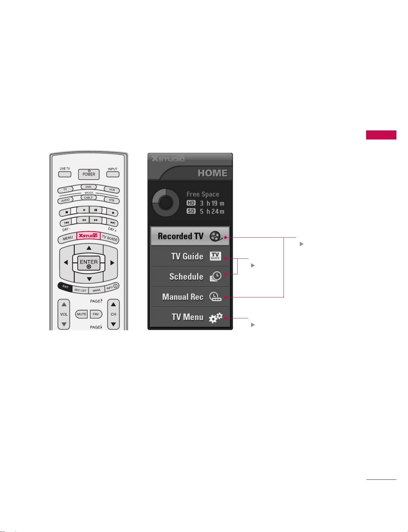
HOME MENU
This menu is a contents guide.
In HOME Menu, you can enter the recorded list of DVR, TV Guide,
Schedule of the TV Guide, Manual Record of DVR or TV Menu.
TV Guide
pp..4400
DVR
pp..6655
TV Menu
pp..8822
INTRODUCTION
10
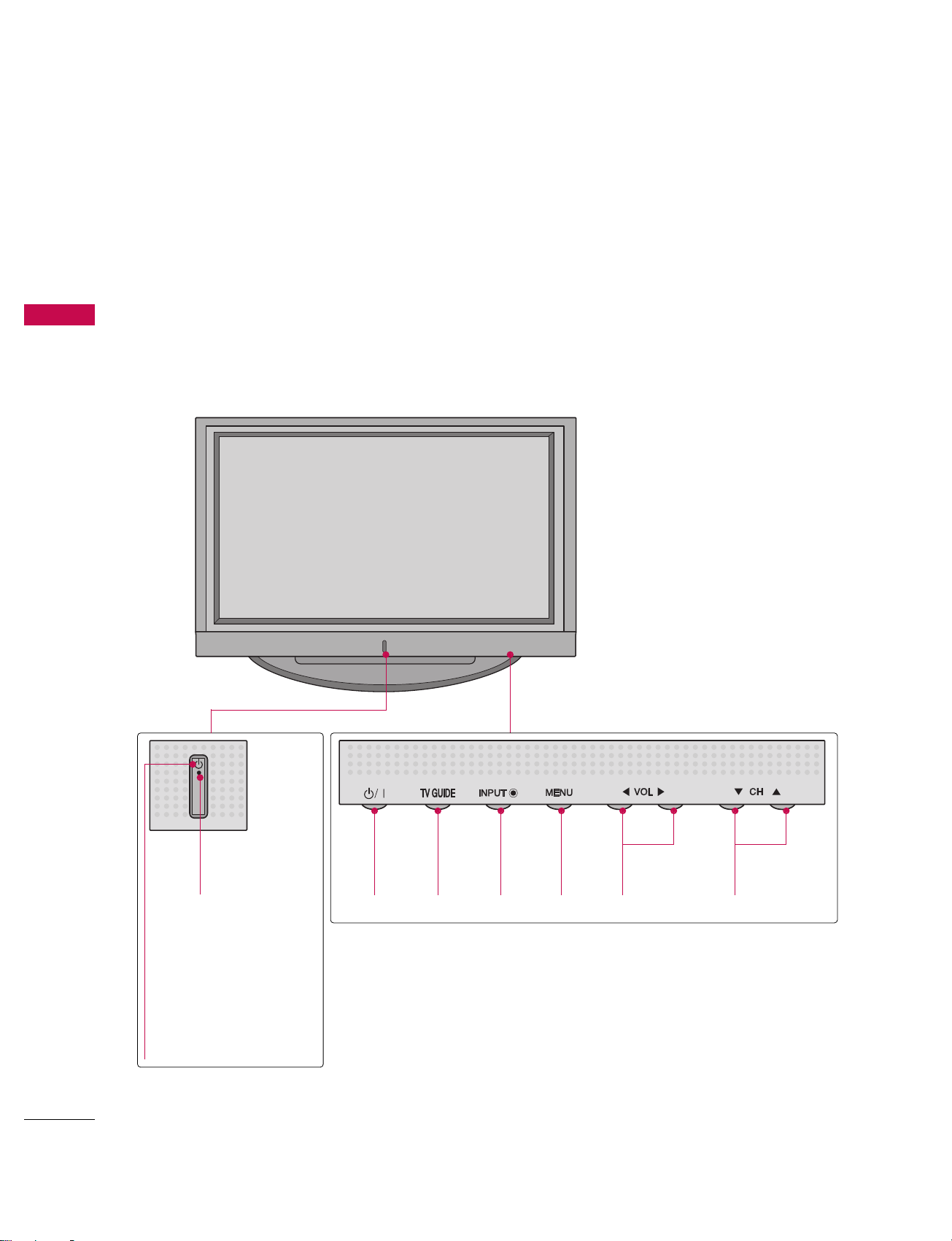
CONTROLS
INTRODUCTION
This is a representation of the front panel of models 50PC1DR, 50PC1DRA series TVs.
■
Here shown may be somewhat different from your TV.
Front Panel Controls
Remote
Control Sensor
POWER
Button
TV
GUIDE
Button
INPUT
Button
MENU
Button
VOLUME
(
FF,GG)Buttons
CHANNEL
(EE,DD)Buttons
Power Standby Indicator
Illuminates red in standby
mode.
When the TV is turned
on, the indicator blinks
white and then illuminates white before the
picture is displayed.
Cable CARD
L/
MONO
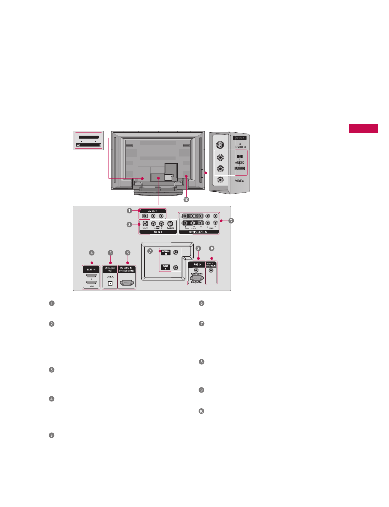
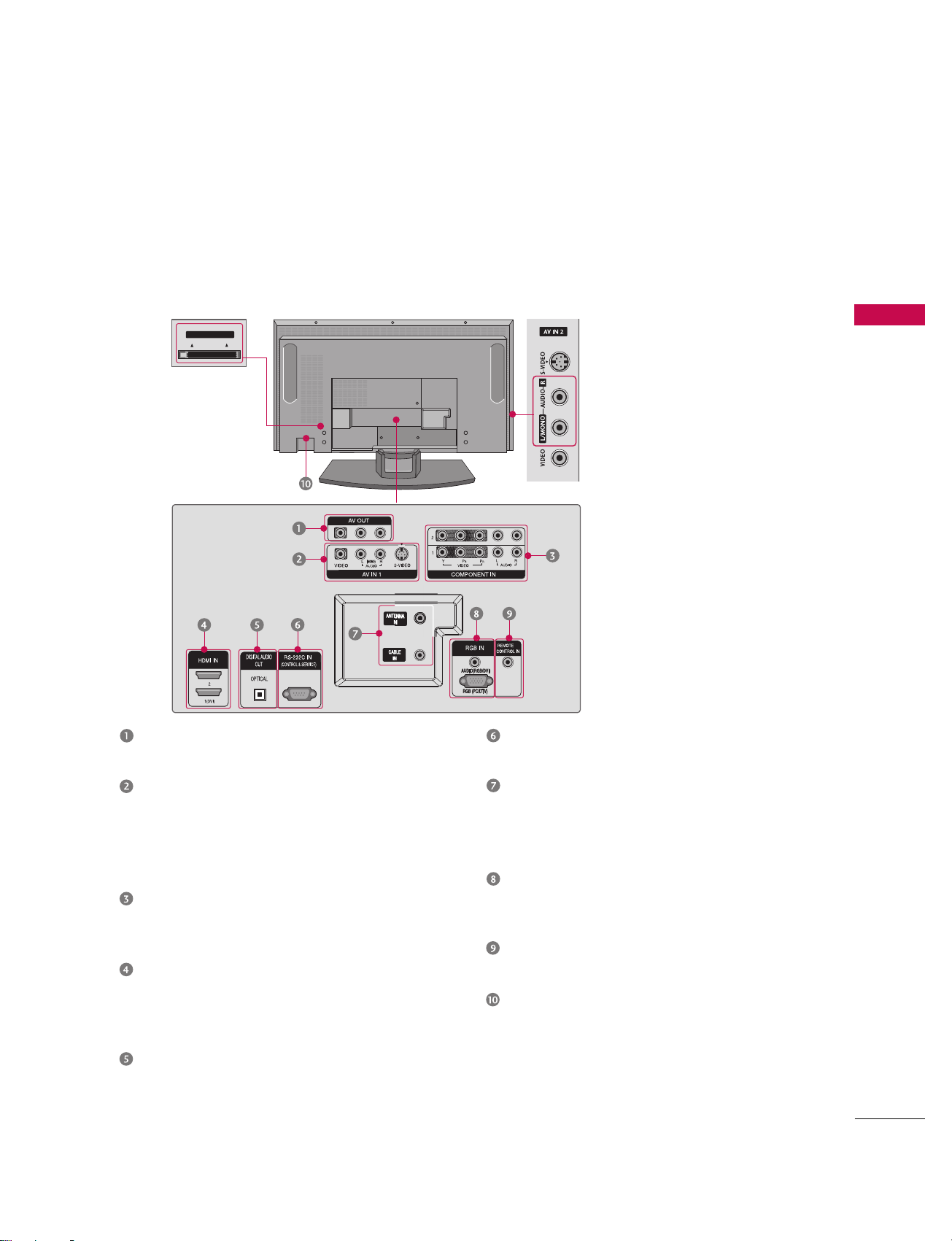
AV OUT
Connect a second TV or monitor.
AV (Audio/Video) IN 1
Connect audio/video output from an external
device to these jacks.
S-VIDEO
Connect S-Video out from an S-VIDEO device.
COMPONENT IN
Connect a component video/audio device to
these jacks.
HDMI IN
Connect a HDMI signal to 1(DVI) or 2.
Or DVI(VIDEO)signal to the 1(DVI) port
with a DVI to HDMI cable.
DIGITAL AUDIO OUT
Connect digital audio from various types of
equipment.
Note: In standby mode, these ports do not work.
RS-232C IN (CONTROL & SERVICE) PORT
Connect to the RS-232C port on a PC.
ANTENNA IN
Connect over-the air signals to this jack.
CABLE IN
Connect cable signals to this jack.
RGB/AUDIO IN
Connect the monitor output from a PC to the
appropriate input port.
Remote Control Port
Connect your wired remote control.
Power Cord Socket
For operation with AC power.
Caution :
Never attempt to operate the TV on DC power.
Back Connection Panel
This is the back panel of models 50PC1DR, 50PC1DRA series TVs.
INTRODUCTION
11
CONNECTION OPTIONS
S-VIDEO Input
Provides better picture quality
than the video input.
AUDIO Input
Connections are available for listening to stereo sound from an
external device.
VIDEO Input
Connects the video signal from a
video device.
CableCARD
™
Used for
CableCARD
™
Cable Service
Provider.
INTRODUCTION
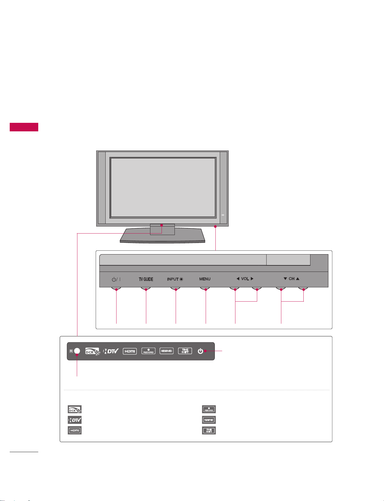
12
CONTROLS
INTRODUCTION
Front Panel Controls
POWER
Button
TV
GUIDE
Button
INPUT
Button
MENU
Button
VOLUME
(
FF,GG
)Buttons
CHANNEL
(
EE,DD
)Buttons
This is a representation of the front panel of models 42LB1DR, 42LB1DRA series TVs.
■
Here shown may be somewhat different from your TV.
INDEX
Digital Cable Ready
HDTV mode
HDMI1/DVI or HDMI2 mode
Recording
Setting the reserve record
Operating the TimeShift
Remote Control Sensor
Power Standby Indicator
Illuminates red in standby mode.
When the TV is turned on, the indicator
blinks white and then illuminates white
before the picture is displayed.
INTRODUCTION
13
CONNECTION OPTIONS
This is the back panel of models 42LB1DR, 42LB1DRA series TVs.
Back Connection Panel
S-VIDEO Input
Provides better picture quality than the
video input.
AUDIO Input
Connections are available for listening to
stereo sound from an external device.
VIDEO Input
Connects the video signal from a video
device.
AV OUT
Connect a second TV or monitor.
AV (Audio/Video) IN 1
Connect audio/video output from an external
device to these jacks.
S-VIDEO
Connect S-Video out from an S-VIDEO device.
COMPONENT IN
Connect a component video/audio device to
these jacks.
HDMI IN
Connect a HDMI signal to 1(DVI) or 2.
Or DVI(VIDEO)signal to the 1(DVI) port
with a DVI to HDMI cable.
DIGITAL AUDIO OUT
Connect digital audio from various types of
equipment.
Note: In standby mode, these ports do not work.
RS-232C IN (CONTROL & SERVICE) PORT
Connect to the RS-232C port on a PC.
ANTENNA IN
Connect over-the air signals to this jack.
CABLE IN
Connect cable signals to this jack.
RGB/AUDIO IN
Connect the monitor output from a PC to the
appropriate input port.
Remote Control Port
Connect your wired remote control.
Power Cord Socket
For operation with AC power.
Caution :
Never attempt to operate the TV on DC power.
CableCARD
™
Used for
CableCARD
™
Cable Service
Provider
Cable CARD
Cable CARD
INTRODUCTION
14
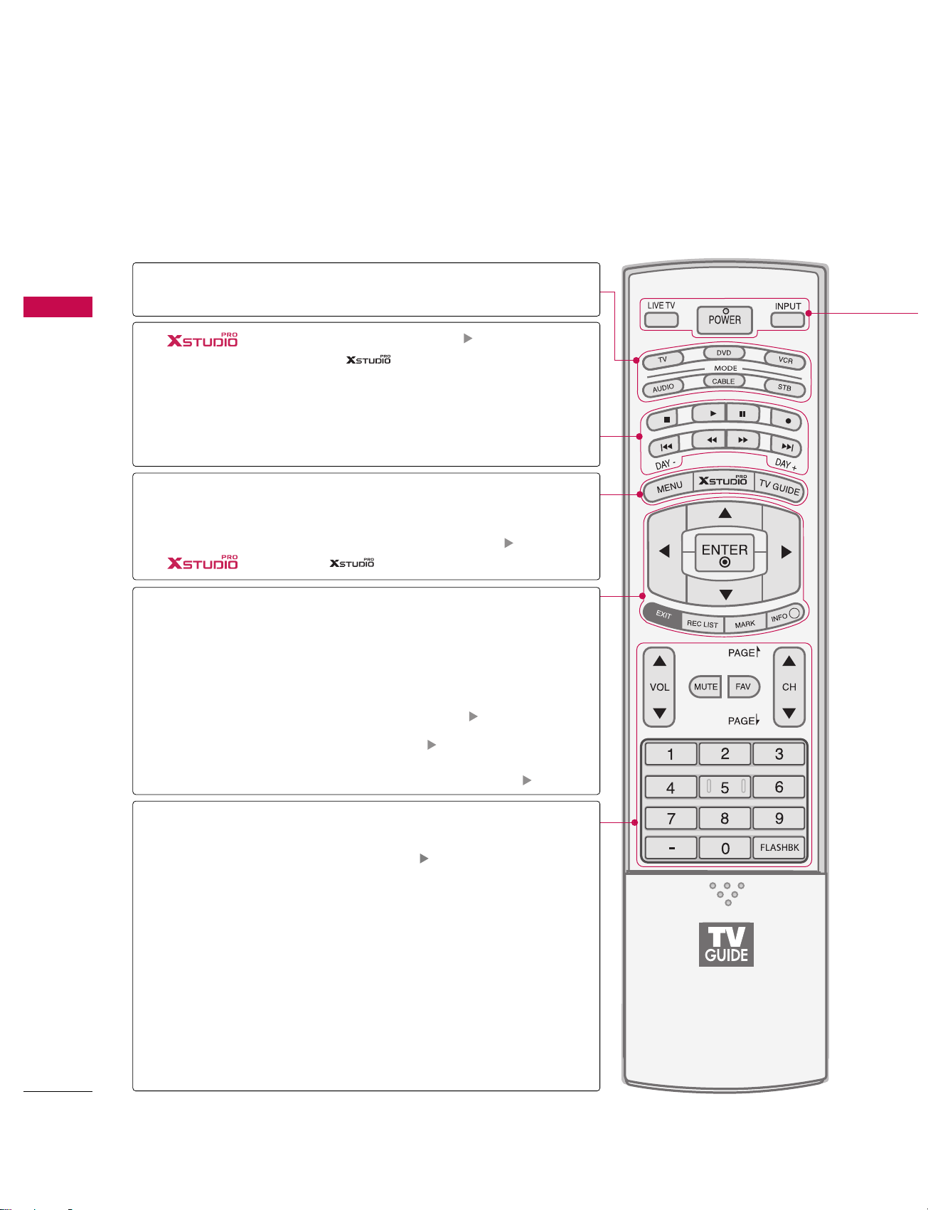
REMOTE CONTROL KEY FUNCTIONS
When using the remote control, aim it at the remote control sensor on the TV.
INTRODUCTION
APM
CC
AUTO DEMO
M/C EJECT
i
MODE
DAY+/DAY-
THUMBSTICK
(Up/Down/Left
Right/ENTER)
EXIT
REC LIST
MARK
INFO
VOLUME UP
/DOWN
MUTE
FAV
CHANNEL
UP/DOWN
PAGE UP/
PAGE DOWN
FLASHBK
— (DASH)
Select the remote operating mode: TV, DVD, VCR,
AUDIO, CABLE or STB.
■
Use for DVR record or trick play. pp..6677,, 7755
■
Controls the mode.
■
For further details, see the DDVV RR section.
Control video cassette recorders or DVD players.
Move the Listings Grid forward or backward in 24 hour
increments.
Displays the main menu. Enters or exits a Panel Menu
in the TV Guide On Screen system.
Displays the TV Guide On Screen system.
pp ..4400
Enter to the mode.
Navigate the on-screen menus and adjust the system
settings to your preference.
Clear all on-screen displays and return to TV viewing from
any menu.
Display the thumbnail recorded list.
pp ..7722
Enter the selected functions. pp..7733
Display information at the top of the screen. pp..112200
Increase/decrease the sound level.
Switch the sound on or off.
pp..3399
Scroll through the programmed Favorite channels.
Select available channels.
Move from one full set of screen information
to the next one.
Tune to the last channel viewed.
Used to enter a program number for multiple
program channels such as 2-1, 2-2, etc.
mode control
buttons
NUMBER button
VCR/DVD
buttons
MENU
TV GUIDE
TIMER
RATIO
ADJUST
INTRODUCTION
15
POWER
LIVE TV
INPUT
Turns your TV or any other programmed equipment on or off, depending on the mode.
In AV 1-2, Component 1-2, RGB-DTV (or RGB-PC), HDMI1/DVI, and HDMI2 input sources,
screen returns to the last TV channel.
External input modes rotate in regular sequence: Antenna, Cable, AV1-2, Component 1-2, RGBDTV (or RGB-PC), HDMI1/DVI and HDMI2 (AV 1-2, Component 1-2, RGB-DTV (or RGB-PC),
HDMI1/DVI, and HDMI2 input sources are linked automatically, only if these are connected ).
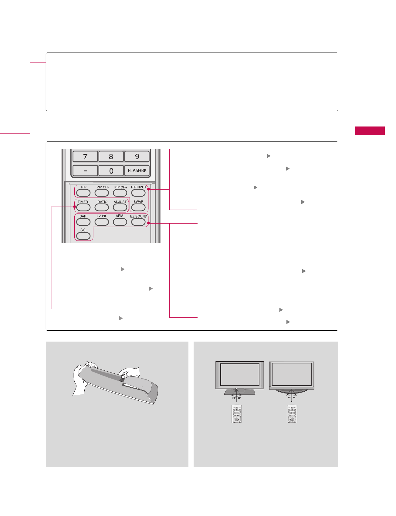
Inside the Sliding Cover
PIP
PIPCH-/PIPCH+
PIP INPUT
SWAP
SAP
EZ PIC
APM
EZ SOUND
CC
Switches the sub picture PIP, POP, Twin picture or off mode.
pp.. 7788
Changes the PIP channel. pp.. 7799
Select the connected input source for the
sub-picture.
pp.. 7799
Exchange the main/sub images. pp.. 8800
Select MTS sound: Mono, Stereo, and SAP
analog mode. Change the audio language
DTV mode.
Adjust the factory preset picture depend
on the viewing environment.
Compare the Daylight, Normal, Night Time
and User1(or2) on the screen.
pp.. 9911
Select the appropriate type of sound for
type of program.
Select closed caption. pp.. 111144
(*In DTV/CADTV modes pp.. 111155)
Installing Batteries
■
Open the battery compartment cover on the
back side and install the batteries matching correct polarity (+with +,-with -).
■
Install two 1.5V AA batteries. Don’t mix old or
used batteries with new ones.
■
Close cover.
■
Use a remote control up to 7 meters distance and 30
degree (left/right) within the receiving unit scope.
■
Dispose of used batteries in a recycle bin to preserve environment.
Remote control effective range
Select the amount of time
before your TV turns off
automatically.
pp..111111
Change the aspect ratio. pp..111133
Adjust the screen
position,size,and phase
in PC mode.
pp..3355
LIVE TV
INPUT
MODE
D
-
A
Y
Y
A
+
D
LIVE TV
INPUT
MODE
D
-
A
Y
Y
A
+
D
INSTALLATION
16
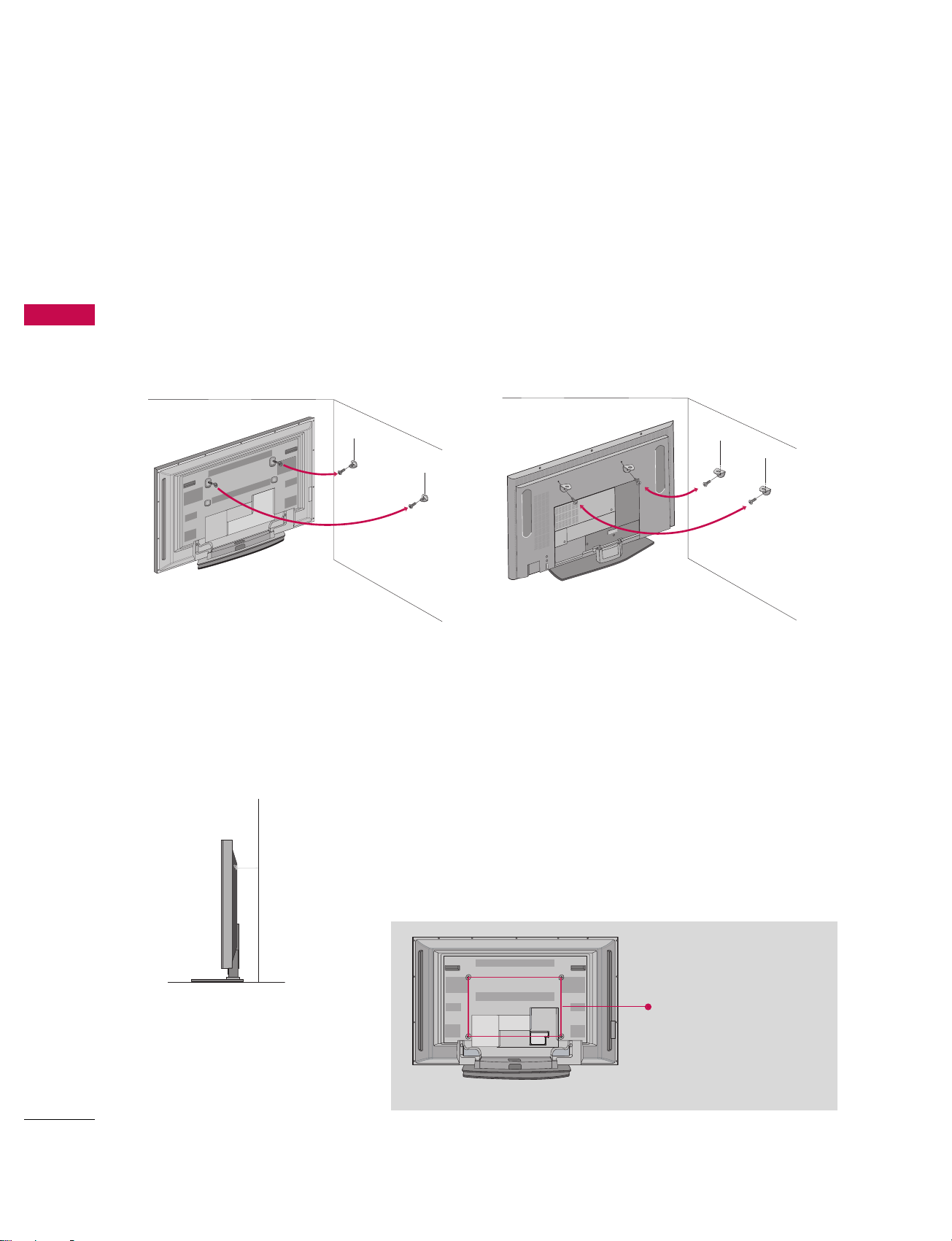
ATTACHING THE TV TO A WALL
We recommend that you set up the TV close to a wall so it cannot fall over if pushed backwards.
Additionally, we recommend that the TV be attached to a wall so it cannot be pulled in a forward direction, potentially causing injury or damaging the product.
Caution: Please make sure that children don’t climb on or hang from the TV.
■
Insert the eye-bolts (or TV brackets and bolts) to tighten the product to the wall as shown in the picture.
*Insert the eye-bolts and tighten them securely in the upper holes.
Secure the wall brackets with the bolts (not provided as parts of the product, must purchase separately ) on
the wall. Match the height of the bracket that is mounted on the wall to the holes in the product.
Ensure the eye-bolts or brackets are tightened securely.
■
Use a sturdy rope (not provided as parts of the product, must purchase separately) to tie the product. It is safer to tie the rope so it becomes horizontal
between the wall and the product.
50PC1DR/50PC1DRA 42LB1DR/42LB1DRA
INSTALLATION
VESA Mounting
These 4 threaded holes are
available for attaching the
bracket provided with the
accessory wall-mount
installation kit.
600mm
400
mm
INSTALLATION
17
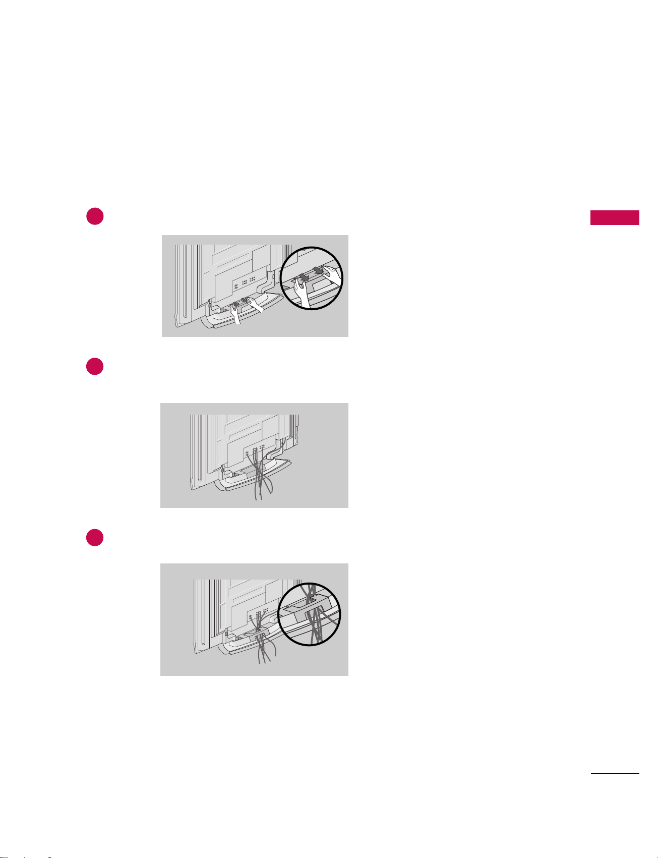
50PC1DR/50PC1DRA
WIRE ARRANGEMENT
Hold the CABLE MANAGEMENT with both hands and pull it backward as shown.
Connect the cables as necessary.
To connect an additional equipment, see the External equipment Connections section.
1
2
Install the CABLE MANAGEMENT as shown.
3
INSTALLATION
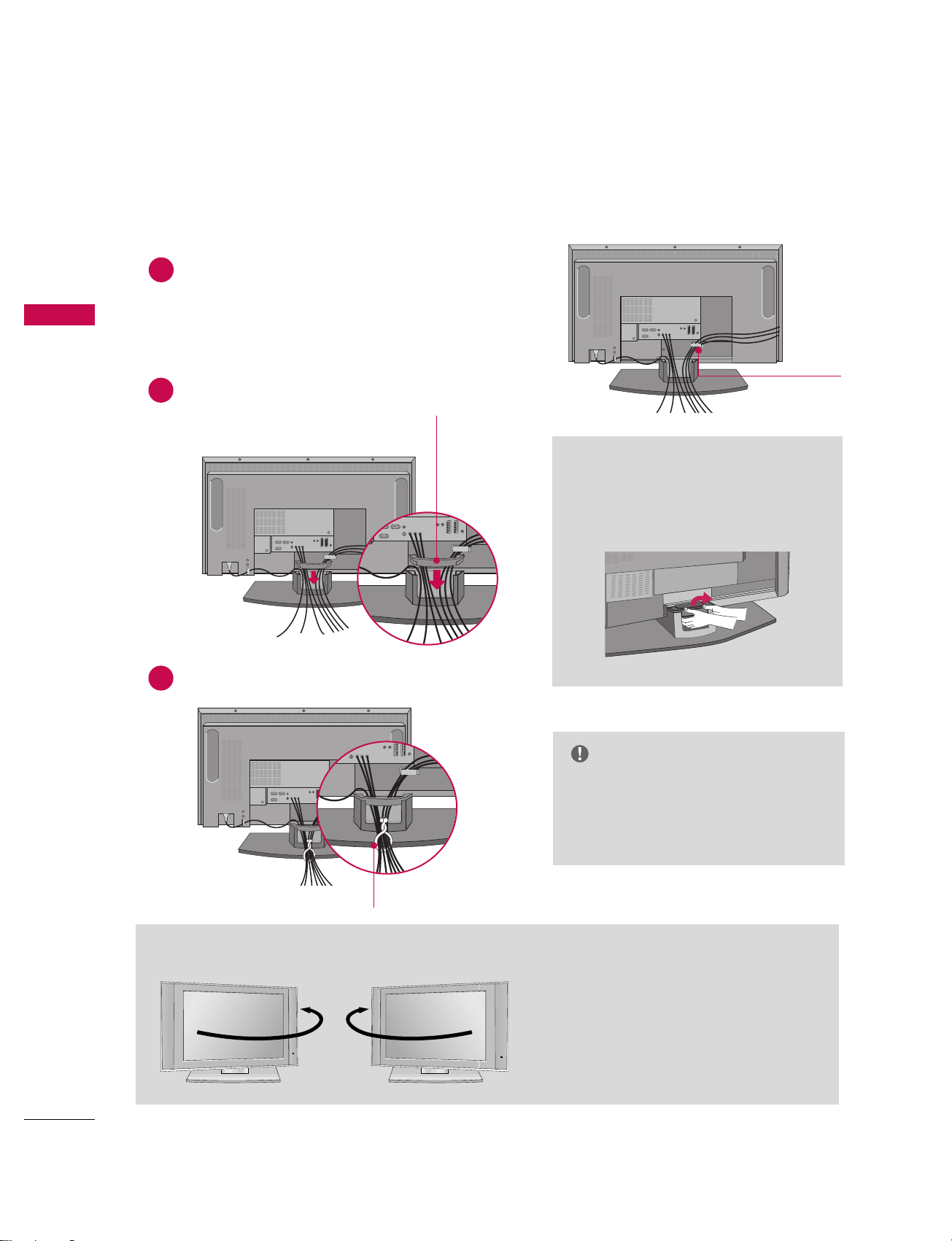
18
INSTALLATION
WIRE ARRANGEMENT
42LB1DR/42LB1DRA
Connect the cables as necessary.
After connecting the cables neatly, arrange the cables to the
Cable Holder.
To connect an additional equipment, see the External
equipment Connections section.
Install the CABLE MANAGEMENT as shown.
How to remove the CABLE
MANAGEMENT
GG
Hold the CABLE MANAGEMENT
with both hands and pull it backward.
CABLE MANAGEMENT
GG
Do not hold the CABLE MANAGEMENT
when moving the product.
- If the product is dropped, you may be
injured or the product may be broken.
NOTE
CABLE HOLDER
1
2
Bundle the cables using the supplied twister holder.
3
TWISTER HOLDER
The TV can be conveniently swiveled on its stand
30
°
to the left or right to provide the optimum
viewing angle.
Swivel Stand (
Only 42LB1DR/42LB1DRA)
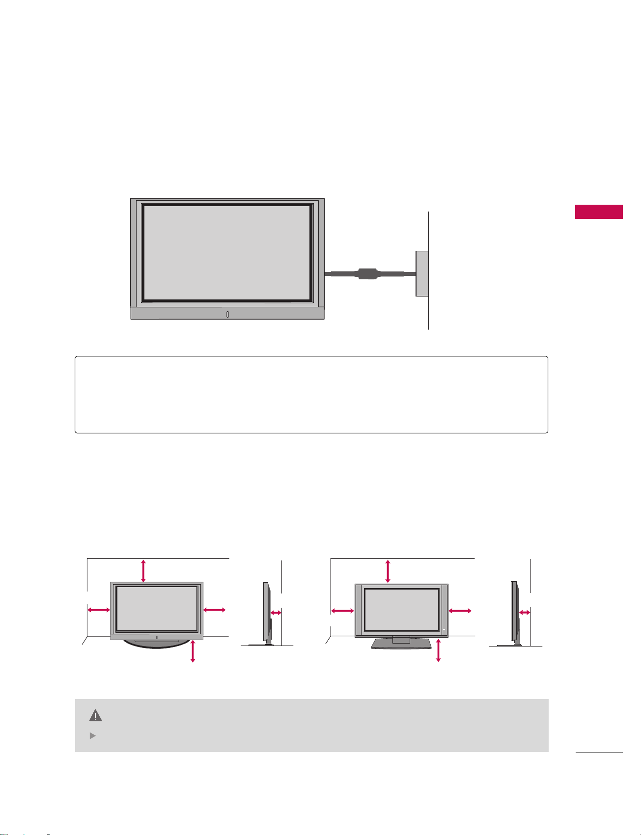
INSTALLATION
19
DESKTOP PEDESTAL INSTALLATION
Power Supply
Short-circuit Breaker
GROUNDING
Ensure that you connect the earth ground wire to prevent possible electric shock. If grounding methods
are not possible, have a qualified electrician install a separate circuit breaker.
Do not try to ground the unit by connecting it to telephone wires, lightening rods, or gas pipes.
■
This manual explains the features available on the 50PC1DR, 50PC1DRA seriesTVs.
■
Here shown may be somewhat different from your TV.
For proper ventilation, allow a clearance of 4 in. on each side and the top, 2.36 in. on the bottom, and 4 in.
from the wall.
CAUTION
Ensure adequate ventilation by following the clearance recommendations.
4 inches
4 inches
4 inches
4 inches
50PC1DR/50PC1DRA 42LB1DR/42LB1DRA
4 inches
4 inches
4 inches
4 inches
CONNECTIONS & SETUP
20
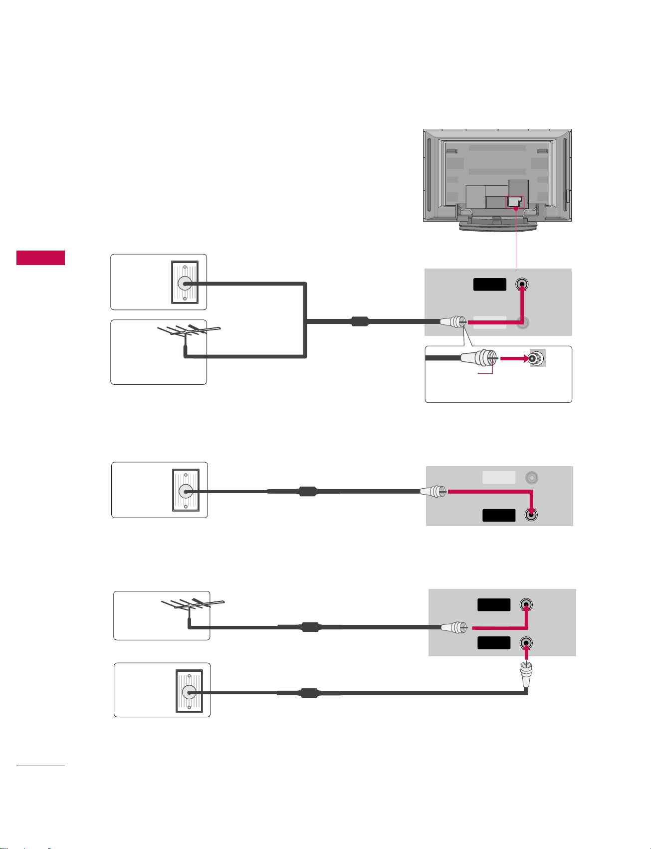
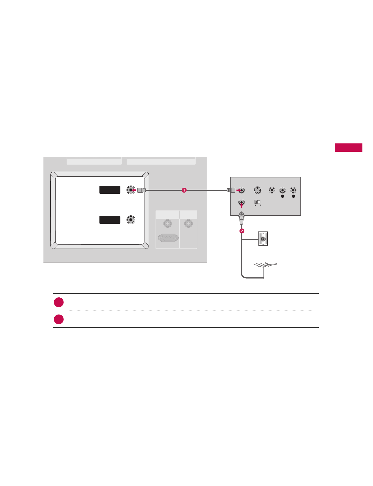
ANTENNA OR CABLE CONNECTION
CONNECTIONS & SETUP
1. Antenna (analog or digital)
Wall Antenna Socket or Outdoor Antenna without a Cable Box
Connections. For optimum picture quality, adjust antenna direction
if needed.
ANTENNA
IN
CABLECABLE
IN
CABLE
IN
ANTENNA
IN
CABLE
IN
CABLE
IN
ANTENNA
IN
CABLE
IN
2. Cable
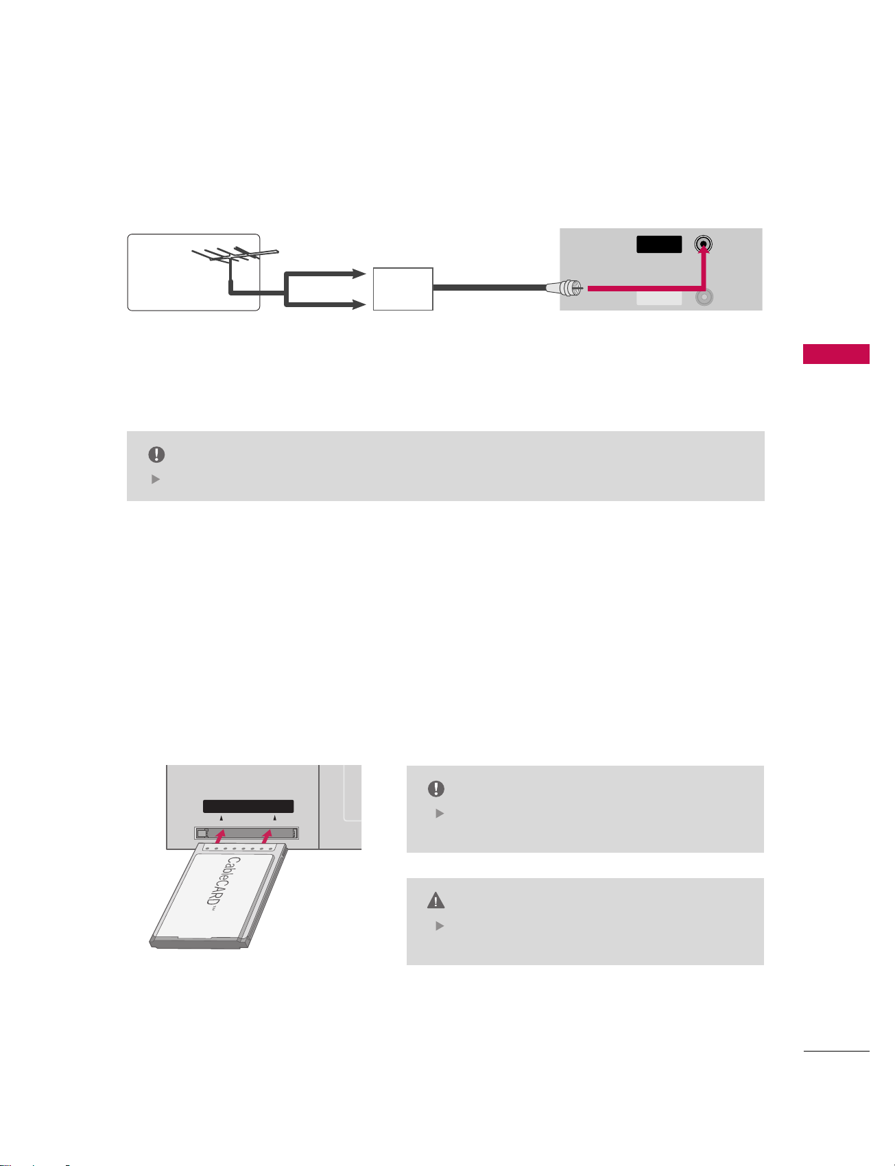
3. Using both cable and antenna
Multi-family Dwellings/Apartments
(Connect to wall antenna socket)
Single-family Dwellings /Houses
(Connect to wall jack for outdoor antenna)
Outdoor
Antenna
(VHF, UHF)
Wall
Antenna
Socket
RF Coaxial Wire (75 ohm)
Bronze Wire
Be careful not to bend the bronze
wire when connecting the antenna.
Cable TV
Wall Jack
Antenna
Cable TV
Wall Jack
RF Coaxial Wire (75 ohm)
RF Coaxial Wire (75 ohm)
RF Coaxial Wire (75 ohm)
CONNECTIONS & SETUP
21
The TV will let you know when the analog, cable, and digital channel scans are complete.
NOTE
CABLE
IN
ANTENNA
IN
CABLECABLE
IN
CABLECARDTMSETUP
1. How to use
Insert the CableCARDTMfrom your cable service provider into the CableCARDTMslot on the back of your TV.
If pairing information about this TV and the CableCARD is displayed on the screen, contact your cable ser-
vice provider.
Cable CARD
■
To improve the picture quality in a poor signal area, please purchase a signal amplifier and install properly.
■
If the antenna needs to be split for two TV’s, install a 2-Way Signal Splitter.
■
If the antenna is not installed properly, contact your dealer for assistance.
Antenna
UHF
Signal
Amplifier
VHF
This TV supports CableCARDTMtechnology from
Motorola, Scientific Atlanta, and SCM.
NOTE
When removing, do not drop it as this may cause
damage to the CableCARD
TM
.
CAUTION
CONNECTIONS & SETUP
22
HDSTB SETUP
CONNECTIONS & SETUP
This TV can receive Digital Over-the-air/Cable signals without an external digital set-top box. However, if you
do receive digital signals from a digital set-top box or other digital external device, refer to the figure as
shown below.
This TV supports HDCP (High-bandwidth Digital Contents Protection)protocol for Digital Contents
(
480p,720p,1080i).
Y L RPB PR
S-VIDEO
VIDEOVIDEO
AUDIO
COMPONENTCOMPONENT IN
HDMI IN
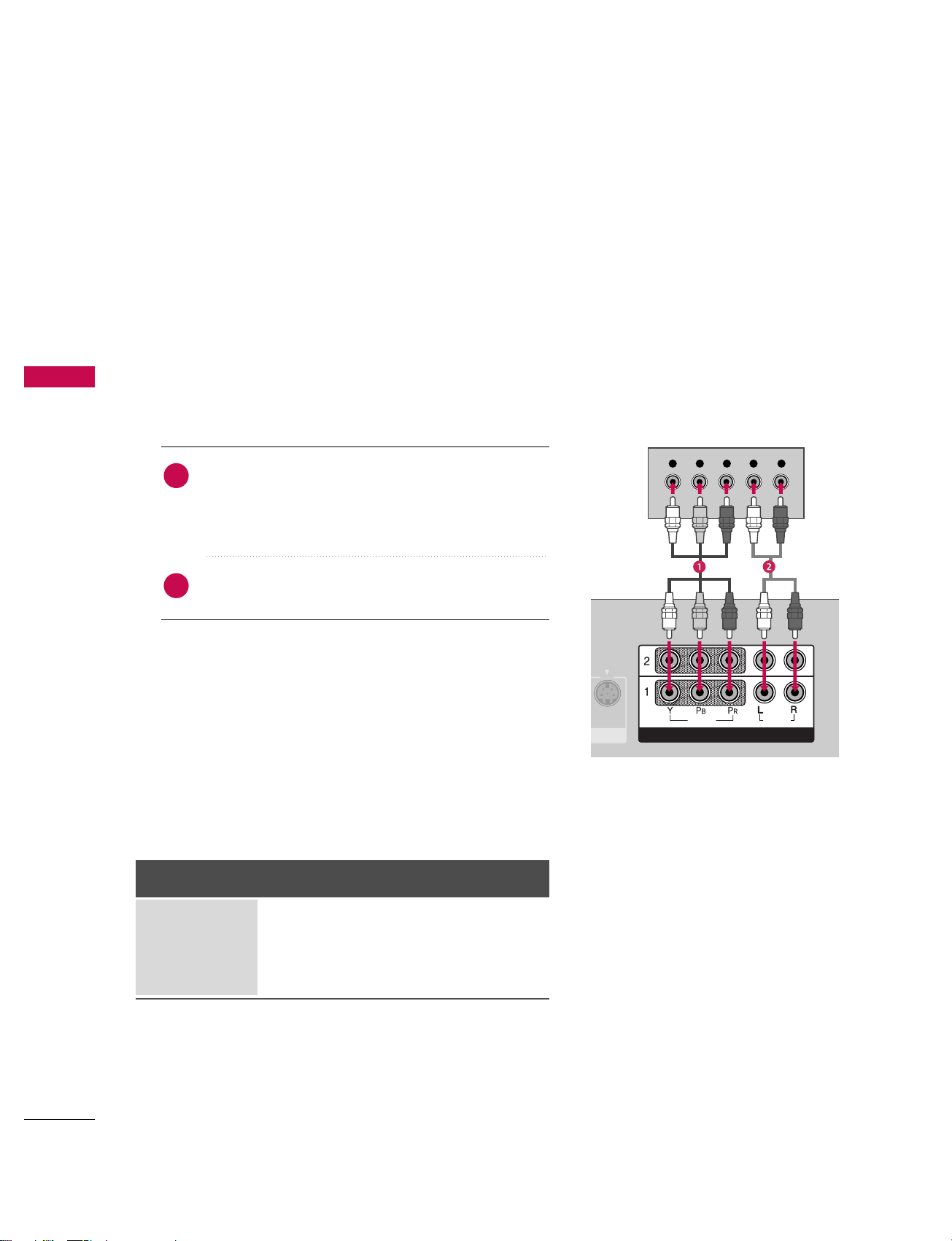
When connecting Component cable
1. How to connect
Connect the video outputs (Y, PB, PR
)
of the digital set
top box to the CCOOMMPPOONNEENNTT IINN VVIIDDEEOO 11 jacks on
the set. Match the jack colors
(Y = green, P
B = blue, and PR
= red).
Connect the audio output of the digital set-top box to
the CCOOMMPPOONNEENNTT IINN AAUUDDIIOO 11 jacks on the set.
2. How to use
■
Turn on the digital set-top box.
(
Refer to the owner’s manual for the digital set-top box.
)
■
Select CCOOMMPPOONNEENNTT 11 input source with using the IINNPPUUTT
button on the remote control.
■
If connected to CCOOMMPPOONNEENNTT IINN 22 input, select CCOOMMPPOO--
NNEENNTT 22 input source.
Signal
480i
480p
720p
10 8 0 i
Component 1/2
Yes
Yes
Yes
Yes
RGB-DTV,
HDMI1/DVI, HDMI2
No
Yes
Yes
Yes
2
1
CONNECTIONS & SETUP
23
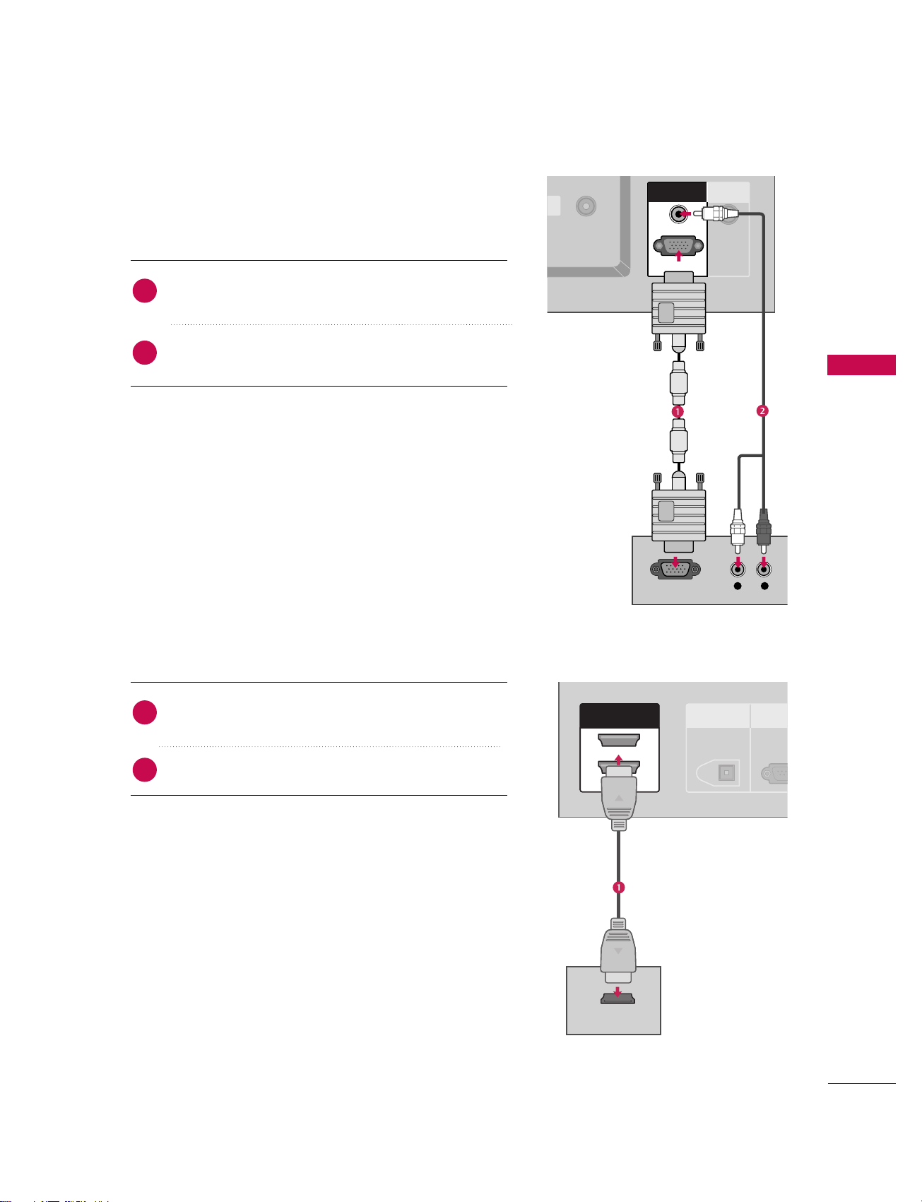
When connecting D-sub 15pin cable
IN
L R
RGB OUTPUT
REMOTE
CONTROL IN
RGB INRGB IN
AUDIO (RGB/DVI)AUDIO (RGB/DVI)
RGB (PCRGB (PC/DTV)DTV)
DIGITAL AUDIO
OUT
OPTICAL
RS-23
(CONTROL &
HDMI INHDMI IN
2
1(DVI)
1(DVI)
HDMI-DTV OUTPUT
Connect the RGB output of the digital set-top box to
the RRGGBB ((PPCC//DDTTVV))jack on the set.
Connect the audio outputs of the set-top box to the
AAUUDDIIOO ((RRGGBB//DDVVII))jack on the set.
1. How to connect
2. How to use
■
Turn on the digital set-top box.
(
Refer to the owner’s manual for the digital set-top box.
)
■
Select RRGGBB--DDTTVV input source with using the IINNPPUUTT button
on the remote control.
When connecting HDMI cable
Connect the digital set-top box to HHDD MMII IINN 11((DDVV II))
or 22 jack on the set.
No separated audio connection is necessary.
1. How to connect
2. How to use
■
Turn on the digital set-top box.
(
Refer to the owner’s manual for the digital set-top box.
)
■
Select HHDDMMII11//DDVVII or HHDDMMII22 input source with using the
IINNPPUUTT button on the remote control.
■
If the digital set-top box supports Auto HDMI function, the
output resolution of the source device will be automatically
set to 1280x720p.
■
If the digital set-top box player does not support Auto HDMI,
you need to set the output resolution appropriately.
To get the best picture quality, adjust the output resolution
of the source device to 1280x720p.
2
1
2
1
CONNECTIONS & SETUP
24
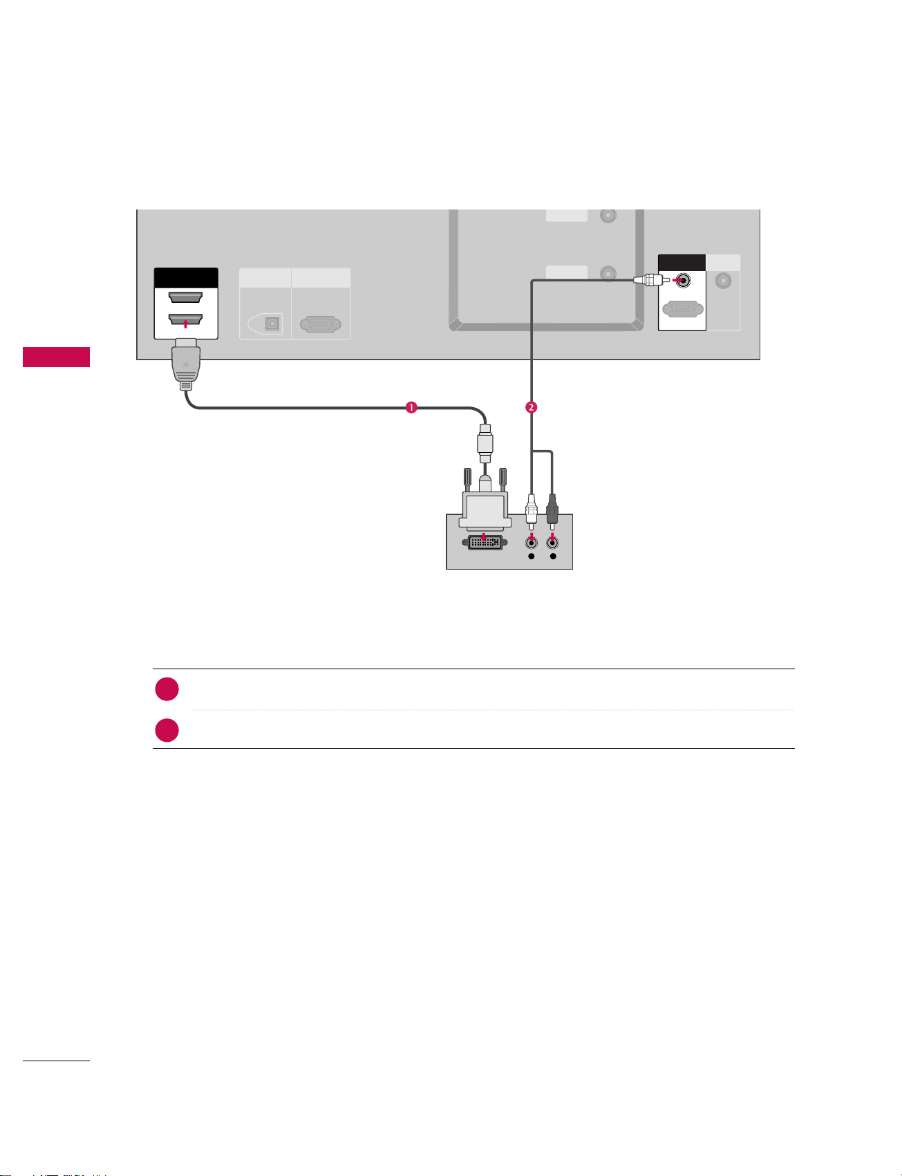
When connecting HDMI to DVI cable
CONNECTIONS & SETUP
ANTENNA
IN
CABLE
IN
VIDEO
AUDIO
COMPONENT IN
HDMI IN
L R
DIGITAL AUDIO
OUT
OPTICAL
RS-232C IN
(CONTROL & SERVICE)
ANTENNAANTENNA
IN
CABLECABLE
IN
HDMI INHDMI IN
2
1(DVI)1(DVI)
DVI-DTV OUTPUT
REMOTE
CONTROL IN
RGB INRGB IN
AUDIO (RGB/DVI)
RGB (PC/DTV)
Connect the DVI output of the digital set-top box to the HHDDMMII IINN 11((DD VVII)) jack on the set.
Connect the audio output of the digital set-top box to the AAUUDDIIOO((RRGGBB//DDVVII))jack on the set.
1. How to connect
■
Turn on the digital set-top box. (Refer to the owner’s manual for the digital set-top box.
)
■
Select HHDDMMII11//DDVVII input source with using the IINNPPUUTT button on the remote control.
2. How to use
2
1
CONNECTIONS & SETUP
25
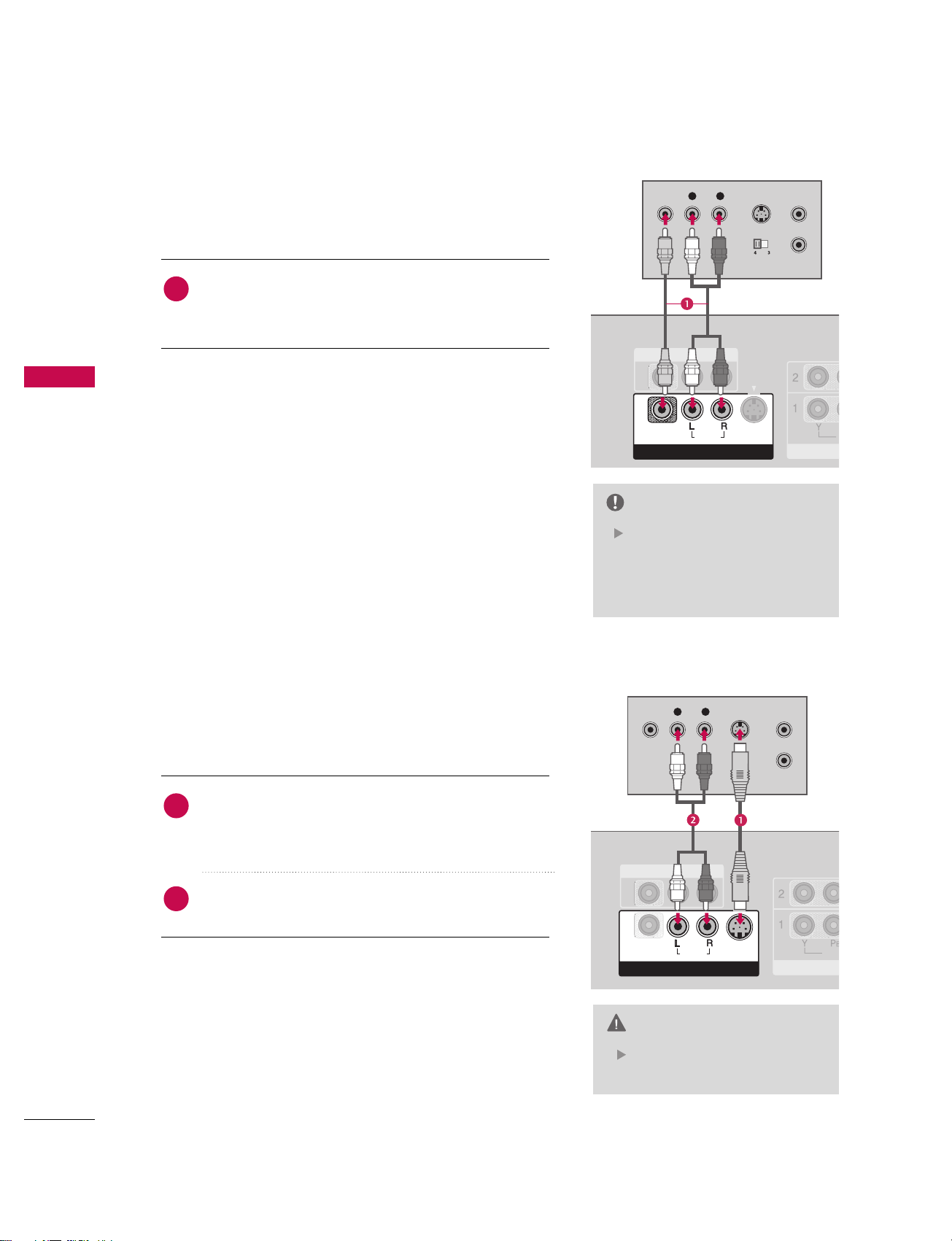
VCR SETUP
When connecting with an antenna
■
To avoid picture noise (interference), leave an adequate distance between the VCR and TV
■
Use the ISM feature in the Option menu to avoid having a fixed image remain on the screen for a long period of time. If the 4:3 picture format is used; the fixed images on the sides of the screen may remain visible
on the screen.
L R
S-VIDEO VIDEO
OUTPUT
SWITCH
ANT IN
ANT OUT
VIDEO
AUDIO
VIDEO
AUDIO
COMPONENT IN
S VIDEO
AV I N 1
RGB (PC/DTV)
RGB IN
AUDIO (RGB/DVI)
REMOTE
CONTROL IN
ANTENNAANTENNA
ININ
CABLECABLE
ININ
Wall Jack
Antenna
Connect the RF antenna out socket of the VCR to the AAnntteennnnaa socket on the set.
Connect the antenna cable to the RF antenna in socket of the VCR.
1. How to connect
■
Set VCR output switch to 3 or 4 and then tune TV to the same channel number.
■
Insert a video tape into the VCR and press PLAY on the VCR. (Refer to the VCR owner’s manual.
)
2. How to use
2
1
CONNECTIONS & SETUP
26
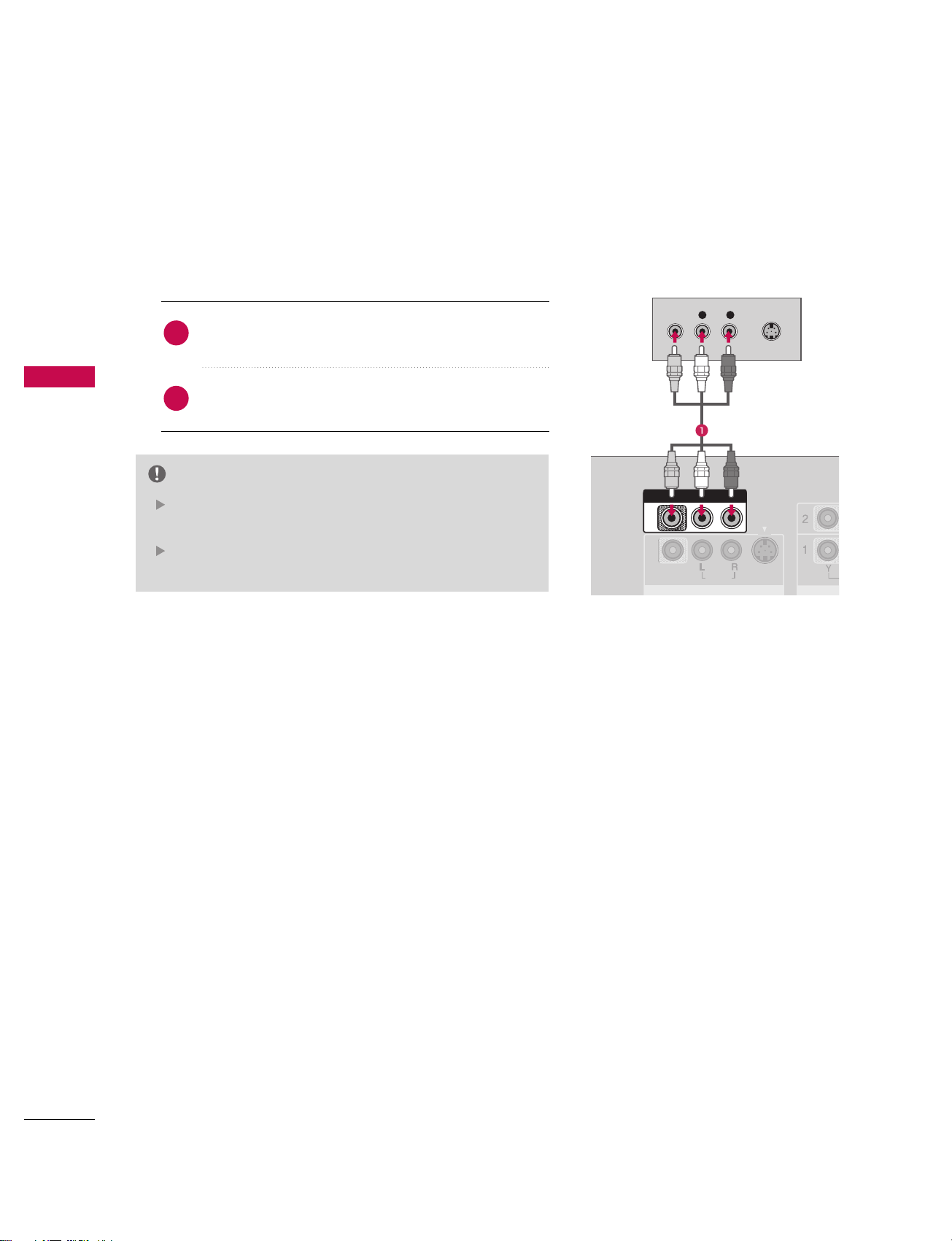
When connecting with a RCA cable
CONNECTIONS & SETUP
Do not connect to both Video
and S-Video at the same time.
CAUTION
L R
S-VIDEOVIDEO
OUTPUT
SWITCH
ANT IN
ANT OUT
V
C
AV OUT
AV IN 1AV IN 1
VIDEOVIDEO
AUDIOAUDIO
(
MONO
)
S-VIDEO
ANTENNA
IN
CABLE
IN
AV IN 1
VIDE
COM
AV O UT
AV IN 1AV IN 1
L R
S-VIDEOVIDEO
OUTPUT
SWITCH
ANT IN
ANT OUT
VIDEO
AUDIO
VIDEO
AUDIOAUDIO
(
MONO
)
S-VIDEOS-VIDEO
Connect the AAUUDDIIOO/VVIIDDEEOO jacks between TV and
VCR. Match the jack colors(Video = yellow, Audio Left =
white,and Audio Right = red)
1. How to connect
2. How to use
■
Insert a video tape into the VCR and press PLAY on the
VCR. (Refer to the VCR owner’s manual.
)
■
Select AA VV 11 input source with using the IINNPP UUTT button on
the remote control.
■
If connected to AAVV IINN 22, select AA VV22 input source.
If you have a mono VCR, connect the audio cable from the
VCR to the AA UUDDIIOO
LL// MMOONNOO jack of the set.
NOTE
When connecting with an S-Video
Connect the S-VIDEO output of the VCR to the SS --
VV II DD EE OO input on the set. The picture quality is
improved; compared to normal composite (RCA cable
)
input.
Connect the audio outputs of the VCR to the AAUUDDIIOO
input jacks on the set.
1. How to connect
2. How to use
■
Insert a video tape into the VCR and press PLAY on the VCR.
(
Refer to the VCR owner’s manual.
)
■
Select AAVV11 input source with using the IINNPPUUTT button on the
remote control.
■
If connected to AAVV IINN 22, select AAVV22 input source.
1
2
1
CONNECTIONS & SETUP
27
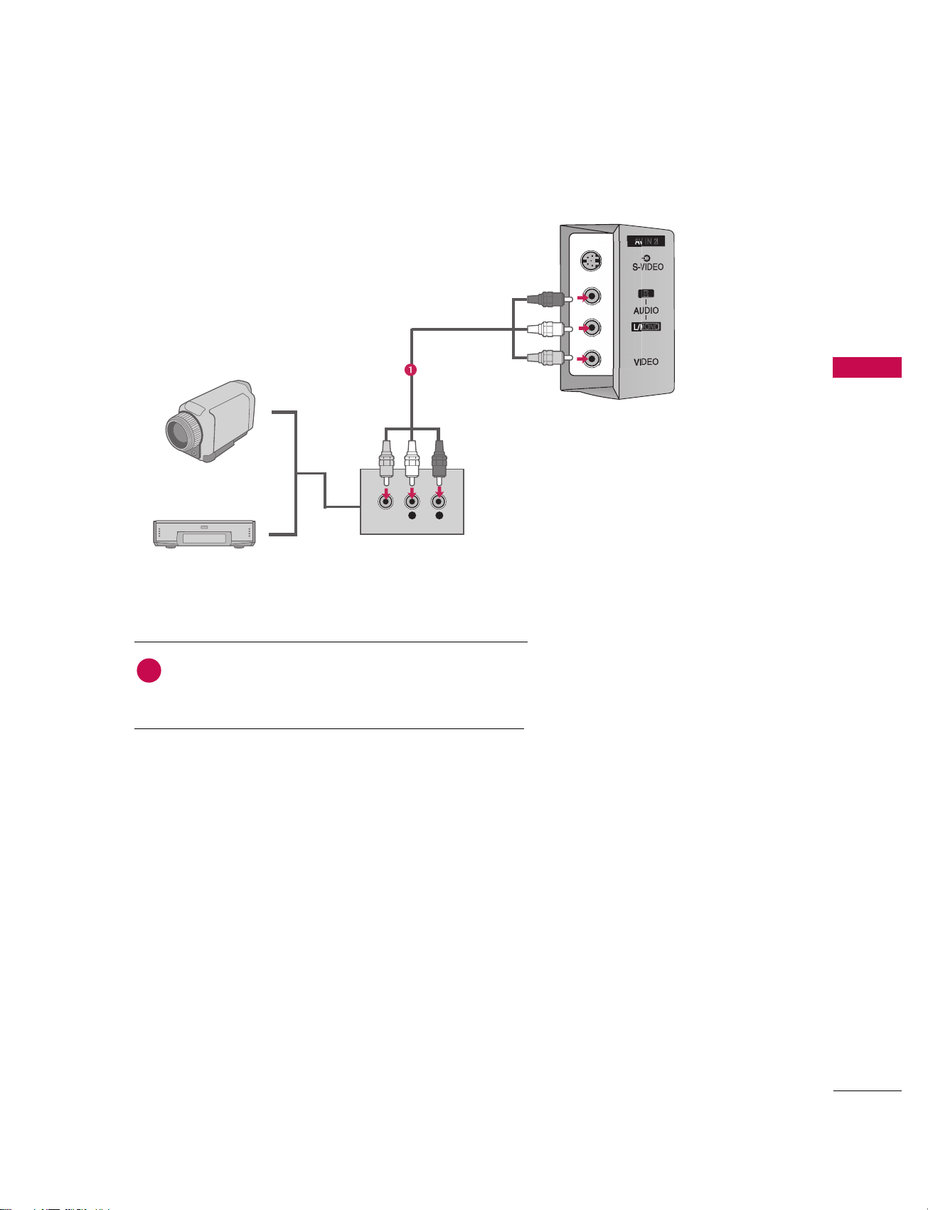
EXTERNAL A/V SOURCE SETUP
Camcorder
Video Game Set
Connect the AAUUDDIIOO/VVIIDDEEOO jacks between TV and
external equipment. Match the jack colors
.
(
Video = yellow, Audio Left = white, and Audio Right = red
)
1. How to connect
2. How to use
■
Select AAVV11 input source with using the IINNPPUUTT button on
the remote control.
■
If connected to AAVV IINN 22 input, select AAVV22 input source.
■
Operate the corresponding external equipment.
1
L R
VIDEO
CONNECTIONS & SETUP
28
AV OUT SETUP
The TV has a special signal output capability which allows you to hook up the second TV or monitor.
CONNECTIONS & SETUP
L R
S-VIDEOVIDEO
VIDEO
AUDIO
(
MONO
)
S-VIDEO
AV OUTAV OUT
Connect the second TV or monitor to the
TV’s AAVV OOUUTT jacks.
See the Operating Manual of the second TV or monitor
for further details regarding that device’s input settings.
1. How to connect
Component1-2,RGB-PC/RGB-DTV, HDMI1/DVI, HDMI2,
DTV input sources cannot be used for AV out.
We recommend to use the AV OUT jacks for VCR recording.
NOTE
2
1
CONNECTIONS & SETUP
29
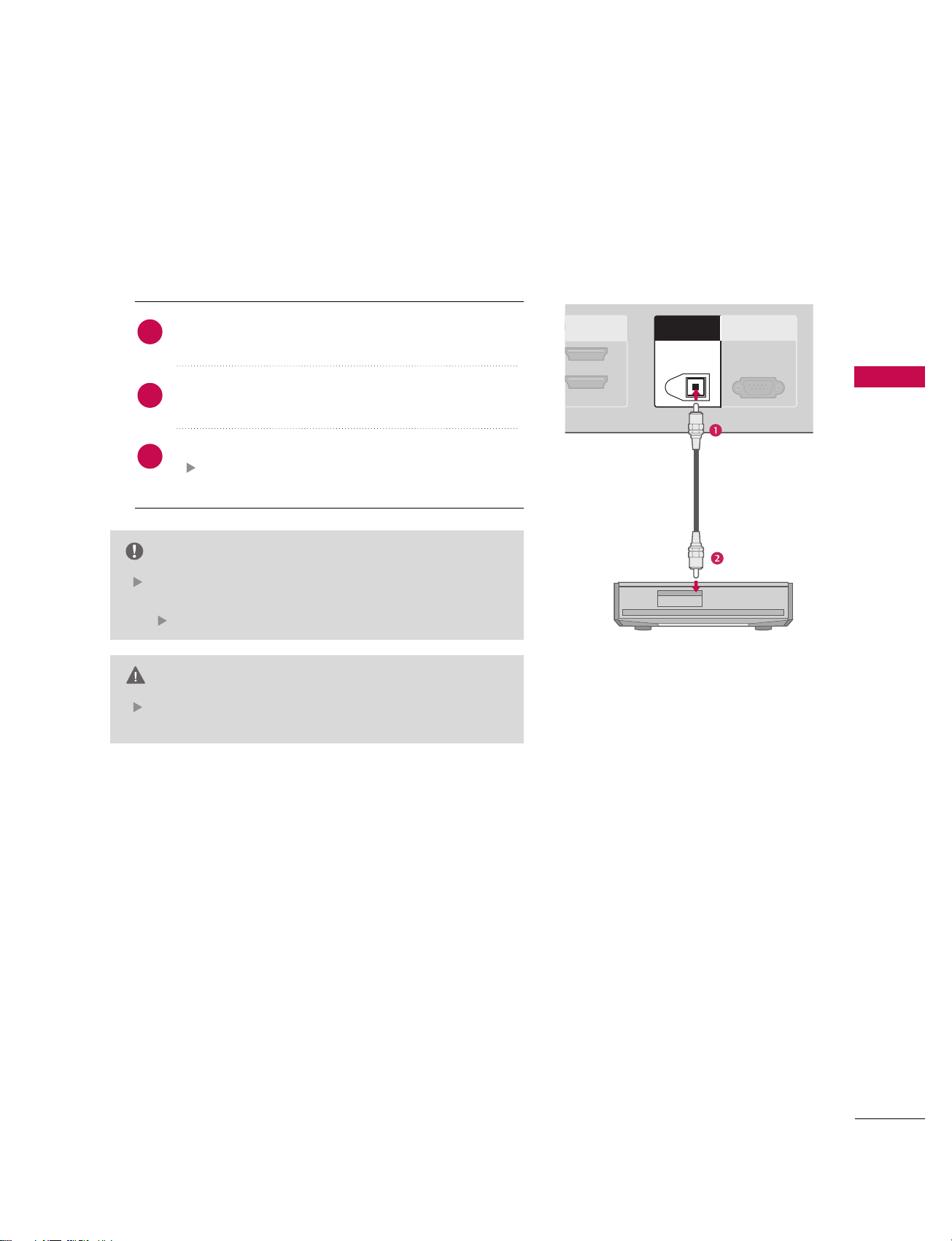
DIGITAL AUDIO OUTPUT
Send the TV’s audio to external audio equipment via the Digital Audio Output (Optical)port.
When connecting with external audio equipments, such
as amplifers or speakers, please turn the TV speakers off.
(
pp..110055)
NOTE
Do not look into the optical output port. Looking at the
laser beam may damage your vision.
CAUTION
2
1(DVI)
RS-232C IN
(CONTROL & SERVICE)
ANTENNA
IN
CABLE
IN
DIGITAL AUDIO DIGITAL AUDIO
OUTOUT
OPTICALPTICAL
Connect one end of an optical cable to the TV Digital
Audio (Optical)Output port.
Connect the other end of the optical cable to the digital audio (optical)input on the audio equipment.
Set the “TV Speaker option - Off ” in the AUDIO menu.
(
pp..110055). See the external audio equipment instruc-
tion manual for operation.
1. How to connect
2
3
1
 Loading...