

LG 50PC1D, 50PC1D-FC Service Manual

PLASMA TV
SERVICE MANUAL
CAUTION
BEFORE SERVICING THE CHASSIS,
READ THE SAFETY PRECAUTIONS IN THIS MANUAL.
CHASSIS : PD61C
MODEL : 50PC1D
50PC1D-FC
website:http://biz.LGservice.com
e-mail:http://www.LGEservice.com/techsup.html

- 2 -
CONTENTS
SAFETY PRECAUTIONS ....................................................................................3
DESCRIPTION OF CONTROLS ..........................................................................4
SPECIFICATIONS ..............................................................................................10
ADJUSTMENT INSTRUCTIONS .......................................................................12
TROUBLE SHOOTING GUIDE..........................................................................17
PRINTED CIRCUIT DIAGRAM ..........................................................................22
BLOCK DIAGRAM.............................................................................................26
EXPLODED VIEW..............................................................................................28
EXPLODED VIEW PARTS LIST ........................................................................29
REPLACEMENT PARTS LIST...........................................................................30
SCHEMATIC DIAGRAM.........................................................................................
- 3 -
SAFETY PRECAUTIONS
Many electrical and mechanical parts in this chassis have special safety-related characteristics. These parts are identified by in the
Schematic Diagram and Replacement Parts List.
It is essential that these special safety parts should be replaced with the same components as recommended in this manual to prevent
X-RADIATION, Shock, Fire, or other Hazards.
Do not modify the original design without permission of manufacturer.
General Guidance
An isolation Transformer should always be used during the
servicing of a receiver whose chassis is not isolated from the AC
power line. Use a transformer of adequate power rating as this
protects the technician from accidents resulting in personal injury
from electrical shocks.
It will also protect the receiver and it's components from being
damaged by accidental shorts of the circuitry that may be
inadvertently introduced during the service operation.
If any fuse (or Fusible Resistor) in this monitor is blown, replace it
with the specified.
When replacing a high wattage resistor (Oxide Metal Film Resistor,
over 1W), keep the resistor 10mm away from PCB.
Keep wires away from high voltage or high temperature parts.
Due to high vacuum and large surface area of picture tube,
extreme care should be used in handling the Picture Tube.
Do not lift the Picture tube by it's Neck.
Leakage Current Cold Check(Antenna Cold Check)
With the instrument AC plug removed from AC source, connect an
electrical jumper across the two AC plug prongs. Place the AC
switch in the on position, connect one lead of ohm-meter to the AC
plug prongs tied together and touch other ohm-meter lead in turn to
each exposed metallic parts such as antenna terminals, phone
jacks, etc.
If the exposed metallic part has a return path to the chassis, the
measured resistance should be between 1MΩ and 5.2MΩ.
When the exposed metal has no return path to the chassis the
reading must be infinite.
An other abnormality exists that must be corrected before the
receiver is returned to the customer.
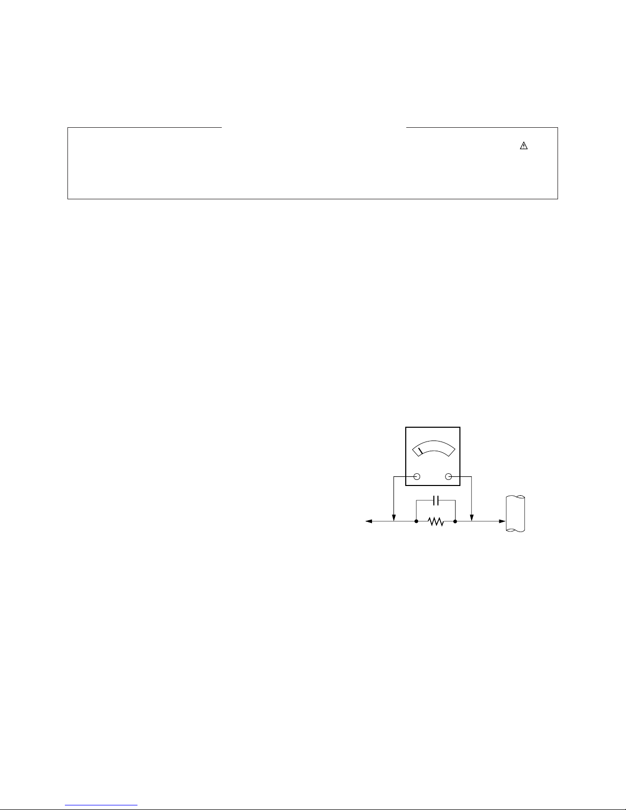
Leakage Current Hot Check
(See below Figure)
Plug the AC cord directly into the AC outlet.
Do not use a line Isolation Transformer during this check.
Connect 1.5K/10watt resistor in parallel with a 0.15uF capacitor
between a known good earth ground (Water Pipe, Conduit, etc.)
and the exposed metallic parts.
Measure the AC voltage across the resistor using AC voltmeter
with 1000 ohms/volt or more sensitivity.
Reverse plug the AC cord into the AC outlet and repeat AC voltage
measurements for each exposed metallic part. Any voltage
measured must not exceed 0.75 volt RMS which is corresponds to
0.5mA.
In case any measurement is out of the limits specified, there is
possibility of shock hazard and the set must be checked and
repaired before it is returned to the customer.
Leakage Current Hot Check circuit
1.5 Kohm/10W
To Instrument's
exposed
METALLIC PARTS
Good Earth Ground
such as WATER PIPE,
CONDUIT etc.
AC Volt-meter
IMPORTANT SAFETY NOTICE
0.15uF
POWER
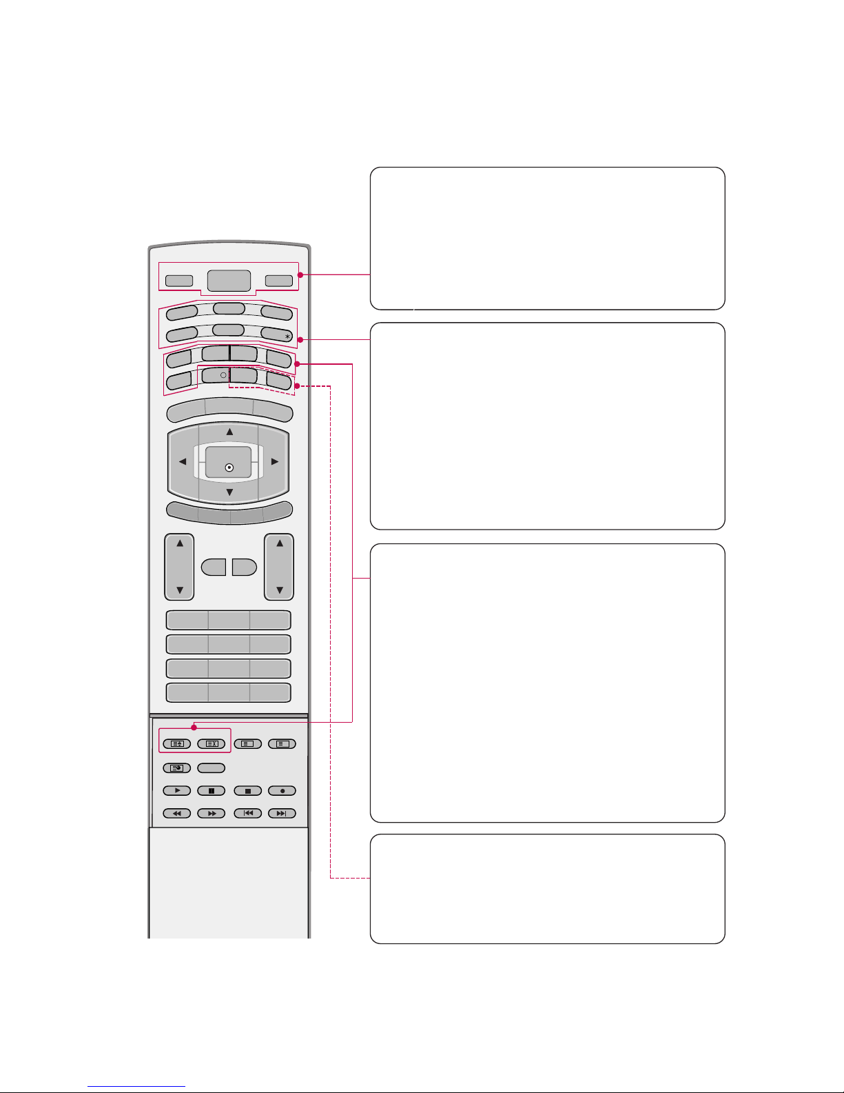
Switches the set between ON and STANDBY.
D/A TV
INPUT
VOL
LIST
Q.VIEW
PR
POWER
1 2 3
4 5 6
7809
INDEX
POSITION
SIZE
REVEAL
TIME I/II
G
U
ID
E
P
IP
P
R
-
P
IP
MENU
MUTE FAV
EXIT
VCR
T
V
DVD
ARC
TEXT
SWAP
BACK
PIP PR+
INFO
i
?
i
OK
S
U
B
T
IT
L
E
/
PIP INPUT
S
LE
E
P
D/A TV (Digital TV / Analogue TV)
Selects digital or analogue mode.
INPUT
Selects the DTV, TV, AV, Component, RGB or HDMI/DVI modes.
switches the set on from standby.
TV, DVD, VCR
Selects the remote operating mode: TV, VCR, DVD.
Select other operating modes, for the remote to operate external devices.
GUIDE
Shows programme schedule.
ARC (Aspect Ratio Control)
Selects your desired picture format.
SUBTITLE/
*
Recalls your preferred subtitle in digital mode.
PIP
Switches the sub picture on or off,select PIP, DW1/2
or POP modes.
SIZE
Adjusts the sub picture size.
POSITION
Moves the sub picture position.
PIP PR +/-
Selects a programme for the sub picture.
SWAP
Alternates between main and sub picture.
PIP INPUT
Selects the input mode for the sub picture.
BACK
Allow the user to move back one step in an interactive
application, EPG or other user interaction function.
SLEEP
Sets the sleep timer.
- 4 -
DESCRIPTION OF CONTROLS
- 5 -
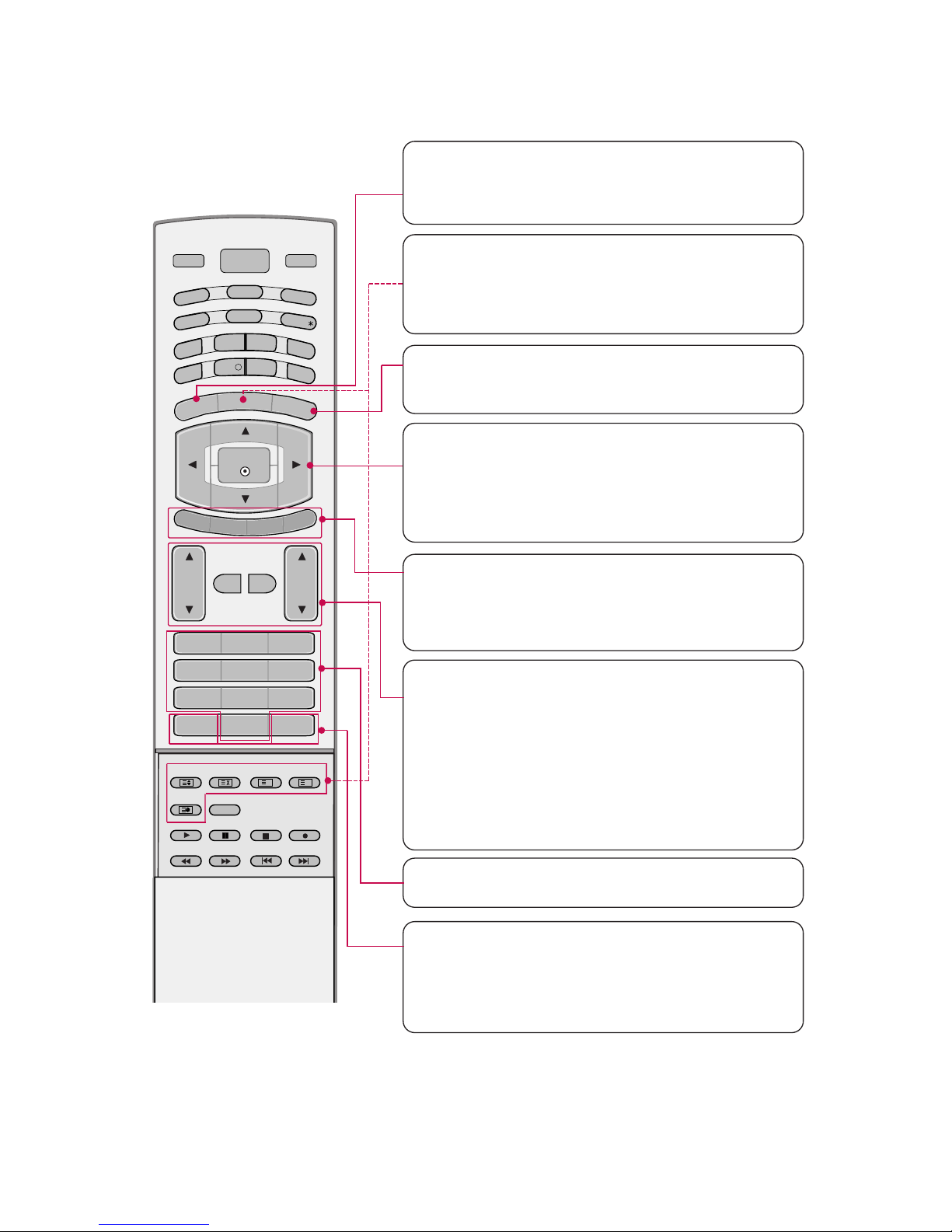
MENU
Displays on screen menus one by one.
Exits the current menu.
Memorizes menu changes.
OK
Accepts your selection or displays the current mode.
DD / EE / FF / GG
Adjusts menu settings.
Selects menu item.
COLOURED BUTTONS
They are used as per the indications or functions displayed on TV screen in case of Text displays
(Teletext, EPG) and programme edit.
VOL
DD / EE
(Volume Up/Down)
Increases/decreases sound level.
PR
DD / EE
(Programme Up/Down)
Selects a programme.
LIST
Displays the programme table.
Q.VIEW
Returns to the previously viewed programme.
NUMBER BUTTONS
MUTE
Switches the sound on or off.
FAV (FAVOURITE)
Displays the selected favourite programmes.
D/A TV
INPUT
VOL
LIST
Q.VIEW
PR
POWER
1 2 3
4 5 6
7809
INDEX
POSITION
SIZE
REVEAL
TIME I/II
G
U
ID
E
P
IP
P
R
-
P
IP
MENU
MUTE FAV
EXIT
VCR
T
V
DVD
ARC
TEXT
SWAP
BACK
PIP PR+
INFO
i
?
i
OK
S
U
B
T
IT
L
E
/
PIP INPUT
S
LE
E
P
EXIT
Clears all on-screen displays and returns to TV
viewing from any menu.
TELETEXT BUTTONS
These buttons are used for teletext.
Text button is used to enable teletext services while
other buttons are for teletext functions. * For further
details, see the ‘Teletext’ section.
- 6 -
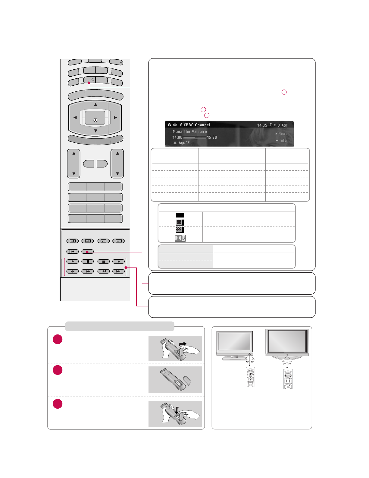
I/II
Selects the language during dual language broadcast.
Selects the sound output.
Brief Info.
What is Brief Info?
: Brief Info shows the present screen information.
:
On Watching with the upper Input signal, press the INFO i
but
ton.
How to use?
1. Press the
INFO i button to show the Brief Info on the screen.
2. Press the
INFO i button or EXIT
button to exit.
VOL
LIST
Q.VIEW
PR
1 2 3
4 5 6
7809
INDEX
POSITION
SIZE
REVEAL
TIME I/II
G
U
ID
E
P
IP
P
R
-
P
IP
MENU
MUTE FAV
EXIT
ARC
TEXT
SWAP
BACK
PIP PR+
INFO
i
?
i
OK
S
U
B
T
IT
L
E
/
PIP INPUT
S
LE
E
P
VCR/DVD BUTTONS
Controls a LG video cassette recorder.
Controls a LG DVD player.
Installing Batteries
Open the battery compartment cover on the back
side.
Insert two batteries in correct
polarity (+ with +, - with -).
Don’t mix old or used batteries with new ones.
Close the cover.
* Use a remote control 7 meter dis-
tance and 30 degree (left/right)
within the receiving unit scope.
* Dispose of used batteries in a recy-
cle bin to prevent environ
ment.
VOL
CH
POWER
MEN
U
MUTE
FAV
DAY -
GUIDE
DAY+
RAT
I
O
VCR
T
V
DVD
ENTER
PAGE
PAGE
EXI
T
T
I
M
ER
C
C
I
N
FO
AUDIO
CABLE
STB
MODE
TV INPUT
TV/VIDEO
VOL
CH
POWER
MEN
U
MUTE
FAV
DAY -
GUIDE
DAY+
RAT
I
O
VCR
T
V
DVD
ENTER
PAGE
PAGE
EXI
T
T
I
M
ER
C
C
I
N
FO
AUDIO
CABLE
STB
MODE
TV INPUT
TV/VIDEO
Remote Control Buttons
Function
F / G Change to Now/Next
D / E
The detail information on or off
1
2
3
Icon Function in Info. description Box
Teletext Programme
Subtitle Programme
Scramble Programme
Dolby Programme
TEXT
Signing SCA Correspondance
Field rating DVB
hexadecimal (decimal)
GREEN ROUND All public 0x10(16)
BLUE ROUND
Desirable parental Agreement
0x11(17)
ORANGE TRIANGLE
Prohibited at least 12 years 0x09(9)
RED SQUARE Prohibited at least 16 years 0x0D(13)
VIOLET CROSS Prohibited at least 18 years 0x0F(15)
- 7 -
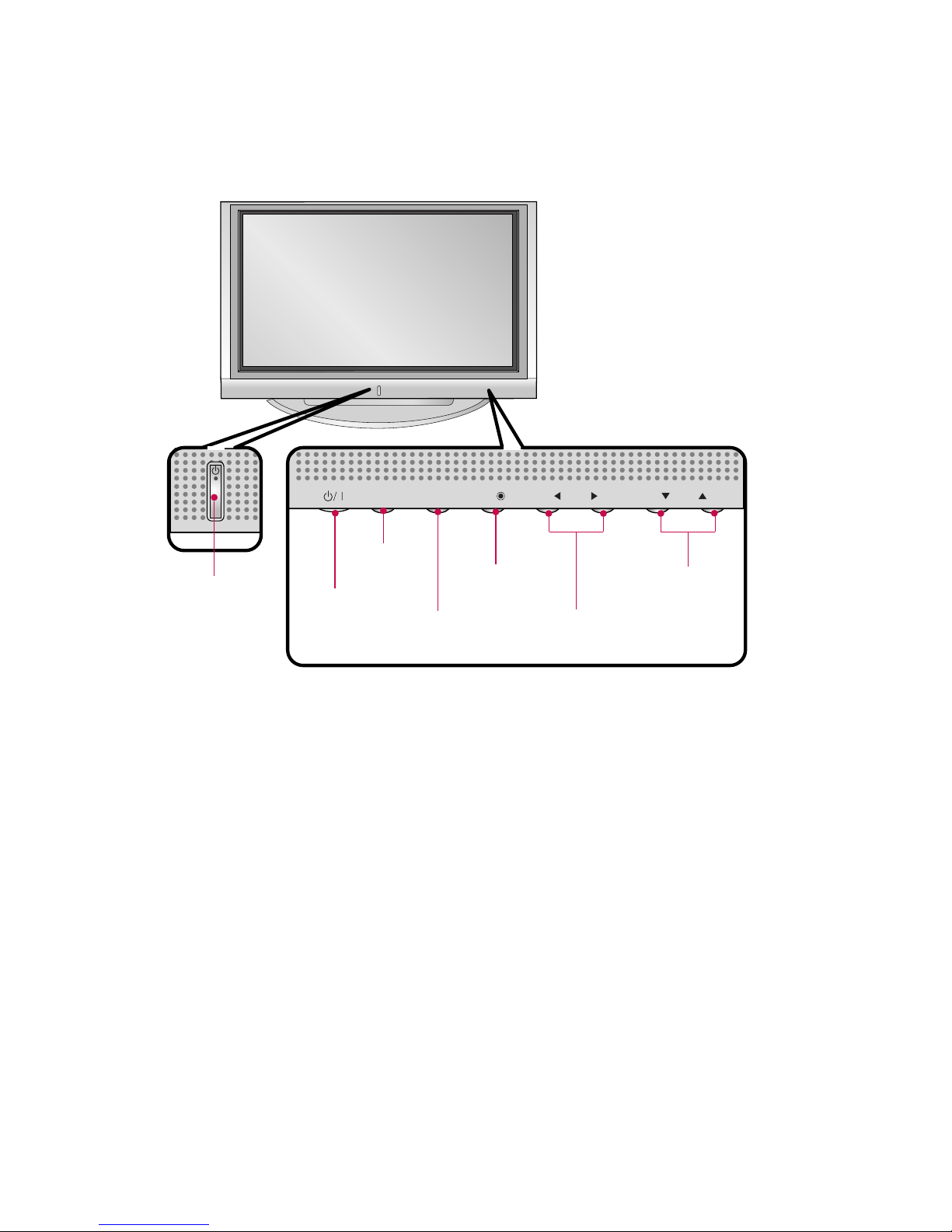
PR
VOL
OK
MENU
INPUT
PROGRAMME Buttons
VOLUME Buttons
MENU Button
OK Button
INPUT Button
POWER Button
Power/Standby Indicator
• illuminates red in
standby mode.
• illuminates white when
the set is switched on.
Front Panel Controls
- 8 -
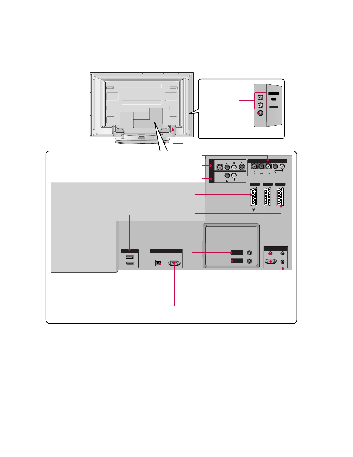
AV IN 4
L/MONOMONO
R
AUDIOAUDIO
VIDEOVIDEO
DIGITDIGITAL AUDIO
OUT
OPTICAL
1(DVI)
2
RS-232C IN
(CONTROL & SERVICE)
RGB (PC/DTV)
RGB IN
AUDIO (RGB/DVI)
IN
OUT
VIDEO
AUDIO
MONO
( )
VIDEO
AUDIO
COMPONENT IN
S-VIDEO
AV IN 3
VARIABLE
AUDIO OUT
REMOTE
CONTROL
AV 1 AV 2V 2 DTV OUT
ANTENNA
IN
ANTENNA
OUT
HDMI IN
AUDIO Input
VIDEO Input
DIGITAL AUDIO OUT
OPTICAL
AV IN 3
VARIABLE AUDIO OUT
AV 1/2
DTV OUT
COMPONENT IN
HDMI IN
- 42PC1DV models
have a unit of HDMI
input jack.
ANTENNA IN
ANTENNA OUT
AUDIO IN
(RGB/DVI)
RGB IN
(PC/DTV)
AC IN
RS-232C INPUT
(CONTROL&SERVICE)
REMOTE CONTROL Port
Back Connection Panel
- 9 -
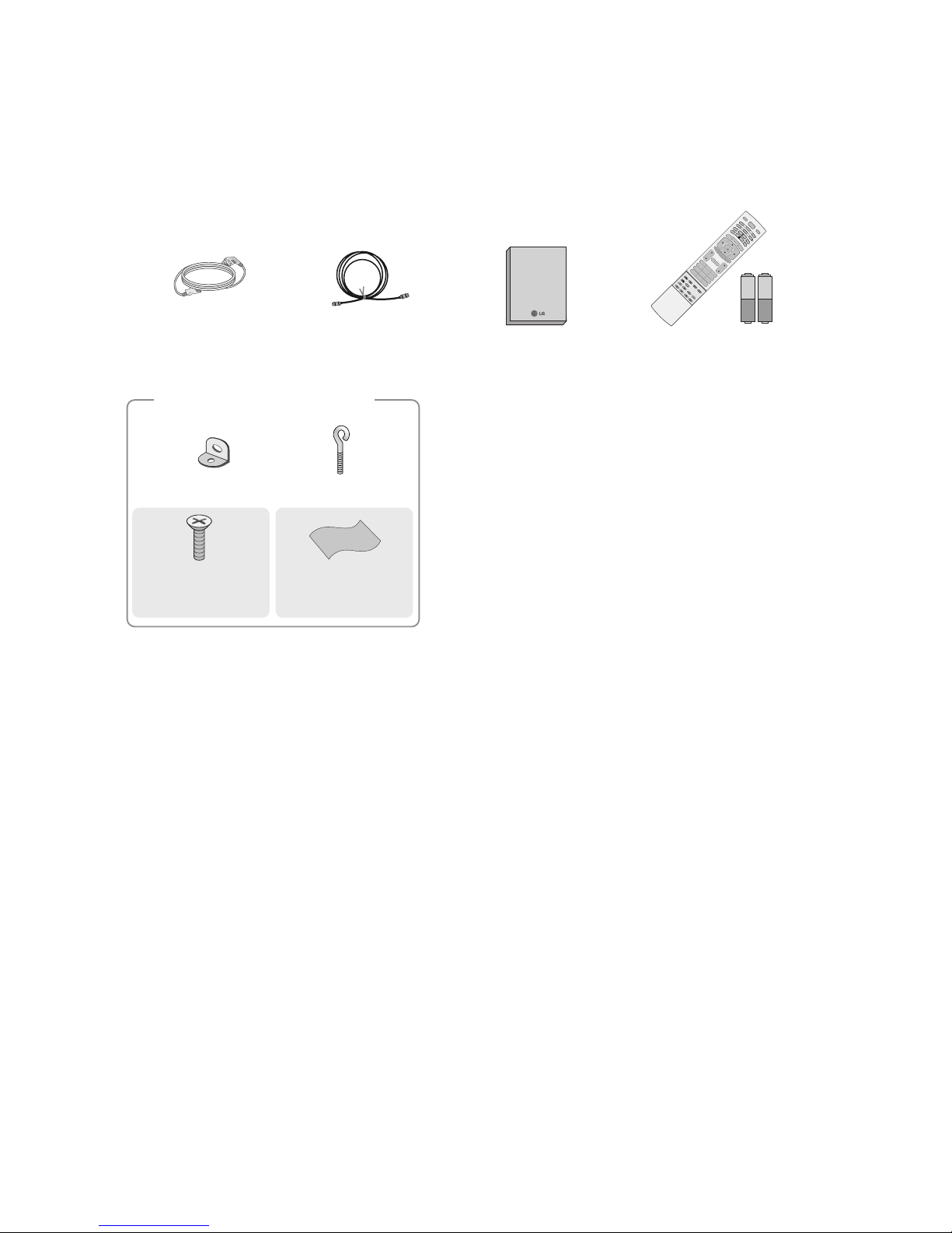
ACCESSORIES
Own er's Manual
Owner’s Manual
75Ω RF Coaxial
Power Cord
D/A TV
INPUT
VOL
LIST
Q.VIEW
PR
POWER
1 2 3
456
78
0
9
INDEX
POSITION
SIZE
REVEAL
TIME I/II
G
U
ID
E
P
I
P
P
R
-
PIP
MENU
MUTE FAV
E
X
I
T
V
C
R
T
V
DVD
ARC
TEXT
S
W
A
P
B
A
C
K
P
I
P
P
R
+
IN
F
O
i
?
i
OK
S
U
B
T
IT
L
E
/
PIP INPUT
S
L
E
E
P
D/A
VOL
LIST
Q.VIEW
PR
1 2 3
456
78
0
9
INDEX
POSITION
SIZE
REVEAL
I/II
TIME
G
U
I
D
E
P
I
P
P
R
-
PIP
MENU
MUTE FAV
E
X
IT
T
V
ARC
TEXT
S
W
A
P
B
A
C
K
P
IP
P
R
+
I
N
F
O
i
?
i
OK
S
L
E
E
P
VOL
LIST
Q.VIE
1 2 3
456
78
0
9
POSITION
SIZE
TIME
MUTE FAV
Remote Control /
Batteries
2-Wall brackets
2-eye-bolts
For 42PC1D
*,
50PC1D
*
Polishing Cloth
(42/50PC1D only)
Polish the screen
with the cloth.
2-bolts for stand assembly
(42PC1D only)
SPECIFICATIONS
NOTE : Specifications and others are subject to change without notice for improvement
.
V Application Range
This spec is applied to the 50” PLASMA TV used PD61C Chassis.
V Specification
Each part is tested as below without special appointment.
1) Temperature : 25±5°C (77±9°F), CST : 40±5
2) Relative Humidity: 65±10%
3) Power Voltage: Standard Input voltage (100-240V~, 50/60Hz)
* Standard Voltage of each product is marked by models.
4) Specification and performance of each parts are followed each drawing and specification by part number in accordance with SBOM.
5) The receiver must be operated for about 20 minutes prior to the adjustment.
V Test Method
1) Performance : LGE TV test method followed.
2) Demanded other specification
Safety : CE, IEC specification
EMC : CE, IEC
V General Specification
1. Module Specification ( 50” XGA MODULE )
- 10 -
Display Screen Device
Aspect Ratio
PDP Module
Screen Filter
Operating Environment
Storage Environment
Input Voltage
1
2
3
4
5
6
7
No Item Specification Remark
50” Wide Color Display Module
16:9
PDP50X3,
RGB Closed Type
45% Total light transmittance (E-Mesh)
1)Temp. : 0~40deg
2)Humidity : 0~80%
3)Temp. : -20~60deg
4)Humidity : 10~90%
100-240V~, 50/60H
Plasma Display Panel
Maker : NBL/ Mitsui/ LG Chemical
LGE SPEC
Maker : LG
Chassis
PD61C 50PC1D-FC France LG
Model Name Market Brand Remark
50PC1D-FC Safety : IEC/EN60065
EMI : EN55013
EMS : EN55020
France
TEST
Model ApplianceMarket Remark
- 11 -
2. Model General Specification
Market
Broadcasting system
Receiving system
Scart Jack (3EA)
Video Input (2EA)
S-Video Input (1EA)
Component Input (1EA)
RGB Input
HDMI Input(2EA)
Audio Input (4EA)
Wired Control
1
2
3
4
5
6
7
8
9
10
11
No Item Specification Remark
France
1) PAL, SECAM-BG/DK/I
2) SECAM L/L’
3) DVB-T(ID TV)
Analog : Upper Heterodyne
Digital : COFDM
PAL, SECAM
PAL, SECAM, NTSC
PAL, SECAM, NTSC
Y/Cb/Cr, Y/Pb/Pr
RGB-PC,
RGB-DTV
HDMI-PC
HDMI-DTV & SOUND
PC Audio, Component, AV (2EA)
Discrete IR
4 System : PAL, SECAM, NTSC, PAL60
4 System : PAL, SECAM, NTSC, PAL60
L/R Input
- 12 -
ADJUSTMENT INSTRUCTIONS
1. Application Object
These instructions are applied to all of the 50” PLASMA TV,
PD61C Chassis.
2. Note
(1) Because this is not a hot chassis, it is not necessary to use
an isolation transformer. However, the use of isolation
transformer will help protect test instrument.
(2) Adjustment must be done in the correct order.
(3) The adjustment must be performed in the circumstance of
25±5°C of temperature and 65±10% of relative humidity if
there is no specific designation.
(4) The input voltage of the receiver must keep 100-240V~,
50/60Hz.
(5) The receiver must be operated for about 15 minutes prior
to the adjustment.
O After RGB Full white HEAT-RUN Mode, the receiver must
be operated prior to adjustment.
O Enter into HEAT-RUN MODE
1) Press the POWER ON KEY on R/C for adjustment.
2) OSD display and screen display PATTERN MODE.
[ Set is activated HEAT-RUN without signal generator in
this mode.
[ Single color pattern(RED/BLUE/GREEN) of HEAT-RUN
mode uses to check PANEL.
Caution) If you turn on a still screen more than 20 minutes,
(Especially digital pattern, cross hatch pattern) after
image may be occur in the black level part of the screen.
3. Channel memory
3-1. Setting up the LGIDS
1) Install the LGIDS. (idsinst.exe)
2) After installation, restart your PC.
3) Extract [files.zip] to folder [c:\LGIDS\files].
4) Start LGIDS.
3-2. Channel memory Method
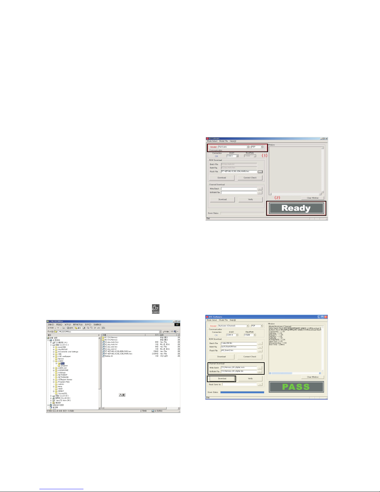
1) Select “PDP” and “Hurricane” on Model dialog. And check
your connection in Communication dialog. (If your
connection is ‘NG’, then set your PORT(COM1,2,3,...)
correctly.)
2) Connect RS-232C cable and turn on the power.
(If your connection has completed, you can see “Ready”.)
[ If your set is not an end products but only a board, you
have to make your board to Stand-by state (LED_R). And
you have to Download in Stand_by power state.
3) Select proper CH_memory file(*.nvm) for each model at
[NVRAM Download] $ [Write Batch]
Next, select proper binary file(*.bin) including the CH
information for each model at [NVRAM File].
File name : H2_CH_Memory_RZ.nvm
4) Click the [Download] button.
It means the completion of the CH memory download if all
items show ‘OK’ and Status is changed by ‘PASS’ at the
lower right corner of the window.
5) If you want to check whether the CH information is
memorized correctly or not, click the [Verify] button.
And then compare NVRAM File(*.bin) with the CH
information downloaded.
(Fig. 1)
(Fig. 2)
(1)
(2)
(4)
(3)
(Fig. 3)
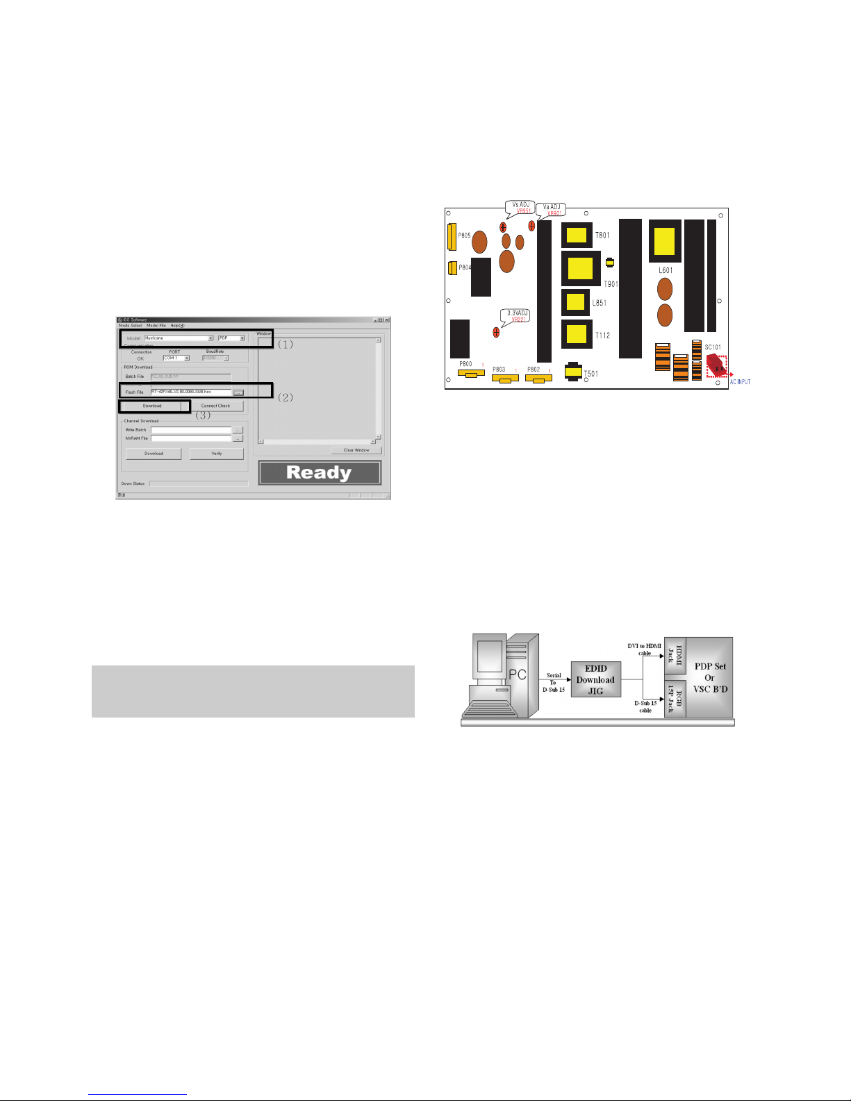
4. Sub Program Down Load
1) Select “ PDP” and “Hurricane” on Model dialog. and check
your connection in Communication dialog. (If your
connection is ‘NG’, then set your PORT(COM1,2,3,...)
correctly.
2) Connect RS232 cable and turn on the power. (Use the
special Cable for Sub-program)
(If your connection has completed, you can see ‘Ready’)
3) Select proper ‘Model’ for each model.
4) Select ‘flash file’ for each model.
5) Click the [Download] button.
It means the completion of the ROM download if all items
show ‘OK’ and Status is changed by ‘PASS’ at the lower
right corner of the window.
5. PCMCIA CARD Checking Method
1) You must adjust DTV 29 Channel and insert PCMCIA
CARD to socket.
2) If PCMCIA CARD works normally, normal signal display on
screen. But it works abnormally, “No CA module” words
display on screen.
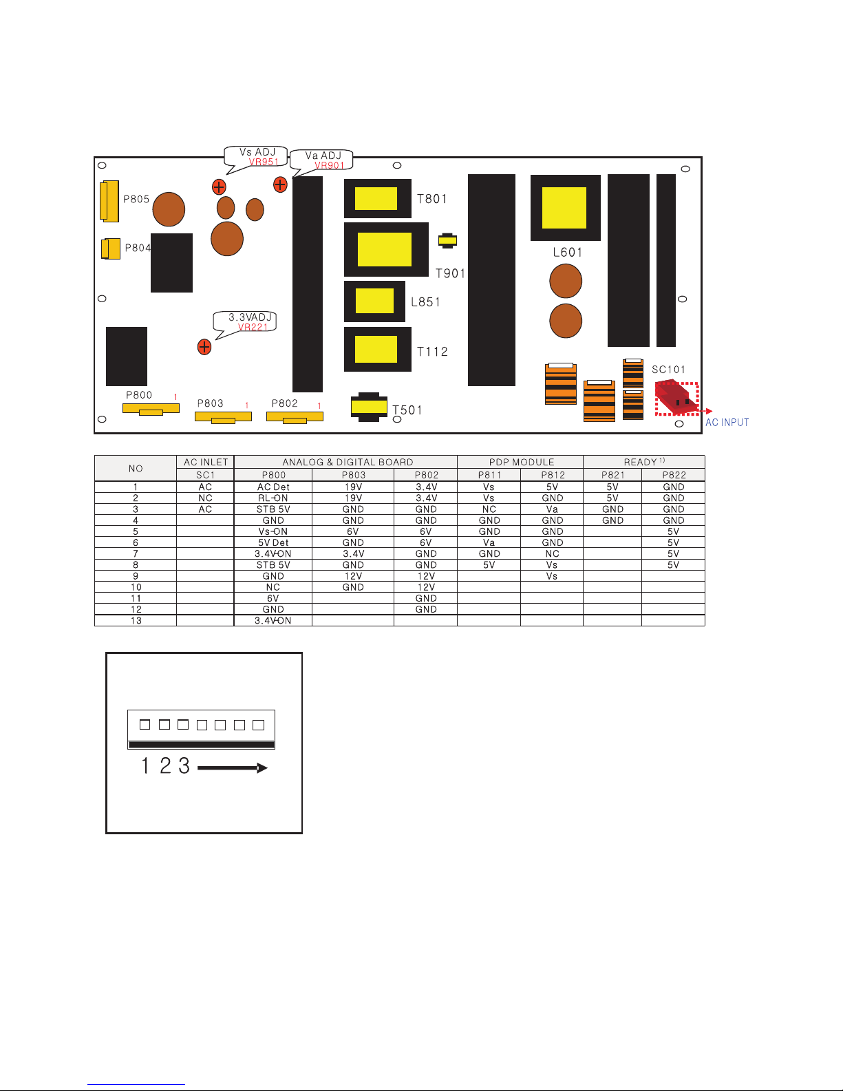
6. POWER PCB Assy Voltage
Adjustments
(Va, Vs Voltage adjustments)
6-1. Test Equipment : D.M.M. 1EA
6-2.Connection Diagram for Measuring
: refer to Fig.5
6-3. Adjustment Method
(1) Va Adjustment
1) After receiving 100% Full White Pattern, HEAT RUN.
2) Connect + terminal of D.M.M to Va pin of P805, connect
- terminal to GND pin of P805.
3) After turning VR0901, voltage of D.M.M adjustment as
same as Va voltage which on label of panel right/top.
(Deviation; ±0.5V)
(2) Vs Adjustment
1) Connect + terminal of D.M.M to Vs pin of P805, connect
– terminal to GND pin of P805.
2) After turning VR951, voltage of D.M.M adjustment as
same as Va voltage which on label of panel right/top.
(Deviation; ±0.5V)
7. EDID (The Extended Display
Identification Data)/ DDC (Display
Data Channel) download
7-1. Required Test Equipment
1) Adjusting PC with S/W for writing EDID Data.(S/W : EDID
TESTER Ver.2.5)
2) A Jig for EDID Download
3) Cable : Serial(9Pin or USB) to D-sub 15Pin cable, D-sub
15Pin cable, DVI to HDMI cable
7-2. Setting of device
7-3. Preparation for Adjustment
1) As above Fig. 6, Connect the Set, EDID Download Jig, PC
& Cable.
2) Turn on the PC & EDID Download Jig. And Execute the
S/W : EDID TESTER Ver,2.5.
3) Set up S/W option.
Repeat Number : 5
Device Address : A0
PageByte : 8
4) Power on the Set.
- 13 -
Each PCB assembly must be checked by check JIG set.
(Because power PCB Assembly damages to PDP Module,
especially be careful)
(Fig. 5) Connection diagram of power adjustment for measuring
(Fig. 6) Connection Diagram of DDC download
(1)
(2)
(3)
(Fig. 4)
- 14 -
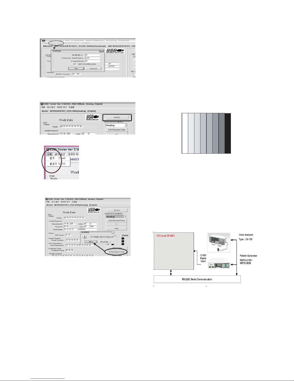
7-4. Sequence of Adjustment
- DDC data of Analog-RGB
1) Init the data.
2) Load the EDID data.(Open File).
[Analog file] (for RGB)
[Digital file] (for HDMI)
3) Set the S/W as below.
4) Push the “Write Data & Verify”button. And confirm “Yes”.
5) If the writing is finished, you will see the “OK” message.
6) If TV has two HDMI, you must download two times for
each HDMI.
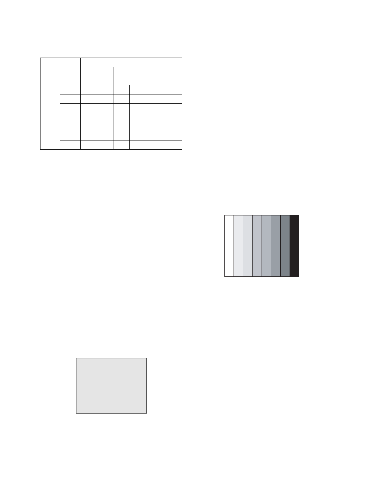
8. Auto AV(CVBS) Color Balance
8-1. Requirement
V This AV color balance adjustment should be performed
before white Balance Adjustment.
V It is very import to use adjustment pattern like Fig.7.
1) Within the pattern, color sequence should be aligned
: W-Y-C-G-M-R-BLUE-BLACK.
(If color sequence is reversed (Black -> ... -> White),
reverse the pattern with REV key, when using Master
pattern generator like MSPG-925)
2) If minimum Black level and/or maximum White level is
not correct, select 100% color bar pattern.
8-2. Required Equipment
1) Remote controller for adjustment.
2) AV Pattern Generator.
: 802F Pattern Generator, Master(MSPG-925FA), etc.
(Which has PAL Composite Video format output with
standard(1.0 Vpp) Vertical 100% Color Bar Pattern as Fig7)
8-3. Method of Auto AV(CVBS) Color Balance
1) Input the PAL Composite Video into video input.
(Input 50Hz : AV3/AV4 Input)
2) Set the PSM to Standard mode in Picture menu.
3) Press IN-STAR key on R/C for adjustment.
4) Press the
G(Vol. +) key operate to set, then it becomes
automatically.
5) Auto-RGB OK means completed adjustment.
9. Adjustment of White Balance
9-1. Required Equipment
1) Remote controller for adjustment.
2) Color Analyzer.(CA-100 or same product)
3) Auto W/B adjustment instrument.(only for Auto adjustment)
4) AV Pattern Generator.
9-2. Connecting diagram of equipment for
measuring (For Auto Adjustment)
-
Press FRONT-AV on control R/C before Automatic Adjustment.
(Fig. 7) Auto AV(CVBS) Color Balance Test Pattern
(Fig. 8) Connection Diagram of Auto W/B Adjustment
Open File
- 15 -
W Auto adjustment Map(RS-232C)
9-3. Adjustment of White Balance
(For Manual adjustment)
O Operate the zero-calibration of the CA-100, then stick
sensor to PDP module surface when you adjust.
O For manual adjustment, it is also possible by the following
sequence.
1) Select white pattern of heat-run mode by pressing power on
key on remote control for adjustment then operate heat run
more than 15 minutes.
2) As below Fig.9, Supply 216Level (85 IRE) full screen
pattern to Video input.
(Input 50Hz, 42PC1DV : AV3/AV4 Input)
3) Press the TV/AV KEY on R/C for converting input mode.
4) Set the PSM to Standard mode in Picture menu.
5) Enter the White Balance adjustment mode by pressing the
INSTART key twice(White Balance) on R/C.
6) Stick sensor to center of the screen and select each items
(Red/Green/Blue Gain and Offset) using
D / E(CH +/-) key
on R/C.
7) Adjust Only High Light with R Gain/ B Gain using
F / G
(VOL+/-) key on R/C.
8) Adjust it until color coordination becomes as below.
(Initially, R/G/B gain and R/G/B offset values are fixed as
below
Red Gain : 82, Green Gain : 80, Blue Gain : 86
Red Offset : 7F, Green Offset : 7E, Blue Offset : 82)
[PD61A]-VGA 42”, XGA 42”, 50” Module
Brightness : High Light : 60 ± 20cd/m2
Color-Coordinate : High Light : X : 0.285 ± 0.003
Y : 0.290 ± 0.003
Color Temperature : 9,300°K ± 500°K
9) When adjustment is completed, Exit adjustment mode using
EXIT key on R/C.
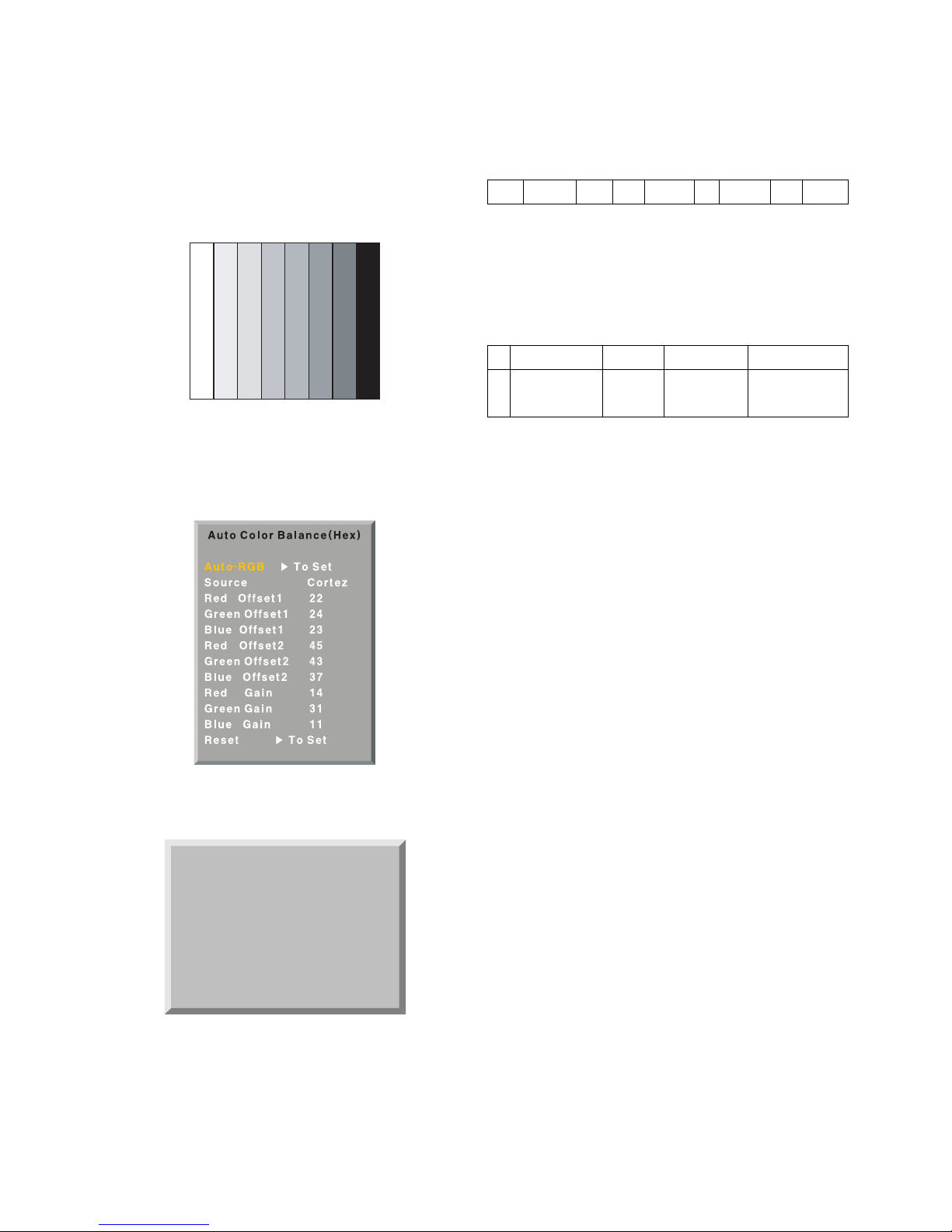
10. Auto Component Color Balance
10-1. Requirement
- It is very import to use correct adjustment pattern like Fig.10.
V Within the pattern, color sequence should be aligned
: W-Y-C-G-M-R-BLUE-BLACK.
(If color sequence is reversed(Black -> ... > White), reverse
the pattern with REV key, when using Master pattern
generator like MSPG-925)
V If Minimum Black Level and/or Maximum White Level is not
correct, select 100% Color Bar Pattern.
10-2. Required Test Equipment
1) Remote controller for adjustment.
2) 802F Pattern Generator.
(Which has 720p Ypbpr output with Standard(0.7Vpp)
Vertical 100% Color Bar Pattern as Fig.10)
10-3. Method of auto component color balance
1) Input the Component 720p 100% Color Bar signal into
Component1 or Component2.
2) Set the PSM to Standard mode in Picture menu.
3) Press INSTART key on R/C for adjustment.
4) Press the
G(Vol. +) key operate to set, then it becomes
automatically.
5) Auto-RGB OK means complete adjustment.
11. Auto RGB Color Balance
11-1. Requirement
- It is very import to use correct adjustment pattern like fig.11
V Within the pattern, color sequence should be aligned
: W-Y-C-G-M-R-BLUE-BLACK.
(If color sequence is reversed(Black -> ... > White), reverse
the pattern with REV key, when using Master pattern
generator like MSPG-925)
V If Minimum Black Level and/or Maximum White Level is not
correct, Do select 100% Color Bar Pattern.
11-2. Required Test Equipment
1) Remote controller for adjustment.
2) 802F Pattern Generator, Master(MSPG-925FA), etc.
(Which has XGA 60Hz PC Format output with standard
(0.7Vpp) 100% Color Bar Pattern as Fig.11)
(Fig. 10) Auto Component Color Balance Test Pattern
(Fig. 9) Pattern for Adjustment of White Balance
216 Level (85 IRE)216 Level (85 IRE)
Type
Baud Rate
115200
Index
R Gain
G Gain
B Gain
R Offset
G Offset
B Offset
Data bit
8
Cmd1 Cmd2
ja
jb
jc
jd
je
jf
Stop bit
1
Parity
NONE
PD61A/C
Protocol
Setting
Data Min Value
00(00)
00(00)
00(00)
00(00)
00(00)
00(00)
Max Value
255(FF)
255(FF)
255(FF)
255(FF)
255(FF)
255(FF)
- 16 -
11-3. Method of Auto RGB Color Balance
1) Input the PC 1024x768 60Hz 100%Color bar into RGB.
2) Set the PSM to Standard mode in Picture menu.
3) Press ADJ key on R/C for adjustment.
4) Press the
G(Vol. +) key operate To set, then it becomes
automatically.
5) Auto-RGB OK means completed adjustment.
12. Default value in adjustment mode
12-1. Auto Color Balance (Component/RGB)
12-2. White Balance
13. EEPROM Data Write
13-1. Signal TABLE
CMD : A0h
LENGTH : 85~94h (1~16 bytes)
ADH : E2PROM Sub Address high (00~1F)
ADL : E2PROM Sub Address low (00~FF)
Data : Write data
CS :
CMD + LENGTH + ADH + ADL + Data_1 + ... + Data_n
Delay : 20ms
13-2. Command Set
* Description
FOS Default write : <7mode data> write
Vtotal, V_Frequency, Sync_Polarity, Htotal, Hstart, Vstart, 0, Phase
Data write : Model Name and Serial Number write in EEPROM,.
13-3. Method & Notice
1) Serial number D/L is using of scan equipment.
2) Setting of scan equipment operated by Manufacturing
Technology Group.
3) Serial number D/L must be conformed when it is produced
in production line, because serial number D/L is mandatory
by D-book 4.0.
(Fig. 13) Default Value on OSD
(Fig. 12) Default Value on OSD
White Balance(Hex)
Red Gain 82
Red Offset 80
Green Gain 86
Green Offset 7F
Blue Gain 7E
Blue Offset 82
Reset G To Set
(Fig. 11) Auto RGB Color Balance Test Pattern
CMD
LENGTH
ADH ADL
DATA_1 DATA_N
... CS DELAY
No
1
EEPROM WRITE
A0h 84h+n n-byted Write
(n=1~16)
Adjust mode CMD(hex) LENGTH(hex) Description
- 17 -
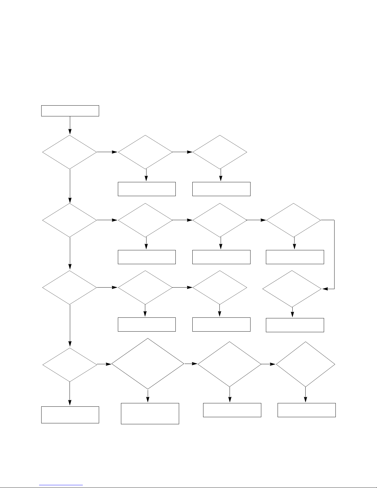
TROUBLE SHOOTING GUIDE
1. Power Board
1-1. The whole flowchart which it follows in voltage output state
Start check
Manufacture enterprise
meaning of a passage
1. Check the Power Off
condition.
Doesn't the
screen whole come
out?
Is it identical
with Power Off
condition?
Yes
Yes
No
No
No
No
No
2. Check the Interface
signal condition.
Is the Interface
signal operated?
Yes
3. Check the St-by 5V
signal circuit.
Doesn't the
low pressure output
come out?
Doesn't the
St-by 5V signal
come out?
Yes
Yes
No
4. Check the 5V Monitor
signal circuit.
Doesn't the
5V Monitor signal
come out?
Yes
7. Check the VSC Vs-ON
signal
Doesn't the
high tension output
come out?
Doesn't the
VSC signal Vs-ON
come out?
Yes
Yes
Does
high tension
output voltage Drop
occur?
When the
Y B/D Module
input connector is
removed, does output
voltage drop
occur?
When the
Y, Z B/D Module
input connector is remove,
does Power Board hightension
output voltage Drop
occur?
Yes No No
9. Check the Power
Board Output high
tension circuit
Yes
10. Check the Z B/D
Module output circuit
Yes
When the
Z B/D Module
input connector is
removed, does output
voltage Drop
occurs?
11. Check the Y B/D
Module output circuit
Yes
No
8. Check the Vs, Va
voltage output circuit.
Doesn't the
Vs, Va voltage output
come out?
Yes
No
No
5. Check the VSC RL-ON
signal.
Doesn't the
VSC signal RL-ON
come out?
Yes
6. Check the VSC low
pressure output
Doesn't the
VSC low pressure
output come out?
Yes
- 18 -
1-2. 50” Power Board Structure
T801: Vs Trans
T901: Va Trans
T902: Vs aux. Trans
L851: Vs Inductor
T112: Low Voltage Trans
T501: ST-BY Trans
T601: PFC Inductor
 Loading...