

LG 26LC5 Series, 32LC52, 26LC4 Series, 32LC4 Series, 32LC5 Series Owner's Manual
...
Please read this manual carefully before operating
your set.
Retain it for future reference.
Record model number and serial number of the set.
See the label attached on the back cover and quote
this information to your dealer when you require
service.
LCD TV PLASMA TV
OWNER’S MANUAL
LCD TV MODELS
2266LLCC44**2266LLCC55
**
3322LLCC44**3322LLCC55
**
3377LLCC44**3377LLCC55
**
4422LLCC44**4422LLCC55
**
PLASMA TV MODELS
4422 PPCC55
**
5500 PPCC55
**
5500PPBB6655
**
ENGLISH
Trade Mark of the DVB Digital Video
Broadcasting Project (1991 to 1996)
IIDD NNuummbbeerr((ss)) ::
4550: 26LC45 4549: 26LC46
4548: 32LC 45 4547: 32 LC 46
4546: 37LC45 4545: 37LC46
4544: 42LC45 4543: 42LC46
4542: 32LC55 4541: 32LC56
4540: 26LC55 4539: 37LC55
4538: 42LC55 4559: 42PC55
4555: 50PC55 4554: 42PC56
4553: 50PC56 4552: 50PB65

1
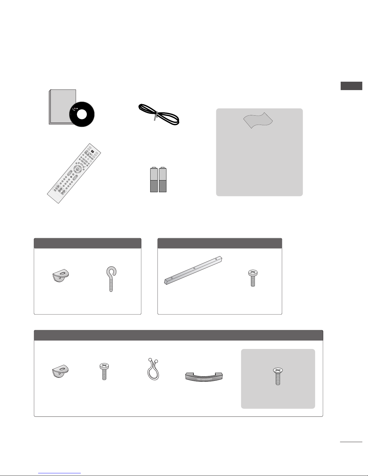
ACCESSORIES
ACCESSORIES
Ensure that the following accessories are included with your TV. If an accessory is missing, please contact the
dealer where you purchased the product.
Owner's
Manual
Owner’s manual
Owner’s Manual
Batteries
OK
INPUT
MODE
TV
D/A
DVD
EX
IT
VOL PR
GUIDE
B
A
C
K
MENU
RATIO
I/II
VCR
POWER
123
456
789
0
Q.VIEW
LIST
INDEX
S
LE
E
P
HOLD
R
E
V
E
A
L
?
SUBTITLE
TEXT
INPUT
BRIGHT
MUTE
TV/RADIO
UPDATE
SIMPLINK
INFO i
FAV
TIM
E
Remote Control
Power Cord
Cable Management
2- TV Brackets
2- Wall Brackets
2-bolts
Twister Holder
Arrange the wires
with the twister
holder.
LLCCDD TTVV mmooddeellss
PPllaassmmaa TTVV mmooddeellss
4-bolts for stand assembly
Refer to p. 8
22 66 ””,, 3322 ”” ,, 3377”” oo nnllyy
2-Wall brackets
2-eye-bolts
5500PPBB6655**oonnllyy
Polishing Cloth
(except 26/32LC4*)
Polish the screen with the cloth.
Slightly wipe stained spot on the exterior
only with the cleansing cloths for the product exterior if there is stain or fingerprint
on surface of the exterior.
Do not wipe roughly when removing stain.
Please be cautious of that excessive power
may cause scratch or discoloration.
3-bolts
Refer to p. 12
One desk-type stand fixture
protection cover
Refer to p. 12

2
CONTENTS
ACCESSORIES
. . . . . . . . . . . . . . . . . . . . . . . . . . . . . . . . . . . . . . . . . . . . .
1
PREPARATION
Front Panel Controls . . . . . . . . . . . . . . . . . . . . . . . . 4
Back Panel Information . . . . . . . . . . . . . . . . . . . . . . 6
Stand installation . . . . . . . . . . . . . . . . . . . . . . . . . . . . 8
Attaching the TV to a wall . . . . . . . . . . . . . . . . . . . . . 9
Back Cover for Wire Arrangement . . . . . . . . . . . . . 10
Desktop Pedestal Installation . . . . . . . . . . . . . . . . . 12
Wall Mount: Horizontal installation . . . . . . . . . . . . 12
Antenna Connection . . . . . . . . . . . . . . . . . . . . . . . . 13
EXTERNAL EQUIPMENT SETUP
HD Receiver Setup . . . . . . . . . . . . . . . . . . . . . . . . 14
DVD Setup . . . . . . . . . . . . . . . . . . . . . . . . . . . . . . . . 16
Insertion of CI module . . . . . . . . . . . . . . . . . . . . . . 18
VCR Setup . . . . . . . . . . . . . . . . . . . . . . . . . . . . . . . . 19
Digital Audio Out Setup . . . . . . . . . . . . . . . . . . . . . 21
Other A/V Source Setup . . . . . . . . . . . . . . . . . . . . 22
PC Setup . . . . . . . . . . . . . . . . . . . . . . . . . . . . . . . . . 23
- Screen Setup for PC Mode . . . . . . . . . . . . . . . 26
WATCHING TV / PROGRAMME CONTROL
Remote Control Key Functions . . . . . . . . . . . . . . . 30
Turning on the TV . . . . . . . . . . . . . . . . . . . . . . . . . . 32
Programme Selection . . . . . . . . . . . . . . . . . . . . . . . 33
Volume Adjustment . . . . . . . . . . . . . . . . . . . . . . . . 33
On-Screen Menus Selection and Adjustment . . . . 34
Auto Programme Tuning (In Digital Mode) . . . . . . 35
Manual Programme Tuning (In Digital Mode) . . . . 36
Programme Edit (In Digital Mode) . . . . . . . . . . . . . 37
5V antenna Power (In Digital Mode only) . . . . . . . 39
Software Update (In Digital Mode only) . . . . . . . . 40
Diagnostics (In Digital Mode only) . . . . . . . . . . . . 41
CI Information (In Digital Mode only) . . . . . . . . . . 42
Auto Programme Tuning (In Analogue Mode) . . . . . 43
Manual Programme Tuning (In Analogue Mode)
. . . . . . . 44
Fine Tuning (In Analogue Mode) . . . . . . . . . . . . . . 45
Assigning a Station Name (In Analogue Mode)
. . . . . . 45
Programme Edit (In Analogue Mode)
. . . . . . . . . . . . . 46
Calling the Programme Table . . . . . . . . . . . . . . . . 48
Input Source Selection . . . . . . . . . . . . . . . . . . . . . 49
Index (only 50PB65*) . . . . . . . . . . . . . . . . . . . . . . .49
SIMPLINK Function . . . . . . . . . . . . . . . . . . . . . . . . 50
PICTURE CONTROL
EPG (Electronic programme guide) (In Digital Mode)
- Switch on/off EPG . . . . . . . . . . . . . . . . . . . . . 52
- Select programme . . . . . . . . . . . . . . . . . . . . . 52
-
Button function in NOW/NEXT guide mode
. . . . . 53
-
Button function in 8 days guide mode
. . . . . . . . . 53
-
Button function in date change mode
. . . . . . . . . . 53
-
Button function in extended description box
. . . . . 54
-
Button function in record/remind setting mode
. . . 54
-
Button function in timer list mode
. . . . . . . . . . . . 54
Picture Size (Aspect Ratio) Control . . . . . . . . . . . . 55
Preset Picture Settings
- Picture Mode-Preset . . . . . . . . . . . . . . . . . . . . 57
-
Auto Colour Tone Control (Warm/Medium/Cool)
. . . . .58
Manual Picture Adjustment
- Picture Mode-User option . . . . . . . . . . . . . . . . 59
- Colour Tone - User option . . . . . . . . . . . . . . . .60
XD - Picture Improvement Technology . . . . . . . . . . . . . 61
XD Demo . . . . . . . . . . . . . . . . . . . . . . . . . . . . . . . . . 62
Advanced - Cinema . . . . . . . . . . . . . . . . . . . . . . . . . 63
Advanced - Black(Darkness) Level . . . . . . . . . . . . . 64
Picture Reset . . . . . . . . . . . . . . . . . . . . . . . . . . . . . . 65
Image Sticking Minimization(ISM) Method . . . . . . . . . . 66
Low-Power Picture Mode . . . . . . . . . . . . . . . . . . . . 67
CONTENTS

3
CONTENTS
SOUND & LANGUAGE CONTROL
Auto Volume Leveler . . . . . . . . . . . . . . . . . . . . . . . . 68
Preset Sound Settings - Sound Mode . . . . . . . . . . 69
Sound Setting Adjustment - User Mode . . . . . . . . . . 70
Balance . . . . . . . . . . . . . . . . . . . . . . . . . . . . . . . . . . . 71
TV Speakers On/ Off Setup . . . . . . . . . . . . . . . . . . 72
Selecting digital audio out . . . . . . . . . . . . . . . . . . . 73
I/II
-
Stereo/Dual Reception (In Analogue Mode Only)
. . . . 74
-
NICAM Reception (In Analogue Mode Only) . . . . . . .
75
- Speaker Sound Output Selection . . . . . . . . . . 75
On-Screen Menu Language/Country Selection
. . . . . . . . 76
Language selection (In Digital Mode only) . . . . . . 77
TIME SETTING
Clock Setup . . . . . . . . . . . . . . . . . . . . . . . . . . . . . . . 78
Auto On/ Off Timer Setting . . . . . . . . . . . . . . . . . . 79
Auto Shut-off Setting . . . . . . . . . . . . . . . . . . . . . . . 80
Time zone Setup . . . . . . . . . . . . . . . . . . . . . . . . . . . 81
Sleep Timer Setting . . . . . . . . . . . . . . . . . . . . . . . . . 81
PARENTAL CONTROL / RATINGS
Set Password & Lock System . . . . . . . . . . . . . . . . . 82
Parental Control . . . . . . . . . . . . . . . . . . . . . . . . . . . 83
TELETEXT
Switch on/off . . . . . . . . . . . . . . . . . . . . . . . . . . . . . . 84
SIMPLE Text . . . . . . . . . . . . . . . . . . . . . . . . . . . . . . . 84
TOP Text . . . . . . . . . . . . . . . . . . . . . . . . . . . . . . . . . 84
FASTEXT . . . . . . . . . . . . . . . . . . . . . . . . . . . . . . . . . 85
Special Teletext Functions . . . . . . . . . . . . . . . . . . . . 85
DIGITAL TELETEXT
Teletext within Digital Service . . . . . . . . . . . . . . . 86
Teletext in Digital Service . . . . . . . . . . . . . . . . . . 86
APPENDIX
Troubleshooting . . . . . . . . . . . . . . . . . . . . . . . . . . . . 87
Maintenance . . . . . . . . . . . . . . . . . . . . . . . . . . . . . . 89
Product Specifications . . . . . . . . . . . . . . . . . . . . . . 90
Programming the Remote Control . . . . . . . . . . . . . 92
Programming Code . . . . . . . . . . . . . . . . . . . . . . . . . 92
IR Codes . . . . . . . . . . . . . . . . . . . . . . . . . . . . . . . . . 94
External Control Device Setup . . . . . . . . . . . . . . . 96

4
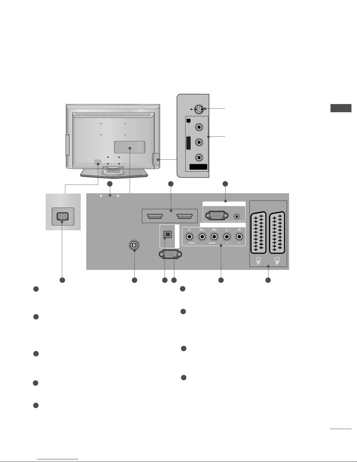
PREPARATION
FRONT PANEL CONTROLS
Plasma TV Models: 42/50PC5
*
Plasma TV Models: 50PB65
*
PREPARATION
A
This is a simplified representation of the front panel. Here shown may be somewhat different from your TV.
A
If your product has a protection film attached, remove the film and then wipe the product with a polishing
cloth.
PROGRAMME Buttons
VOLUME Buttons
MENU Button
OK Button
INPUT Button
POWER Button
PR
VOL
OK
MENU
INPUT
PROGRAMME Buttons
VOLUME Buttons
MENU Button
OK Button
INPUT Button
POWER Button
Power/Standby Indicator
• illuminates red in standby mode.
INPUT MENU OK VOL PR
Power/Standby Indicator
• illuminates red in standby mode.
• illuminates green when the set
is switched on.
Remote Control Sensor
Remote Control Sensor

5
LCD TV Models
R
Remote Control Sensor
Power/Standby Indicator
• illuminates red in standby mode.
• illuminates green when the set is switched on.
PR
VOL
OK
MENU
INPUT
/I
PROGRAMME Buttons
VOLUME Buttons
OK Button
MENU Button
INPUT Button
POWER Button
PREPARATION

6
PREPARATION
AV IN 3
L/MONO
R
AUDIO
VIDEO
S-VIDEO
Plasma TV Models
9
S-Video Input
Connect S-Video out from an
S-VIDEO device.
Audio/Video Input
Connect audio/video output
from an external device to
these jacks.
AV IN 3
L/MONO
R
AUDIOAUDIO
VIDEOVIDEO
S-VIDEO
AC IN
AV IN 3
L/MONO
R
AUDIO
VIDEO
S-VIDEO
RGB
(PC)
AUDIO
(RGB/DVI)
RGB IN
COMPONENT IN
AUDIO
VIDEO
AV 1 AV 2
EJECT
EJECT
PCMCIA
CARD SLOT
RS-232C IN
(CONTROL & SERVICE)
OPTICAL
DIGITAL AUDIO
OUT
HDMI/DVI IN
12
HDMI IN
ANTENNA
IN
1 32
PCMCIA (Personal Computer Memory Card
International Association) Card Slot
(This feature is not available in all countries.)
HDMI Input
Connect a HDMI signal to HDMI IN.
Or DVI(VIDEO)signal to HDMI/DVI port with DVI
to HDMI cable.
RGB/DVI Audio Input
Connect the monitor output from a PC to the
appropriate input port.
Antenna Input
Connect over-the-air signals to this jack.
DIGITAL AUDIO OUT OPTICAL
Connect digital audio from various types of equipment.
Note: In standby mode, these ports do not work.
RS-232C IN (CONTROL & SERVICE) PORT
Connect to the RS-232C port on a PC.
Component Input
Connect a component video/audio device to
these jacks.
Euro Scart Socket (AV1/AV2)
Connect scart socket input or output from an
external device to these jacks.
Power Cord Socket
This TV operates on an AC power. The voltage is
indicated on the Specifications page. Never
attempt to operate the TV on DC power.
1
2
3
4
5
6
7
8
9
84 5 6 7
BACK PANEL INFORMATION
PREPARATION
A
This is a simplified representation of the back panel. Here shown may be somewhat different from your TV.
7
PREPARATION
LCD TV Models
AV IN 3
L/MONO
R
AUDIO
VIDEO
S-VIDEO
AV 3
L/MONO
R
AUDIO
VIDEO
S-VIDEO
AUDIO IN
(RGB/DVI)
RGB
(PC)
RGB IN
COMPONENT IN
AUDIO
VIDEO
AV 1 AV 2
ANTENNA
IN
EJECT
EJECT
HDMI/DVI IN 1 HDMI IN 2
PCMCIA
CARD SLOT
RS-232C IN
(CONTROL & SERVICE)
OPTICAL
DIGITAL AUDIO OUT
AC-IN
AV IN 3
L/MONO
R
AUDIO
VIDEO
S-VIDEO
HDMI IN
12
RGB IN
AV 1 AV 2
ANTENNA
IN
1 2 3
9
S-Video Input
Connect S-Video out from an SVIDEO device.
Audio/Video Input
Connect audio/video output from
an external device to these jacks.
AV IN 3
L/MONO
R
AUDIOAUDIO
VIDEOVIDEO
S-VIDEO
PCMCIA (Personal Computer Memory Card
International Association) Card Slot
(This feature is not available in all countries.)
HDMI Input
Connect a HDMI signal to HDMI IN.
Or DVI(VIDEO)signal to HDMI/DVI port with DVI
to HDMI cable.
RGB/DVI Audio Input
Connect the monitor output from a PC to the
appropriate input port.
Antenna Input
Connect over-the-air signals to this jack.
DIGITAL AUDIO OUT OPTICAL
Connect digital audio from various types of equipment.
Note: In standby mode, these ports do not work.
RS-232C IN (CONTROL & SERVICE) PORT
Connect to the RS-232C port on a PC.
Component Input
Connect a component video/audio device to
these jacks.
Euro Scart Socket (AV1/AV2)
Connect scart socket input or output from an
external device to these jacks.
Power Cord Socket
This TV operates on an AC power. The voltage is
indicated on the Specifications page. Never
attempt to operate the TV on DC power.
1
2
3
4
5
6
7
8
9
84 5 6 7

8
PREPARATION
PREPARATION
STAND INSTALLATION (Only 26, 32, 37 inch LCD TV Models)
1
2
3
Carefully place the product screen side down on
a cushioned surface that will protect product and
screen from damage.
Assemble the product stand with the product as
shown.
Install the 4 bolts securely, in the back of the
product in the holes provided.
9
PREPARATION
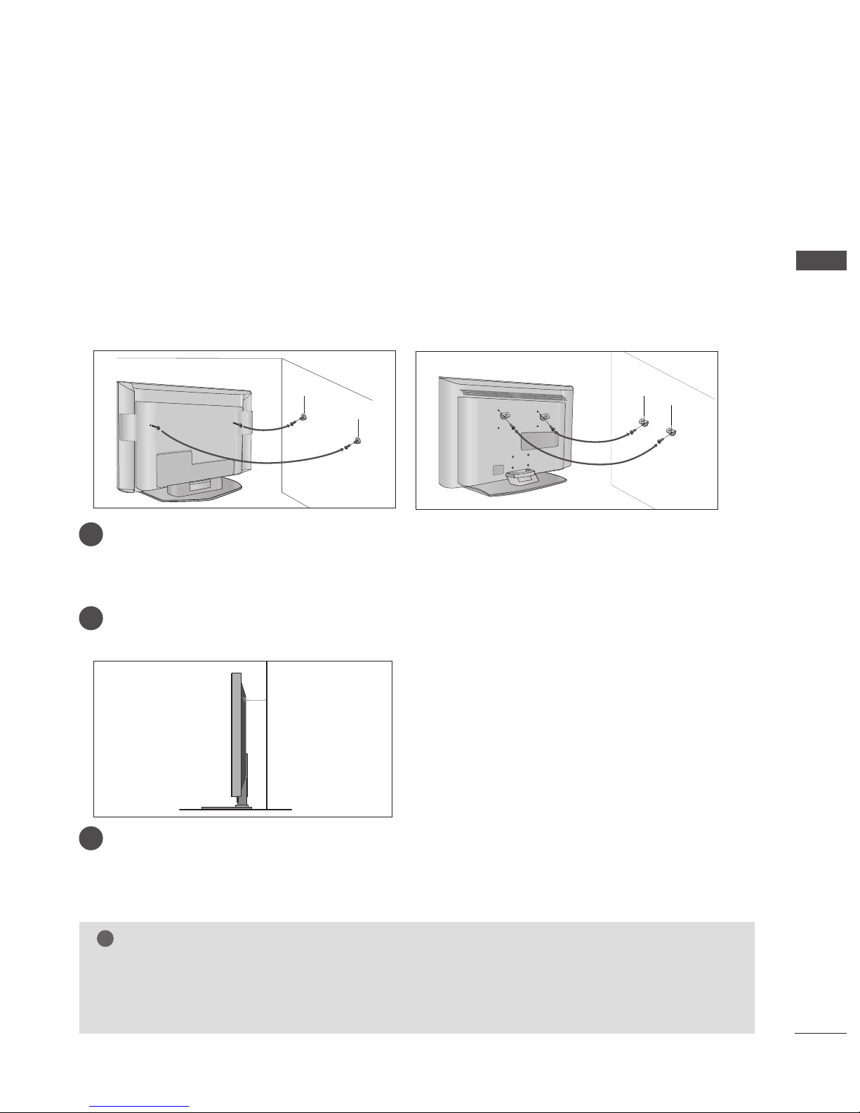
ATTACHING THE TV TO A WALL
Plasma TV models LCD TV models
2
1
A
Set it up close to the wall so the product doesn’t fall over when it is pushed backwards.
A
The instructions shown below is a safer way to set up the product, which is to fix it on the wall so the
product doesn’t fall over when it is pulled in the forward direction. It will prevent the product from
falling for-ward and hurting people. It will also prevent the product from damage caused by fall. Please
make sure that children don’t climb on or hang from the product.
NOTE
!
G
When moving the product to another place undo the ropes first.
G
Use a product holder or a cabinet that is big and strong enough for the size and weight of the product.
G
To use the product safely make sure that the height of the bracket that is mounted on the wall is same
as that of the product.
2
3
1
1
2
Use the eye-bolts or TV brackets/bolts to fix the product to the wall as shown in the picture.
(If your product has the bolts in the eye-bolts position before inserting the eye-bolts, loosen the bolts.)
* Insert the eye-bolts or TV brackets/bolts and tighten them securely in the upper holes.
Secure the wall brackets with the bolts (not provided as parts of the product, must purchase separately) on
the wall. Match the height of the bracket that is mounted on the wall.
3
Use a sturdy rope (not provided as parts of the product, must purchase separately) to tie the
product. It is safer to tie the rope so it becomes horizontal between the wall and the product.

10
PREPARATION
PREPARATION
BACK COVER FOR WIRE ARRANGEMENT
Plasma TV models
Connect the cables as necessary.
To connect an additional equipment, see the
EExxtteerr nnaall eeqquuiipp mmeenntt CCoonn nn eecctt iioonnss
section.
Reinstall the
CC AABBLLEE MMAANNAA GGEE MMEENN TT
as shown.
2
1
3
CABLE MANAGEMENT
Hold the
CC AABBLLEE MMAANNAA GGEE MMEENN TT
with hands and push it as shown.

11
PREPARATION
LCD TV models
Connect the cables as necessary.
To connect an additional equipment, see the
EExxtteerrnnaall eeqquuiippmmeenntt CCoonnnneeccttiioonnss
section.
1
Install the
CC AABBLLEE MMAANNAA GGEE MMEENN TT
as shown.
2
Bundle the cables using the supplied twister
holder.
3
Hold the
CC AABB LL EE MMAANNAAGGEE MMEE NNTT
with both
hands and pull it upward.
NOTE
!
GG
Do not hold the CABLE MANAGEMENT when moving the product.
- If the product is dropped, you may be injured or the product may be broken.
How to remove the cable management
CABLE MANAGEMENT

12
PREPARATION
PREPARATION
Desktop Pedestal Installation
R
For proper ventilation, allow a clearance of 4" on each side and from the wall.
Wall Mount: Horizontal installation
For proper ventilation, allow a clearance of 4" on each side and from the wall. Detailed installation
instructions are available from your dealer, see the optional Tilt Wall Mounting Bracket Installation and
Setup Guide.
GROUNDING
Ensure that you connect the earth ground wire to prevent
possible electric shock. If grounding methods are not possible, have a qualified electrician install a separate circuit
breaker. Do not try to ground the unit by connecting it to
telephone wires, lightening rods, or gas pipes.
Power Supply
Short-circuit
Breaker
■
The set can be installed in various ways such as on a wall, or on a desktop etc.
■
The set is designed to be mounted horizontally.
4 inches
4 inches 4 inches 4 inches
4 inches
4 inches
4 inches 4 inches
4 inches
If you want to install the desk-type stand
fixture protection cover (50PB65
*
only)
To prevent the foreign materials from
entering the desk-type stand fixture, fix
the desk-type stand fixture protection
cover by using the supplied bolts as
shown at the figure.
Bolts
Desk-type stand
fixture protection cover

13
PREPARATION
AV 3
L/ MONO
R
AUDIO
VIDEO
S-VIDEO
AUDIO
VIDEO
AV 1 AV 2
ANTENNA
IN
EJECT
HDMI/DVI IN 1 HDMI IN 2
AV 3
L/ MONO
R
AUDIO
VIDEO
S-VIDEO
AUDIO
VIDEO
AV 1 AV 2
ANTENNA
IN
EJECT
HDMI/DVI IN 1 HDMI IN 2
■
For optimum picture quality, adjust antenna direction.
■
An antenna cable and converter are not supplied.
■
To prevent the equipment damage, never plug in any power cords until you have finished connecting all equipment.
Multi-family Dwellings/Apartments
(Connect to wall antenna socket)
Single-family Dwellings /Houses
(Connect to wall jack for outdoor antenna)
Outdoor
Antenna
(VHF, UHF)
Wall
Antenna
Socket
RF Coaxial Wire (75 ohm)
ANTENNA CONNECTION
Antenna
UHF
Signal
Amplifier
VHF
■
In poor signal areas,to get better picture quality, install a signal amplifier to the antenna as shown to the right.
■
If signal needs to be split for two TVs,use an antenna signal splitter for connection.
- Be careful not to bend the bronze
wire when connecting to an antenna
port.
- 5V antenna power works In Digital
mode only. (Refer to p. 39)
AV IN 3
L/MONO
R
AUDIO
VIDEO
S-VIDEO
AV IN 3
L/MONO
R
AUDIO
VIDEO
S-VIDEO
14
EXTERNAL EQUIPMENT SETUP
EXTERNAL EQUIPMENT SETUP
HD RECEIVER SETUP
■
This TV can receive Digital Over-the-air/Cable signals without an external digital set-top box.However,if you do
receive Digital signals from a digital set-top box or other digital external device,refer to the figure as shown
below.
AUDIO IN
(RGB/DVI)
RGB
(PC)
RGB IN
COMPONENT IN
AUDIO
VIDEO
AAV 1 AV 2
DIGITAL AUDIO OUT
AUDIO
VIDEO
ANTENNA
IN
HDMI/DVI IN 1 HDMI IN 2
EJECT PCMCIA
CARD SLOT
When connecting with a component cable
Connect the video outputs (Y, PB, P
R
)
of the digital set
top box to the
CC OOMMPPOONNEENNTT IINN VVII DDEEOO
jacks on the
set.
Connect the audio output of the digital set-top box to
the
CC OOMMPPOONNEENNTT IINN AAUUDDIIOO
jacks on the set.
Turn on the digital set-top box.
(
Refer to the owner’s manual for the digital set-top box.
)
Select
COMPONENT input source with using the
IINN PP UUTT
button on the remote control.
2
3
4
1
Signal
480i/576i
480p/576p
720p/1080i
10 8 0 p
Component
Yes
Yes
Yes
No
HDMI1/2
No
Yes
Yes
Yes
1 2
■
To prevent the equipment damage, never plug in any power cords until you have finished connecting all equipment.
■
This part of EXTERNAL EQUIPMENT SETUP mainly use pictures for the LCD TV models.
15
EXTERNAL EQUIPMENT SETUP
AUD
(RG
RGB
(PC)
RGB IN
COMPONENT I
AUDIAUDIO
VIDEO
AV 1 AV 2
ANTENNA
IN
HDMI/DVI IN 1 HDMI IN 2
EJECT PCMCIA
RS-232C IN
(CONTROL & SERVICE)
OPTICAL
DIGITAL AUDIO OUT
AUDIO
VIDEO
AV 1 AV 2
ANTENNA
IN
HDMI/DVI IN 1 HDMI IN 2
EJECT PCMCIA
CARD SLOT
RS-232C IN
AUDIO
VIDEO
AV 1 AV 2
ANTENNA
IN
HDMI/DVI IN 1 HDMI IN 2
EJECT PCMCIA
CARD SLOT
RS-232C IN
AUDIO IN
(RGB/DVI)
RGB
(PC)
RGB IN
COMPONENT IN
AUDIO
VIDEO
AAV 1 AV 2
HDMI/DVI IN 1 HDMI IN 2
RS-232C IN
(CONTROL & SERVICE)
OPTICAL
DIGITAL AUDIO OUT
1
2
Connect the digital set-top box to
HHDD MMII//DDVVII II NN 11
jack on the set.
Connect the audio output of the digital set-top box to
the
AAUUDDIIOO IINN ((RR GGBB//DD VVII))
jack on the set.
Turn on the digital set-top box. (Refer to the owner’s
manual for the digital set-top box.
)
Select
HDMI1 input source with using the
IINN PPUUTT
button on the remote control.
2
3
4
1
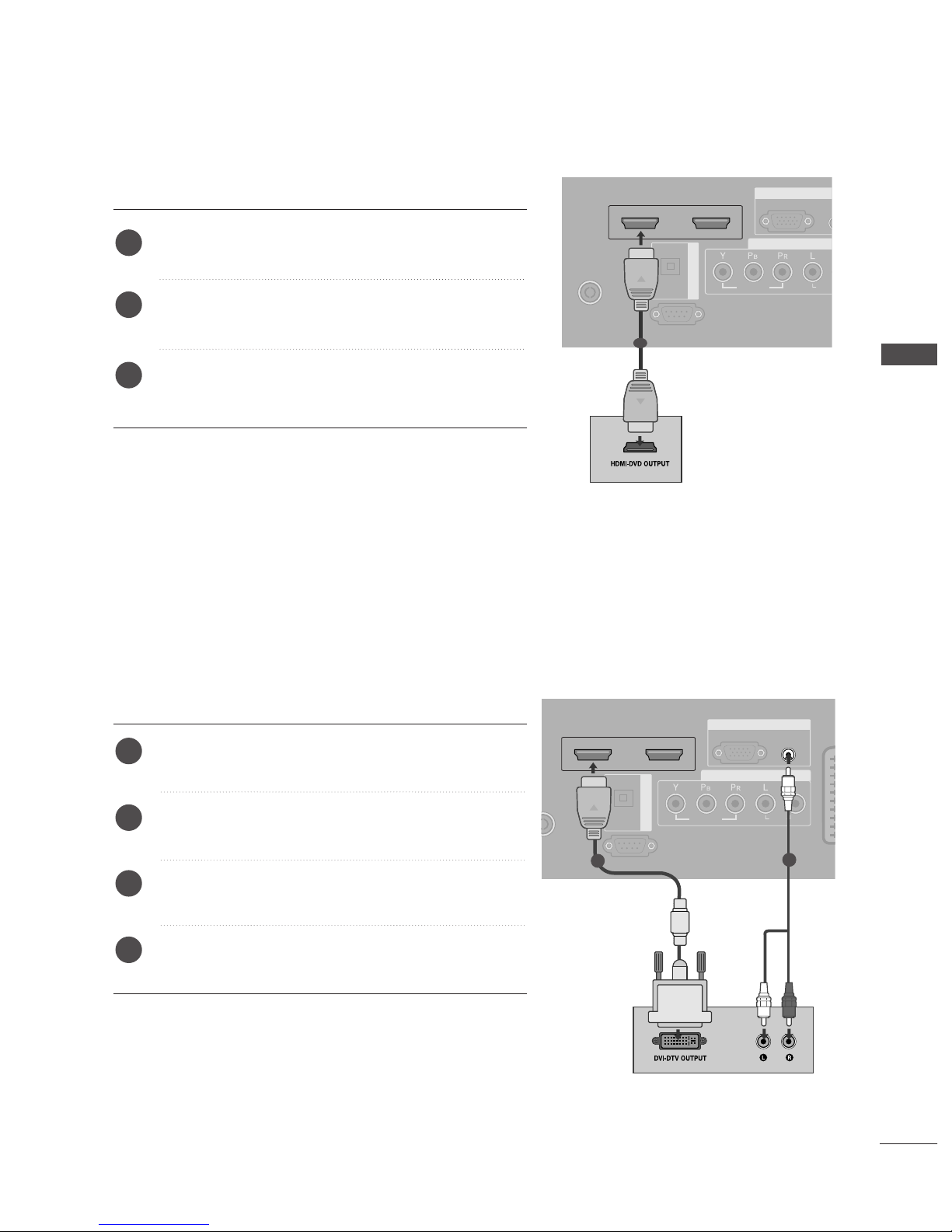
When connecting with a HDMI cable
Connect the digital set-top box to
HHDD MMII//DDVVII IINN 11
or
HHDD MMII IINN 22
jack on the set.
Turn on the digital set-top box.
(
Refer to the owner’s manual for the digital set-top box.
)
Select
HDMI1 or HDMI2 input source with using the
IINN PPUUTT
button on the remote control.
2
3
1
1
When connecting with a HDMI to DVI cable

16
EXTERNAL EQUIPMENT SETUP
EXTERNAL EQUIPMENT SETUP
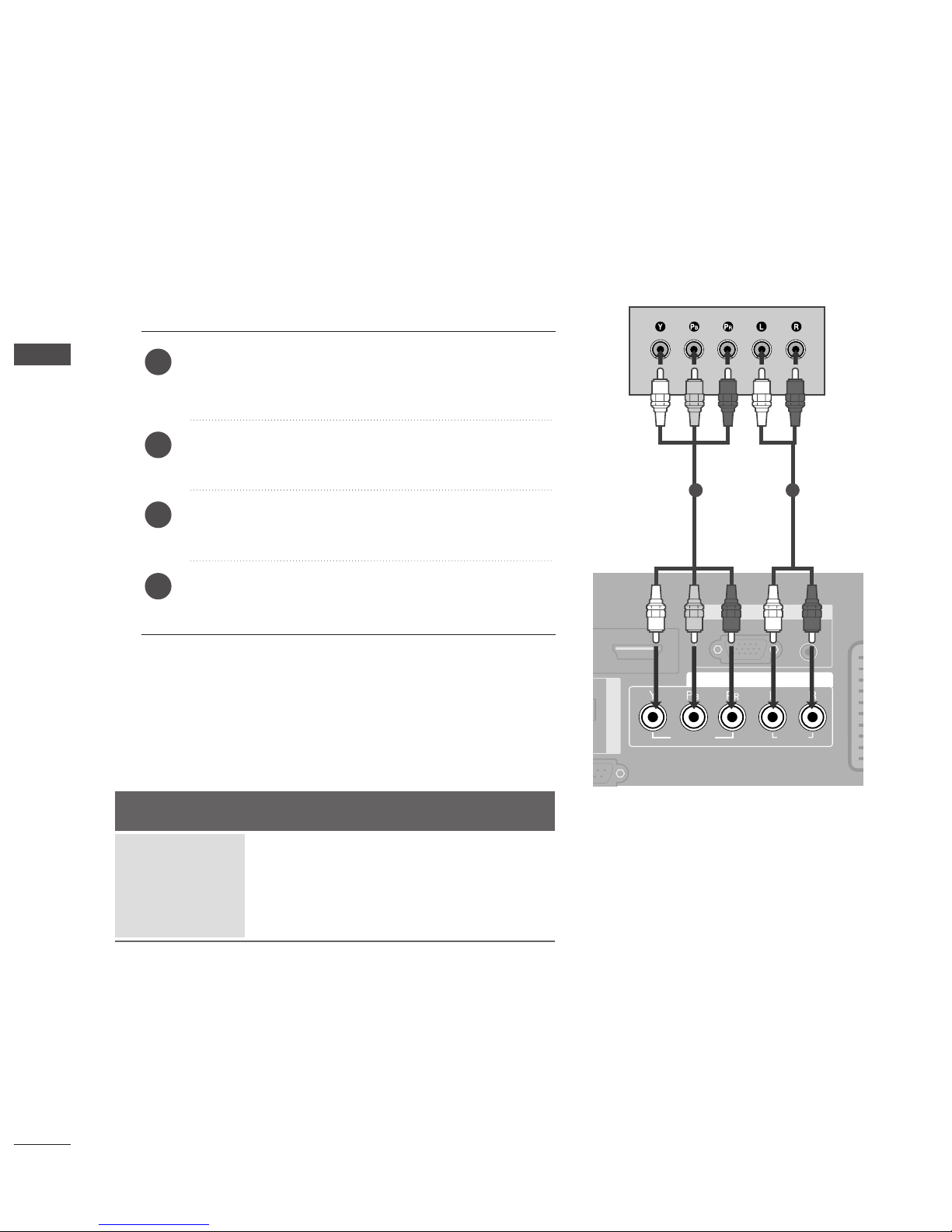
DVD SETUP
When connecting with a component cable
AUDIO IN
(RGB/DVI)
RGB
(PC)
RGB IN
COMPONENT IN
AUDIO
VIDEO
AAV 1 AV 2
DIGITAL AUDIO OUT
L/ MONO
R
AUDIO
VIDEO
S-VIDEO
Component Input ports
To get better picture quality, connect a DVD player to the component input ports as shown below.
Component ports on the TV
YPB PR
Video output ports
on DVD player
Y
Y
Y
Y
PB
B-Y
Cb
Pb
P
R
R-Y
Cr
Pr
Connect the video outputs (Y, P
B, PR
)
of the DVD to the
CC OOMMPPOONNEENNTT IINN VVII DDEEOO
jacks on the set.
Connect the audio outputs of the DVD to the
CC OOMMPPOONNEENNTT IINN AAUUDDIIOO
jacks on the set.
Turn on the DVD player, insert a DVD.
Select
COMPONENT input source with using the
IINN PPUUTT
button on the remote control.
Refer to the DVD player's manual for operating
instructions.
2
3
4
5
1
1 2

17
EXTERNAL EQUIPMENT SETUP
When connecting with a Euro Scart
Connect the Euro scart socket of the DVD to the
AAVV 11
Euro scart socket on the set.
Turn on the DVD player, insert a DVD.
Select
AV 1 input source with using the
IINN PPUUTT
button
on the remote control.
If connected to
AV 2 Euro scart socket, select AV 2
input source.
Refer to the DVD player's manual for operating
instructions.
2
3
4
1
AUDIO
VIDEO
AV 1 AV 2
ANTENNA
IN
HDMI/DVI IN 1 HDMI IN 2
EJECT PCMCIA
CARD SLOT
RS-232C IN
AV IN 3
L/ MONO
R
AUDIO
VIDEO
S-VIDEO
AUDIO IN
(RGB/DVI)
AUDIO
AV 1 AV 2
(R) AUDIO (L)
AUDIO/
VIDEO
1
NOTE
!
GG
If you want to use the EURO scart cable, you have to use
the signal shielded Euro scart cable.
When connecting with an S-Video cable
AV IN 3
L/MONO
R
AUDIOAUDIO
VIDEOVIDEO
S-VIDEO
L R
S-VIDEOVIDEO
OUTPUT
SWITCH
ANT IN
ANT OUT
Connect the S-VIDEO output of the DVD to the
SS--
VVII DDEE OO
input on the set.
Connect the audio outputs of the DVD to the
AAUU DDIIOO
input jacks on the set.
Turn on the DVD player, insert a DVD.
Select
AV 3 input source with using the
IINN PPUUTT
button
on the remote control.
Refer to the DVD player's manual for operating instructions.
2
3
4
5
1
1
2
18
EXTERNAL EQUIPMENT SETUP
EXTERNAL EQUIPMENT SETUP
RGB
(P
R
COMP
AUDIO
VIDEO
AV 1 AV 2
ANTENNA
IN
HDMI/DVI IN 1 HDMI IN 2
EJECT PCMCIA
RS-232C IN
(CONTROL & SERVICE)
OPTICAL
DIGITAL AUDIO OUT
AV IN 3
L/ MONO
R
AUDIO
VIDEO
S-VIDEO
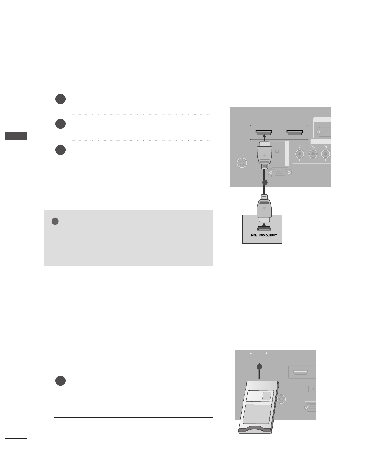
When connecting HDMI cable
Connect the HDMI output of the DVD to the
HHDDMMII//DDVVII
IINN 11
or
HHDDMMII IINN 22
jack on the set.
Select
HDMI1or HDMI2 input source with using the
IINN PPUUTT
button on the remote control.
Refer to the DVD player's manual for operating
instructions.
1
2
3
Insert the CI Module to
PPCC MMCCIIAA
(Personal Computer
Memory Card International Association)
CC AA RR DD SSLL OOTT
of TV as shown.
For further information, see p.42.
1
GG
TV can receive the video and audio signal simultaneously
with using a HDMI cable.
GG
If the DVD does not support Auto HDMI, you need to set
the output resolution appropriately.
NOTE
!
1
INSERTION OF CI MODULE
AUDIO
VIDEO
AV 1 AV 2
ANTENNAANTENNA
IN
HDMI IN 1HDMI IN 1 HDMI IN 2
EJECT PCMCIAPCMCIA
CARD SLOT
RS-232RS-232C IN
(CONTROL &
OPTICA
TVTVTV
-- TToo vviiee ww tthhee ssccrr aammbbll eedd ((ppaayy )) ss eerrvviicceess iinn dd ii ggii ttaall TTVV
mm oo dd ee..
-- TT hhii ss ffee aattuurr ee iiss nnoott aavvaa iillaabbllee iinn aallll cc oouu nn ttrr ii eess..
1
19
EXTERNAL EQUIPMENT SETUP
When connecting with an antenna
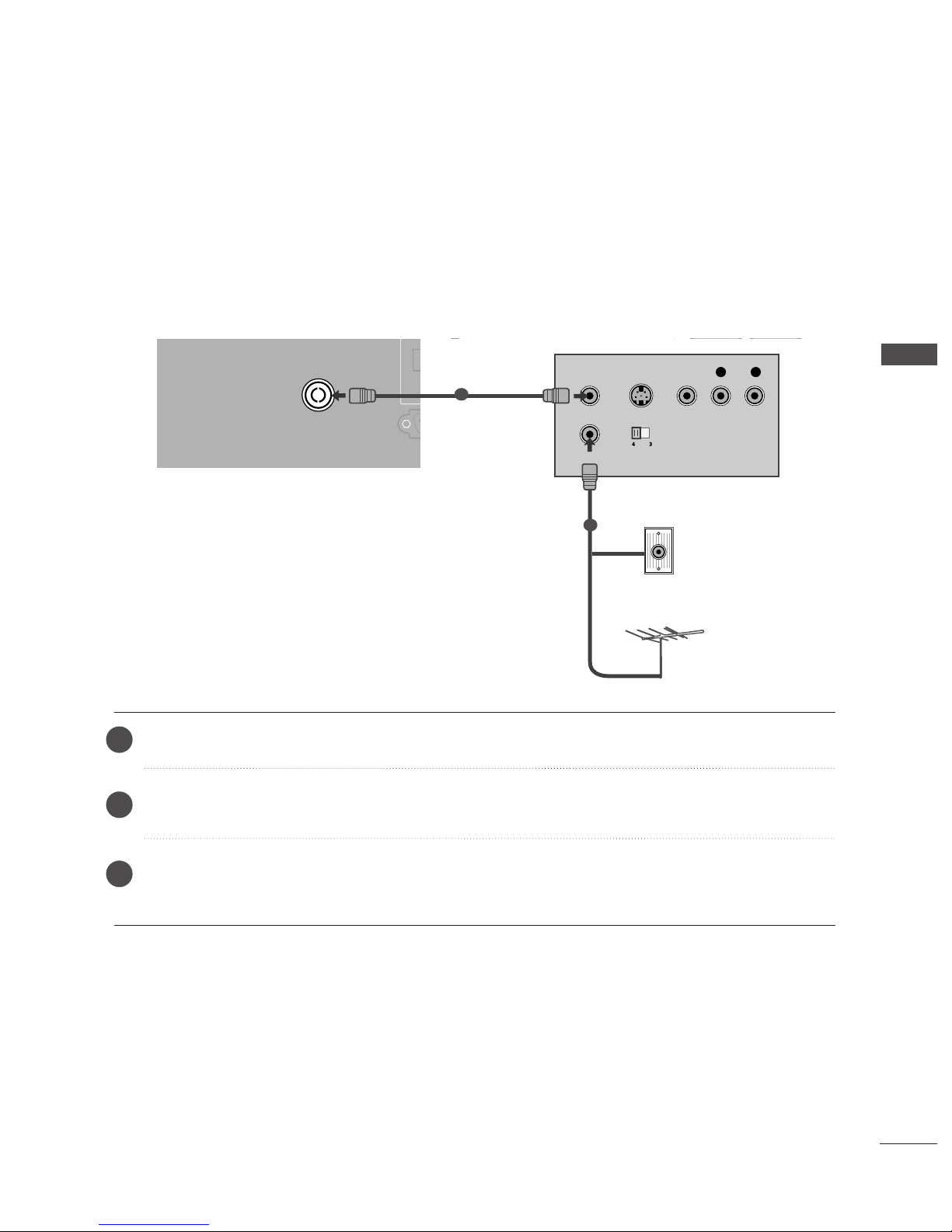
■
To avoid picture noise (interference), leave an adequate distance between the VCR and TV.
■
Typically a frozen still picture from a VCR. If the 4:3 picture format is used; the fixed images on the sides of
the screen may remain visible on the screen.
AUDIO
VIDEO
AV 1 AV 2
ANTENNA
IN
HDMI/DVI IN 1 HDMI IN 2
EJECT PCMCIA
CARD SLOT
RS-232C IN
(CONTROL & SERVICE)
OPTICAL
DIGITAL AUDIO OU
OUTPUT
SWITCH
ANT IN
R
S-VIDEO VIDEO
ANT OUT
L
Wall Jack
Antenna
Connect the
AANNTT OOUU TT
socket of the VCR to the
AANNTT EENNNN AA IINN
socket on the set.
Connect the antenna cable to the
AANNTT IINN
socket of the VCR.
Press the
PPLLAAYY
button on the VCR and match the appropriate programme between the TV and VCR for
viewing.
VCR SETUP
1
2
2
3
1

20
EXTERNAL EQUIPMENT SETUP
EXTERNAL EQUIPMENT SETUP
When connecting with a Euro Scart
Connect the Euro scart socket of the VCR to the
AAVV 11
Euro scart socket on the set.
Insert a video tape into the VCR and press PLAY on
the VCR. (Refer to the VCR owner’s manual.)
Select
AV 1 input source with using the
IINN PPUUTT
button
on the remote control.
If connected to
AAVV 22
Euro scart socket, select
AV 2
input source.
2
3
4
1
AUDIO
VIDEO
AV 1 AV 2
ANTENNA
IN
HDMI/DVI IN 1 HDMI IN 2
EJECT PCMCIA
CARD SLOT
RS-232C IN
AUDIO IN
(RGB/DVI)
(PC)
RGB IN
AUDIO
AV 1 AV 2
(R) AUDIO (L)
AUDIO/
VIDEO
AV IN 3
L/ MONO
R
AUDIO
VIDEO
S-VIDEO
AV IN 3
L/ MONO
R
AUDIO
VIDEO
S-VIDEO
1
NOTE
!
GG
If you want to use the EURO scart cable, you have to use the signal shielded Euro scart cable.
When connecting with a RCA cable
L
R
S-VIDEO
VIDEO
OUTPUT
SWITCH
ANT IN
ANT OUT
AV IN 3
L/ MONO
R
AUDIO
VIDEO
S-VIDEO
AV IN 3
L/MONO
R
AUDIOAUDIO
VIDEOVIDEO
S-VIDEO
Connect the
AAUU DDIIOO/VVIIDD EE OO
jacks between TV and
VCR. Match the jack colours (Video = yellow, Audio Left
= white, and Audio Right = red)
Insert a video tape into the VCR and press PLAY on
the VCR. (Refer to the VCR owner’s manual.
)
Select
AV 3 input source using the
IINN PPUU TT
button on
the remote control.
1
2
3
GG
If you have a mono VCR, connect the audio cable from the
VCR to the
AAUU DDII OO LL// MMOO NNOO
jack of the set.
NOTE
!
1
21
EXTERNAL EQUIPMENT SETUP
GG
If both S-VIDEO and VIDEO sockets have been connected to
the S-VHS VCR simultaneously, only the S-VIDEO can be
received.
NOTE
!
L
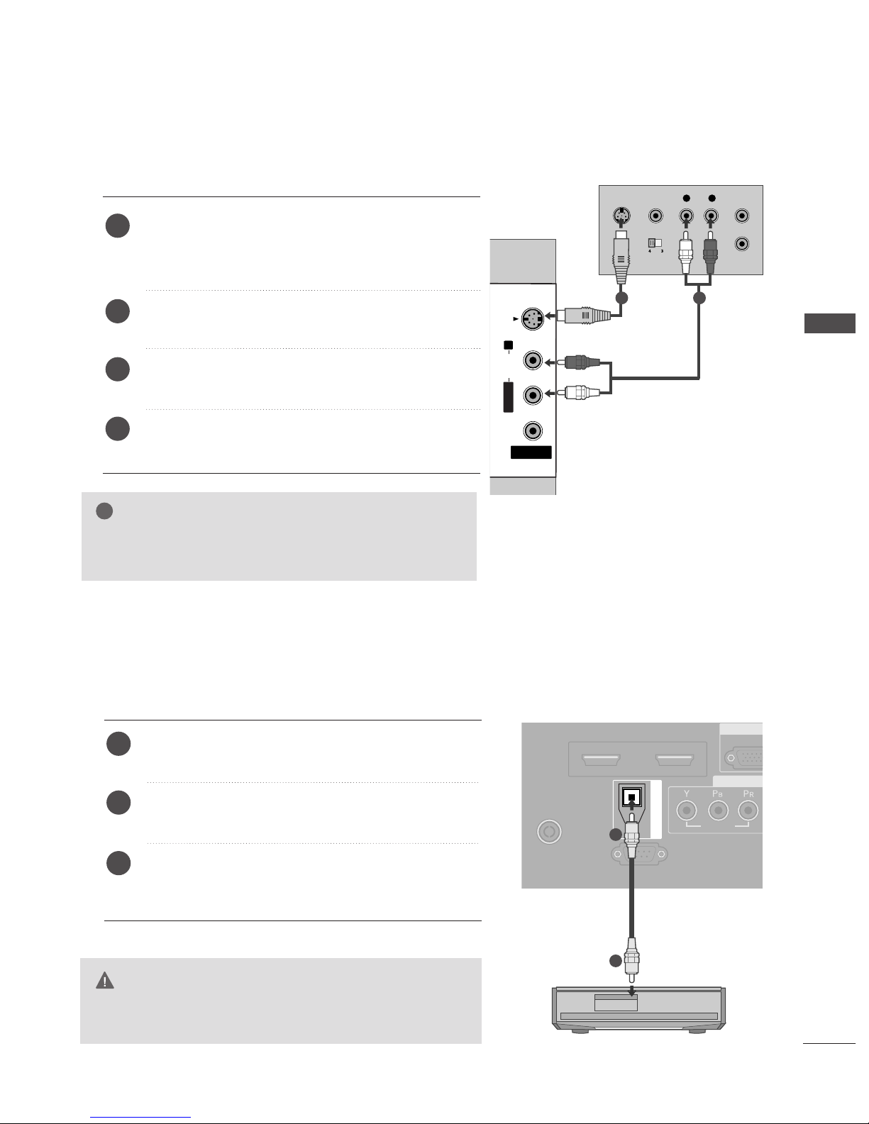
R
S-VIDEO
VIDEO
OUTPUT
SWITCH
ANT IN
ANT OUT
AV IN 3
L/MONOMONO
R
AUDIOAUDIO
VIDEOVIDEO
S-VIDEO
When connecting with an S-Video cable
Connect the S-VIDEO output of the VCR to the
SS--
VVIIDDEE OO
input on the set. The picture quality is
improved; compared to normal composite (RCA cable)
input.
Connect the audio outputs of the VCR to the
AAUU DDIIOO
input jacks on the set.
Insert a video tape into the VCR and press PLAY on the
VCR. (Refer to the VCR owner’s manual.)
Select
AV 3 input source with using the
IINNPPUUTT
button on
the remote control.
2
3
4
1
1 2
DIGITAL AUDIO OUT SETUP
Send the TV’s audio to external audio equipment via the Digital Audio Output (Optical)port.
G
Do not look into the optical output port. Looking at the
laser beam may damage your vision.
CAUTION
RGB
(PC
R
COMP
AUDIO
VIDEO
AV 1 AV 2
ANTENNA
IN
HDMI/DVI IN 1 HDMI IN 2
EJECT PCMCIA
RS-232C IN
(CONTROL & SERVICE)
OPTICAL
DIGITAL AUDIO OUT
Connect one end of an optical cable to the TV Digital
Audio (Optical)Output port.
Connect the other end of the optical cable to the digital audio (optical)input on the audio equipment.
Set the “TV Speaker option - Off” in the AUDIO menu.
(
G
pp..7722
). See the external audio equipment instruction
manual for operation.
2
3
1
1
2
22
EXTERNAL EQUIPMENT SETUP
EXTERNAL EQUIPMENT SETUP
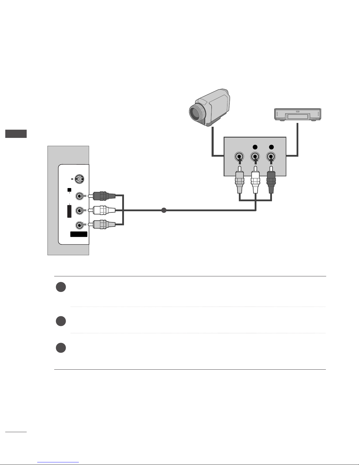
OTHER A/V SOURCE SETUP
Connect the
AAUU DDIIOO/VVII DDEE OO
jacks between TV and external equipment. Match the jack colors
.
(
Video = yellow, Audio Left = white, and Audio Right = red
)
Select AV 3 input source with using the
IINN PPUUTT
button on the remote control.
Operate the corresponding external equipment.
Refer to external equipment operating guide.
AV IN 3
L/MONO
R
AUDIOAUDIO
VIDEOVIDEO
S-VIDEO
L R
VIDEO
Camcorder
Video Game Set
1
1
2
3

23
PC SETUP
This TV provides Plug and Play capability, meaning that the PC adjusts automatically to the TV's settings.
When connecting with a D-sub 15 pin cable
AUDIO IN
(RGB/DVI)
RGB
(PC)
RGB IN
COMPONENT IN
AUDIO
VIDEO
AV 1 AV 2
INRS-232C IN
DIGITAL AUDIO OUT
RGB OUTPUT
AUDIO
Connect the RGB output of the PC to the
RRGGBB ((PPCC
))
jack on the set.
Connect the PC audio output to the
AAUU DDII OO IINN
((RRGGBB //DDVV II))
jack on the set.
Turn on the PC and the set.
Select
RGB input source with using the
IINN PP UUTT
but-
ton on the remote control.
2
3
4
1
1
2
When connecting with a HDMI to DVI cable
GG
If the PC has a DVI output and no HDMI output, a separated audio connection is necessary.
GG
If the PC does not support Auto DVI, you need to set the output resolution appropriately. To get the best
picture quality, adjust the output resolution of PC graphics card's output resolution to 1024x768, 60Hz.
NOTE
!
AUDIO
VIDEO
AV 1 AV 2
ANTENNA
IN
HDMI/DVI IN 1 HDMI IN 2
EJECT PCMCIA
RS-232C IN
AUDIO IN
(RGB/DVI)
RGB
(PC)
RGB IN
COMPONENT IN
AUDIO
VIDEO
AV 1V 1 AV 2
IN IN
HDMI/DVI IN 1 HDMI IN 2
RS-232C IN
(CONTROL & SERVICE)
OPTICAL
DIGITAL AUDIO OUT
DVI-PC OUTPUT
AUDIO
1
2
Connect the DVI output of the PC to the
HHDD MMII// DDVV II
IINN 11
jack on the set.
Connect the PC audio output to the
AAUU DDII OO IINN
((RRGGBB //DDVV II))
jack on the set.
Turn on the PC and the set
Select
HDMI1 input source with using the
IINN PPUUTT
button on the remote control.
2
3
4
1
EXTERNAL EQUIPMENT SETUP

24
EXTERNAL EQUIPMENT SETUP
NOTE
!
G
To enjoy vivid picture and sound, connect a PC to
the set.
G
Avoid keeping a fixed image on the set’s screen for
a long period of time. The fixed image may become
permanently imprinted on the screen; use a screen
saver when possible.
G
Connect PC to the RGB (PC) or HDMI IN (or
HDMI/DVI IN) port of the set; change the resolution output of PC accordingly.
G
There might be noise according to some resolution,
vertical pattern, contrast or brightness in PC mode.
Change the PC mode into another resolution or
change the refresh rate into another rate or adjust
the brightness and contrast on the menu until the
picture is clean. If the refresh rate of the PC graphic card can not be changed, change the PC graphic card or consult it to the manufacturer of the PC
graphic card.
G
The synchronization input waveform for Horizontal
and Vertical frequencies are separate.
G
In Plasma TV models, we recommend using
1024x768, 60Hz for the PC mode, they provide
the best picture quality.
G
Connect the signal cable from the monitor output
port of the PC to the RGB (PC/DTV) port of the
set or the signal cable from the HDMI output port
of the PC to the HDMI IN (or HDMI/DVI IN) port
on the set.
G
Connect the audio cable from the PC to the Audio
input on the set. (Audio cables are not included
with the set).
G
If using a sound card, adjust PC sound as required.
G
This set uses a VESA Plug and Play Solution. The
set provides EDID data to the PC system with a
DDC protocol. The PC adjusts automatically when
using this set.
G
DDC protocol is preset for RGB (Analog RGB),
HDMI (Digital RGB) mode.
G
If required, adjust the settings for Plug and Play
functionally.
G
If graphic card on the PC does not output analog
and digital RGB simultaneously, connect only one
of either RGB or HDMI IN (or HDMI/DVI IN) to
display the PC on the set.
G
If graphic card on the PC does output analog and
digital RGB simultaneously, set the set to either
RGB or HDMI; (the other mode is set to Plug and
Play automatically by the set.)
G
DOS mode may not work depending on video card
if you use a HDMI to DVI cable.
G
When you use too long RGB-PC cable, there might
be a noise on the screen. We recommend using
under 5m of the cable. It provides the best picture
quality.

1366x768
70.08
59.94
75.00
60.31
75.00
74.55
60.00
70.00
75.029
59.87
59.8
59.6
59.988
31.468
31.469
37.684
37.879
46.875
49.725
48.363
56.476
60.123
47.78
47.72
47.56
66.647
25
EXTERNAL EQUIPMENT SETUP
Supported Display Resolution
Resolution
720x400
640x480
Horizontal
Frequency(KHz)
Vertical
Frequency(Hz)
800x600
832x624
1024x768
1280x768
1360x768
RGB[PC] / HDMI[PC] mode
1920x1080
640x480
720x480
720x576
1280x720
1920x1080
59.94
60.00
59.94
60.00
50.00
50.00
59.94
60.00
59.94
60.00
50.00
24.00
50.00
59.94
60.00
31.469
31.469
31.47
31.50
31.25
37.50
44.96
45.00
33.72
33.75
28.125
27.00
56.25
67.433
67.50 0
HDMI[DTV] mode
Resolution
Horizontal
Frequency(KHz)
Vertical
Frequency(Hz)
26
EXTERNAL EQUIPMENT SETUP
EXTERNAL EQUIPMENT SETUP
Screen Setup for PC mode
Automatically adjusts picture position and minimizes image
shaking.After adjustment, if the image is still not correct,
your set is functioning properly but needs further adjustment.
AAuuttoo cc oonnff iigguurree
This function is for the automatic adjustment of the screen
position, clock, and phase. The displayed image will unstable
for a few seconds while the auto configuration is in progress.
Press the
MMEE NN UU
button and then use
D
or
E
button
to select the SCREEN menu.
Press the
G
button and then use
D
or
E
button to
select Auto Config..
Press the
G
button to start Auto Config..
• When Auto Config. has finished, OK will be shown
on screen.
• If the position of the image is still not correct, try
Auto adjustment again.
• If picture needs to be adjusted more after Auto adjust-
ment in RGB (PC), you can adjust the Manual
Config..
Press the EXIT button to return to normal TV viewing.
Auto Configure (RGB [PC] mode only)
Auto Config. G
Manual Config.
XGA Mode
Aspect Ratio
Reset
To Set
OK
EXIT
VOL PR
GUIDE
BACK
MENU
INFO i
FAV
1
3
2
1
2
3
4
Auto Config.
Manual Config.
XGA Mode
Aspect Ratio
Reset
SETUP
O
PICTURE
O
Prev.
MENU
Move
AUDIO
O
TIME
O
OPTION
O
SCREEN
O
27
If the picture isn’t clear after auto adjustment and especially if characters are still trembling, adjust the picture
phase manually.
To correct the screen size, adjust
CC ll oocckk
.
This function works in the following mode : RGB[PC].
CC ll oocckk
This function is to minimize any vertical bars or
stripes visible on the screen background. And the
horizontal screen size will also change.
PPhh aass ee
This function allows you to remove any horizontal
noise and clear or sharpen the image of characters.
Press the MENU button and then use
D
or
E
button
to select the SCREEN menu.
Press the
G
button and then
D
or
E
button to select
Manual Config..
Press the
G
button and then
D
or
E
button to select
Phase, Clock, H-Position or V-Position.
Press the
F
or
G
button to make appropriate adjust-
ments.
Press the EXIT button to return to normal TV viewing.
Adjustment for screen Phase, Clock, Position
Auto Config.
Manual Config.
G
XGA Mode
Aspect Ratio
Reset
Phase
Clock
H-Position
V-Position
0
0
0
0
OK
EXIT
VOL PR
GUIDE
BACK
MENU
INFO i
FAV
1
1
2
3
4
5
Auto Config.
Manual Config.
XGA Mode
Aspect Ratio
Reset
SETUP
O
PICTURE
O
Prev.
MENU
Move
AUDIO
O
TIME
O
OPTION
O
SCREEN
O
EXTERNAL EQUIPMENT SETUP
3 4
2
28
EXTERNAL EQUIPMENT SETUP
To see a normal picture, match the resolution of RGB mode
and selection of XGA mode.
This function works in the following mode: RGB[PC] mode
Press the MENU button and then use
D
or
E
button
to select the SCREEN menu.
Press the
G
button and then use
D
or
E
button to
select XGA Mode.
Press the
G
button and then use
D
or
E
button to
select the desired XGA resolution.
Press the EXIT button to return to normal TV viewing.
Selecting Wide XGA mode
Auto Config.
Manual Config.
XGA Mode
G
Aspect Ratio
Reset
1024 X 768
1280 X 768
1360 X 768
1366 X 768
OK
EXIT
VOL PR
GUIDE
BACK
MENU
INFO i
FAV
1
1
2
3
4
Auto Config.
Manual Config.
XGA Mode
Aspect Ratio
Reset
SETUP
O
PICTURE
O
Prev.
MENU
Move
AUDIO
O
TIME
O
OPTION
O
SCREEN
O
EXTERNAL EQUIPMENT SETUP
3
2
 Loading...