

LG 500M, MB500F-NA Service Manual
W
ebsite:http://biz.LGservice.com
E-mail:http://www.LGEservice.com/techsup.html
COLOR MONITO R
S E RVICE MANUAL
CHASSIS NO. : CA-105
M O D E L : S t u d i o Works 500M
ID LABEL:MB500F-NA
C A U T I O N
BEFORE SERVICING THE UNIT,
READ THE SAFETY PRECAUTIONS IN THIS MANUAL.
CONTENTS
SPECIFICATIONS ................................................... 2
SAFETY PRECAUTIONS ........................................ 3
TIMING CHART ....................................................... 4
OPERATING INSTRUCTIONS ................................ 5
CONTROL LOCATIONS ......................................... 8
WIRING DIAGRAM ................................................. 9
DISASSEMBLY .....................................................10
BLOCK DIAGRAM ................................................. 12
SPECIFICATIONS
1. PICTURE TUBE
Size : 15 inch
DefIection Angle : 90°
Neck Diameter : 29.1mm
Stripe Pitch : 0.28mm
Face Treatment : ARAS(Anti-Reflection and
Anti-Static Coating)
2. SIGNAL
2-1. Horizontal & Vertical Sync
1) Input Voltage Level: Low=0~1.2V, High=2.5~5.5V
2) Sync Polarity : Positive or Negative
2-2. Video Input Signal
1) Voltage Level : 0 ~ 0.7 Vp-p
a) Color 0, 0 : 0 Vp-p
b) Color 7, 0 : 0.467 Vp-p
c) Color 15, 0 : 0.7 Vp-p
2) Input Impedance : 75Ω
3) Video Color : R, G, B Analog
4) Signal Format : Refer to the Timing Chart
2-3. Signal Connector
15-pin Attached Connector
2-4. Scanning Frequency
Horizontal : 30 ~ 61 kHz
Vertical : 50 ~ 160 Hz
3.STEREO AUDIO
3-1. Input Voltage :0.707Vrms
3-2. Input Impedance :20kΩ min
3-3. Amp Output :1W+1W rms
3-4. Speaker Impedance :8Ω
DESCRIPTION OF BLOCK DIAGRAM...................13
ADJUSTMENT ...................................................... 15
TROUBLESHOOTING GUIDE .............................. 17
REPLACEMENT PARTS LIST.................................28
EXPLODED VIEW...................................................35
PIN CONFIGURATION........................................... 37
PACKING AND ACCESSORIES............................ 39
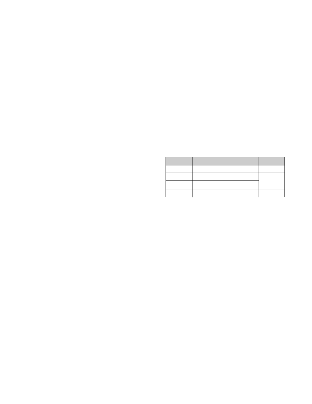
3. POWER SUPPLY
3-1. Power Range
AC 100~240V (Free Voltage), 50/60Hz, 1.5A
3-2. Power Consumption
MODE
NORMAL (ON)
STAND-BY
SUSPEND
OFF
4. DISPLAY AREA
4-1. Active Video Area :
• Max Image Size - 284 x 213mm (11.19" x 8.39")
• Preset Image Size - 270 x 200 mm (10.6" x 7.88")
4-2. Display Color : Full Colors
4-3. Display Resolution : 1024 x 768 / 75Hz
4-4. Video Bandwidth : 78MHz
5. ENVIRONMENT
5-1. Operating Temperature: 10°C ~ 40°C(Ambient)
5-2. Relative Humidity : 10% ~ 90%
5-3. Altitude : 5,000m
6. DIMENSIONS (with FLIP)
Width : 37.0cm (14.6 inch)
Depth : 37.5cm (14.8 inch)
Height : 41.5cm (16.3 inch)
7. WEIGHT (with FLIP )
Net Weight : 12.5kg (27.55lbs.)
H/V SYNC
ON/ON
OFF/ON
ON/OFF
OFF/OFF
POWER CONSUMPTION
less than 74W
less than 15W
less than 15W
less than 5W
(Non-Interlace)
(Non-condensing)
LED COLOR
GREEN
ORANGE
ORANGE
- 2 -

SAFETY PRECAUTIONS
SAFETY-RELATED COMPONENT WARNING!
There are special components used in this color monitor
which are important for safety. These parts are marked
on the schematic diagram and the replacement parts
list. It is essential that these critical parts should be
replaced with the manufacturer's specified parts to
prevent X-radiation, shock, fire, or other hazards. Do not
modify the original design without obtaining written
permission from LG or you will void the original parts and
labor guarantee.
CAUTION:
SAFETY CHECK
Care should be taken while servicing this color monitor
because of the high voltage used in the deflection circuits.
These voltages are exposed in such areas as the
associated flyback and yoke circuits.
FIRE & SHOCK HAZARD
An isolation transformer must be inserted between the
color monitor and AC power line before servicing the
chassis.
• In servicing, attention must be paid to the original lead
dress specially in the high voltage circuit. If a short
circuit is found, replace all parts which have been
overheated as a result of the short circuit.
• All the protective devices must be reinstalled per the
original design.
• Soldering must be inspected for the cold solder joints,
frayed leads, damaged insulation, solder splashes, or
the sharp points. Be sure to remove all foreign
materials.
No modification of any circuit should be
attempted.
Service work should be performed only after
you are thoroughly familiar with all of the
following safety checks and servicing
guidelines.
X-RADIATION
The only potential source of X-radiation is the picture tube.
However, when the high voltage circuitry is operating
properly there is no possibility of an X-radiation problem.
The basic precaution which must be exercised is keep the
high voltage at the factory recommended level; the normal
high voltage is about 29kV. The following steps describe
how to measure the high voltage and how to prevent Xradiation.
Note : It is important to use an accurate high voltage
meter calibrated periodically.
• To measure the high voltage, use a high impedance
high voltage meter, connect (–) to chassis and (+) to
the CDT anode cap.
• Set the brightness control to maximum point at full
white pattern.
• Measure the high voltage. The high voltage meter
should be indicated at the factory recommended level.
• If the meter indication exceeds the maximum level,
immediate service is required to prevent the possibility
of premature component failure.
• To prevent X-radiation possibility, it is essential to use
the specified picture tube.
CAUTION:
Please use only a plastic screwdriver to protect yourself
from shock hazard during service operation.
IMPLOSION PROTECTION
All used display tubes are equipped with an integral
implosion protection system, but care should be taken to
avoid damage and scratching during installation. Use only
same type display tubes.
- 3 -
MODE
MARK
MODE 1
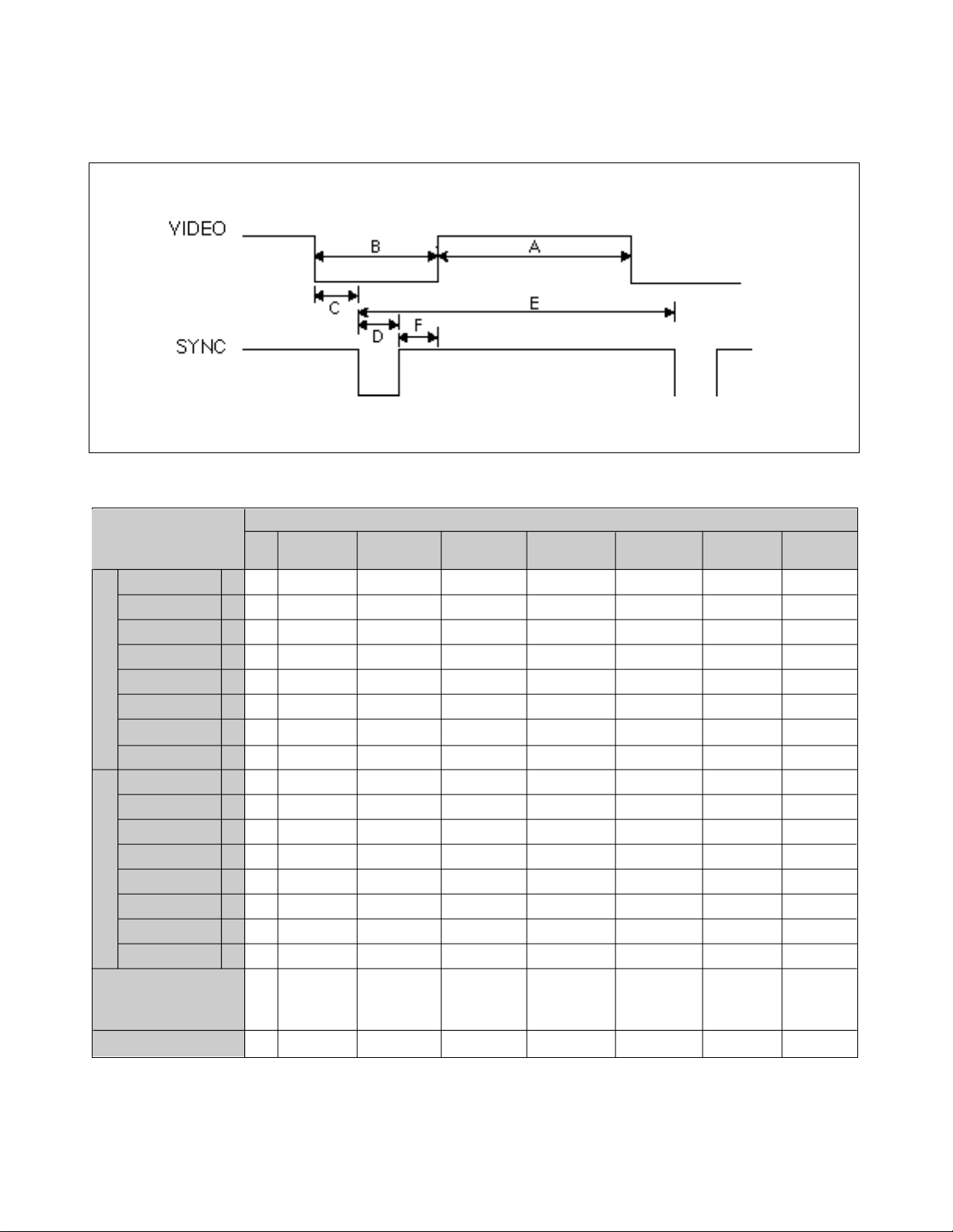
TIMING CHART
FACTORY PRESET MODE
MODE 2
MODE 3
MODE 4
MODE 5
MODE 6
MODE 7
Sync Polarity
H
O
Frequency
R
Total Period
I
Video Active Time
Z
O
Blanking Time
N
Front Porch
T
Sync Duration
A
L
Back Porch
Sync Polarity
V
Frequency
E
Total Period
R
T
Video Active Time
I
Blanking Time
C
Front Porch
A
L
Sync Duration
Back Porch
Resolution
Recall
kHz
µs
µs
µs
µs
µs
µs
Hz
ms
ms
ms
ms
ms
ms
-
31.69
E
31.778
A
25.422
B
6.356
C
1.907
D
3.813
F
0.636
-
59.940
E
16.683
A
15.253
B
1.430
C
1.048
D
0.064
F
0.318
640
x
480
60Hz
Yes
-
31.470
31.780
25.420
6.360
1.910
3.810
0.640
+
70.080
14.270
12.710
1.577
1.080
0.064
0.413
720
x
400
70Hz
Yes
-
37.500
26.670
20.320
6.350
3.810
2.030
0.510
-
74.990
13.335
12.802
0.533
0.427
0.080
0.026
640
x
480
75Hz
Yes
-
43.269
23.112
17.778
5.334
2.222
1.556
1.556
-
85.008
11.764
11.093
0.670
0.578
0.069
0.023
640
x
480
85Hz
Yes
+
46.880
21.330
16.160
5.170
3.230
1.620
0.320
+
75.010
13.331
12.796
0.533
0.448
0.064
0.021
800
x
600
75Hz
Yes
+
53.674
18.631
14.222
4.409
2.702
1.138
0.569
+
85.061
11.756
11.179
0.578
0.503
0.056
0.019
800
x
600
85Hz
Yes
+
60.020
16.660
13.000
3.666
2.240
1.220
0.200
+
75.030
13.328
12.795
0.533
0.466
0.050
0.017
1024
x
768
75Hz
Yes
- 4 -
OPERATING INSTRUCTIONS
To adjust speaker volume in one step.Press to decrease
the volume and to increse the volume.To exit the volume
menu,just press the MENU button.
8. Built-in Mic
Built in microphone.
9. Sound Mute
Use the button to select sound on or off.
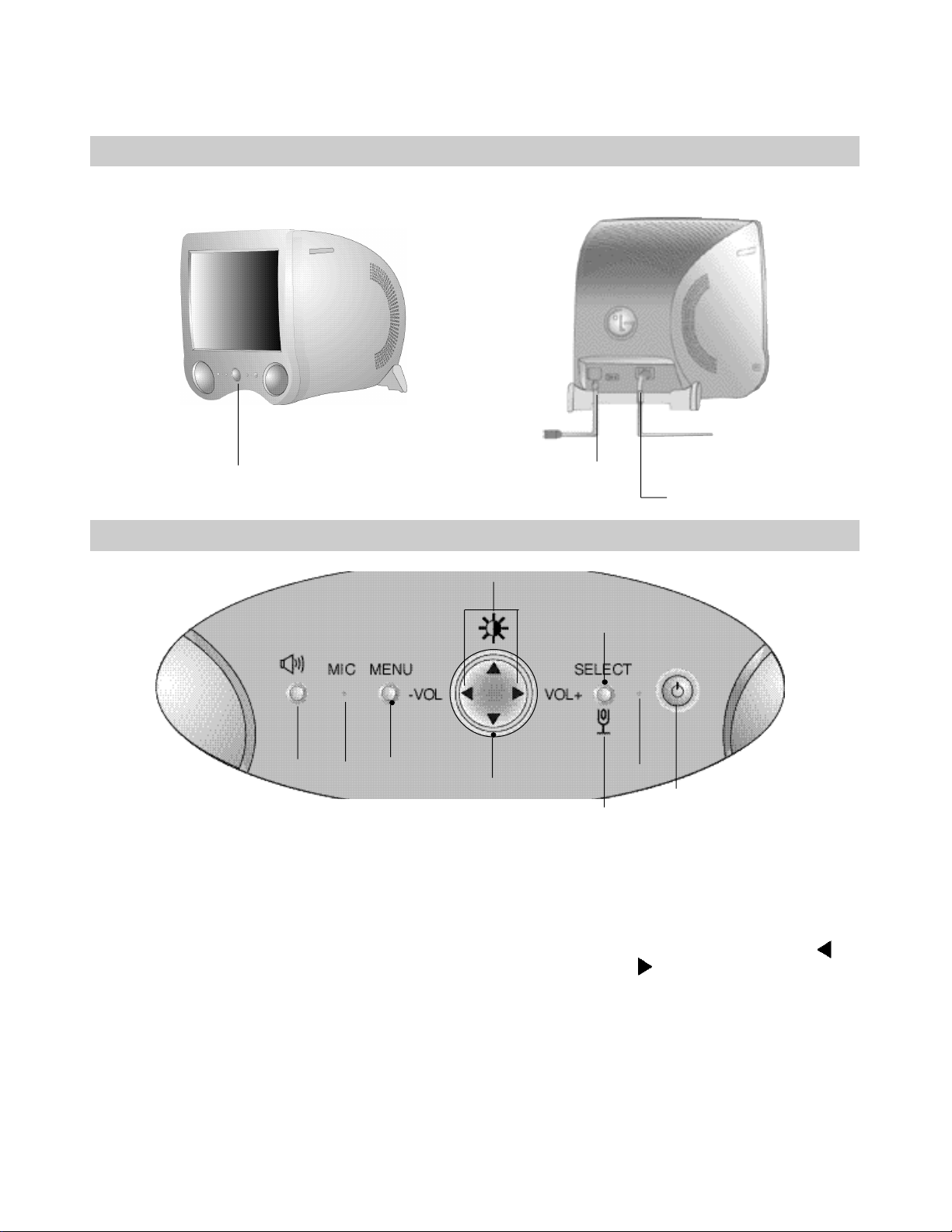
REAR VIEW FRONT VIEW
See Front Control Panel
Front Control Panel
9
8
1. Power ON/OFF Button
This button is used to turn the monitor ON and OFF.
2. Power Indicator
This indicator lights up green when the monitor operates
normally; in DPMS (Energy Saving) mode, stand-by, suspend,
or power off mode -its color changes to orange, and if abnormal
or damaging circuit turns out orange blink.
6
AC Power Socket
7
5
level of the selected menu.
6. MENU Button
This button to enter or exit the on screen display.
7. Volume Button
Signal Cable
3
2
1
4
3. SELECT Button
This button to enter a selection in the on screen display.
4. Mic ON/OFF Button
Use this button to select the MIc on or off.
5. OSD Select/Adjustment
Use for selecting (highlighting) an OSD icon and adjusting
- 5 -
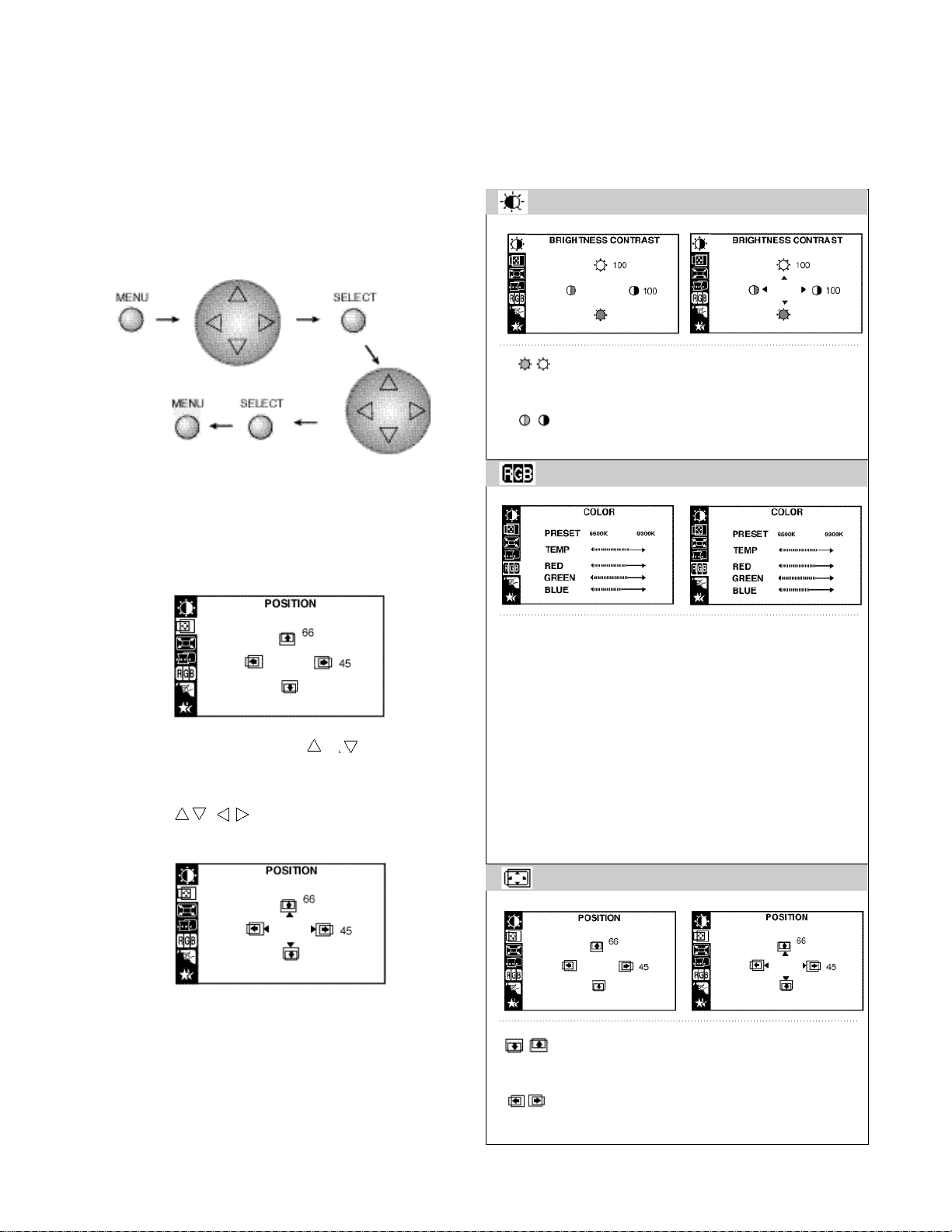
On-Screen-Display (OSD) Control
To adjust an image size, position, and operating
parameters are quick and easy with the On-ScreenDisplay control system, using the OSD button and the
Adjustment control button. A quick example is given below
to familiarize you with use of the controls.
Listed below are icons, icon names, and icon descriptions
of the OSD menu.
BRIGHTNESS CONTRAST
Birghtness
To adjust the screen brightness level.
Contrast
To adjust the image contrast level.
Example;
Note: (Monitor and PC’s power switch should be ON,
with an image or prompt on the screen).
1. Press the MENU Button, then the Main menu of the
OSD appears. Display will look like as below:
2. To access a control, use the or Buttons.
When the icon you want becomes highlighted, Press
the OSD SELECT Button.
3 . Use the / Buttons to adjust the item to the
desired level.
COLOR
6500K 9300K
To appear the display’s color temperature.
• 6500K : Slightly reddish white
• 9300K : Slightly Bluish white
TEMP
User easily color set without adjustment Red,
Green, Blue (R/ G/ B).
RED To set your own color levels.
GREEN To set your own color levels.
BLUE To set your own color levels.
POSITION
4 . Accept the changes by pressing the SELECT button.
5 . Exit the OSD by pressing the MENU Button.
Vertical Position
To move the image up or down.
Horizontal Position
To move the image left or right.
- 6 -
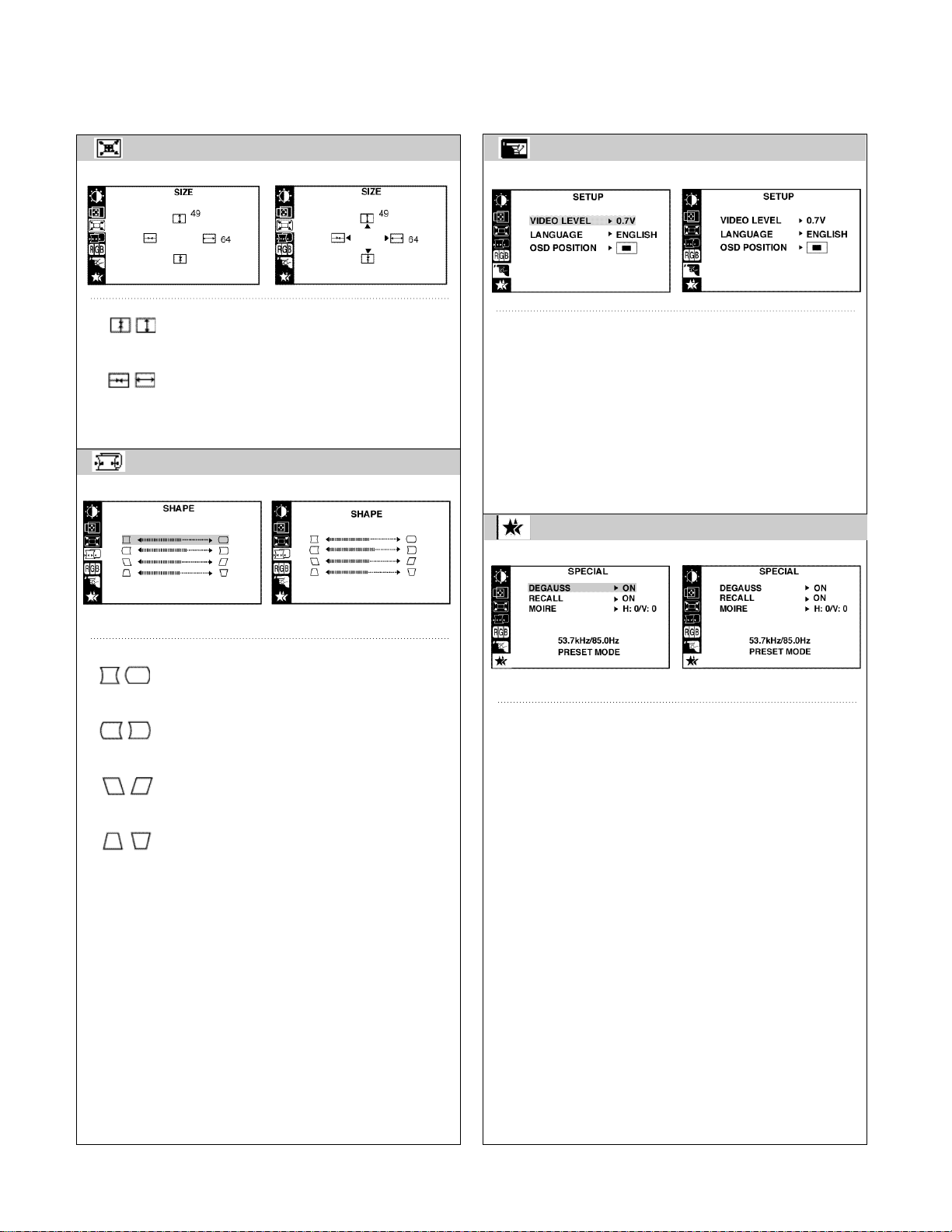
SIZE
SETUP
Vertical Size
To adjust the image height.
Horizontal Size
To adjust the image width.
SHAPE
Side Pincushion
To correct bowing in or out of the image.
Side Pincushion Balance
To correct the balance of both sides bowling.
Parallelogram
To correct the geometric distortion.
Trapezoid
To correct the geometric distortion.
Video Level
To select voltage level of the video card output - It is
input level of the monitor. Most video cards are 0.7V.
Language
To choose the language in which the control names are
displayed. OSD Menus are available in 9 languages.
OSD Position
This item lets you adjust the OSD position.
SPECIAL
Degaussing
Used to demagnetize the picture to give a more
accurate image and color.
Recall
To recall factory preset mode.
Moire
This item allows you to reduce the moire (Moire is
caused by interference Horizontal Scan Line with the
periodical dot screen), It is normally OFF (H:0/V:0)
The moire adjustments may affect the focus of the
screen. The screen image may moire reduction
function is on.
- 7 -
CONTROL LOCATIONS
No.
1
2
3
4
Ref. No.
SW207
SW204
SW205
SW206
Control Function
SOUND BUTTON
MENU BUTTON
OSD SELECT/ADJUSTMENT UP
OSD SELECT/ADJUSTMENT LEFT
- 8 -
No.
5
6
7
8
Ref. No.
SW203
SW202
SW201
SW208
Control Function
OSD SELECT/ADJUSTMENT DOWN
OSD SELECT/SDJUSTMENT
RIGHTSELECT BUTTON
POWER BUTTON
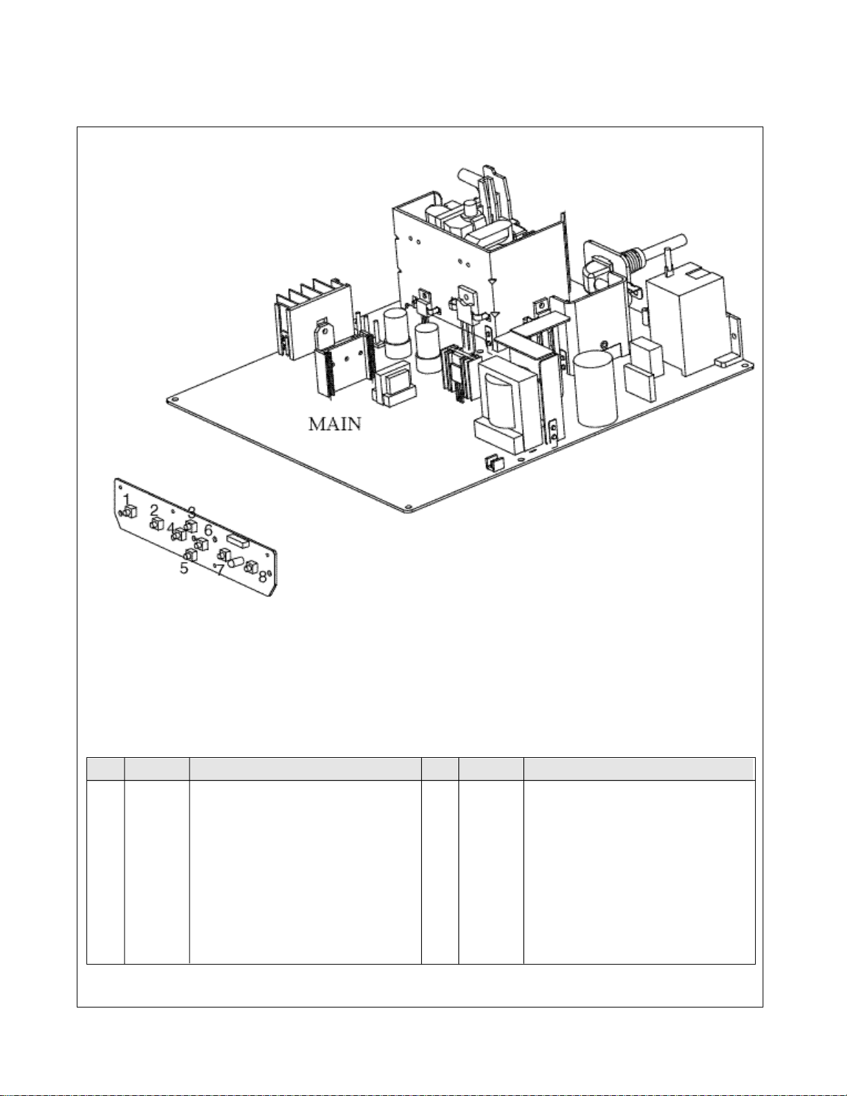
WIRING DIAGRAM
- 9 -
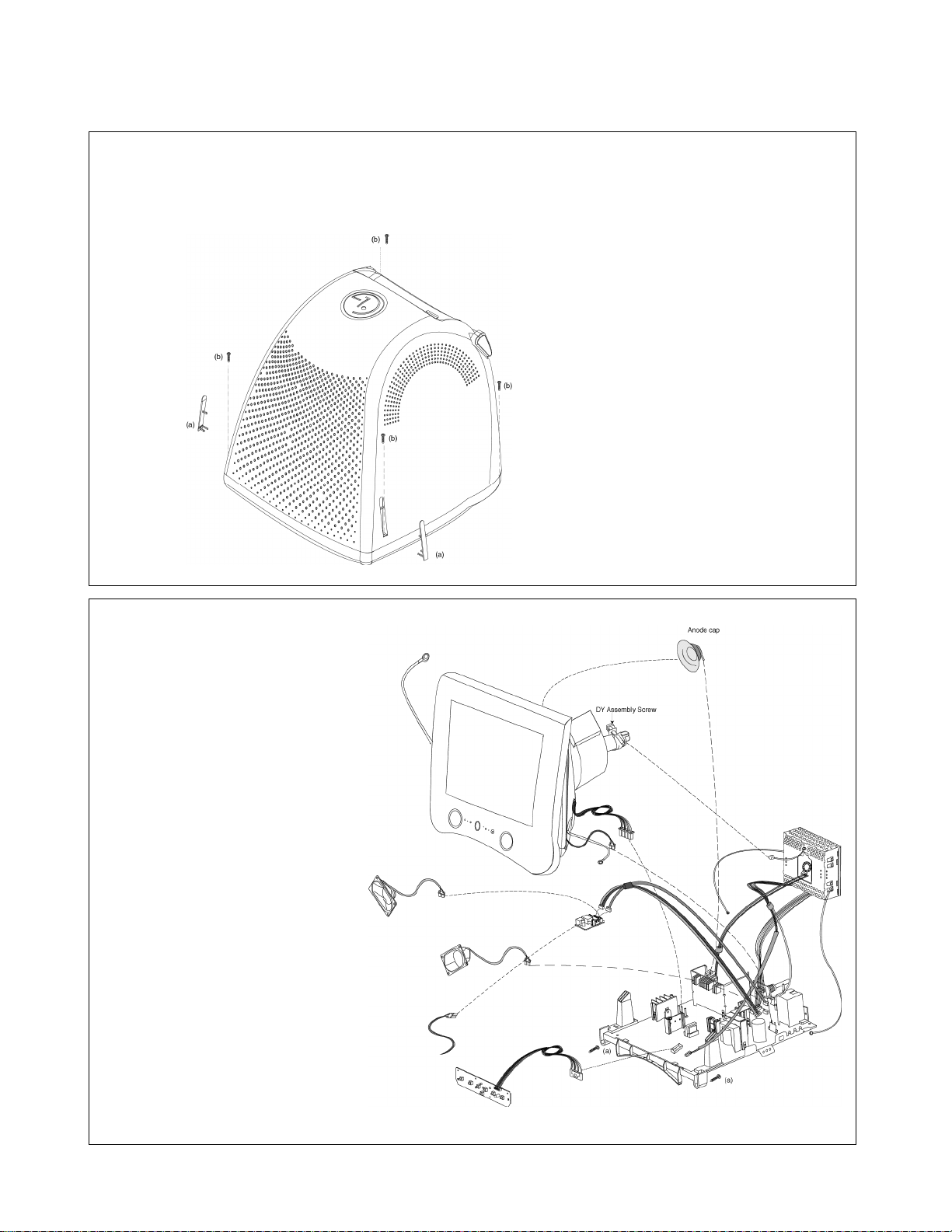
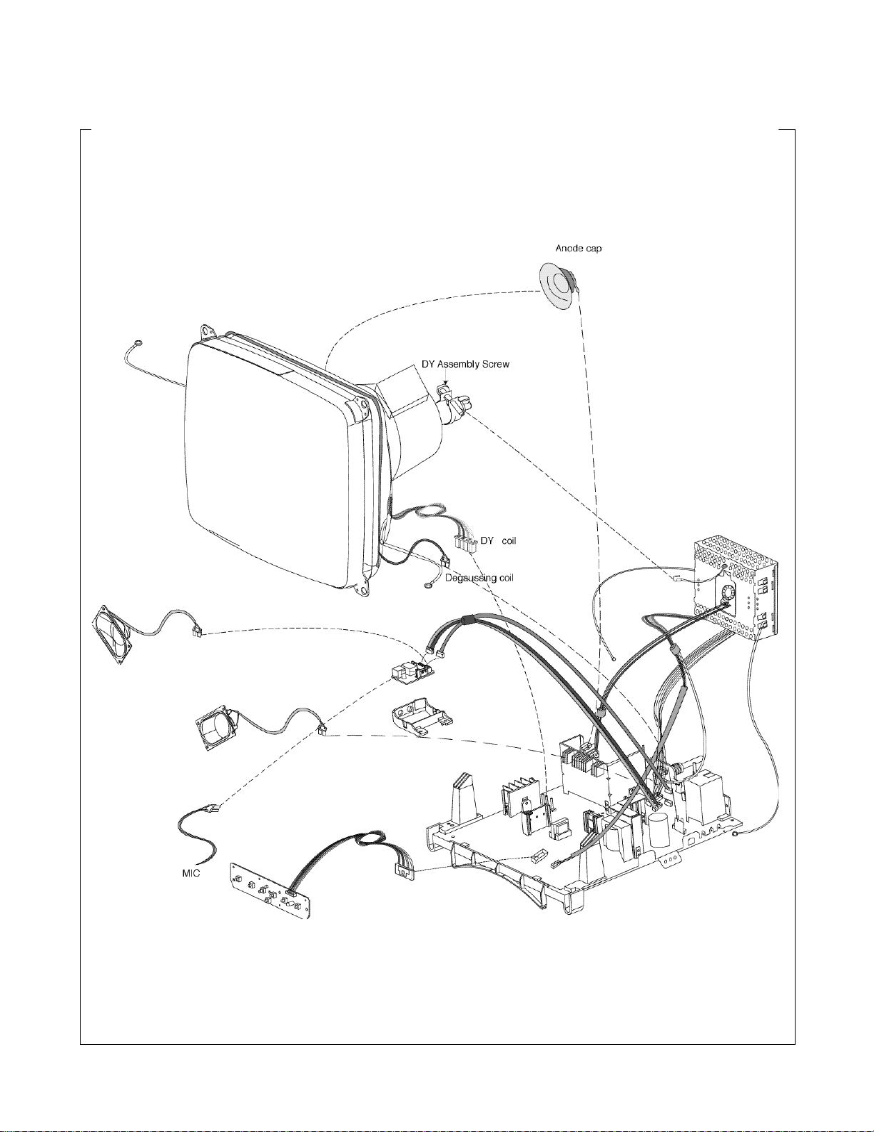
DISASSEMBLY
1. BACK COVER REMOVAL
1) Remove two screw cover (a).
2) Remove four screws(b).
3) Slide the Back Cover away from the Front Cabinet of the monitor.
2. TOTAL CHASSIS ASSEMBLY
REMOVAL
1) Remove two screws (a).
2) Disconnect P701(DY pin),
P902(Degaussing coil),
P405,P3 from the Main PCB.
3) Disconnect the CDT earth
from the Video PCB.
4) Carefully separate the Video
Board Assembly from
the CDT neck.
5) Discharge the remaining
static electricity by shorting
between the Anode Cap
and the CDT ground.
6) Disconnect the Anode Cap
from the CDT.
7) Disconnect P42,P44 from
Audio Board.
8) Remove the Total Chassis
Assembly from the Main
Frame.
- 10 -
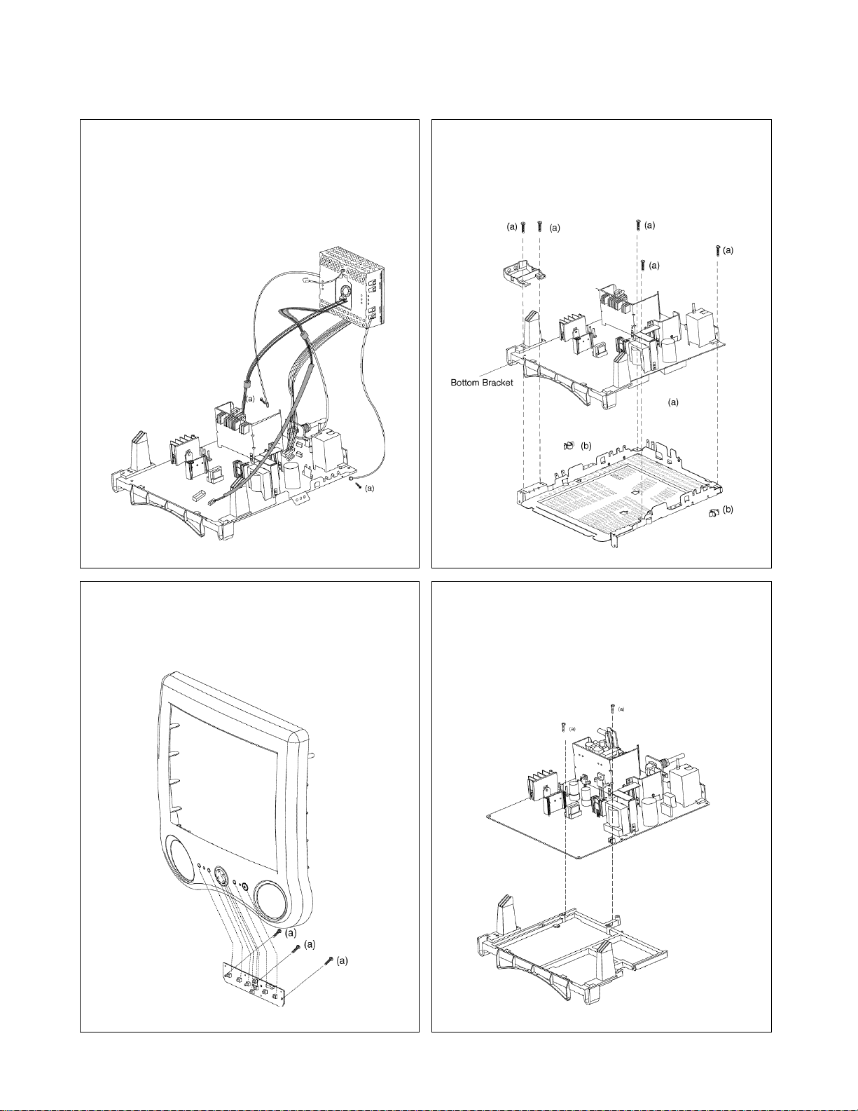
3. VIDEO PCB ASSEMBLY REMOVAL
1) Remove two screws (a).
2) Disconnect P402,P702 .
3) Remove the Video PCB Assembly.
5. BOTTOM SHIELD REMOVAL
1) Remove five screws (a).
2) Remove two latches(b).
3) Remove the Bottom Bracket.
4. CONTROL PCB ASSEMBLY REMOVAL
1) Remove three screws (a).
2) Remove the Control PCB Assembly
from the Front Cabinet.
6. MAIN BRACKET REMOVAL
1) Remove two screws (a).
2) Remove the main bracket.
- 11 -
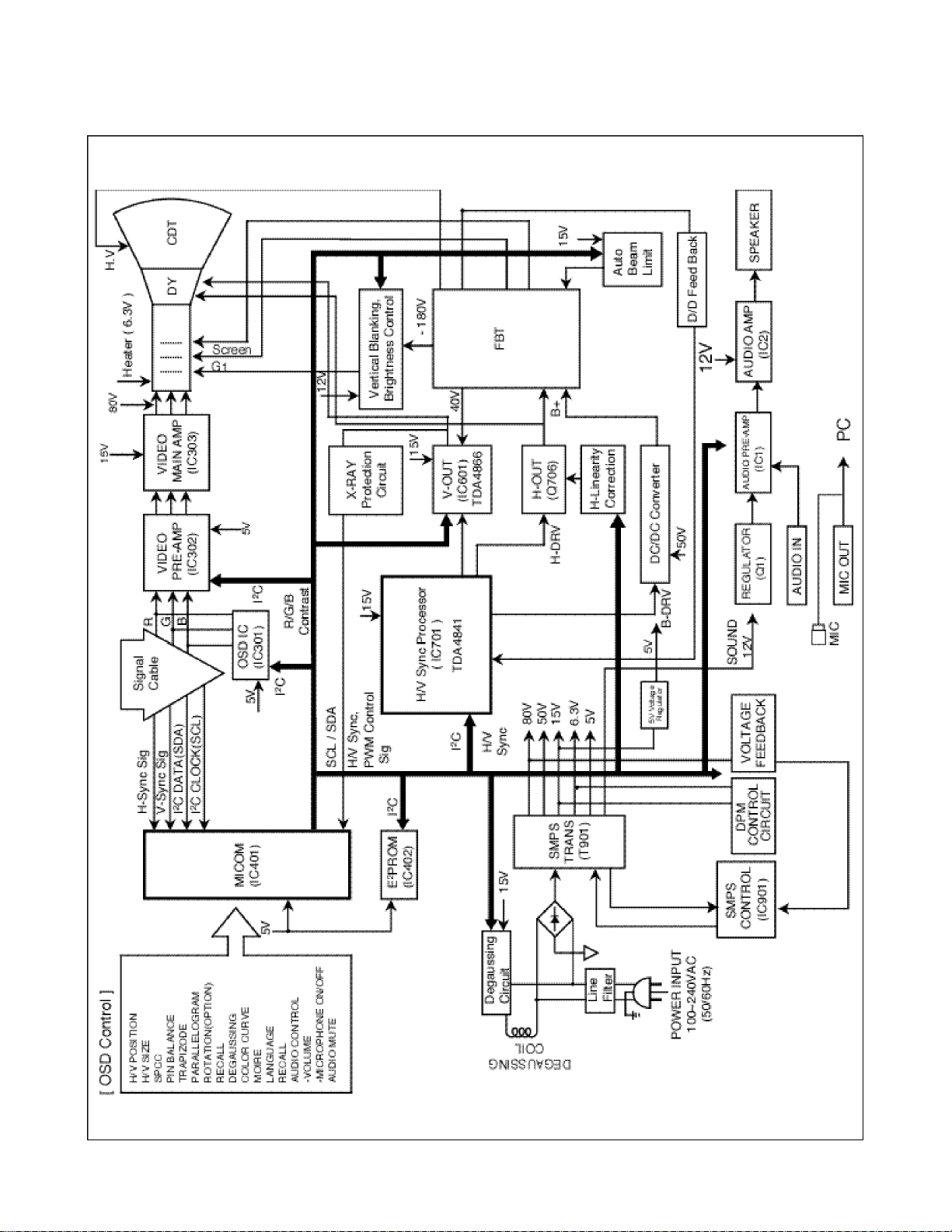
BLOCK DIAGRAM
- 12 -

DESCRIPTION OF BLOCK DIAGRAM
1. Line Filter & Associate Circuit
This is used for suppressing noise of power input line
flowing into the monitor and/or some noise generate in
this monitor flowing out through the power input line.
That is to say,this circuit prevents interference between
the monitor and other electric appliance.
2. Degaussing Circuit & Coil
The degaussing circuit consists of the degaussing coil,
the PTC (Positive Temperature Coefficent) thermistor
(TH901),and the relay(RL901).This circuit eliminates
abnormal color of the screen automatically by
degaussing the shadow mask in the CRTduring turning
on the power switch.When you need to degauss in
using the monitor,select DEGAUSS on the MENU
menu.
3. SMPS(Switching Mode Power Supply)
This circuit is working of 90~264V AC(50/60Hz).
The operation procedure is as follows:
1)The AC line voltage is rectified by the bridge diodes
D900 and the capacitor(C908).
2)The reectified voltage(DC) is supplied to the primary
coil of the transformer(T901)
3)Thecontrol IC(IC901) generates switching pulse to turn
on and off the primary coil of the transformer (T901)
repeatedly.
4) Depending on turn ratio of the transformer,the
secondary voltage appear at the secondary coils of the
transformer (T901).
5) These secondary voltages are rectified by each
diode(D941,D942,D951,D961,D962,D971) and operate
other circuit.(horizontal and vertical deflection,video
amplifier,...etc.)
4. X-ray Protection
If the high voltage of the FBT reaches up to
29kV(abnormal state),Q807 operates and IC401(MICOM)
pin 19 come to low level.Then MICOM control
IC701(Deflection controller) to stop Horizontal drive pulse
and stop Horizontal Deflection.
5. MICOM Circuit
The operating procedure of MICOM(Microprocessor)
and its associated circuit is as follows:
1)H and V sync signal is supplied from the signal cable.
2)The Micom(IC401) distinguishes polarity and frequency
of H and V sync.
3)The Micom sets operating mode and offer the controller
data.(H-size,H-position,V-size,...etc.)
4)The controller data of each mode is stored in itself.
5)User can adjust screen condition by each OSD
function.The data of the adjusted condition is stored
in EEPROM(IC402)
6. Horizontal and Vertical Oscillation
This circuit generates the horizontal pulse and the vertical
pulse by taking the H and V sync signal.
7. D/D Convert Circuit.
This circuit supplies DC voltage to the horizontal
defelection output circuit by increasing DC 50V which is
the secondary voltage of the SMPS in accordance with
the input horizontal sync signal.
8. Horizontal Deflection Output Circuit
This circuit makes the horizontal deflection by supplying
the saw-tooth current to the horizontal deflection yoke.
9. High Voltage Output & FBT (Flyback Transformer)
The high voltage output circuit is used for generating
pulse to the primary coil of the FBT(Flyback Transformer
(T701)).A boosted voltage (about 24.5kV) appears at the
secondary of the FBT and it is supplied to the anode,
focus,and screen voltage of the CRT.
1 0 .Horizontal linearity Circuit.
This circuit corrects the horizontal linearity for each
horizontal sync frequency.
11. Vertical Output Circuit
This circuit input the vertical ramp wave from the IC701
(TDA4841) to the IC601(TDA4866) and amplifies,supplies
the saw-tooth current to the vertical deflection yoke(V-DY)
12. H & V Blanking and Brightness Control
Blanking circuit eliminates retrace line by supplying
negative pulse to the G1of the CRT.And Brightness
circuit is used for control of the screen brightness by
changing DC level of the G1.
- 13 -
 Loading...