

Page 1

LG
IN
START SERVICE MENU SCREENS
In Start Service Menu: Power Off Status
2016 UHD Training Materials
-
49UH6100 webOS
3.0
TV
Page 2

Page 3

Page 4

Page 5

Page 6

Page 7
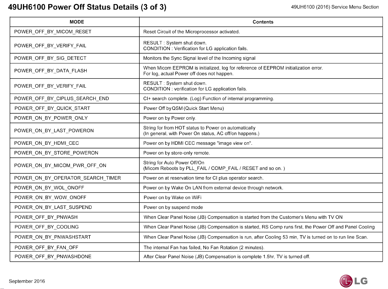
Page 8
LG
2016
UHD Training Materials
49UH6100
WebOS
3.0
UHD TV
POWER SUPPLY TESTING
(Using a Simple 3V Jig)
Page 9
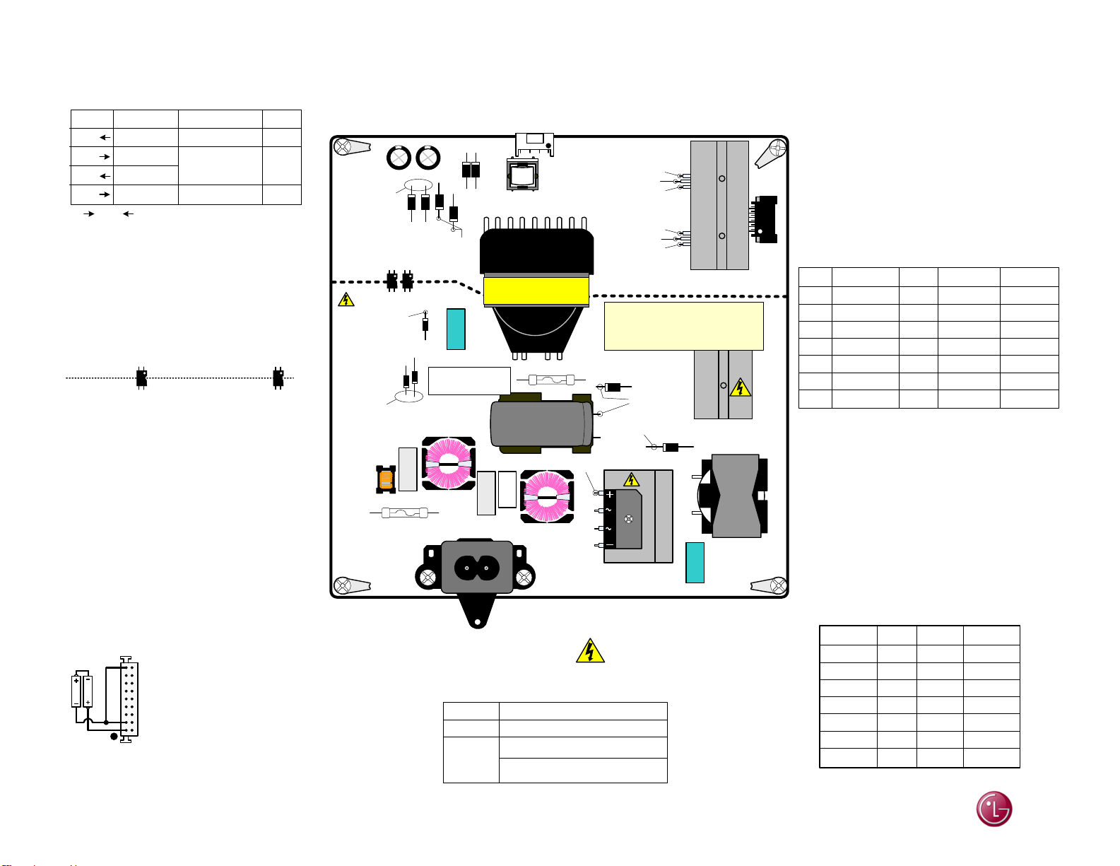
49UH6100 SMPS (Power Supply) Drawing
49UH6100 (2016) Power Supply Section
P801 "SMPS Board" To "LED Backlights"
PIN LABEL RUN Diode
1
3
5
7
LED-
LED+
LED-
LED+
78.4V~55.78V
Pins 3-5 shorted
together on SMPS
123.7V~109.4V
169.0V~163.6V
In Out Dim to Bright
No Stand-By Voltages Backlights *0% to 100%
Pins 2, 4, 6 are n/c.
Pins 3 and 5 are jumped together
Direct Lit Backlights (LED Array Strips)
36 Total LEDs. 4 Strips with 9 LEDs per/strip.
IC102
Chassis
Gnd
SMPS TEST: Forcing SMPS On.
This test requires simple 3V jig. See below..
Remove AC Power.
Disconnect P2502 on Main Board.
Test 1: Using a 3V jig, Jump 3V to pin 1 (PWR_ON).
Apply AC Power. (No Backlights in Test 1)
(Pins 4-8) rises to 13.14V. Backlight Power 160.8V.
Remove AC Power. P_DIM will be 10.12V
Test 2: Using a 3V jig, Jump 3V to pin 11 (DRV_ON).
Apply AC Power. All Voltages should be produced.
(13.14V to Main and 149.7V to the Backlights).
This will also force the Backlights to come on.
P_DIM will be 10.12V
Test 2
2 AA (3V)
Test 1
1) 11.54V
2) 10.52V
Gnd
Hot
3) Hot Gnd
4) 1.50V
P201
11 12
3
12
Test Set Up
Chassis
Gnd
P201 still inserted. P2502 removed.
Use P2502 side to insert resistors.
Note: 7.90V (Pins 4-8)
Must be present when AC is applied before
beginning test indicating Standby is OK.
3V JIG: Made from 2 (AA) batteries.
Jump + to – on one side.
On the other side, solder two red wires
(needle tipped) to the + and one black wire
(needle tipped) to the – side.
IC103
1) 1.10V
2) 0V
Gnd
Hot
3) 16.87V
4) 20.96V
Note:
September 2016
OL
OL
OL
Backlight
Power
IC102
Primary
23.40V
D107
D109
200V
LF103
5A / 250V
To Panel Backlights (Dim to Bright)
Backlight Power 169.0V~163.6V pin 7
Pin 1 goes to Backlight Driver Q801 (Back of SMPS)
D802
D204
D206
D205
IC103
D803
D203
80V
L801
T101
P801
Gnd
13.12V
Gnd
Gnd
13.12V
Gnd
Secondary
SMPS
P/N: EAY64388811
D101
Run: 400V
STBY: 186.7V
CX101
LF101
F100
SK100 AC
MODEL LGP49L1U-15CH1
OUTPUT
3.15A / 250V
F101
460V
68uF
TH101
CX102
LF102
VOLTAGE LABEL
AC100V~240V~50/60Hz. 2.5AINPUT
115V – 500mA
D602
C611
106V
+
-
400V
107.2V
D601
BD101
AC
HGnd
All 6 screws are M3X5L (Silver)
Hot Gnd
(Shock Hazard)
13.2V = 3.7A
Page 01
D201
D202
Can’t Read
L601
P201
Can not use Smart Test Jig on this model for
SMPS test mode.
Can not run normal Panel Test by removing
Vx1 cable on T-CON and supplying 12V to
T-CON fuse. It will not work. Can not use
Smart Test Jig on this model for T-CON test.
P201 "SMPS Board" To P2502 "MAIN Board"
PIN LABEL RUN DiodeSTBY
(3)
(2)
9-10
(1)
backlights at this time. Backlight Power is 160.8V.
(2)
Backlight power goes to 169V.
(3)
according to incoming video IRE level and OSD Backlight
setting Output from the Video Processor. It is then routed
out P2300 to P201 and sent to the LED Driver IC on the
Back of the SMPS.
The Range is: 0.18V~3.24V.
P_DIM1
12 0V
MS (Drv_On)
11
Gnd
4-8
(3)
(1)
13.2V
3
PWR-On Pin 1: Turns on 13.2V to the Main. No
MS (DRV_On) Pin 11: Turns on the Backlights.
P_DIM#1 Pin 12 and P_DIM#2 Pin 2: Will vary
Gnd
N/C
2
PWR_ON
1
SMPS
P201 P2502
Label Label
P_DIM1
MS
Gnd
12.2V
Gnd
N/C
PWR_ON
Pin
12
11
9-10
4-8
3
2
1
*0.18V-3.24V
0V
Gnd Gnd
7.90V
Gnd
n/c
0V
2.03V
13.11V
Gnd
3.29V
*Dim to Bright
MAIN
Pin
2
1
3-4
5-8, 10
9
12
11
n/c
DRV_ON
OL
OL
Gnd
OL
Gnd
n/c
0.87V
LG
Page 10
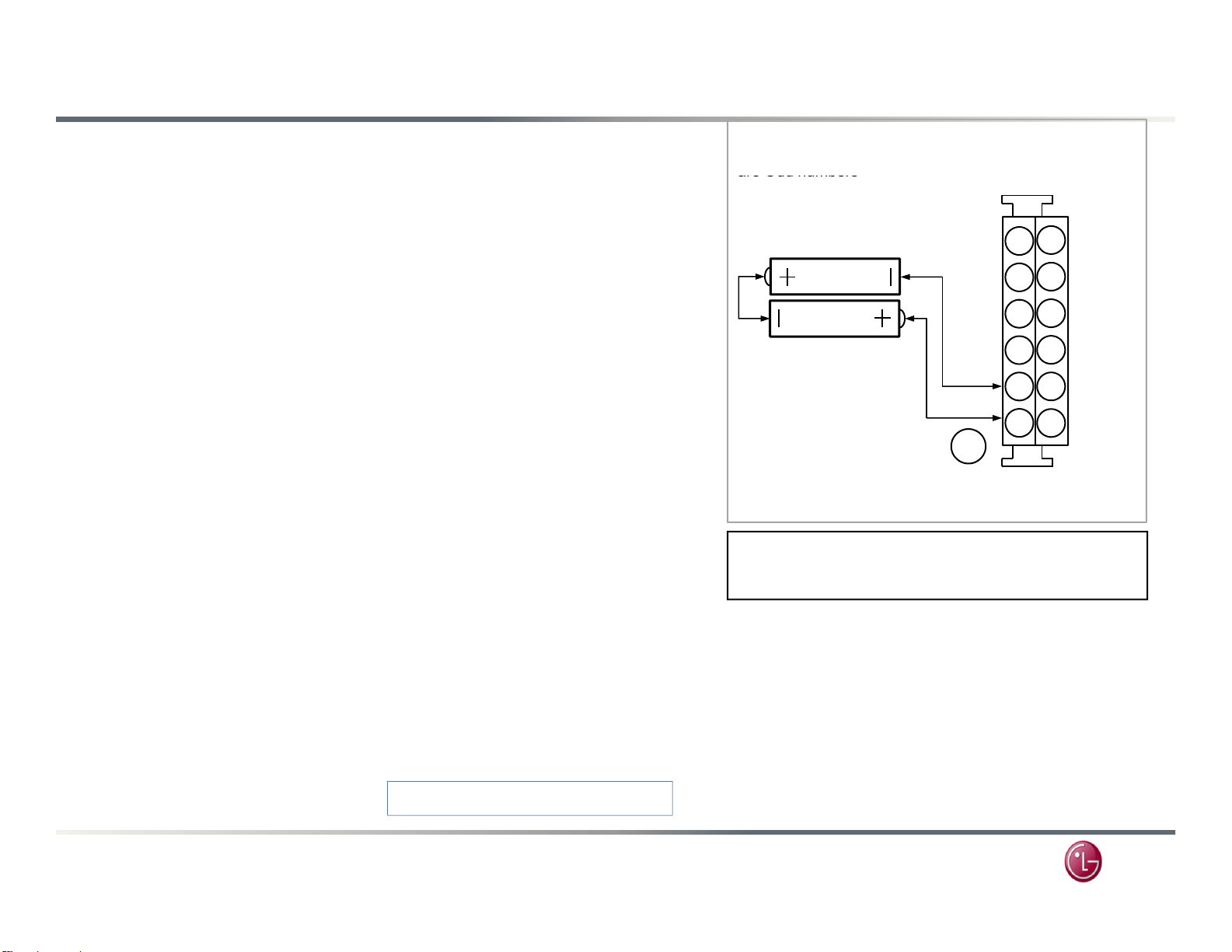
Power Supply Board Low Voltage Test 1
SMPS
thi
are Odd numbers
of P2502
To Main Board Power:
–
Caution:
Pins on Main are not the
49UH6100 (2016) Power Supply Testing
Note: The numbers in Fig 1 refer to the “Main” board connector (from the
SMPS) that has been unplugged. Use this end for easy insertion of needles.
connector pins are the same as the Main on
s chassis.
AC Should not be applied at any time while adding connectors or while
unplugging connectors, damage to the circuit Board may occur.
I) When AC is applied, the SMPS “MUST” be producing STBY 7.9V on pins 4-8,
of P201. [Pins 5-8, and 10 on Main P2502].
If STBY is missing, STBY voltage may be loaded down by the Main Board or the
Joy Stick/IR Board. Remove connector P2502 on Main board from SMPS. If
STBY is still missing, SMPS is defective but make sure AC is arriving at the
connector SK100.
II) With P2502 on the Main Board unplugged, it will make insertion of the Needle
tips easier. Use P2502 (Main Board side) to insert connections during these
tests. Pin numbers will be given from P201 side. Brackets [ ] indicate Main.
TEST 1: TESTING THE POWER SUPPLY TURN-ON CIRCUIT. (See Fig 1)
(1) Using two AA 1.5V batteries hooked in series (3V supply) jump the negative
lead to ground (pin 3) [Main pin 9] and the positive lead to PWR-ON (pin 1)
[Main pin 11] as shown in example (A) in Fig 1 on the right.
Apply AC, this will turn on the SMPS. No Relay click will be heard.
Check that the 13.2V supplies that go to the Main board turn on;
• [P2502 “13.14V” pins 5-8, 10]
• (P201 “13.14V” 4-8)
SMPS TEST 1
Top Row pins
Female side
Fig 1
12
2 (1.5V Batteries)
Size: AA
3V
12.2V
Gnd
PWR_ON
11
9
7
5
3
1
10
8
6
4
2
A
STAND-BY VOLTAGE:
7.90V in STBY, 13.11V in Run
Pin 1 Bottom Front on SMPS
Pin 1 is Top Front on Main
Top row is odd pins, bottom row is even pins.
WARNING:
Do not to let the leads touch positive (+) to
negative (
battery to overheat creating a fire hazard.
) at any time as this will cause
12.2V12.2V
12.2V
12.2V
(2) Remove AC Power (Leave Battery connected in this configuration).
same as pins on SMPS.
See bottom of page 1 .
September 2016
Use SMPS side for pin count.
Page 02
LG
Page 11
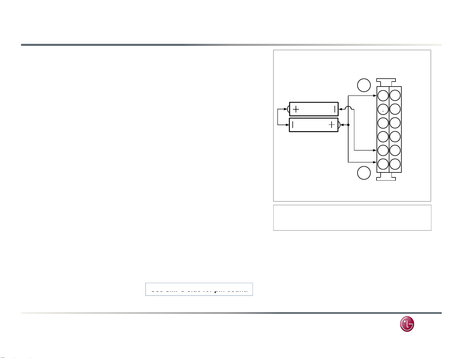
Power Supply Board Backlights Test 2
AC Power is removed at this time
0
9
0
Do not to let the leads touch positive (+) to
Use
SMPS
side for pin count.
49UH6100 (2016) Power Supply Testing
Continue if the 1sttest was OK. Leave original jumper (A) in place.
.
TEST 2: Backlight Section (Using P2502 side)
(3) (B) Jump the 3V to Pin 11 MS (DRV_ON). (See Fig. 2),
Simulating a Power On and Backlight On command.
(4) Apply AC Power.
Backlights Normal: Backlight Power 149.7V
a) If normal, the backlights will be on.
SMPS OK, Backlight Section OK. Backlight power P801 pin 7 (149.7V).
Backlights Abnormal:
a) Recheck all connections.
b) Confirm the PWR_ON and DRV_ON lines are pulling up to at least 3V.
c) Check the connections to the Panel’s Backlights.
If the DRV_On command is pulling up to 3V and the 149.7V is being Generated
at P801, suspect a Panel’s Backlight Section problem.
Note: If P801 is disconnected, the backlight power will come on,
start at 112V climb to 122V and stay there.
SMPS TEST 2
Top Row pins
are Odd numbers
Fig 2
Female side
of P2502
B
2 (1.5V Batteries)
Size: AA
3V
DRV_ON
12.2V
Gnd
PWR_ON
11
7
5
3 4
1
A
Pin 1 Bottom Front on SMPS
Pin 1 is Top Front on Main
Top row is odd pins, bottom row is even pins.
12
1
8
6
2
12.2V12.2V
12.2V
12.2V
Remove AC Power, Remove all Jumpers and
Reconnect P2502 on the Main.
Caution: Pins on Main are not the
same as pins on SMPS.
See bottom of page 1 .
September 2016
WARNING:
negative (–) at any time as this will cause
battery to overheat creating a fire hazard.
Page 03
LG
Page 12
Power Supply Board Voltage Reading During Test Modes
4-8
13.2V
13.14V
13.14V
P201 "SMPS Board" Stand-Alone Test
Pin Label Test 1 Test 2
12
11
9-10 Gnd Gnd Gnd
(3)
P-DIM#1 10.20V 10.12V
(2)
DRV-ON 0.48V 3.10V
LED Power during TEST 1. Pin 7 P801 160.8V
LED Power during TEST 2. Pin 7 P801 149.7V
Test 1 LED Ground Return Line Pin 1 P801 76.6V
Test 2 LED Ground Return Line Pin 1 P801 40.47V
49UH6100 (2016) Power Supply Testing
3GndGnd Gnd
(3)
2
1
P-DIM#2 0V 0V
(1)
PWR-ON 3.11V 3.11V
Test 1 = PWR_ON only
Test 2 = PWR_ON and DRV_ON
Main board is disconnected
BL = Backlights
September 2016
BL Off BL On
Backlight Driver Q801
Backlight Controller IC is IC801
D204 and D206 Backlight Power Source P801 pin 7
D201 and D202 13.2V Source
SMPS Controller IC is IC101
Page 04
LG
Page 13
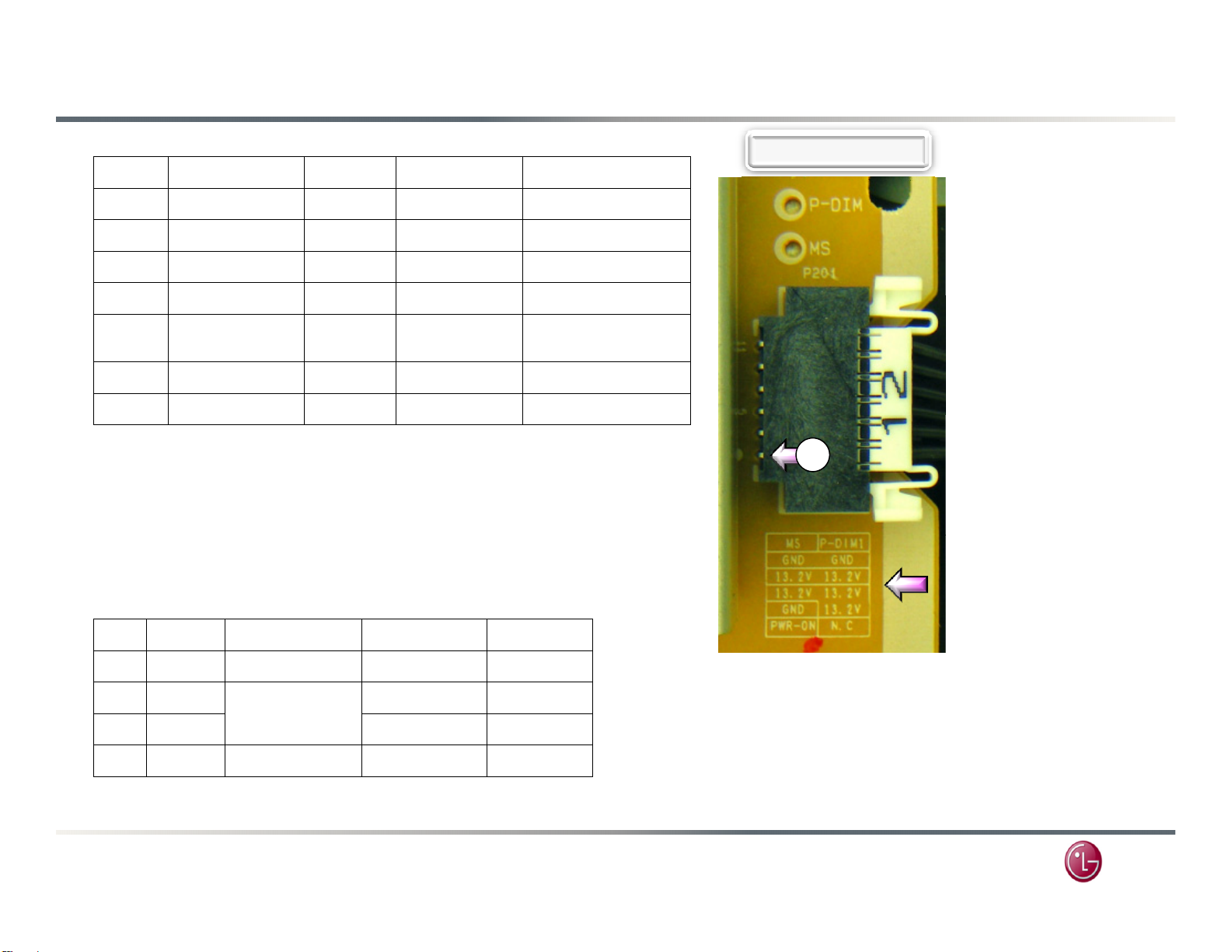
P201 Power Supply Connector Voltage and Diode Check
Pin
Label
STBY
Run Diode Check
4-8
13.2V
7.90V
13.11V
OL
T
Drive
Backlights turn on at this time
49UH6100 (2016) Power Supply Testing
P201 "SMPS Board" to "MAIN Board" P2502
12
11
9-10 Gnd Gnd Gnd Gnd
3GndGnd Gnd Gnd
2N/C n/c n/c n/c
1
(1) PWR_ON: turns on the 12V (7.90V in STBY) and 24V lines.
Backlight power is 160.8V. Backlights are not on.
(2) MS (DRV_ON) Pin 2: Turns on the 169V Backlight Power and Backlight
Diode Mode values taken with all Connectors Removed
P801 "SMPS Board" To "Panel LEDs"
(3)
P-DIM1 0V 0.18V~3.24V OL
(2)
MS (DRV_ON) 0V 2.03V OL
(1)
PWR-ON 0V 3.29V 0.87V
(3)
Dim to Bright
.
.
P201 to Main
op Row of pins are odd
numbers
1
Pin Silk Screen Label
Pin Label Run Diode Check 50% B/L
1
3
5
7
In
Out
September 2016
LED- 78.4V~55.78V OL 66.2V
LED+
LED- OL 116.0V
LED+ 169.0V~163.6V OL 163V
123.7V~109.4V
Jumped Together
*Dim (0%) to Bright (100%)
OL 109V
Page 05
(3) P_DIM1: Controls the backlight brightness. Controlled via the
Customer’s Menu: Home Settings Picture Backlights. Range
0% to 100% directly proportional to DC voltage to Backlight
brightness. (0.18V~3.24V).
P_DIM is actually a Pulse Width Modulated Signal.
LG
Page 14
LG
T
y
Published September 09
2016
2016 Direct View UHD Training
49UH6100 WebOS
3.0
UHD LCD TV
T-CON BOARD INFORMATION
-CON Board Layout and
Voltage Measurements
th
,
Updated October 10th, 2016
Page 15

49UH6100 T-CON Board (Photo)
49UH6100 (2016) T-CON Board Section
October 2016
Page 01
LG
Page 16
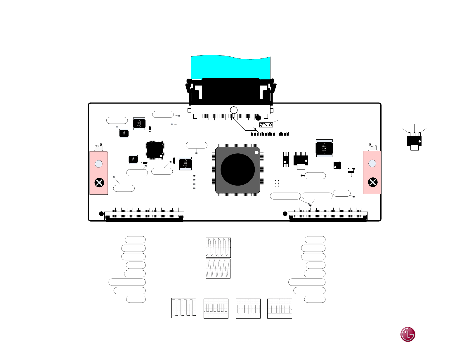
49UH6100 T-CON (TFT Drive) Components Identified
Caution: Make sure the screws are installed when the T-CON is operating, damage may occur without them.
49UH6100 (2016) T-CON Section
PANEL TEST: ROLLING TEST PATTERNS
1) With no Power,
2) Jump 12V from
r 12V from SMPS use D202 (center leg) Top
Fo
ri
ght hand heat sink.
3) J
ump VCC (3.3V) to pin 23 of CN1.
r easier contact to pin 23, use top side of R111.
Fo
remove CN1 (Vx1 Cable)
SMPS to Fuse F1.
(7.70V)
HVDD
FL3
VGH
(28.09V)
VST
(-7.01V)
5 1015202530354045505560
35
51
52
D2
CN2
(3.29V)
VCC
D1
U5
VGL2
(-7.05V)
Warning: Do not use the
Smart Jig on this T-CON.
Damage will occur.
TO MAIN
Warning Do Not Use Jig
LVDS
CN1
VIN: (PANEL_VCC 12V)
Pins 1-8 (11.97V)
From Main
Panel_VCC Supply
CN1
R111
GndGnd
144
176
133
(12.90V)
F1 (VIN)
5A/125V
F1
U1
10Mhz
RS1
(-7.01V ~ 28.09V)
VGH-ODD
U4
(15.84V)
VDD
Q3
Source
VDD
U3
VCC18
VGH-EVEN
(1.81V)
CN3
5 1015202530354045505560
FL2
(3.28V)
U4
(1.81V)
(Gnd)
(1.81V)
23
Vcore
(1.20V)
1834
17
D3
1
69
(-7.05V)
VGL1
45
UC1
GCLK
MCLK
GST
EQ
88
89 132
VGH-ODD and VGH-EVEN
Toggles between
29.09V to -7.05V every second.
October 2016
CN2 Key Voltages CN3 Key Voltages
Vcore
VCC18
HVDD
VDD
VGL1
VGH_EVEN
VGH_ODD
VGH
Pin 33
Pin 34, 35
Pin 36
Pin 37-40
Pin 45
Pin 49
Pin 50
Pin 51
CLK1 – CLK8
32.8V - 33.0V p/p
All have similar
waveforms
GCLK
3.56V p/p
Page 02
RS1
1.63Vdc
3.72V p/p
Top Legs
1.56Vdc
3.58V p/p
Bottom Legs
MCLK
3.60V p/p
EQ: No Waveform
GST
3.24V p/p
Vcore
VCC18
HVDD
VDD
VGL1
VGH_EVEN
VGH_ODD
VGH
Pin 28
Pin 26, 27
Pin 25
Pin 21-24
Pin 16
Pin 12
Pin 11
Pin 10
Pin 1
Pin 2
Pin 3
Pin 4
Pin 5
Pin 6
Pin 7
Pin 8
U1
Gnd
Gnd
Gnd
Gnd
3.27V
3.26V
3.29V
3.30V
LG
Page 17
LG
M
2016 Direct View UHD Training
49UH6100 WebOS
3.0
UHD LCD TV
TELEVISION TURN ON COMMANDS
ain Board Side
Television Turn On Commands
Page 18
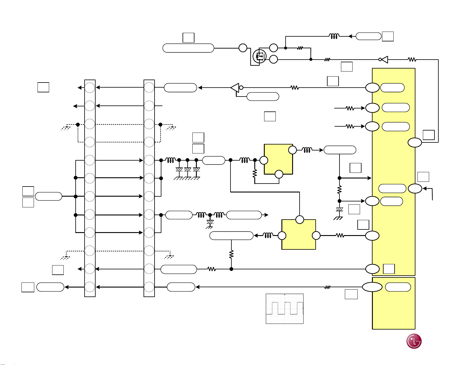
49UH6100 Power Supply Control Circuit Drawing
49UH6100 (2016) Power Supply Section
4
STBY: 7.90V
RUN: 13.11V
1
13.2V
5
P-DIM#1
10
PWR_ON
SMPS
P201
1
2
9
10
5
3.29V
N/C
Gnd
Gnd
13.11V
13.11V
MAIN
P2502
6
4
7
8
3
MS
9
11
12
P-DIM1 (PWM Dimming) can vary according
to incoming video IRE level, OSD Backlight
setting. Range 0.18V to 3.24V.
13.11V
13.11V
13.11V
Gnd
2.03V
0.18V~3.24V
11
12
3
4
7
8
10
5
6
9
1
2
8
Panel_Vcc (12V)
PWR_ON
N/CN/C
1
L2502
C2505
0.1uF
13.17V
A13V
INV_CTL
P_DIM1
5
L2503
C2511
10uF
13.01V
Q2500
3.29V
STBY: 7.90V
RUN: 13.11V
+13V
C2508/12
10uF
L2500
+3.3V_Normal
3.31V
R2503
100Ω
3.49V
50% Backlight
Setting. 120Hz
Q2504
3
3.40V
2.67V
2
1
+13V_AMP
+3.5V_ST
L2313
R2346
10K
To IC5800
Pins 19, 20, 31, 32
R2501
1K
P_DIM
3.44V p/p
DC: 1.71V
13.05V
SD
G
10.50V
R2300 10K
P4100 (pin 15)
3
Power Button
P4000 (pin 19)
8
IC2306
EN
1
12.78V
13.11V
L2300
2
3.31V
+3.3V_Normal
Goes to other circuits
R2519
L2312
6
3.48V
13.11V
5
IC2302
EN
L2504
R2520 150K
4
IR
Key 2
3.49V
+3.5V_ST
R3030
10K
C3004
0.1uF
R2304 10K
5
3.39V
R2509 100
7
Off: Hi
On: Lo
0.01V
R4121
100Ω
R4104
100Ω
3.46V
3.46V
2
3.40V
Off: Lo
On: Hi
3.42V
Ω
10
13.15V
1
+13V
Q2503
0.05V
36
6
32
40
7
33
19
AM24
5
0.56V
RL_ON
3.40V
IR
3.40V
Joy Stick
0V when
Pressed
IC3000
Micro
48
Power Det
Reset
PWR_ON/
OFF2_1
9
P_DIM
IC100
Processor
R2518
10K
PANEL_CTL
8
19
1.37V
6
14
3.48V
IC2304
(pin 2)
Senses
12.2V
September 2016
Page 01
LG
 Loading...