

LG 49LS75A-5B, 42LS73B-5B, 55LS75A-5B Owner’s Manual

OWNER’S MANUAL
MONITOR
SIGNAGE
Please read this manual carefully before operating the your set and retain it
for future reference.
42LS75A
49LS75A
55LS75A
42LS73B
49LS73B
55LS73B
www.lg.com

TABLE OF CONTENTS
2
ENGLISH
TABLE OF CONTENTS
3 LICENSES
4 ASSEMBLY AND
PREPARATION
4 Accessories
5 Optional Accessories
7 Parts and Buttons
8 Connecting the Stand
8 Connecting the Speakers
9 Connecting IR & Light Sensor
9 Portrait Layout
10 Connecting the OPS
12 Attaching and Removing the LG
Logo Bracket
13 Installing on a Wall
15 REMOTE CONTROL
17 MAKING CONNECTIONS
17 Connecting to a PC
18 External Device Connection
20 Daisy Chain Monitors
21 - Using the Multi Display Mode
Function
22 Using the Input List
22 ENTERTAINMENT
31 SuperSign Contents
31 Information
31 File Manager
32 PICTURE ID Settings
33 USER SETTINGS
33 Main Menu Settings
33 - Quick Settings
34 - Picture Settings
38 - Sound Settings
39 - Network Settings
41 - General Settings
43 TROUBLESHOOTING
45 PRODUCT SPECIFICATIONS
55 IR CODES
57 TO CONTROL MULTIPLE
PRODUCTS
57 Connecting the Cable
57 RS-232C Configurations
57 Communication Parameter
58 Command Reference List
60 Transmission/Reception Protocol
22 Using My Media
22 - Connecting USB Storage Devices
24 - Files Supported by My Media
27 - Viewing Videos
29 - Viewing Photos
29 - Listening to Music
30 - Settings

LICENSES
3
LICENSES
Supported licenses may differ by model. For more information of the licenses, visit www.lg.com.
The terms HDMI and HDMI High-Definition Multimedia Interface, and the
HDMI logo are trademarks or registered trademarks of HDMI Licensing LLC in
the United States and other countries.
This DivX Certified® device has passed rigorous testing to ensure it plays
DivX® video. To play purchased DivX movies, first register your device at vod.
divx.com. Find your registration code in the DivX VOD section of your device
setup menu.
DivX Certified® to play DivX® video up to HD 1080p, including premium
content.
DivX®, DivX Certified® and associated logos are trademarks of DivX, LLC
and are used under license.
Covered by one or more of the following U.S. patents: 7,295,673; 7,460,668;
7,515,710; 7,519,274.
Manufactured under license from Dolby Laboratories. Dolby and the double-D
symbol are trademarks of Dolby Laboratories.
ENGLISH
For DTS patents, see http://patents.dts.com. Manufactured under license from
DTS Licensing Limited. DTS, the Symbol, & DTS and the Symbol together are
registered trademarks, and DTS 2.0 Channel is a trademark of DTS, Inc. ©
DTS, Inc. All Rights Reserved.
NOTE
• The warranty will not cover any damage caused by using the product in an excessively dusty
environment.
ASSEMBLY AND PREPARATION
4
ENGLISH
ASSEMBLY AND PREPARATION
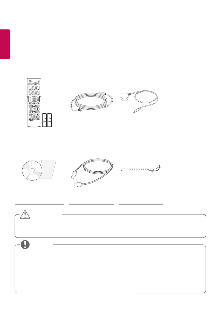
Accessories
Please check whether all the components are included in the box before using the product. If there are any
missing components, contact the retail store where you purchased the product. The illustrations in this manual
may differ from the actual product and accessories.
Remote Control,
Batteries (AAA) 2 EA
CD (Owner’s Manual) /
Card
Power Cord IR & Light Sensor
HDMI Cable Mounting Cable Tie
CAUTION
• Always use genuine components to ensure safety and product performance.
• The product warranty will not cover damage or injury caused by the use of counterfeit components.
NOTE
• The accessories provided with your product may vary depending on the model or region.
• Product specifications or contents in this manual may be changed without prior notice due to
upgrade of product functions.
• SuperSign Software & Manual
- Downloading from the LG Electronics website.
- Visit the LG Electronics website (www.lgecommercial.com/supersign) and download the latest
software for your model.
ASSEMBLY AND PREPARATION
5
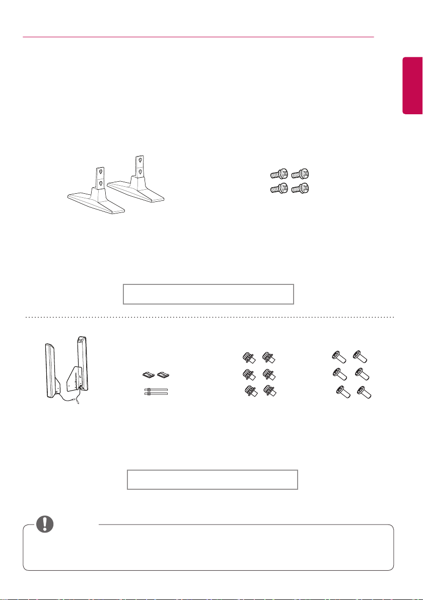
Optional Accessories
Without prior notice, optional accessories are subject to change to improve the performance of the
product, and new accessories may be added. The illustrations in this manual may differ from the actual
product and accessories.
Stand
ST-200T
Diameter 4.0 mm x Pitch 0.7 mm x
Length 10 mm (including spring washer)
Stand kit
Screws
ENGLISH
Speakers
SP-2100
Cable Holders/
Cable Ties
Screws
Diameter 4.0 mm x Pitch
0.7 mm x Length 8 mm
(including spring washer)
Screws
Diameter 4.0 mm x Pitch
1.6 mm x Length 10 mm
Speaker kit
NOTE
• Cable holder/Cable tie may not be available in some areas or for some models.
• Optional accessories are available for some models. If necessary, please purchase them separately.
6
ENGLISH
ASSEMBLY AND PREPARATION
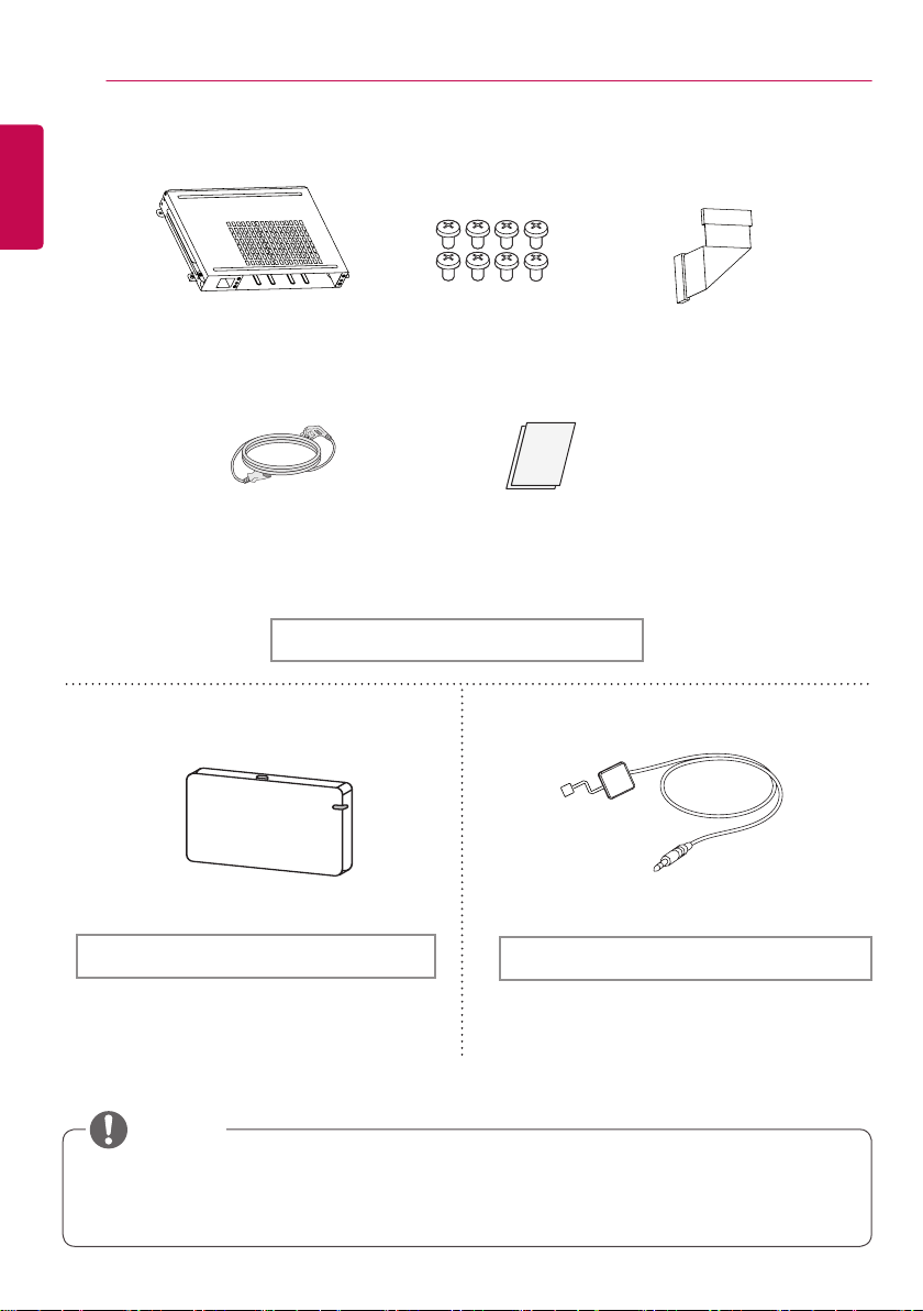
KT-OPSA
Power Cord
AN-WF500
Wi-Fi Dongle kit
Screws
Card (Easy Setup Guide)
OPS kit
Connecting
Cable
KT-SP0
Pixel sensor kit
NOTE
• Optional accessories are available for some models. If necessary, please purchase them separately.
• Pixel sensor is sold separately. You can obtain additional accessories from your local retail store.
ASSEMBLY AND PREPARATION
7
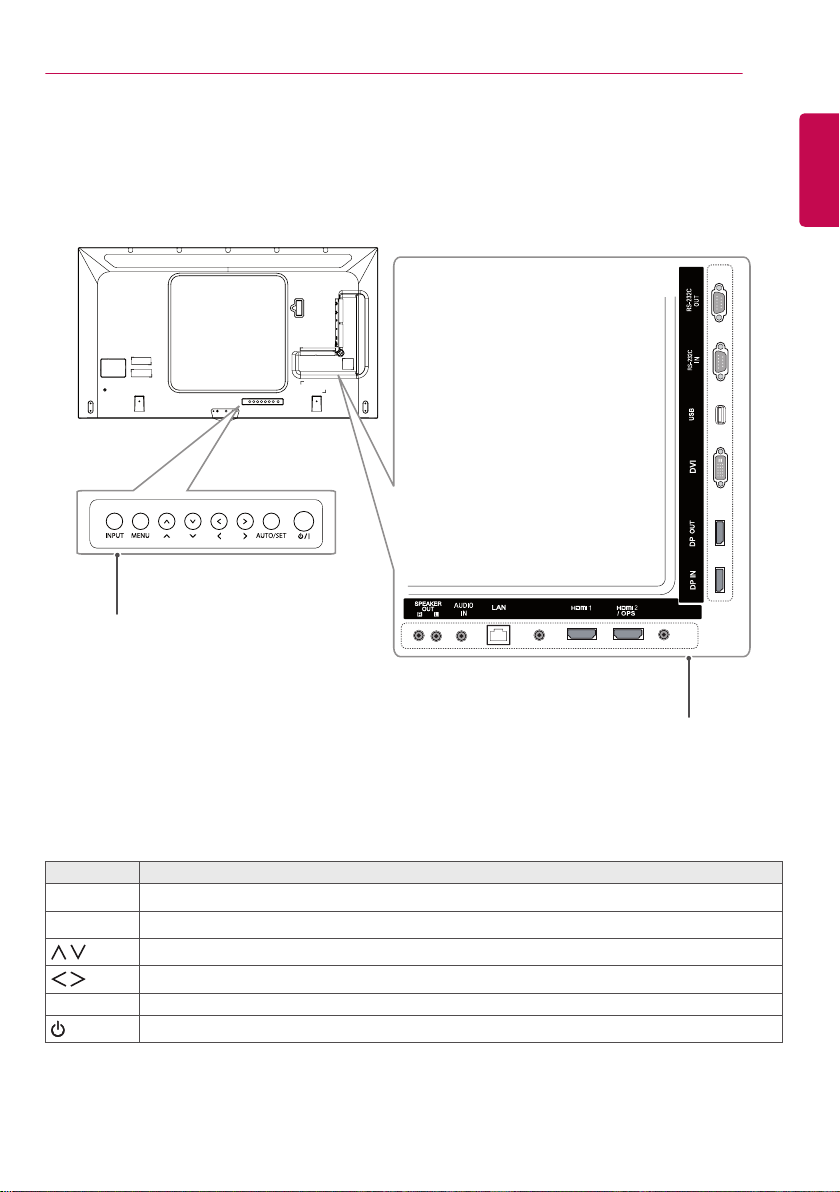
Parts and Buttons
Buttons
PIXEL
SENSOR
___
3.3V 0.25mA
---
IR&LIGHT
SENSOR
ENGLISH
Buttons Description
INPUT Changes the input source.
MENU Accesses the main menus, or saves your input and exits the menus.
Adjust the up and down.
Moves left and right.
AUTO/SET Displays the current signal and mode.
/ I
Turns the power on or off.
Connection
Panel
ASSEMBLY AND PREPARATION
8
ENGLISH
Connecting the Stand
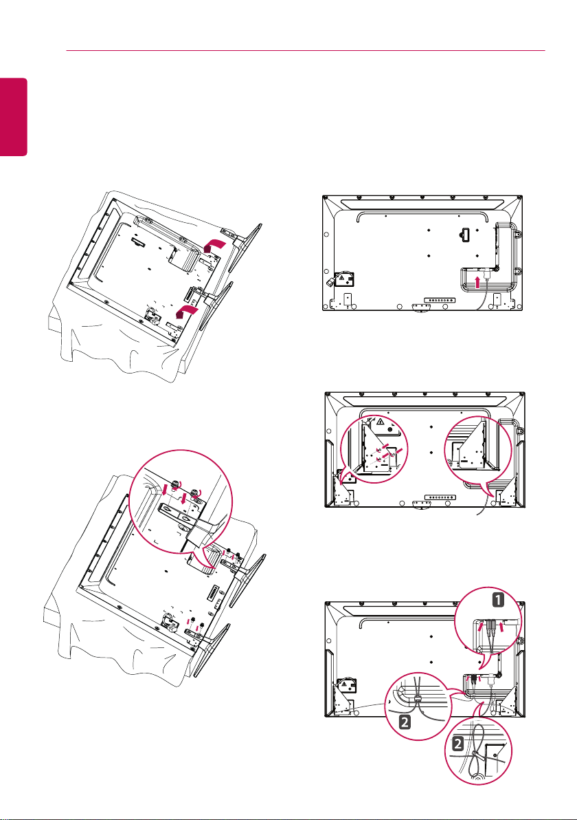
Connecting the Speakers
- For certain models only.
- The image may be different according to the
model
1 Place a soft cloth on the table and place the
product with the screen facing downward.
2 Use the screws to secure the stand to the
back of the product as shown below.
- For certain models only.
- The image may be different according to the
model.
1 Connect an input signal cable before
installing the speakers.
2 Mount the speakers by using screws as
shown below. Make sure the power cable is
disconnected before making a connection.
3 Connect the speaker cables noting the
correct polarity. Use cable holders and cable
ties to organize the speaker cables.
ASSEMBLY AND PREPARATION
PIXEL
SENSOR
IR&LIGHT
SENSOR
3.3V 0.25mA
___
---
9
NOTE
• Please turn off the power before removing
the cable. Connecting or removing the
speaker cable while turned on may result in
no sound.
Connecting IR & Light Sensor
When you connect the cable to the product,
the feature for receiving remote control signals
is activated. The IR & light sensor is magnetic.
Attach it to the front edge of the product for use.
[Front]
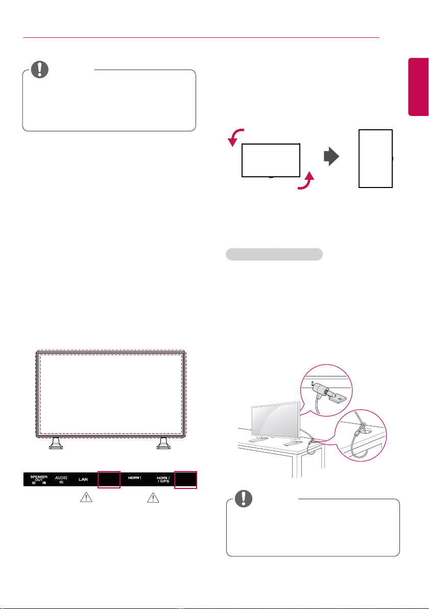
Portrait Layout
When installing in a portrait layout, rotate the
monitor counterclockwise 90 degrees (when
facing the screen).
Using Kensington Lock
The Kensington security system connector is
located at the back of the monitor. For more
information on installation and use of this
system, refer to the manual provided with the
Kensington security system or visit
kensington.com
.
Connect the Kensington security system cable
between the monitor and a table.
http://www.
ENGLISH
CAUTION
CAUTION
NOTE
• The Kensington security system is optional.
You can obtain additional accessories from
most electronics retail stores.
ASSEMBLY AND PREPARATION
10
ENGLISH
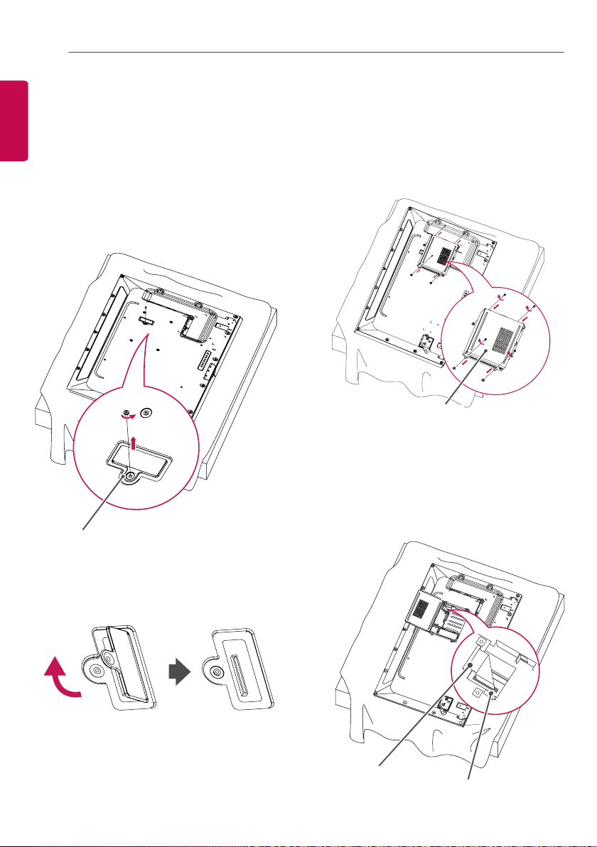
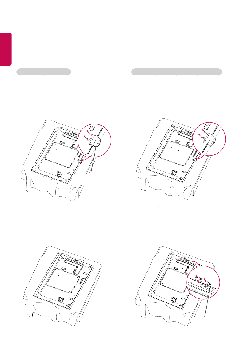
Connecting the OPS
- For certain models only.
- The image may be different according to the
model.
1 Lay a clean cloth on the floor, put the
monitor on it with the screen facing
downward, and then remove the screws
from the OPS hole cover on the rear of the
monitor with a screwdriver.
OPS Hole Cover
3 Align the KT-OPSA along the four screw
holes on the rear of the set and attach it
to the rear of the set using the four screws
provided.
KT-OPSA
4 Open the top cover of the KT-OPSA and
connect the cable provided to the connector
inside the set and the connector on the KT-
OPSA.
2 Lift the left side (round part) of the OPS hole
cover. Remove the cover.
Connector on
the KT-OPSA
Connector inside the set
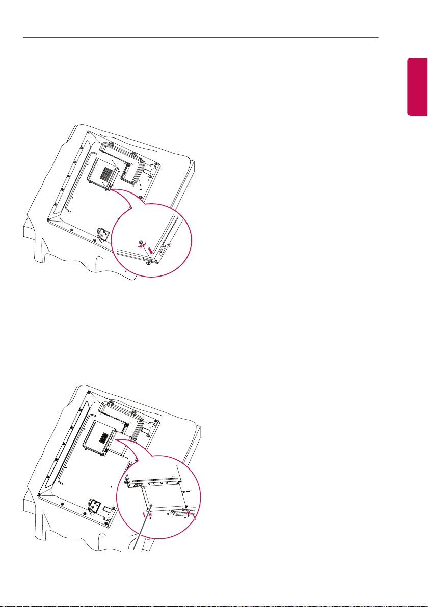
5 Close the top cover of the KT-OPSA and
tighten it on the left and right with the two
screws provided.
ASSEMBLY AND PREPARATION
11
ENGLISH
6 Insert the OPS Player (sold separately) into
the bottom hole of the KT-OPSA and finish
the installation by tightening the two screws
provided on the bottom.
OPS Player
ASSEMBLY AND PREPARATION
12
ENGLISH
Attaching and Removing the LG Logo Bracket
- For certain models only.
- The image may be different according to the model.
Removing the LG Logo
1 Lay a clean cloth on the floor, and then put
the monitor on it with the screen face down.
Remove the two screws that secure the LG
Logo Bracket to the bottom of the rear side
of the monitor using a screwdriver.
LG Logo Bracket
2 After removing the screws, remove the
LG Logo. When re-attaching the LG Logo,
follow the process in reverse order.
Attaching the LG Logo on the right side
1 Lay a clean cloth on the floor, and then put
the monitor on it with the screen face down.
Remove the two screws that secure the LG
Logo Bracket to the bottom of the rear side
of the monitor using a screwdriver.
2 After removing the screws, remove the LG
Logo. Attach the LG Logo Bracket with the
two screws, aligning it with the holes at the
right side.
Hole

ASSEMBLY AND PREPARATION
13
Installing on a Wall
For proper ventilation, allow a clearance of 10
cm on each side and from the wall. Detailed
installation instructions are available from your
dealer, see the optional Tilt Wall Mounting
Bracket Installation and Setup Guide.
10 cm
10 cm
10 cm
10 cm
To install your monitor on a wall, attach a wall
mounting bracket (optional part) to the back of
the monitor.
Make sure that the wall mounting bracket is
securely fixed to the monitor and to the wall.
1 Use only screws and wall mounting brackets
that conform to VESA standards.
2 Screws which are longer than standard
length may damage the inside of the
monitor.
3 A non-VESA standard screw may damage
the product and cause the monitor to fall.
LG Electronics is not liable for any accidents
related to the use of non-standard screws.
4 Please use VESA standard as below.
• 785 mm and above
* Fixing screws: Diameter 6.0 mm x Pitch
1.0 mm x Length 12 mm
10 cm
CAUTION
• Disconnect the power cord before moving or
installing the monitor to avoid risk of electric
shock.
• If you install the monitor on a ceiling
or slanted wall, it may fall and result in
injury. Use an authorized LG wall mount
and contact your local dealer or qualified
personnel to assist with the installation.
• Do not over tighten the screws as this may
damage the monitor and void your warranty.
• Use only screws and wall mounting brackets
that meet the VESA standard. Any damage
or injuries caused by misuse or use of
improper accessories are not covered by the
warranty.
• To prevent injury, this apparatus must be
securely attached to the wall in accordance
with the installation instructions. (This
pertains only to Australia and New Zealand.)
NOTE
• The wall mount kit includes the installation
guide and all necessary parts.
• The wall mounting bracket is optional. You
can obtain additional accessories from your
local dealer.
• The length of screws required may differ
depending on the wall mount. Be sure to
use the correct length.
• For more information, please refer to the
guide provided with the wall mount.
ENGLISH
785 mm
ASSEMBLY AND PREPARATION
14
ENGLISH
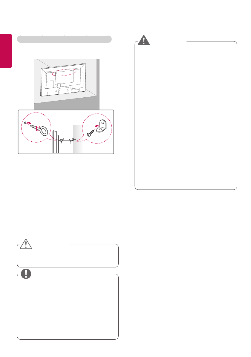
Securing the monitor to a wall (optional)
Procedure may differ depending on the model.
1 Insert and tighten the eyebolts, or brackets
and bolts on the back of the monitor.
- If there are already bolts inserted in the
eyebolts’ position, remove the other bolts
first.
2 Mount the wall brackets with the bolts to the
wall. Match the location of the wall bracket
and the eyebolts on the rear of the monitor.
3 Connect the eyebolts and wall brackets
tightly with a sturdy cord.
Make sure the securing cord is horizontal
with the flat surface.
WARNING
• If the monitor is not positioned in a
sufficiently stable location, there is a
danger that it will fall. Many injuries,
particularly to children, can be avoided by
taking simple precautions such as:
»» Using cabinets or stands
recommended by the manufacturer.
»» Only using furniture that can safely
support the monitor.
»» Ensuring the monitor is not
overhanging the edge of the supporting
furniture.
»» Not placing the monitor on tall furniture
(for example, cupboards or bookcases)
without anchoring both the furniture
and the monitor to a suitable support.
»» Not placing cloth or other materials
between the monitor and supporting
furniture.
»» Educating children about the dangers
of climbing on furniture to reach the
monitor or its controls.
CAUTION
• Make sure that children do not climb on or
hang from the monitor.
NOTE
• Use a platform or cabinet that is large
and strong enough to support the monitor
securely.
• Brackets, bolts, and cords are sold
separately. You can obtain additional
accessories from your local retail store.
• The illustration shows a general example of
installation and may look different from the
actual product.
REMOTE CONTROL
15
REMOTE CONTROL
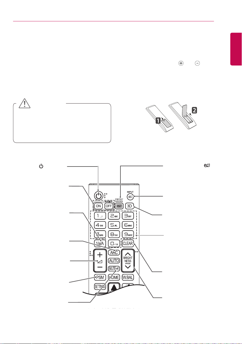
The descriptions in this manual are based on the buttons on the remote control. Please read this
manual carefully to use the monitor correctly.
To install batteries, open the battery cover, place batteries (1.5 V AAA) matching
the labels inside the compartment, and close the battery cover.
To remove the batteries, perform the installation actions in reverse. The illustrations may differ from the
actual accessories.
CAUTION
• Do not mix old and new batteries, as this
may damage the remote control.
• Be sure to point the remote control toward
the remote control sensor on the monitor.
Turns the monitor on or off.
(POWER)
MONITOR ON
Turns the monitor on.
MONITOR OFF
Turns the monitor off.
1/a/A Button
Toggles between numerical
and alphabetical.
(Depending upon the model,
this feature may not be
supported.)
ARC
Selects the Aspect Ratio
mode.
Volume Up/Down
Button
Adjusts the volume.
PSM
Selects the Picture Mode.
MUTE
Mutes all sounds.
ENERGY SAVING( )
Adjusts the brightness of
the picture to reduce energy
consumption.
INPUT
Selects the input mode.
3D
This model does not support
this.
Number and Alphabet
buttons
Enters numerical or alphabetical
characters depending upon the
setting. (Depending upon the
model, this feature may not be
supported.)
CLEAR
Deletes the entered numerical
or alphabetical character.
(Depending upon the model, this
feature may not be supported.)
BRIGHTNESS Button
Adjusts the brightness of the
display. PAGE Function is not
supported in the this model.
(Depending upon the model, this
feature may not be supported.)
and terminals to
ENGLISH
REMOTE CONTROL
16
ENGLISH
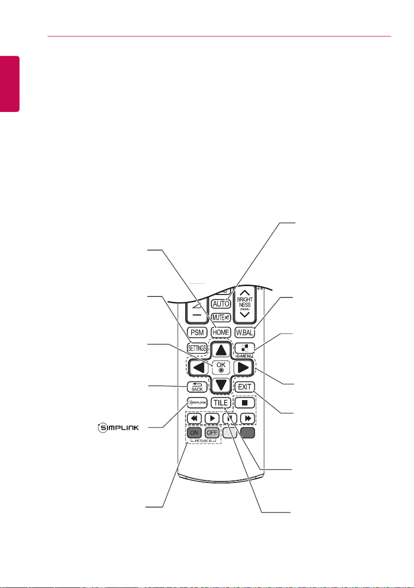
Activates the Launcher.
Accesses the main menus
or saves your input and exit
Selects menus or options and
Allows you to move back one step
in the user interaction function.
various multimedia devices to
enjoy multimedia simply by using
(Depending upon the model, this
feature may not be supported.)
confirms your input.
Allows you to control
the remote control
through the SimpLink menu.
HOME
SETTINGS
menus.
OK
BACK
AUTO
Automatically adjusts picture
position and minimizes
image instability (available
for RGB input only).
(Depending upon the model,
this feature may not be
supported.)
W.BAL
This model does not support
this.
S.MENU
SuperSign menu key
(Depending upon the model,
this feature may not be
supported.)
Navigation Buttons
Scrolls through menus or
options.
Exit
Quit all OSD tasks and
applications.
TILE
This model does not support
this.
When the Picture ID number
ID ON/OFF
matches the Set ID number, you
can control whichever monitor you
want in multi-display format.
USB Menu Control
Buttons
Controls media playback.
MAKING CONNECTIONS
17
MAKING CONNECTIONS
You can connect various external devices to your monitor. Change the input mode and select the
external device you want to connect.
For more information about external device connections, see the user manual provided with each
device.
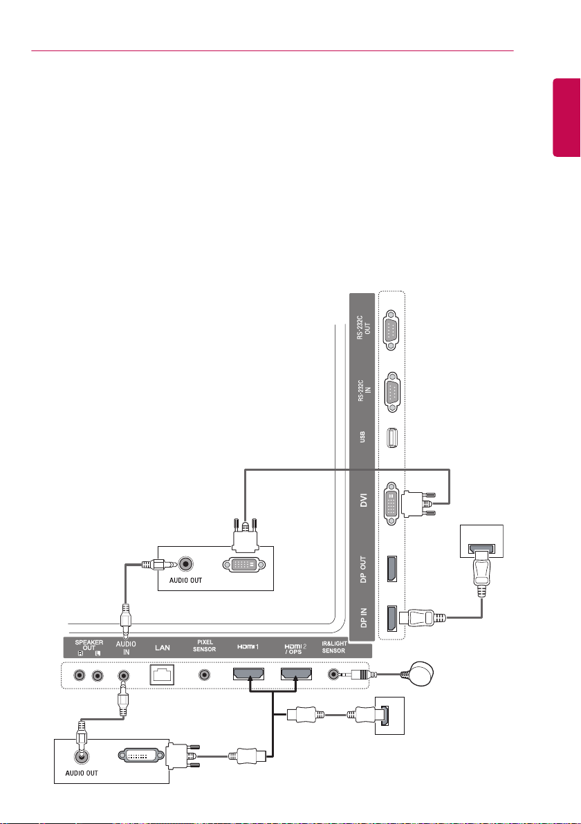
Connecting to a PC
The illustrations may differ from the actual accessories. Some of the cables are not provided.
This monitor supports the Plug & Play* feature.
* Plug & Play: a feature that enables a PC to recognize devices attached by the user without device
configuration or user intervention when powering up.
(not included)
ENGLISH
(not included)
(not included)
(not included)
DVI OUT
___
3.3V 0.25mA
---
DP OUT
DVI OUT
(not included)
HDMI
MAKING CONNECTIONS
18
ENGLISH
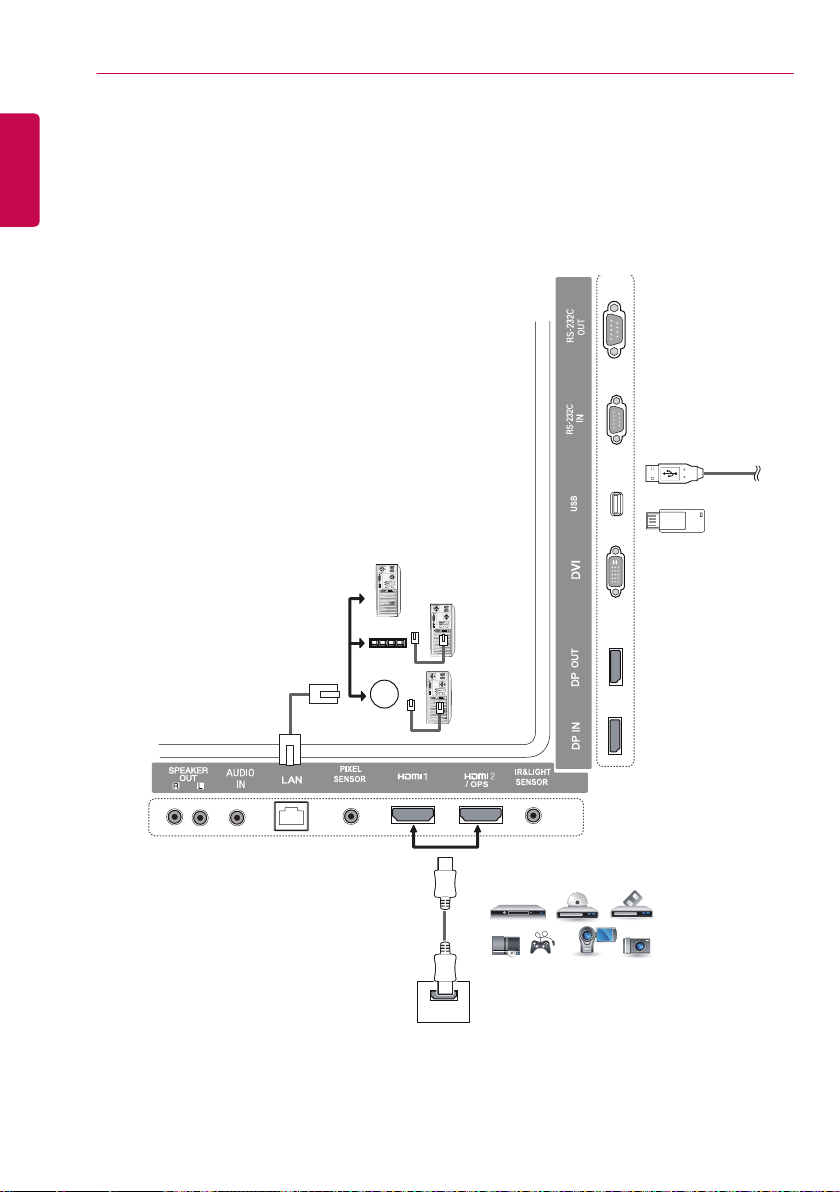
External Device Connection
Connect a HD receiver, DVD, or VCR player to the monitor and select an appropriate input mode.
The illustrations may differ from the actual accessories. Some of the cables are not provided. For
the best picture and sound quality, connecting external devices to your monitor using HDMI cables is
recommended.
ฒખ
OR
(not included)
Direct Connection/
Using the Router/
Using the Internet
USB
(not included)
___
3.3V 0.25mA
---
Network
HDMI
HD Receiver/DVD/VCR
Camcorder/Camera/Gaming Device
MAKING CONNECTIONS
19
NOTE
• For the best image quality, using the monitor with HDMI connection is recommended.
• To comply with the standard specifications of the product, use a shielded interface cable with a ferrite
core, such as a DVI cable.
• If you turn the monitor on when the set is cold, the screen may flicker. This is normal.
• Sometimes red, green, or blue spots may appear on the screen. This is normal.
• Use a High Speed HDMI
®/TM
cable.
• Use a certified cable with the HDMI logo attached. If you do not use a certified HDMI cable, the
screen may not display or a connection error may occur.
• Recommended HDMI Cable Types
- High-Speed HDMI
- High-Speed HDMI
®/TM
Cable
®/TM
Cable with Ethernet
• If you cannot hear any sound in HDMI mode please check your PC settings. Some PCs require you
to manually change the default audio output to HDMI.
• If you want to use HDMI-PC mode, you must set your PC/DTV to PC mode.
• You may experience compatibility issues if you use HDMI-PC mode.
• Make sure the power cable is disconnected.
• If you connect a gaming device to the monitor, use the cable provided with the gaming device.
• It is recommended to use the speakers that are provided as optional accessories.
• High Speed HDMI
®/TM
cables transmit a HD signal up to 1080p and higher.
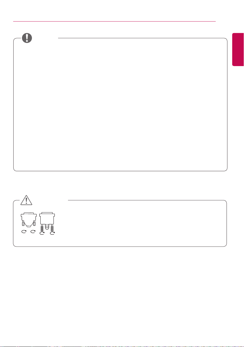
CAUTION
• Connect the signal input cable and tighten it by turning the screws clockwise.
• Do not press the screen with your finger for a prolonged period as this may
result in temporary distortion on the screen.
• Avoid displaying static images on the screen for a long period of time to
prevent image burn. Use a screensaver if possible.
• A wireless communication device near your monitor can affect the image.
ENGLISH
MAKING CONNECTIONS
20
ENGLISH
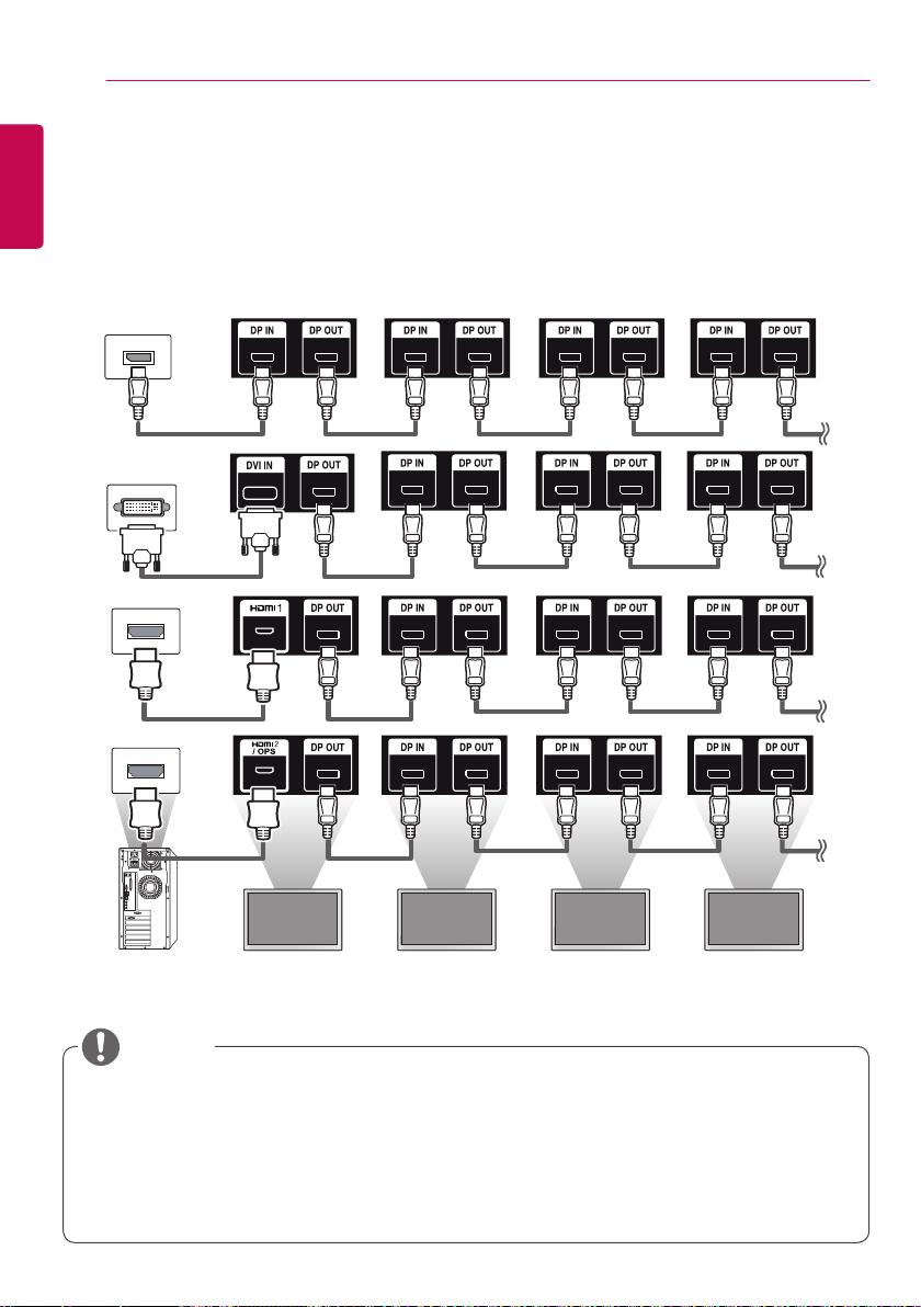
Daisy Chain Monitors
To use different products connected to each other, connect one end of the signal input cable (DP Cable)
to the DP Out connector of Monitor 1 and connect the other end to the DP In connector of the other
product.
* DP Cable - Use a DP cable that is certified to DP1.1a (SST), DP1.2 (MST) or higher.
Monitor 1 Monitor 2 Monitor 3 Monitor 4
NOTE
• If the signal is stable and there is no cable loss, in general, up to 100 monitors can be connected via
the DP Out port (at the recommended resolution). If you want to connect more than this number of
monitors, use a booster.
• If you set the tile mode using DVI or HDMI, you will not be able to watch HDCP-encrypted content.
• If the signal cable between the product and your PC is too long, make sure to use the Booster or
optical cable.

MAKING CONNECTIONS
21
Using the Multi Display Mode Function
The Multi Display Mode function displays a video signal received from DP In either in single mode
(SST: Single Stream Transport) or multi-mode (MST: Multi Stream Transport) through DP Out.
• This function can be configured in the Installation Menu (For more information, refer to the
Installation Menu manual.)
• If it is On, the image of each display is displayed in multi-mode.
• If it is Off, the image of each display is displayed in single mode.
• The multi-mode is available in a PC supporting DISPLAYPORT 1.2.
• Multi-mode can connect up to only four monitors. (at the recommended resolution)
• When this function is used, your monitor may not work properly depending on the video card. Reboot
the PC after setting the function to Off for stable screen output when not in use.
• In case of using DVI/HDMI Input to DP daisy chain, please set ‘Multi Display mode function’ to off.
ENGLISH
ENTERTAINMENT
22
ENGLISH
Using the Input List
Remote Control (HOME)
Input Mode Description
HDMI1
HDMI2/OPS
DISPLAYPORT
DVI
You can watch content on a PC,
DVD player, digital set-top box,
and other high definition devices.
CAUTION
• If the OPS kit is connected to the HDMI2/
OPS port, the HDMI2/OPS port is used as
the OPS port.
ENTERTAINMENT
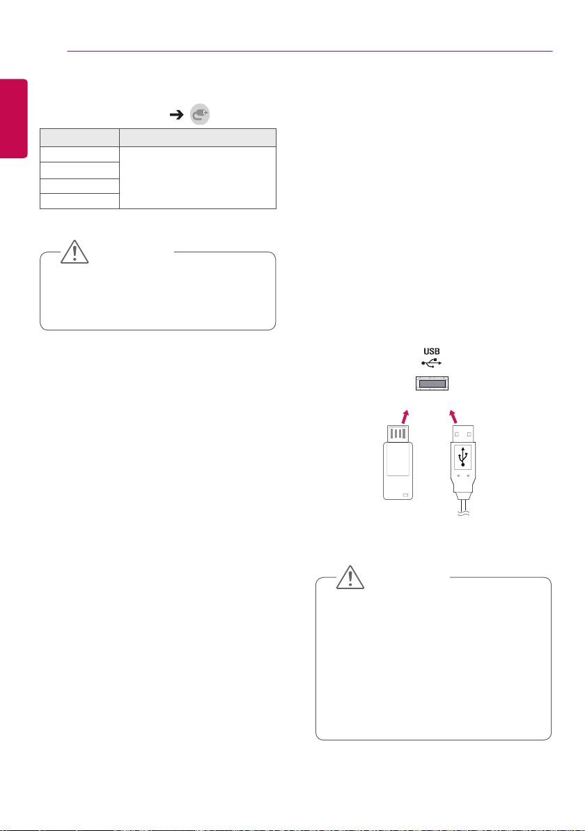
Using My Media
Connecting USB Storage Devices
Connect a USB storage device such as a USB
flash memory or an external hard drive to the
display and use multimedia features.
Connect a USB flash memory or USB memory
card reader to the display as shown in the
following illustration.
OR
CAUTION
• Do not turn off the monitor or remove a
USB storage device when the My Media
screen is activated. This could result in
loss of files or damage to the USB storage
device.
• Back up files you have saved on a USB
storage device frequently, as loss or
damage to the files may be not covered by
the warranty.
 Loading...