

LG 47LN549C, 32LN549C Owner’s Manual
OWNER’S MANUAL
LED TV*
* Disclaimer
LG LED TV applies LCD screen with LED backlights.
Please read this manual carefully before operating your set and retain it for future reference.
LN54**
LP36**
LP62**
www.lg.com

<![endif]>ENGLISH
2TABLE OF CONTENTS
TABLE OF CONTENTS
3INSTALLATION PROCEDURE
3ASSEMBLING AND PREPARING
3Unpacking
6 Separate purchase
7Parts and buttons
8 Lifting and moving the TV
9Setting up the TV
9- Attaching the stand
9Mounting on a table 12 Mounting on a wall 13 Tidying cables
13MAKING CONNECTIONS
14Antenna connection
14HDMI connection
15DVI to HDMI connection
15Component connection
16Composite connection
16RGB-PC connection
17Audio connection
17- Digital optical audio connection
17External speaker out
18Speaker output setup
18 - Volume control port
18 Network Connection
18- Connecting to a Wired Network
19- Wireless network connection
19Headphone connection
20USB connection
21REMOTE CONTROL
23 MAINTENANCE
23 Cleaning your TV
23 - Screen, frame, cabinet and stand
23 - Power cord
23TROUBLESHOOTING
24CAUTION FOR USING EZSIGN
28 LICENSES
28OPEN SOURCE SOFTWARE NOTICE
29IR CODES
30EXTERNAL CONTROL DEVICE SETUP
30 RS-232C Setup
30Type of connector; D-Sub 9-Pin Male
30RS-232C Configurations
31Communication Parameters
31Command reference list
32Transmission / Receiving Protocol
 WARNING
yy If you ignore the warning message, you may be seriously injured or there is a possibility of accident or death.
 CAUTION
yy If you ignore the caution message, you may be slightly injured or the product may be damaged.
25 SPECIFICATIONS
NOTE
yy The note helps you understand and use the product safely. Please read the note carefully before using the product.
INSTALLATION PROCEDURE / ASSEMBLING AND PREPARING |
3 |
 NOTE
NOTE
yy Image shown may differ from your TV.
yy Your TV’s OSD (On Screen Display) may differ slightly from that shown in this manual.
yy The available menus and options may differ from the input source or product model that you are using. yy New features may be added to this TV in the future.
yy The TV can be placed in standby mode in order to reduce the power consumption. And the TV should be turned off if it will not be watched for some time, as this will reduce energy consumption.
yy The energy consumed during use can be significantly reduced if the level of brightness of the picture is reduced, and this will reduce the overall running cost.
INSTALLATION PROCEDURE
1 Open the package and make sure all the accessories are included.
2Attach the stand to the TV set.
3Connect an external device to the TV set.
4Make sure the network connection is available. You can use the TV network functions only when the network connection is made. (Only LP62**)
ASSEMBLING AND PREPARING
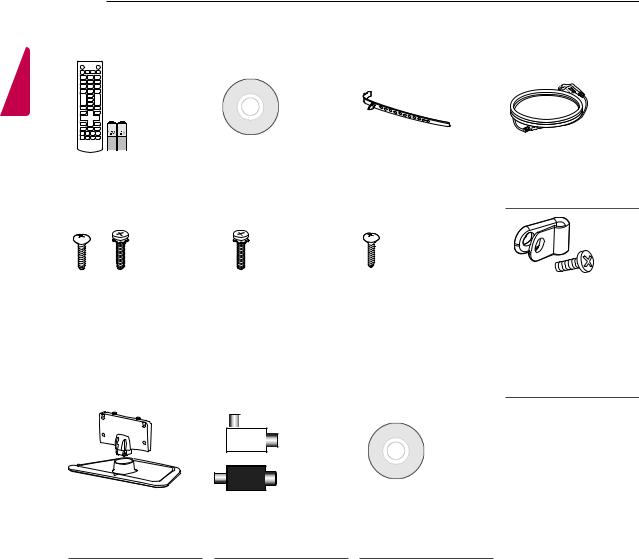
Unpacking
Check your product box for the following items. If there are any missing accessories, contact the local dealer where you purchased your product. The illustrations in this manual may differ from the actual product and item.
 CAUTION
yy Do not use any unapproved items to ensure the safety and product life span.
yy Any damages or injuries by using unapproved items are not covered by the manufacturer’s warranty. yy Some models have a thin film attached on to the screen and this must not be removed.
 WARNING
yy You need to enable easy access for connecting and disconnecting electric cables fed from the mains.
 NOTE
NOTE
yy The items supplied with your product may vary depending on the model.
yy Product specifications or contents of this manual may be changed without prior notice due to upgrade of product functions.
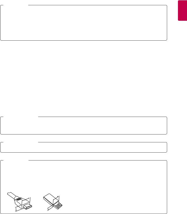
yy For an optimal connection, HDMI cables and USB devices should have bezels less than 10 mm thick and 18 mm width. Use an extension cable that supports USB 2.0 if the USB cable or USB FLASH DRIVE does not fit into your
TV’s USB port.
|
B |
B |
|
|
< |
10 mm |
|
|
|
||
|
|
*A = |
|
|
|
< |
18 mm |
A |
|
*B = |
|
|
A |
|
<![endif]>ENGLISH
4ASSEMBLING AND PREPARING
<![if ! IE]><![endif]>ENGLISH
Remote control and |
|
Owner’s manual |
|
Cable holder |
batteries (AAA) |
|
|
|
(Depending on model) |
(See p.21, 22) |
|
|
|
(See p.13) |
|
|
|
|
|
Stand Screws |
Stand Screws |
|
Desk-mount Screw |
|||||
3EA, M5 x 25 |
7EA, M4 x 14 |
|
(See p.10) |
|||||
4EA, M4 x 14 |
(Only |
|
|
|||||
(Only 60LN54**, |
32/42/47/55LN549C, |
|
|
|||||
42LN549D) |
32/42/47/55LN549E, |
|
|
|||||
(See p.9) |
LP36**, LP62**) |
|
|
|||||
|
|
(See p.9) |
|
|
||||
|
|
|
|
|
|
|
|
|
|
|
|
|
|
|
|
|
|
|
|
|
|
|
|
|
|
|
|
|
|
|
|
|
|
|
|
|
|
|
|
|
|
|
|
|
|
|
|
|
|
|
|
|
|
|
or |
|
Stand Body / Stand |
Isolator |
|
Base |
(Depending on model) |
EzSign Editor CD |
(See p.9) |
(See p.5) |
(Only LN549E) |
Power Cord
(Depending on model)
Power cable holder/ bolt
(See p.13)
ASSEMBLING AND PREPARING |
5 |
 NOTE
NOTE
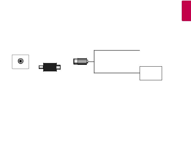
yy Antenna Isolator Installation Guide
-- Use this to install TV in a place where there is a voltage difference between TV Set and GND of antenna signal. »» If there is a voltage difference between TV Set and GND of antenna signal, the antenna contact might be
heated and excessive heat might cause an accident.
-- You can improve the safety when watching TV by efficiently removing power voltage from TV antenna. It is recommended to mount the isolator to the wall. If it cannot be mounted to the wall, mount it on the TV. Avoid disconnecting the antenna Isolator after installation.
-- Before starting, be sure that the TV antenna is connected.
1. Connect to TV.
Wall
ANTENNA/
or
Cable / Antenna
Isolator
2. Connect to Set-Top box.
Connect one end of the isolator to cable/antenna jack and the other to TV set or set-top box.
“Equipment connected to the protective earthing of the building installation through the mains connection or through other equipment with a connection to protective earthing - and to a cable distribution system using coaxial cable, may in some circumstances create a fire hazard. Connection to a cable distribution system has therefore to be provided through a device providing electrical isolation below a certain frequency range (galvanic isolator, see EN 60728-11)”
When applying the RF Isolator, a slight loss of signal sensitivity can occur.
<![endif]>ENGLISH
<![endif]>ENGLISH
6ASSEMBLING AND PREPARING
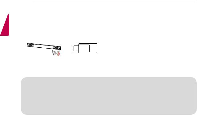
Separate purchase
Separate purchase items can be changed or modified for quality improvement without any notification. Contact your dealer to buy these items.
These devices only work with certain models.
LG Audio device |
Wireless Dongle |
|
|
|
|
|
AN-WF100 |
|
|
|
|
Compatibility |
|
LN549C, LN549D, LP36**, |
|
LN549E |
|
|
|
|
|||
|
LP62** |
|
|
||
|
|
|
|
|
|
LG Audio device |
|
• |
|
• |
|
|
|
|
|
|
|
Wireless Dongle |
|
|
|
• |
|
AN-WF100 |
|
|
|
|
|
|
|
|
|
|
|
|
|
|
|
|
|
The model name or design may be changed depending on the upgrade of product functions, manufacturer’s circumstances or policies.

ASSEMBLING AND PREPARING |
7 |
Parts and buttons
Screen |
Buttons |
|
OK
|
SETTINGS |
Speakers |
INPUT |
|
|
|
|
Remote control sensor |
|
|
|
|
|
|
|
Power indicator |
|
|
|
|
|
|
|
|
Button |
|
|
Description |
|
|
|
|
|
Scrolls through the saved programmes. |
||
|
|
|
|
|
Adjusts the volume level. |
||
|
|
|
|
|
Selects the highlighted menu option or confirms an input. |
||
SAccesses the main menu, or saves your input and exits the menus.
Changes the input source.
Turns the power on or off.
<![endif]>ENGLISH

<![endif]>ENGLISH
8ASSEMBLING AND PREPARING
Lifting and moving the TV
Please note the following advice to prevent the
TV from being scratched or damaged and for safe transportation regardless of its type and size.
yy When transporting a large TV, there should be at least 2 people.
yy When transporting the TV by hand, hold the TV as shown in the following illustration.
 CAUTION
yy Avoid touching the screen at all times, as this may result in damage to the screen.
yy It is recommended to move the TV in the box or packing material that the TV originally came in. yy Before moving or lifting the TV, disconnect the
power cord and all cables.
yy When holding the TV, the screen should face away from you to avoid damage.
yy When transporting the TV, do not expose the TV to jolts or excessive vibration.
yy When transporting the TV, keep the TV upright, never turn the TV on its side or tilt towards the left or right.
yy Do not apply excessive pressure to cause flexing /bending of frame chassis as it may damage screen.
yy Hold the top and bottom of the TV frame firmly. Make sure not to hold the transparent part, speaker, or speaker grill area.

ASSEMBLING AND PREPARING |
9 |
Setting up the TV
CAUTION
Image shown may differ from your TV.
Attaching the stand
|
Only |
|
|
32/42/47/55LN549C, |
|
|
32/42/47/55LN549E, |
|
1 |
LP36**, LP62** |
|
3EA |
||
|
||
Stand Body |
M4 x 14 |
|
Only |
||
|
||
|
60LN54**,42LN549D |
|
|
3EA |
|
|
M5 x 25 |
yy When attaching the stand to the TV set, place the screen facing down on a cushioned table or flat surface to protect the screen from scratches.
yy Make sure that the screws are inserted correctly and fastened securely. (If they are not fastened securely enough, the TV may tilt forward after being installed.)
Do not use too much force and over tighten the screws; otherwise screw may be damaged and not tighten correctly.
 NOTE
NOTE
yy Remove the stand before installing the TV on a wall mount by performing the stand attachment in reverse.
|
Stand Base |
Mounting on a table |
|
1 Lift and tilt the TV into its upright position on a table. |
|
2 |
|
|
|
-- Leave a 10 cm (minimum) space from the wall |
|
|
|
for proper ventilation. |
|
10 cm |
|
|
cm |
|
10 cm |
10 |
|
10 cm |
||
|
3
2 Connect the power cord to a wall outlet.
 CAUTION
yy Do not place the TV near or on sources of heat, as this may result in fire or other damage.
 M4 x 14
4EA
<![endif]>ENGLISH
<![endif]>ENGLISH
10 ASSEMBLING AND PREPARING
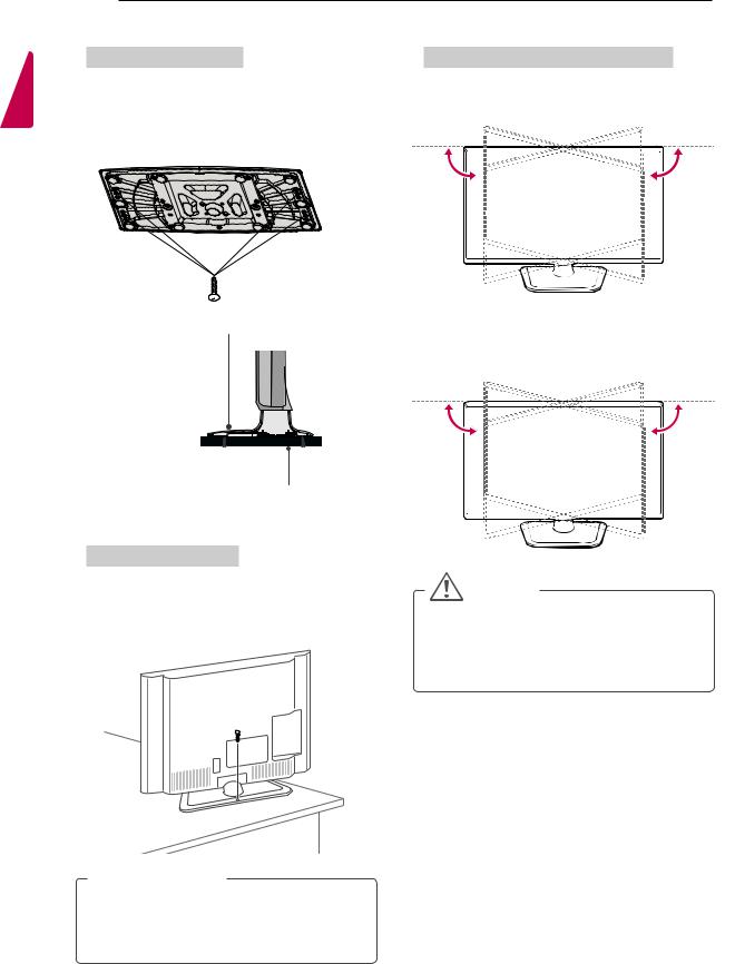
Attaching the TV to a table
(Only 39/42/47LN549C, 39/42/47LN549E, 42/47LP36**, 42/47/55LP62**)
Image shown may differ from your TV.
The TV must be attached to desk so it cannot be pulled in a forward/backward direction, potentially causing injury or damaging the product.
4-Screws
(not provided as parts of the product) Stand
Adjusting the angle of the TV to suit view
(Only 32LN54**, 32LP36**, 32LP62**)
Swivel 15 degrees to the left or right and adjust the angle of the TV to
15˚ |
15˚ |
(Only 39/42/47/55LN549C, 39/42/47/55LN549E, 42/47LP36**, 42/47/55LP62**)
Swivel 90 degrees to the left or right and adjust the angle
Table
Screws: M5 x L (*L: Table depth + 8-10 mm) ex) Table depth: 15mm, Screw: M5 x 25
Securing the TV to a table
Fix the TV to a table to prevent from tilting forward, damage, and potential injury.
To secure the TV to a table, insert and tighten the supplied screw on the rear of the stand.
 WARNING
yy To prevent TV from falling over, the TV should be securely attached to the floor/wall per installation instructions. Tipping, shaking, or rocking the TV may cause injury.
90˚ |
90˚ |
CAUTION
yy When adjusting the angle of the product, watch out for your fingers.
»»Personal injury may occur if hands or fingers are pinched. If the product is tilted too much, it may fall, causing damage or injury.
ASSEMBLING AND PREPARING |
11 |
Securing the TV to a wall
(This feature is not available for all models.)
1Insert and tighten the eye-bolts, or TV brackets and bolts on the back of the TV.
-- If there are bolts inserted at the eye-bolts position, remove the bolts first.
2Mount the wall brackets with the bolts to the wall.
Match the location of the wall bracket and the eyebolts on the rear of the TV.
3Connect the eye-bolts and wall brackets tightly with a sturdy rope.
Make sure to keep the rope horizontal with the flat
.
WARNING
yy If a television is not positioned in a sufficiently stable location, it can be potentially hazardous due to falling. Many injuries, particularly to children, can be avoided by taking simple precautions such as:
»» Using cabinets or stands recommended by the manufacturer of the television.
»» Only using furniture that can safely support the television.
»» Ensuring the television is not overhanging the edge of the supporting furniture.
»» Not placing the television on tall furniture (for example, cupboards or bookcases) without anchoring both the furniture and the television to a suitable support.
»» Not standing the televisions on cloth or other materials placed between the television and supporting furniture.
»» Educating children about the dangers of climbing on furniture to reach the television or its controls.
Using the Kensington security system
(This feature is not available for all models.)
The Kensington security system connector is located at the rear of the TV. For more information of installation and using, refer to the manual provided with the Kensington security system or visit http://www.kensington.com.
CAUTION
yy Make sure that children do not climb on or hang on the TV.
NOTE
yy Use a platform or cabinet that is strong and large enough to support the TV securely.
yy Brackets, bolts and ropes are not provided. You can obtain additional accessories from your local dealer.
Connect the Kensington security system cable between the TV and a table.
<![endif]>ENGLISH
 Loading...