

LG 47LN5400 Schematic
Internal Use Only
http://biz.lgservice.com
LED TV
SERVICE MANUAL
CHASSIS : LD31B/LD36B
MODEL : 47LN5400-CN
CAUTION
BEFORE SERVICING THE CHASSIS,
READ THE SAFETY PRECAUTIONS IN THIS MANUAL.
Printed in KoreaP/NO : MFL67730001
SAFETY PRECAUTIONS
IMPORTANT SAFETY NOTICE
Many electrical and mechanical parts in this chassis have special safety-related characteristics. These parts are identified by in the
Schematic Diagram and Exploded View.
It is essential that these special safety parts should be replaced with the same components as recommended in this manual to prevent
Shock, Fire, or other Hazards.
Do not modify the original design without permission of manufacturer.
General Guidance
An isolation Transformer should always be used during the
servicing of a receiver whose chassis is not isolated from the AC
power line. Use a transformer of adequate power rating as this
protects the technician from accidents resulting in personal injury
from electrical shocks.
It will also protect the receiver and it's components from being
damag ed by accidental shorts of the circuitry that ma y be
inadvertently introduced during the service operation.
If any fuse (or Fusible Resistor) in this TV receiver is blown,
replace it with the specified.
When replacing a high wattage resistor (Oxide Metal Film Resistor,
over 1 W), keep the resistor 10 mm away from PCB.
Keep wires away from high voltage or high temperature parts.
Before returning the receiver to the customer,
Always perform an AC leakage current check on the exposed
metallic parts of the cabinet, such as antennas, terminals, etc., to
be sure the set is safe to operate without damage of electrical
shock.
Leakage Current Cold Check(Antenna Cold Check)
With the instrument AC plug removed from AC source, connect an
electrical jumper across the two AC plug prongs. Place the AC
switch in the on position, connect one lead of ohm-meter to the AC
plug prongs tied together and touch other ohm-meter lead in turn to
each exposed metallic parts such as antenna terminals, phone
jacks, etc.
If the exposed metallic part has a return path to the chassis, the
measured resistance should be between 1 MΩ and 5.2 MΩ.
When the exposed metal has no return path to the chassis the
reading must be infinite.
An other abnormality exists that must be corrected before the
receiver is returned to the customer.
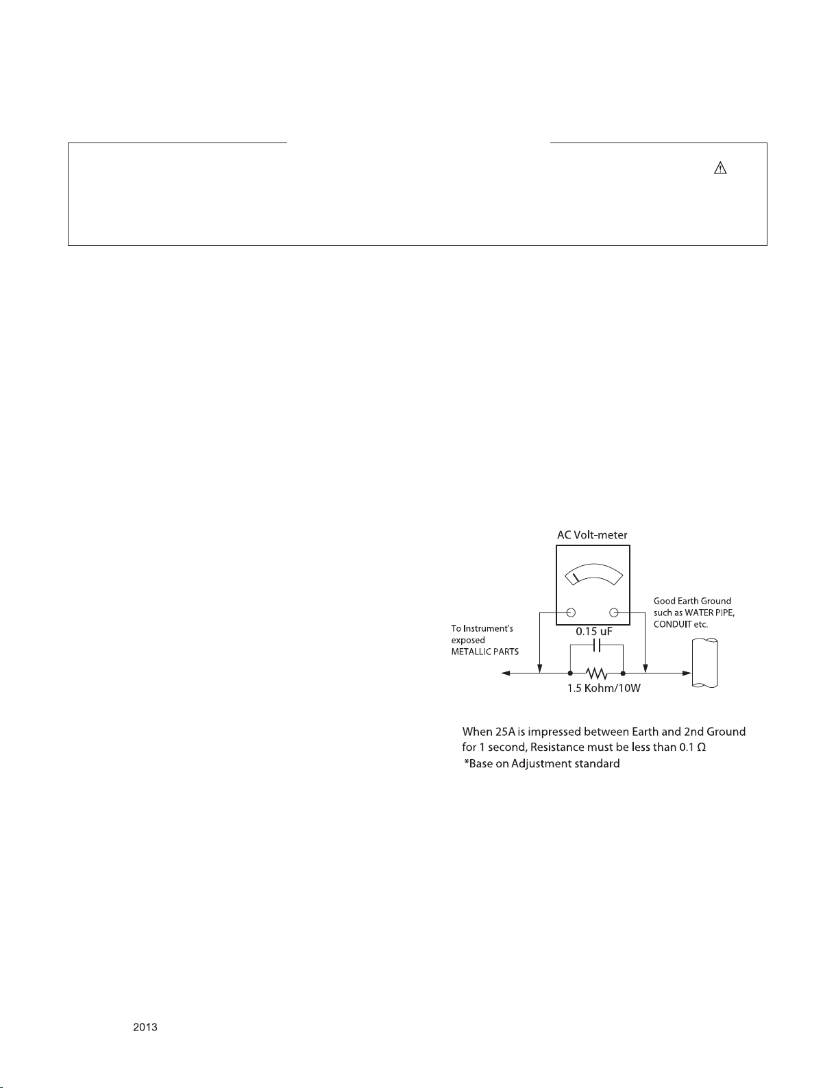
Leakage Current Hot Check (See below Figure)
Plug the AC cord directly into the AC outlet.
Do not use a line Isolation Transformer during this check.
Connect 1.5 K / 10 watt resistor in parallel with a 0.15 uF capacitor
between a known good earth ground (Water Pipe, Conduit, etc.)
and the exposed metallic parts.
Measure the AC voltage across the resistor using AC voltmeter
with 1000 ohms/volt or more sensitivity.
Reverse plug the AC cord into the AC outlet and repeat AC voltage
measurements for each expose d met allic part . Any voltage
measured must not exceed 0.75 volt RMS which is corresponds to
0.5 mA.
In case any measurement is out of the limits specified, there is
possibility of shock hazard and the set must be checked and
repaired before it is returned to the customer.
Leakage Current Hot Check circuit
Only for training and service purposes
- 3 -
LGE Internal Use OnlyCopyright © LG Electronics. Inc. All rights reserved.

SERVICING PRECAUTIONS
CAUTION: Before servicing receivers covered by this service
manual and its supplements and addenda, read and follow the
SAFETY PRECAUTIONS on page 3 of this publication.
NOTE: If unforeseen circumstances create conict between the
following servicing precautions and any of the safety precautions
on page 3 of this publication, always follow the safety precautions. Remember: Safety First.
General Servicing Precautions
1. Always unplug the receiver AC power cord from the AC power
source before;
a. Removing or reinstalling any component, circuit board
module or any other receiver assembly.
b. Disconnecting or reconnecting any receiver electrical plug
or other electrical connection.
c. Connecting a test substitute in parallel with an electrolytic
capacitor in the receiver.
CAUTION: A wrong part substitution or incorrect polarity
installation of electrolytic capacitors may result in an explosion hazard.
2. Test high voltage only by measuring it with an appropriate
high voltage meter or other voltage measuring device (DVM,
FETVOM, etc) equipped with a suitable high voltage probe.
Do not test high voltage by "drawing an arc".
3. Do not spray chemicals on or near this receiver or any of its
assemblies.
4. Unless specied otherwise in this service manual, clean
electrical contacts only by applying the following mixture to the
contacts with a pipe cleaner, cotton-tipped stick or comparable
non-abrasive applicator; 10 % (by volume) Acetone and 90 %
(by volume) isopropyl alcohol (90 % - 99 % strength)
CAUTION: This is a ammable mixture.
Unless specied otherwise in this service manual, lubrication
of contacts in not required.
5. Do not defeat any plug/socket B+ voltage interlocks with which
receivers covered by this service manual might be equipped.
6. Do not apply AC power to this instrument and/or any of its
electrical assemblies unless all solid-state device heat sinks
are correctly installed.
7. Always connect the test receiver ground lead to the receiver
chassis ground before connecting the test receiver positive
lead.
Always remove the test receiver ground lead last.
8. Use with this receiver only the test xtures specied in this
service manual.
CAUTION: Do not connect the test xture ground strap to any
heat sink in this receiver.
Electrostatically Sensitive (ES) Devices
Some semiconductor (solid-state) devices can be damaged easily by static electricity. Such components commonly are called
Electrostatically Sensitive (ES) Devices. Examples of typical ES
devices are integrated circuits and some eld-effect transistors
and semiconductor “chip” components. The following techniques
should be used to help reduce the incidence of component damage caused by static by static electricity.
1. Immediately before handling any semiconductor component or
semiconductor-equipped assembly, drain off any electrostatic
charge on your body by touching a known earth ground. Alternatively, obtain and wear a commercially available discharging wrist strap device, which should be removed to prevent
potential shock reasons prior to applying power to the unit
under test.
2. After removing an electrical assembly equipped with ES
devices, place the assembly on a conductive surface such as
aluminum foil, to prevent electrostatic charge buildup or exposure of the assembly.
3. Use only a grounded-tip soldering iron to solder or unsolder
ES devices.
4. Use only an anti-static type solder removal device. Some solder removal devices not classied as “anti-static” can generate
electrical charges sufcient to damage ES devices.
5. Do not use freon-propelled chemicals. These can generate
electrical charges sufcient to damage ES devices.
6. Do not remove a replacement ES device from its protective
package until immediately before you are ready to install it.
(Most replacement ES devices are packaged with leads electrically shorted together by conductive foam, aluminum foil or
comparable conductive material).
7. Immediately before removing the protective material from the
leads of a replacement ES device, touch the protective material to the chassis or circuit assembly into which the device will
be installed.
CAUTION: Be sure no power is applied to the chassis or circuit, and observe all other safety precautions.
8. Minimize bodily motions when handling unpackaged replacement ES devices. (Otherwise harmless motion such as the
brushing together of your clothes fabric or the lifting of your
foot from a carpeted oor can generate static electricity sufcient to damage an ES device.)
General Soldering Guidelines
1. Use a grounded-tip, low-wattage soldering iron and appropriate tip size and shape that will maintain tip temperature within
the range or 500 °F to 600 °F.
2. Use an appropriate gauge of RMA resin-core solder composed
of 60 parts tin/40 parts lead.
3. Keep the soldering iron tip clean and well tinned.
4. Thoroughly clean the surfaces to be soldered. Use a mall wirebristle (0.5 inch, or 1.25 cm) brush with a metal handle.
Do not use freon-propelled spray-on cleaners.
5. Use the following unsoldering technique
a. Allow the soldering iron tip to reach normal temperature.
(500 °F to 600 °F)
b. Heat the component lead until the solder melts.
c. Quickly draw the melted solder with an anti-static, suction-
type solder removal device or with solder braid.
CAUTION: Work quickly to avoid overheating the circuit
board printed foil.
6. Use the following soldering technique.
a. Allow the soldering iron tip to reach a normal temperature
(500 °F to 600 °F)
b. First, hold the soldering iron tip and solder the strand
against the component lead until the solder melts.
c. Quickly move the soldering iron tip to the junction of the
component lead and the printed circuit foil, and hold it there
only until the solder ows onto and around both the component lead and the foil.
CAUTION: Work quickly to avoid overheating the circuit
board printed foil.
d. Closely inspect the solder area and remove any excess or
splashed solder with a small wire-bristle brush.
Only for training and service purposes
- 4 -
LGE Internal Use OnlyCopyright © LG Electronics. Inc. All rights reserved.

IC Remove/Replacement
Some chassis circuit boards have slotted holes (oblong) through
which the IC leads are inserted and then bent at against the circuit foil. When holes are the slotted type, the following technique
should be used to remove and replace the IC. When working with
boards using the familiar round hole, use the standard technique
as outlined in paragraphs 5 and 6 above.
Removal
1. Desolder and straighten each IC lead in one operation by
gently prying up on the lead with the soldering iron tip as the
solder melts.
2. Draw away the melted solder with an anti-static suction-type
solder removal device (or with solder braid) before removing
the IC.
Replacement
1. Carefully insert the replacement IC in the circuit board.
2. Carefully bend each IC lead against the circuit foil pad and
solder it.
3. Clean the soldered areas with a small wire-bristle brush.
(It is not necessary to reapply acrylic coating to the areas).
"Small-Signal" Discrete Transistor
Removal/Replacement
1. Remove the defective transistor by clipping its leads as close
as possible to the component body.
2. Bend into a "U" shape the end of each of three leads remaining on the circuit board.
3. Bend into a "U" shape the replacement transistor leads.
4. Connect the replacement transistor leads to the corresponding
leads extending from the circuit board and crimp the "U" with
long nose pliers to insure metal to metal contact then solder
each connection.
Power Output, Transistor Device
Removal/Replacement
1. Heat and remove all solder from around the transistor leads.
2. Remove the heat sink mounting screw (if so equipped).
3. Carefully remove the transistor from the heat sink of the circuit
board.
4. Insert new transistor in the circuit board.
5. Solder each transistor lead, and clip off excess lead.
6. Replace heat sink.
Diode Removal/Replacement
1. Remove defective diode by clipping its leads as close as possible to diode body.
2. Bend the two remaining leads perpendicular y to the circuit
board.
3. Observing diode polarity, wrap each lead of the new diode
around the corresponding lead on the circuit board.
4. Securely crimp each connection and solder it.
5. Inspect (on the circuit board copper side) the solder joints of
the two "original" leads. If they are not shiny, reheat them and
if necessary, apply additional solder.
3. Solder the connections.
CAUTION: Maintain original spacing between the replaced
component and adjacent components and the circuit board to
prevent excessive component temperatures.
Circuit Board Foil Repair
Excessive heat applied to the copper foil of any printed circuit
board will weaken the adhesive that bonds the foil to the circuit
board causing the foil to separate from or "lift-off" the board. The
following guidelines and procedures should be followed whenever this condition is encountered.
At IC Connections
To repair a defective copper pattern at IC connections use the
following procedure to install a jumper wire on the copper pattern
side of the circuit board. (Use this technique only on IC connections).
1. Carefully remove the damaged copper pattern with a sharp
knife. (Remove only as much copper as absolutely necessary).
2. Carefully scratch away the solder resist and acrylic coating (if
used) from the end of the remaining copper pattern.
3. Bend a small "U" in one end of a small gauge jumper wire and
carefully crimp it around the IC pin. Solder the IC connection.
4. Route the jumper wire along the path of the out-away copper
pattern and let it overlap the previously scraped end of the
good copper pattern. Solder the overlapped area and clip off
any excess jumper wire.
At Other Connections
Use the following technique to repair the defective copper pattern
at connections other than IC Pins. This technique involves the
installation of a jumper wire on the component side of the circuit
board.
1. Remove the defective copper pattern with a sharp knife.
Remove at least 1/4 inch of copper, to ensure that a hazardous
condition will not exist if the jumper wire opens.
2. Trace along the copper pattern from both sides of the pattern
break and locate the nearest component that is directly connected to the affected copper pattern.
3. Connect insulated 20-gauge jumper wire from the lead of the
nearest component on one side of the pattern break to the
lead of the nearest component on the other side.
Carefully crimp and solder the connections.
CAUTION: Be sure the insulated jumper wire is dressed so the
it does not touch components or sharp edges.
Fuse and Conventional Resistor
Removal/Replacement
1. Clip each fuse or resistor lead at top of the circuit board hollow
stake.
2. Securely crimp the leads of replacement component around
notch at stake top.
Only for training and service purposes
- 5 -
LGE Internal Use OnlyCopyright © LG Electronics. Inc. All rights reserved.
LGE Display Division LG(51)
Establish : 12/08/31 1
Reform: 12/08/31 47
Product Specification
NetCast 4.0 Low – LC36B Product Specification
.
LC36B
LG 전자
TV Product Development.
LG ELECTRONICS Inc.
TV Research lab.
LGE Display Division LG(51)
Version
Establish : 12/08/31 2
Reform: 12/08/31 47
※ Revision history
Revision no. Effective data.
1 2012.08.31 1.00 Draft DH.LEE
2 2012.09.21 1.01 Add 47LN5400-CA Model Hun.Heo
3 2012.09.26 1.02 Add Lumi & DCR spec in 47LN5400-CA Hun.Heo
4 2012.10.08 1.03 Revise Chassis Name Hun.Heo
5 2012.10.13 1.04 Add 47LN5400-CA EEI Grade and Revise Accessory Hun.Heo
6 2012.10.17 1.05 Revise 9. Chroma & Brightness and Add 9.3 Set Optical Feature_Luminance Uniformity
7 2012.10.26 1.06 Revise 13.1 Component Video Input (Y, PB, PR)
8 2012.11.08 1.07 Add 9. Chroma & Brightness _47LN5400-CA Model Lnmi. Typ vaule and Revise 32inch Model Lumi.Uniformity Hun.Heo
9 2012.11.30 1.08 Add 32/42/55 module Spec, Modify the Optic and Display Spec Koo Jun Beom
10 2012.12.04 1.09 Revise 9.2 Set optical feature_W/B Table
NetCast 4.0 Low – LC36B Product Specification
Contents
Revised by
Hun.Heo
Hun.Heo
LG 전자

LGE Display Division LG(51)
Establish : 12/08/31 3
Reform: 12/08/31 47
NetCast 4.0 Low – LC36B Product Specification
- Contents -
1. Application Range
2. Test condition
3. Test Method
4. Electrical Specification
5. Feature and Function
6. Safety and Regulation
7. Video
8. Digital Receiver
9. Display
10. Audio
11. Power
12. Standard Level For Input Signal (Video, Audio, Y/C, Component, RGB)
13. External Input Support Format
14. USB input
15. Magic Remocon & 3D Emmiter(Spec out)
16. Wi-Fi(Spec out)
17. LED Control
18. Function and Reliability test specification
19. SET factoring condition
20. Accessories
21. EEI(Energy Efficiency Index)
LG 전자

LGE Display Division LG(51)
Chassis
Model Name
Market Place
Brand
Rem
arks
Model
Market
Appliance
Remark
Establish : 12/08/31 4
Reform: 12/08/31 47
NetCast 4.0 Low – LC36B Product Specification
1. Application range.
This spec sheet is applied to the LC36B chassis.
LC36B 47LN5400-CA China LG
LC36B 47LN5400-CA Hong Kong LG
2. Test condition
Each part is tested as below without special appointment.
2.1 Temperature : 25±5℃ (77±9℉), CST : 40±5℃
2.2 Relative Humidity : 65±10%
2.3 Power Voltage : Standard input voltage (100~240V@ 50/60Hz)
Standard Voltage of each product is marked by models
2.4 Specification and performance of each parts are followed each drawing and specification by part number in accordance with BOM.
2.5 The receiver must be operated for about5 minutes prior to the adjustment
LG 전자
3. Test method
3.1 Performance : LGE TV test method followed.
3.2 Demanded other specification
Safety : CE, IEC specification
EMC : CE, IEC
LC36B 47LN5400-CA China(DTMB/DVB-C/ PAL)
LC36B 47LN5400-CA Hong Kong(DTMB/DVB-C/ PAL)
Safety : IEC/EN60065
EMI : EN55013
LGE Display Division LG(51)
39" FHD POLA LED(CMI)
Establish : 12/08/31 5
Reform: 12/08/31 47
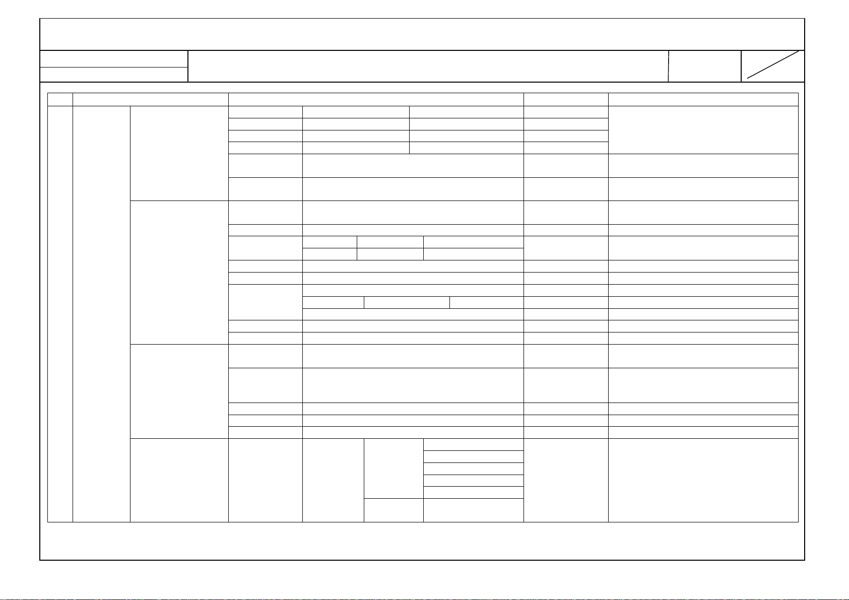
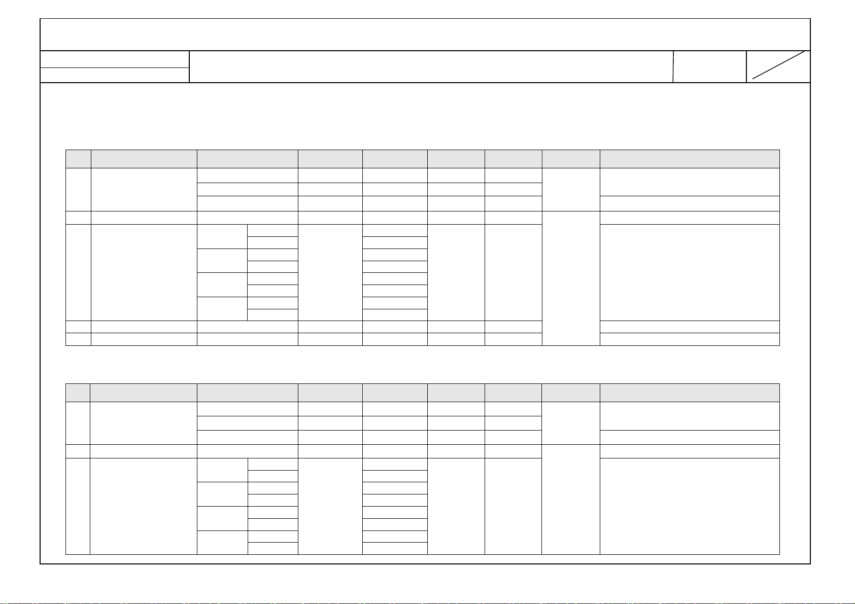
4. Electrical specification
4.1 Module general specification
No
1 Display Screen Device
2 Aspect Ratio
3 LCD Module
4 Operating Environment
5 Storage Environment
6 Input Voltage
Item Specification Measurement
NetCast 4.0 Low – LC36B Product Specification
Result Remark
32,39,42,47,55” wide Color Display Module LCD
16:9
32" FHD Direct LED (LC320DUE-SFR1)
32" HD Direct LED (LC320DXE-SFR1)
32" HD POLA LED (HC320DXN-ABFP1)
39" FHD POLA LED (HC390DUN-VCFP1)
39" FHD POLA LED (TBD)
42" FHD Direct LED (LC420DUE-SFR1)
42" FHD POLA LED (TBD)
42" FHD POLA LED (HC420DUN-SLFP1)
47" FHD Direct LED (LC470DUE-SFR1)
55" FHD POLA LED (LC550DUK-SEE1)
Temp. : 0 ~ 40 deg
Humidity : 0 ~ 85 %
Temp. : -20 ~ 60 deg
Humidity : 10 ~ 90 %
AC100 ~ 240V, 50/60Hz
Power on (White)
32" FHD Direct LED(LGD)
32" HD Direct LED(LGD)
32" HD POLA LED(BOE)
Typ : 38.6W (TBD) / Logic=6.5W, LED only=32.6W
Maker : LGD
Maker :LGD
Maker :LGD
Maker :LGD
Maker :BOE
Maker :CMI
Maker : AUO
Maker :LGD
Maker : AUO
Maker :LGD
32LN5400-CA
7
LG 전자
Power Consumption
Module Size
39" FHD POLA LED (AUO)
42" FHD Direct LED(LGD)
42" FHD POLA LED(AUO)
42" FHD POLA LED(LGD)
47" FHD Direct LED(LGD) Typ : 86.4W (TBD) / Logic=6.5W, LED only=79.9W 47LN5400-CA
55" FHD POLA LED(LGD) Typ : TBD / Logic=7.3W, LED only=TBD 55LN5400-CA
32" FHD Direct LGD
32" HD Direct LGD
32" HD POLA BOE
39" POLA CMI
39" POLA AUO
Typ : 54.7W (TBD) / Logic=6.3W, LED only=48.45W
725.2(H) × 424.4 (V) X 35.0 (B)
42LN5400-CA
32LN5400-CA
LGE Display Division LG(51)
42" Direct LGD
42"
Direct LGD
47" LGD
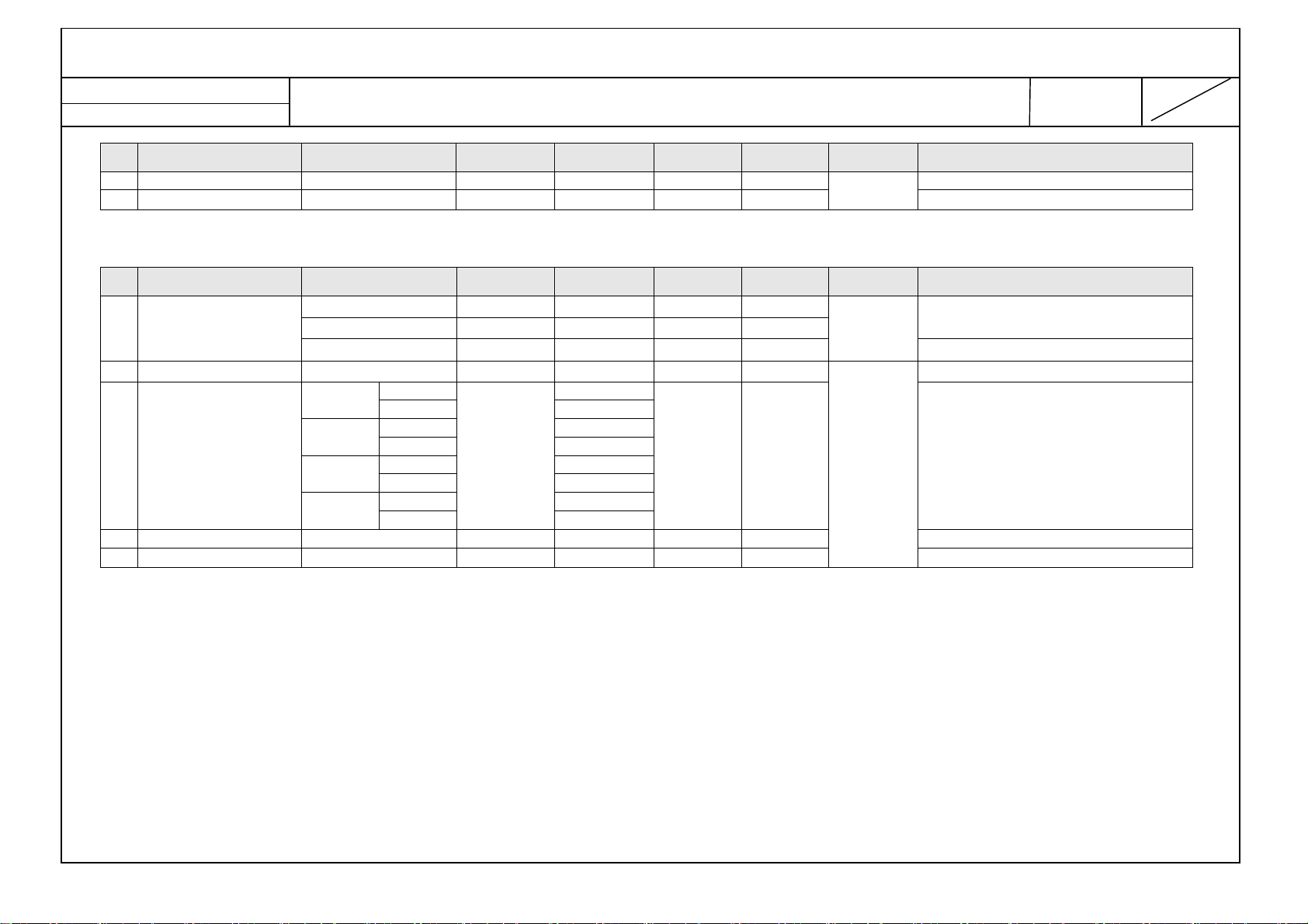
No
Item
Specification
Measure
Result
Remarks
Establish : 12/08/31 6
Reform: 12/08/31 47
No
Item Specification Measurement
42" POLA AUO
42" POLA LGD
47" Direct LGD
55" POLA LGD
32" FHD Direct LGD
32" HD Direct LGD
32" HD POLA BOE
39" POLA CMI
39" POLA AUO
Pixel Pitch
42" POLA AUO
42" POLA LGD
47" Direct LGD
55" POLA LGD
32" FHD LGD
32" HD LGD
32" HD BOE
39" CMI
Back Light
39" AUO
42" LGD
42" AUO
42" LGD
55" LGD POLA LED
NetCast 4.0 Low – LC36B Product Specification
958.2(H) X 555.8(V) X 35.0(B)
1067.6(H) X 617.4(V) X 36.5(B) 47LN5400-CA
1228.6 (H) x 701.7 (V) x1.4 (D)
0.36375 mm x 0.36375 mm
0.4833 mm x 0.4833 mm
0.5415 mm x 0.5415 mm 47LN5400-CA
0.630 mm x 0.630 mm
Direct LED
Direct LED
POLA LED
POLA LED
POLA LED
Direct LED
POLA LED
POLA LED
Direct LED
Result Remark
42LN5400-CA
55LN5400-CA
32LN5400-CA
42LN5400-CA
55LN5400-CA
4.2 Model general specification
LG 전자
4.2.1 DTV & Analog region (for Asia, Oceania, Africa, Middle East )
1.
Market China(Hong Kong) DTV & Analog - China, Hong Kong
LGE Display Division LG(51)
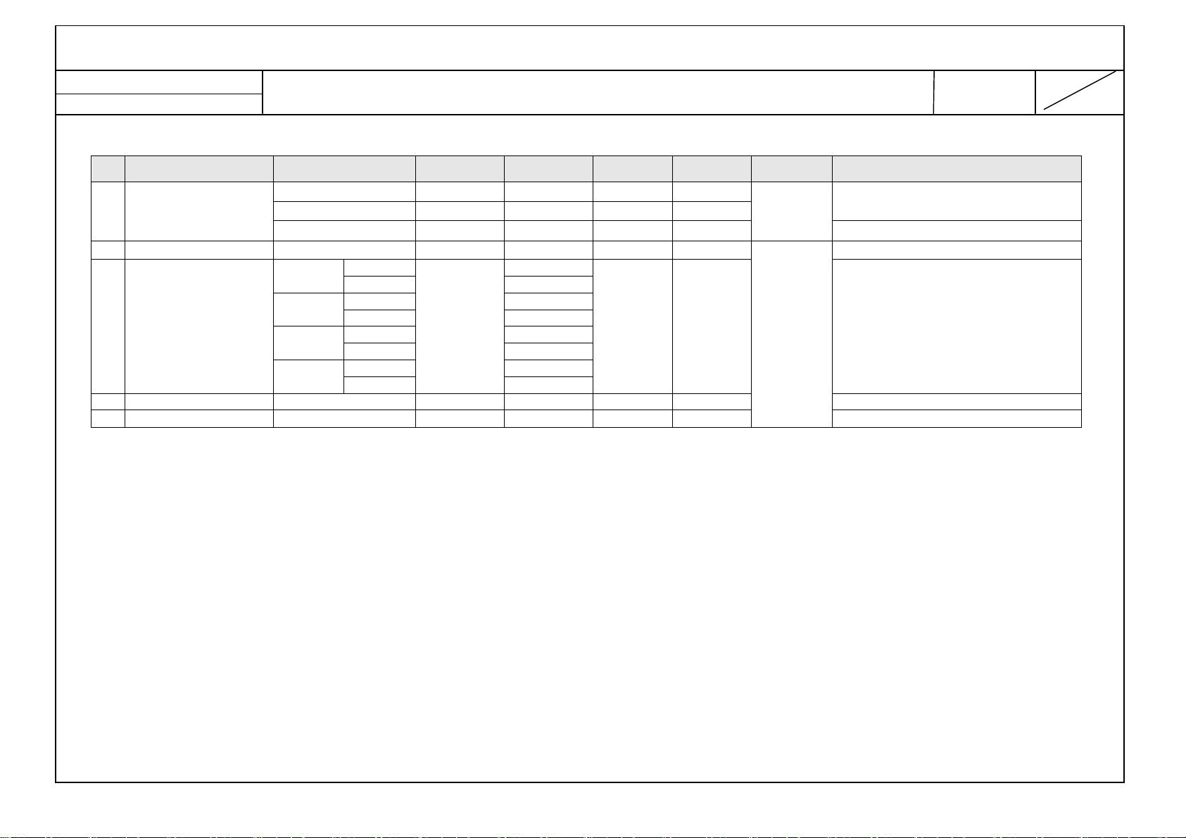
No
Item
Specification
Measure
Result
Remarks
Establish : 12/08/31 7
Reform: 12/08/31 47
1)
PAL-DK
2)
PAL-I
2.
Broadcasting system
3.
Channel Storage ATV – 135EA, DTV – 1000EA
4.
Channel Coverage
5.
Receiving system
6.
Video(Composite) Input PAL DK/I, NTSC Rear 1EA
7.
Component Input Y/Cb/Cr, Y/Pb/Pr Rear 1EA
7.
HDMI Input
3)
NTSC-M
4)
DTMB
5)
DVB-C
PAL D/K : VHF/UHF 1 ~ 62, Cable 1 ~ 41
PAL I : VHF/UHF 1 ~ 69, Cable 1 ~ 47
NTSC M : VHF/UHF 2 ~ 83, Cable 1 ~ 71
Analog : Upper Heterodyne
Digital : COFDM, QAM
HDMI1-DTV/DVI
HDMI2-DTV/DVI
NetCast 4.0 Low – LC36B Product Specification
DTMB : DMB-T + ADTB-T
75 ohm anthenna
▶ DTMB
( Carrier, Code Rate, Constellation, Frame Header, Interleaving )
*. China
- MODE1 : 3780, 0.4, 16QAM, PN945, 720, 9.626Mbps
- MODE2 : 1, 0.8, 4QAM, PN595, 720, 10.396Mbps
- MODE3 : 3780, 0.6, 16QAM, PN945, 720, 14.438Mbps
- MODE4 : 1, 0.8, 16QAM, PN595, 720, 20.791Mbps
- MODE5 : 3780, 0.8, 16QAM, PN420, 720, 21.658Mbps
- MODE6 : 3780, 0.6, 64QAM, PN420, 720, 24.365Mbps
PC(HDMI version 1.3), Support HDCP
- MODE7 : 1, 0.8, 32QAM, PN595, 720, 25.989Mbps
*. HONG KONG
- MODE : 3780, 0.4/0.6, 4/16/64QAM, PN945, 720
QPSK : 1/2, 2/3, 3/4, 5/6, 7/8
16-QAM : 1/2, 2/3, 3/4, 5/6, 7/8
64-QAM : 1/2, 2/3, 3/4, 5/6, 7/8
▶ DVB-C
- Symbolrate :
4.0Msymbols/s to 7.2Msymbols/s
- Modulation :
16QAM, 64-QAM, 128-QAM and 256-QAM
LG 전자
LGE Display Division LG(51)
No
Item
Specification
Measure
Result
Remarks
Establish : 12/08/31 8
Reform: 12/08/31 47
8.
Audio Input Component, AV L/R Input
9.
USB For My Media(Movie/Photo/Music List) or SVC 1EA(JPEG, MP3, DivX HD)
NetCast 4.0 Low – LC36B Product Specification
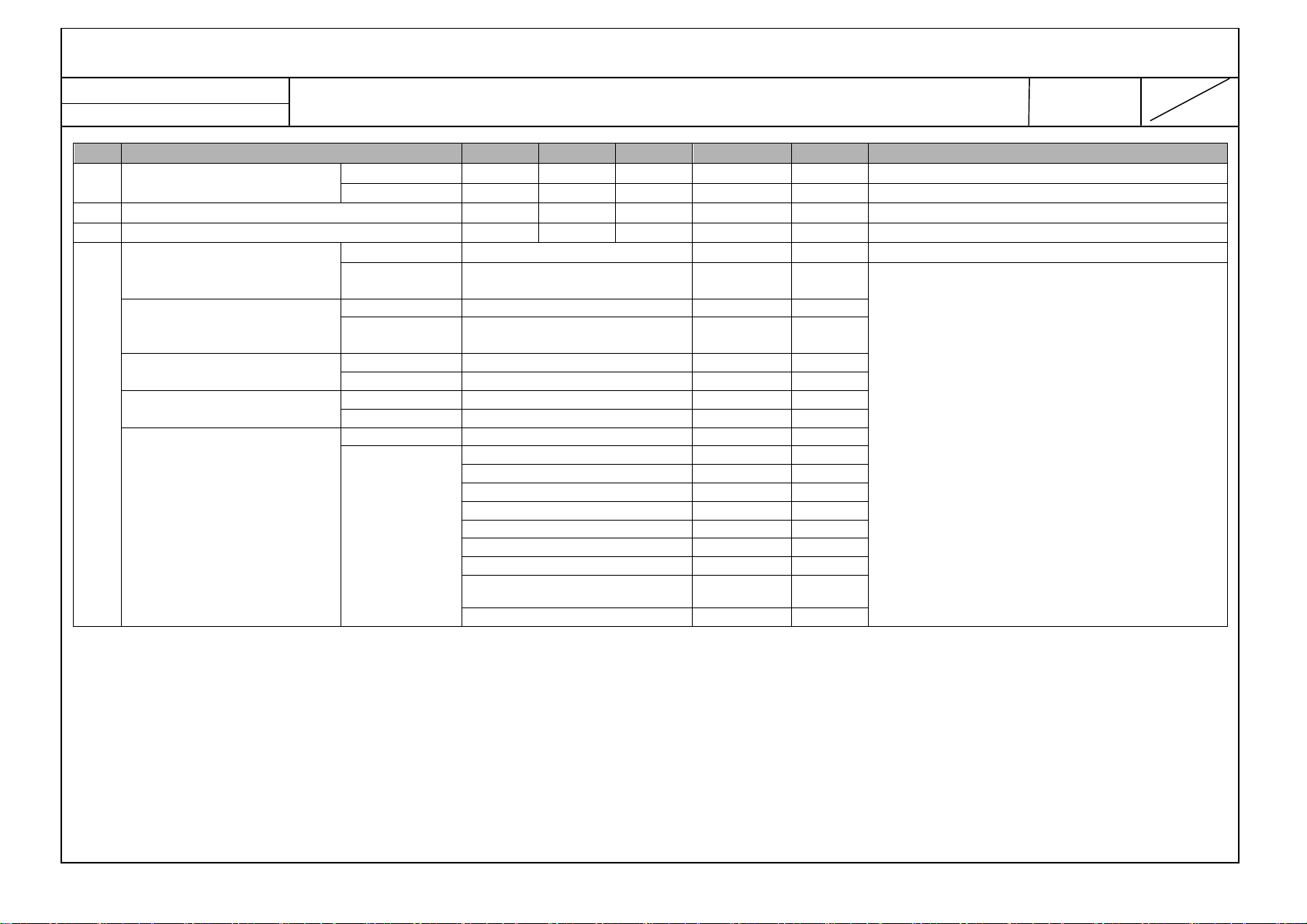
5. Feature and Function
No
1. Feature HDMI Input →HDMI Input 1,2
2. Key Tact Key
3. Menu
Item Specification Measurement Remark
USB
Y, Pb, Pr + AV input →Component + CVBS Rear
Audio Input →Component/AV Rear
Optical Digital
audio Output
(S/PDIF)
Picture Energy Saving Off/Minimum/Medium/Maximum/Screen Off
→JPEG, MP3, Upgrade (USB2.0), Divx(MPEG4)
→Digital audio out Rear
Picture Mode Vivid / Standard / Cinema / Game/isf Expert1 /isf Expert2
Vivid Standard Eco Cinema Game
Backlight 100 100 50 50 60
Contrast 95 95 95 80 90
Brightness 50 50 50 50 50
Sharpness 30 25 25 10 15
Color 70 60 65 50 55
Tint 0 0 0 0 0
Color Temp C50 C20 C50 not
activate
Advanced Control
(Standard, Game)
isf Expert1 isf Expert2
Backlight 50 50
Dynamic Contrast Off/Low/
Medium/High
Dynamic Color Off / Low / High
Skin Colour 0 ~ 5
Sky Colour -5 ~ 5
Grass Colour -5 ~ 5
Gamma Low/Medium
/High
C0 Color Temp activate at only Vivid, Standard,
Rear 1EA, Side 1EA
Side
Eco, Game
LG 전자

LGE Display Division LG(51)
Establish : 12/08/31 9
Reform: 12/08/31 47
No
Item Specification Measurement Remark
Picture Option
Digital Noise Reduction Off/Low
NetCast 4.0 Low – LC36B Product Specification
Contrast 80 80
Brightness 50 50
H Sharpness 10 10
V Sharpness 10 10
Color 50 50
Tint 0 0
Expert Control
(Cinema, isf Expert1,
isf Expert2)
Dynamic Contrast
Color Gamut Wide/Standard
Edge Enhancer Off/On
Expert Pattern Off/Pattern1/
Color Filter Off/Red/Green
Color Temperature
Gamma
Method
Pattern Outer/Inner
Points High/Low
Red -50 ~ 50
Green -50 ~ 50
Blue -50 ~ 50
Apply to all inputs
Color Management System
Color
Saturation -30 ~ 30
Tint -30 ~ 30
Luminance -30 ~ 30
Noise Reduction
Off/Low/
Medium/High
/EBU/SMPTE/
BT709
Pattern2
/Blue
Cool/Medium/
Warm1/Warm2
1.9/2.2/2.4
2Points
/10Point IRE
Off/Low
/Medium/High
/Medium/High
LG 전자
LGE Display Division LG(51)
Establish : 12/08/31 10
Reform: 12/08/31 47
No
Item Specification Measurement Remark
Black Level
Real Cinema
Motion Eye Care Off/Low /High
Picture Reset
Aspect Ratio 16:9/Just Scan/Original/Full Wide/ 4:3/Zoom/Cinema
Picture WizardII Picture setting by easy guide adjust the picture quality of
AUDIO Sound Mode Standard/Music/Cinema/Sport/Game/
Virtual Surround Off/On
Clear Voice II Off
Auto Volume Off/On
Sound Out TV Speaker/ External Speaker/(PCM) / LG Sound Bar
AV Sync. Adjust
Balance L50 ~ R50
Sound Optimizer Normal / Wall Mount Type / Stand Type
Channel Auto Tuning
Manual Tuning
Channel Edit Add or delete channels on the channel
System Color Multi/PAL-M / PAL-N / NTSC
Scan Option Primary Channel / All Channels
TIME Clock Auto Time Zone
NetCast 4.0 Low – LC36B Product Specification
Low/High
On/Off
Just Scan is supported HDMI & DTV
Zoom 1
User Setting
On Level -6 ~ +6
Off
On TV Speaker -5 ~ 15
Bypass
Start/Close
Brasilia You can select manual clock every fifty years.
Daylight
Saving
North
M.Grosso
F.Noronha
Northeast
Auto / Off / On
original image
Scan and save available channels
automatically
Tunes and stores channels manually
(Signal Strength and Signal Quality is
available on only DTV)
LG 전자

LGE Display Division LG(51)
Establish : 12/08/31 11
Reform: 12/08/31 47
No
Item Specification Measurement Remark
Off time Repeat
On time Repeat
Sleep Timer Off/10/20/30/60/90/120/180/240/
LOCK Set Password New/Confirm Default : 0000
Lock System On / Off Block Channel
Key Lock On/Off
OPTION Language Menu : Chinese/English
City/Area Mainland China(Beijing, Chengdu, Guangzhou, Hebei,
Standby Light Off/On
Hard of Hearing Off/On
NetCast 4.0 Low – LC36B Product Specification
Manual Month / Date
/ Year/Hour /
Minute
Off If On/Off Time is same, it will turn on in power
Rating 10 and above
Input Block
Subtitle : English, Mandarin(
)
语
Hefei, Wuhan, Xi An, Xiamen, Zhengzhou, Zhuhai, No
Selection) / Hong Kong
Once Hour
Daily
Mon~Fri
Mon~Sat
Sat.~Sun.
Sun.
Off
Once Hour
Daily
Mon~Fri Ext.Device
Mon~Sat DTV/TV/CATV
Sat.~Sun. 0- 100
Sun.
Minute
Minute
Input
Channel
Volume
普通话
), Cantonese(
廣東
12 and above
14 and above
16 and above
18 and above
Blocking Off
off state and turn off in power on state
LG 전자

LGE Display Division LG(51)
Establish : 12/08/31 12
Reform: 12/08/31 47
No
4. RemoconKey
Item Specification Measurement Remark
My Media
Setting
Factory Reset Yes / No
Set ID 1~99
Mode Setting Home Mode
POWER Turns the TV on or off.
TV Returns to the last TV channel.
CAPTION Hot Key - Caption function On/Off
SIMPLINK Accesses the AV devices connected to the TV;
Opens the SIMPLINK menu.
RATIO Resizes an image.
GUIDE Displays the program event according to time scheduler.
INPUT Changes the input source; Turns the TV on.
NUMBER KEYS 0~9
LIST, - (Dash) LIST: Accesses the saved channel list.
- (Dash): Inserts a dash between numbers such as 2-1 and 2-2.
Q.VIEW Alternates between the two last channels selected (pressing
repeatedly).
INFO Views the information of the current program and screen.
+VOL- Adjusts the volume level
∧CH∨
PAGE
FAV Accesses your favorite channel list.
GUIDE Access Program Guide
MUTE Mutes all sounds.
INFO Show the Program information
PICTURE Hot Key – Picture Mode
SOUND Hot Key – Sound Mode
SETTINGS Accesses the main menu.
Q. MENU Accesses the quick menu.
Navigation buttons up/down/left/right
OK Selects menus or options and confirms your input.
EXIT Clears all on-screen displays and returns to TV viewing.
AV MODE Selects an AV mode.
,
BACK
CH: Scrolls through the saved channels.
PAGE: Moves to the previous or next screen.
Scrolls through menus or options.
Returns to the previous level.
NetCast 4.0 Low – LC36B Product Specification
DivX VOD Registration / DivX Deregistration
Store Demo Demo Mode(On/Off)
LG 전자

LGE Display Division LG(51)
No Item
Min Typ Max Unit MEPS
Remarks
Establish : 12/08/31 13
Reform: 12/08/31 47
No
Item Specification Measurement Remark
SLEEP Hot Key – Sleep Timer
Color buttons These access special functions in some menus.
Control buttons Controls the Premium contents, Smart Share menus, or the
SIMPLINK compatible devices (USB,SIMPLINK).
NetCast 4.0 Low – LC36B Product Specification
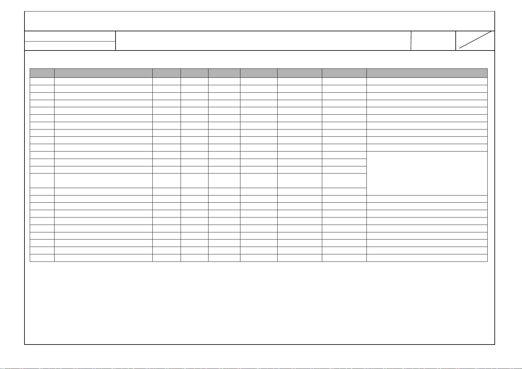
6. Safety and Regulation (Power consumption / EMC / PL)
1 Force Stability – Incline Plane Tip Test 10 12 Deg
2 Clearances & Creepage, : AC-AC 3.0 mm
3 Clearances & Creepage, : AC-GND 3.0 mm
4 Clearances & Creepage : Primary ↔ Secondary 6 mm
32LN54
39LN54
Power Consumption, Max
5
6 Power Consumption, Stand by All-inch 0.35 0.5 W
7 Energy Saving
8 Dielectric Voltage
9 Isolation Resistance 4 ∝
42LN54
47LN54 110 130
55LN54
Off - 100 Minimum 55 65 75
Medium 25 35 45
Maximum - 0 Screen Off -
1500 Vac
3000 Vac
W
%
㏁
IEC60065
Test Condition:
-LCD TV: 100% Modulation Full White
Picture mode : Vivid
* Power Consumption Max Condition:
- Video : 100% Color Bar Pattern
- Audio : Sound Max 1/8
(Non Distortion Status)
※ Dielectric Voltage
1) 3 poles
(AC↔GND)
- 1500Vac/100mA/1min (OQA)
- 1500Vac/100mA/1sec (MP)
(AC↔external interface signal line)
- 3000Vac/100mA/1min (OQA)
- 3000Vac/100mA/1sec (MP)
China: Under 0.5W
※ Refer to next page about the spec and
test condition in detail.
3 poles (GND – AC) At 100mA
3 poles (Signal – AC) At 100mA
LG 전자
LGE Display Division LG(51)
No Item
Min Typ Max Unit MEPS
Remarks
Establish : 12/08/31 14
Reform: 12/08/31 47
10 Leakage Current
11 Power cord Length 1 1.55 2
12 Sharp Edge None
Korea Compliance
UL Compliance
CSA Compliance
IEC Compliance
13
CE Compliance
UL/CSA 0.5
Etc. 0.35 V Peak
Safety K60065
EMC
Safety UL6500
EMC
Safety CSA60065
EMC GRR Part II
Safety IEC60065 Applied
EMC CISPR Applied
Safety EN60065 Applied
EMC
NetCast 4.0 Low – LC36B Product Specification
MIC Class A
MIC Class B
FCC Part 15 Class A
FCC Part 15 Class B
EN55013, EN55020 Applied
EN61000-3-2 Harmonics
EN61000-3-3 Flicker
EN61000-4-2
EN61000-4-3
EN61000-4-4
EN61000-4-5
EN61000-4-6
EN61000-4-11
mA (rms)
M
Not Applied
Not Applied
Applied
ESD
Radiated
EFT
Surge
Conducted
immunity
Applied
`
※ Energy Saving Calculating Formula
Medium = (Power consumption of Medium – Power consumption of Maximum) / (Power consumption of Off – Power consumption of Maximum)
Minimum = (Power consumption of Minimum – Power consumption of Maximum) / (Power consumption of Off – Power consumption of Maximum)
LG 전자
LGE Display Division LG(51)
Establish : 12/08/31 15
Reform: 12/08/31 47
NetCast 4.0 Low – LC36B Product Specification
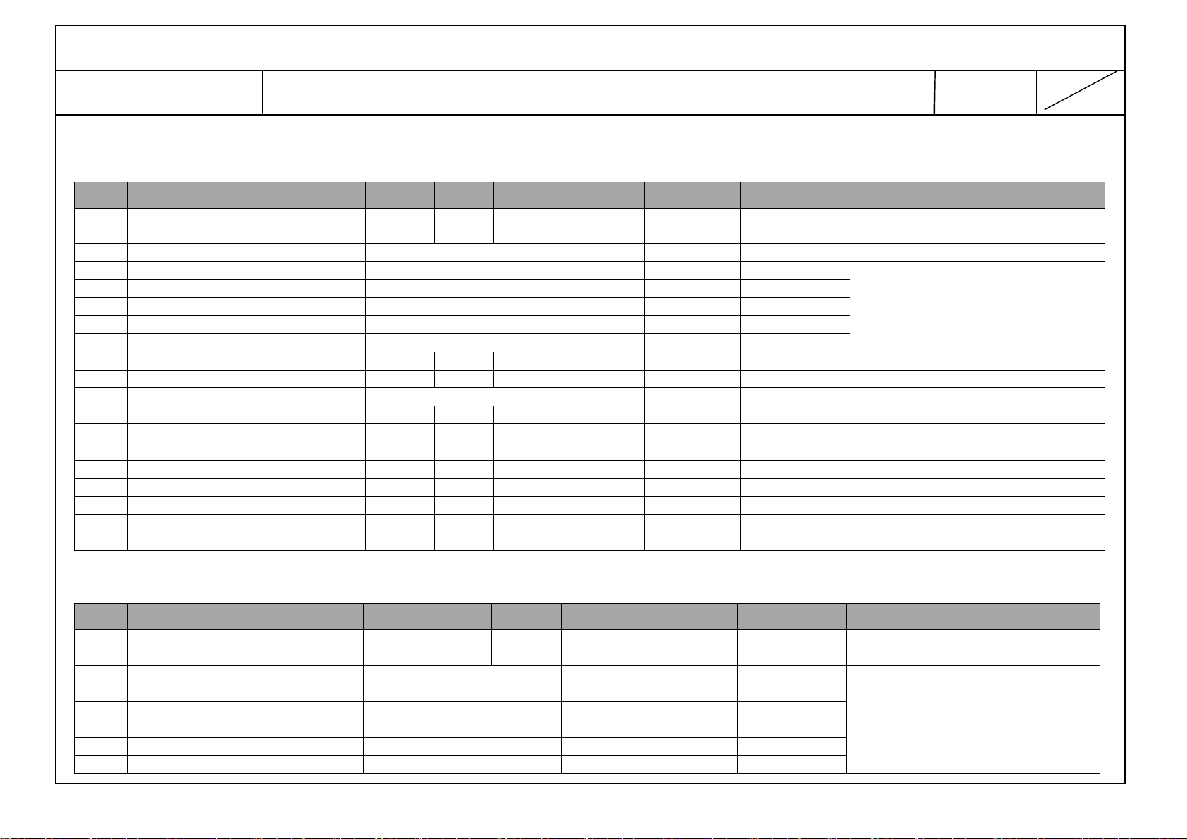
7. Video
No Item Min Typ Max Unit Remarks
1. IF Rejection Ratio -13.0 dB
2. Image Rejection Ratio -13.0 dB
3. Adjacent CH Rejection, Upper -6.0 dB
4. Adjacent CH Rejection, Lower -13.0 dB
5. Sync Level 35 %
6. Color 7 %
7. AFT -1.5 +1.5 MHz
8. AGC speed 100 Hz
9. Sub Carrier Pull In Range -450 +450 Hz
10. Sub Carrier Delay -1.5 +1.5 usec
11. AV Video Out Level 0.85 1.0 1.15 Vpp
12. AV Video Sync Out Level 0.25 0.3 0.35 Vpp
13. AV Burst Out Level 0.15 0.3 0.35 Vpp
14.
15. AV Video Out S/N 40.0 dB
16. Color Distortion, DG 10 %
17. Color Distortion, DP 10 deg
18. Color S/N, AM 43 dB
19. Color S/N, PM 43 dB
20. AV Video In Level 0.85 1 1.15 Vpp
21. AV Sync In Level 0.25 0.3 0.35 Vpp
22. AV Burst In Level 0.15 0.3 0.35 Vpp
23. AV Video In Impedance 100kHz 67.5 75 82.5 Ohm
24. AV Video In Impedance 2MHz 67.5 75 82.5 Ohm
AV Video Out Frequency
Characteristic
3.0 MHz
※ LC36B can’t support
AV out function.
LG 전자
LGE Display Division LG(51)
Establish : 12/08/31 16
Reform: 12/08/31 47
NetCast 4.0 Low – LC36B Product Specification
8. Digital Receiver
8.1 Digital Recriver ( DTMB : ADTB-T ) : C=1, 16QAM, 0.8, PN=595, M=720
No Item Min Typ Max Unit
1 Frequency Range
2 Input Impedance 75 Ω
3 Carrier C=1
4 Modulation 4QAM, 16QAM, 32QAM
5 Code Rate 0.8
6 Frame Header PN595
7 Interleaver M=720
8-1 RF Sensitivity(VHF) -85 -25 dBm
8-2 RF Sensitivity(UHF) -83 -25 dBm
9 Channel Offsets ±150 kHz
10 C/N with AWGN 14 dB
11-1 PAL CCI Protection (Analog) 2 dB
11-2 PAL CCI Protection (Digital) 14 dB
12-1 PAL ACI protection(Analog Lower) -37 dB
12-2 PAL ACI protection(Analog Upper) -36 dB
12-3 PAL ACI protection(Digital) -28 dB
13 Ricean channel C/N
14 Rayleigh channel C/N
474
52.5
15 dB
18 dB
866
219
MHz
Remarks
UHF BAND
VHF BAND
8-2.Digital Receiver (DTMB : DMB-T) : C=3780, 16QAM, 0.8, PN=420, M=720
No Item Min Typ Max Unit
1 Frequency Range
2 Input Impedance 75 Ω
3 Carrier C=3780
4 Modulation 16QAM, 64QAM
5 Code Rate 0.4, 0.6, 0.8
6 Frame Header PN420, PN945
7 Interleaver M=720
474
52.5
866
219
MHz
UHF BAND
VHF BAND
Remarks
LG 전자

LGE Display Division LG(51)
No Item
Min Typ Max Unit Remarks
Establish : 12/08/31 17
Reform: 12/08/31 47
8-1 RF Sensitivity(VHF) -85 -25 dBm
8-2 RF Sensitivity(UHF) -83 -25 dBm
9 Channel Offsets ±150 kHz
10 C/N with AWGN 14 dB
11-1 PAL CCI Protection (Analog) 2 dB
11-2 PAL CCI Protection (Digital) 14 dB
12-1 PAL ACI protection(Analog Lower) -37 dB
12-2 PAL ACI protection(Analog Upper) -36 dB
12-3 PAL ACI protection(Digital) -28 dB
13 Ricean channel C/N
14 Rayleigh channel C/N
NetCast 4.0 Low – LC36B Product Specification
15 dB
18 dB
8-3. Digital Receiver (DVB-C)
1. Frequency Range 52.5 866 MHz
2. Input Impedance 75 Ω
3. Symbol Rate
4. Modulation 16, 32, 64, 128, 256QAM
5 RF Sensitivity 47 70 dBuV
6. C/N with AWGN
4000 Ks/s~7200 Ks/s
16QAM 20.5 dB
32QAM 26.5 dB
64QAM 29.5 dB
128QAM 31.5 dB
256QAM 32.5 dB
LG 전자
LGE Display Division LG(51)
Establish : 12/08/31 18
Reform: 12/08/31 47
NetCast 4.0 Low – LC36B Product Specification
9. Display
9.1 Module optical specifications.( for more details, refer to the module spec.)
* 32" LGD Module (LGD, Direct LED, FHD, 60Hz) –LC320DUE-SFR1
No
1 Luminance
2 Contrast ratio CR 850 1200
3 Color coordinate
4 Color Temperature 10,000 K
5 Viewing Angle Right/Left (Up/Down) 89/89(89/89)
Item Specification Min Typ Max Unit Maker Remark
Module Max 240 300 cd/m²
TV set Max 192 240 cd/m²
White Variation 50 60 δ WHITE(9P)=Min/Max X 100(%)
R
RED
GREEN
BLUE
WHITE
x
Ry 0.330
G
0.306
x
Gy 0.588
B
0.151
x
By 0.065
W
0.281
x
Wy 0.288
Typ.
-0.03
0.644
Typ.
+0.03
2D(CR>10)
32LN5400-CA
LGD
(B/L)
LGD
(LCD)
(Center 1-point / Full White Pattern)
Full White / Full Black
* 42" LGD Module (LGD, Direct LED, FHD, 60Hz) –LC420DUE-SFR1
No
1 Luminance
2 Contrast ratio CR 850 1200
3 Color coordinate
Item Specification Min Typ Max Unit Maker Remark
Module Max 240 300 cd/m²
TV set Max 192 240 cd/m²
White Variation 60 70 δ WHITE(9P)=Min/Max X 100(%)
R
RED
GREEN
BLUE
WHITE
x
Ry 0.333
G
0.301
x
Gy 0.590
B
0.149
x
By 0.061
W
0.281
x
Wy 0.288
Typ.
-0.03
0.649
Typ.
+0.03
42LN5400-CA
LGD
(B/L)
LGD
(LCD)
(Center 1-point / Full White Pattern)
Full White / Full Black
LG 전자
LGE Display Division LG(51)
Establish : 12/08/31 19
Reform: 12/08/31 47
No
4 Color Temperature 10,000 K
5 Viewing Angle Right/Left (Up/Down) 89/89(89/89)
Item Specification Min Typ Max Unit Maker Remark
NetCast 4.0 Low – LC36B Product Specification
2D(CR>10)
* 47" LGD Module (LGD, Direct LED, FHD, 60Hz) –LC470DUE-SFR1
No
1 Luminance
2 Contrast ratio CR 1000 1200
3 Color coordinate
4 Color Temperature 10,000 K
5 Viewing Angle Right/Left (Up/Down) 89/89(89/89)
Item Specification Min Typ Max Unit Maker Remark
Module Max 240 300 cd/m²
TV set Max 192 240 cd/m²
White Variation 60 70 δ WHITE(9P)=Min/Max X 100(%)
R
RED
GREEN
BLUE
WHITE
x
Ry 0.333
G
0.301
x
Gy 0.595
B
0.149
x
By 0.061
W
0.281
x
Wy 0.288
Typ.
-0.03
0.649
Typ.
+0.03
2D(CR>10)
47LN5400-CA
LGD
(B/L)
LGD
(LCD)
(Center 1-point / Full White Pattern)
Full White / Full Black
LG 전자
LGE Display Division LG(51)
Establish : 12/08/31 20
Reform: 12/08/31 47
NetCast 4.0 Low – LC36B Product Specification
* 55" LGD Module (LGD, POLA LED, FHD, 60Hz) –LC550DUK-SEE1
No
1 Luminance
2 Contrast ratio CR 900 1200
3 Color coordinate
4 Color Temperature 10,000 K
5 Viewing Angle Right/Left (Up/Down) 89/89(89/89)
Item Specification Min Typ Max Unit Maker Remark
Module Max TBD cd/m²
TV set Max TBD cd/m²
White Variation TBD δ WHITE(9P)=Min/Max X 100(%)
R
RED
GREEN
BLUE
WHITE
x
Ry 0.343
G
0.316
x
Gy 0.595
B
0.152
x
By 0.058
W
TBD
x
Wy TBD
Typ.
-0.03
0.639
Typ.
+0.03
2D(CR>10)
55LN5400-CA
LGD
(LCD)
(Center 1-point / Full White Pattern)
Full White / Full Black
LG 전자

LGE Display Division LG(51)
Luminance (min)
C/R(min)
AV, COMPONENT, HDMI
AV, COMPONENT, HDMI
2
2
No BLU Type
FHD/HD
Freq.
Min Typ Max Remark
Establish : 12/08/31 21
Reform: 12/08/31 47
NetCast 4.0 Low – LC36B Product Specification
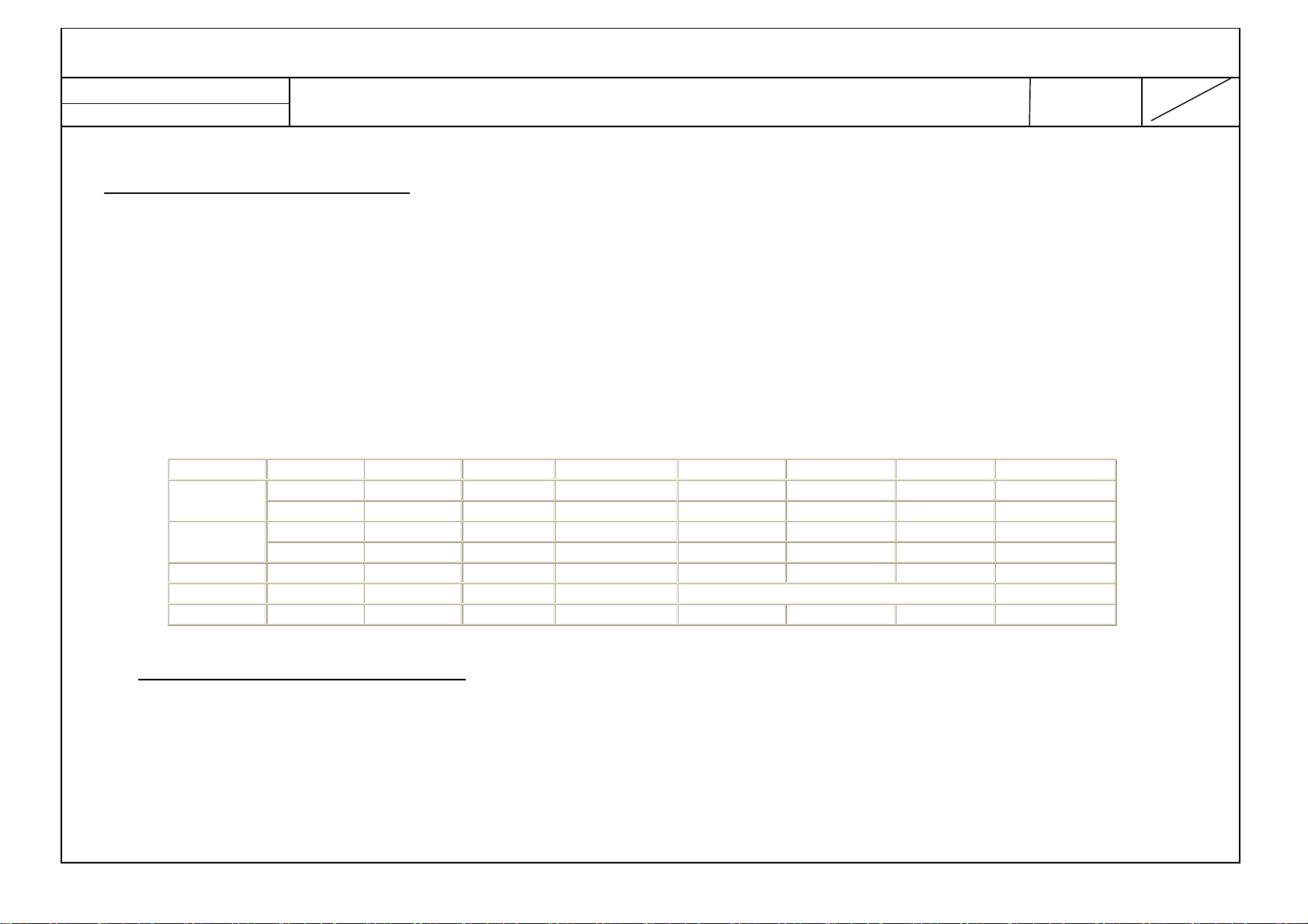
9.2 Set optical feature
9.2.1 Chroma (PSM: Vivid, Color Temperature: C50 )
– except “RGB PC Mode PSM: Standard, Color Temperature: Medium”
** The W/B Tolerance is ±0.002 for Adjustment, but for DQA ±0.015
No
1.
2.
3.
C50
(Cool)
0
(Medium)
W50
(Warm)
Item Min Typ Max Unit Remark
White Balance, X axis
White Balance, Y axis
White Balance, X axis
White Balance, Y axis
White Balance, X axis
White Balance, Y axis
0.269
0.268
0.284
0.287
0.311
0.327
0.271
0.270
0.286
0.289
0.313
0.329
0.273
0.272
0.288
0.291
0.315
0.331
W/B Variation Design(R&D) Spec : ±0.002, DQA Spec ±0.015)
26/32/42CS46, 26/32/42CS47,
32/37/42/47CS56,
26/32LS35, 26/32LS37,
32/42LS34, 32/42LM34,
32/37/42/47LS46, 47/55LM46,
32/42/47/55LM58
※ The W/B Tolerance is ±0.015 for picture
quality by DQA.
※ In the case of LED model, measure the
color temperature at the warm mode after
heat run TV more than 60 minutes at
Cinema mode.
(
9.2.2 General feature
1. Measurement Condition: Full white à Measure the black luminance after 30 seconds.
No Item module
Remark
1. 32LN5400
2. 39LN5400
3. 42LN5400
4. 47LN5400 LGD Direct 190 cd/m2 1000
5. 55LN5400 LGD POLA TBD cd/m2 900
9.2.3 Special feature (Dynamic CR – except PC mode)
1. Direct LED
LG 전자
LGD Direct
LGD(HD) Direct
BOE POLA
CMI POLA
AUO POLA
LGD Direct 190 cd/m
AUO POLA
LGD POLA
HD 50/60Hz 20,000 30,000 32LN5400
FHD 50/60Hz 24,000 30,000 32/39/42/47/55LN5400
190 cd/m
850
850
C/R except from the PC mode.
Module Min Luminance(80% of Typ) x
Decrese of W/B Adjustment(85%)
LGE Display Division LG(51)
Establish : 12/08/31 22
Reform: 12/08/31 47
NetCast 4.0 Low – LC36B Product Specification
9.2.4 Test Condition
※ Color Temperature measure standard specification
▣ Color Temperature measure specification
1) In non-impressed condition, measure White Balance displayable as much as possible LCD module.
2) Measuring instrument: CA-210 or a sort of Color Analyzer.
3) Pattern Generator : VG-828 or a sort of digital pattern generator (204 Gray)
4) Measure condition
● Test pattern: 80% Full White pattern
● SET condition : Contrast & Brightness Level Default
● Environment condition : Dark room in the non outside light
● Video menu option condition
RF
AV
Component 1080p Standard 100 W50 /M0 / C50 Off Off Off High
RGB 1024x768 Standard 100 W50 /M0 / C50 Off deactivated NA
HDMI DTV 1080p Standard 100 W50 /M0 / C50 Off Off Off Low
Signal Picture Mode Backlight Color Temp. Dynamic Contrast Dynamic Color
NTSC-M Standard 100 W50 /M0 / C50 Off Off Off Low
PAL Standard 100 W50 /M0 / C50 Off Off Off Auto
NTSC-J Standard 100 W50 /M0 / C50 Off Off Off High
PAL Standard 100 W50 /M0 / C50 Off Off Off Auto
Eye Care Black Level
※ Luminance & Contrast measure standard specification
▣ Luminance measure specification
1) In non-impressed condition, measure peak brightness displayable as much as possible LCD module.
2) Measuring instrument: CA-210 or a sort of Color Analyzer.
3) Pattern Generator : VG-828 or a sort of digital pattern generator(displayable Full White pattern)
4) A measurement condition
LG 전자
LGE Display Division LG(51)
Establish : 12/08/31 23
Reform: 12/08/31 47
● Test pattern : full white pattern(255 Gray)
● SET condition : Contrast & Brightness Level Default
● Environment condition : Dark room in the non outside light
● Video menu option condition
RF
AV
Component 1080p Standard 100 0 Off Off Off High
RGB Adjust mode à Test pattern à White.
HDMI DTV 1080p Standard 100 0 Off Off Off Low
5) Measurement
● Do heat-run LCD module at 5minutes in normal temperature (25℃) by using full white pattern of 15% signal level(38 gray level).
● Impress test pattern signal in 1/5(H) * 1/5(V) White Window of 100%(255Gray Level).
● measure 3 times brightness of central white window, and mark peak brightness in max brightness degree.
Signal Picture Mode Backlight Color Temp. Dynamic Contrast Dynamic Color
NTSC-M Standard 100 0 Off Off Off Low
PAL Standard 100 0 Off Off Off Auto
NTSC-J Standard 100 0 Off Off Off High
PAL Standard 100 0 Off Off Off Auto
NetCast 4.0 Low – LC36B Product Specification
Eye Care Black Level
● measure the same condition in video signal /RGB signal.
▣ Brightness / Contrast Tracking measure specification
1) In non-impressed condition, measure peak brightness displayable as much as possible LCD module.
2) Measuring instrument: CA-210 or a sort of Color Analyzer.
3) Pattern Generator : VG-828 or a sort of digital pattern generator (displayable Full White & 1/25 White Window pattern)
4) Measure condition
● Test pattern: in center, 1/5(H) * 1/5(V) of Window Pattern (white pattern in non-impressed condition)
● Environment condition : Dark room in the non outside light
● Video menu option condition : Shipment MODE.(In-Stop)
LG 전자
 Loading...