

LG 55LH80YD, 47LH80YD Owner’s Manual
ENGLISH
OWNER’S MANUAL
LCD TV MODELS
4477LLHH88******
5555LLHH88******
5555LLHH99******
LCD TV
Please read this manual carefully before operating
your set.
Retain it for future reference.
Record model number and serial number of the TV
and Media Box.
Refer to the label on the back cover and quote this
information.
To your dealer when requiring service.
IIDD NNuummbbeerr(( ss)) ::
6543 : 47LH80YD
6544 : 55LH80YD
6547 : 55LH95QD
DVB is a registered trademark
of the DVB Project
This product qualifies for ENERGY STAR in the “factory
default (Home Use mode)” setting and this is the setting in
which power savings will be achieved.
Changing the factory default picture setting or enabling other
features will increase power consumption that could exceed
the limits necessary to qualify for Energy Star rating.
Media Box is not qualified for ENERGY STAR.
MEDIA BOX
MEDIA BOX MODEL
ASW1000

HDMI, the HDMI logo and High-Definition
Multimedia Interface are trademarks or registered
trademarks of HDMI Licensing LLC.
1
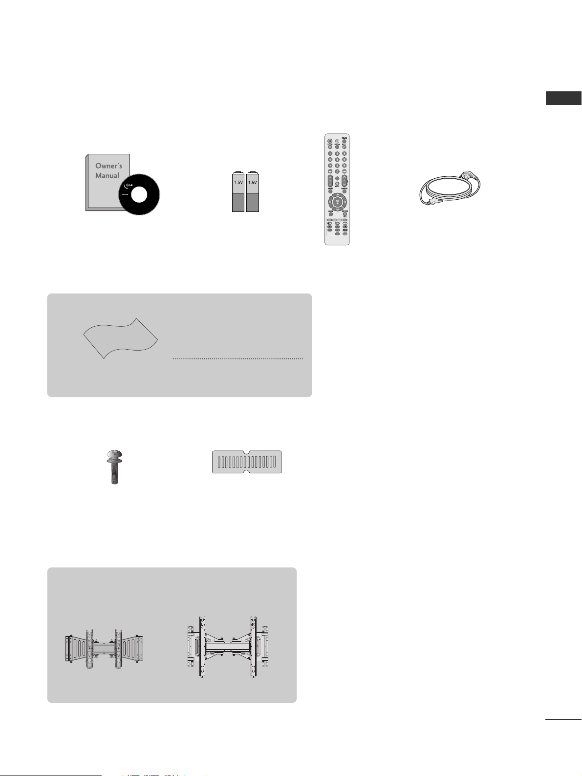
ACCESSORIES
ACCESSORIES
Ensure that the following accessories are included with your TV. If an accessory is missing, please contact the
dealer where you purchased the TV.
■
Here shown may differ from your TV.
Owner’s Manual
Batteries
Remote Control
Power Cord
Polishing Cloth
Polishing cloth for use on
the screen.
This item is not included for all models.
* Lightly wipe any stains or
fingerprints on the surface
of the set with the polishing
cloth.
Do not use excessive force. This
may cause scratching or discolouration.
Wall Mounting Bracket(Separate purchase)
AW-47LG30M
(47LH8***)
AW-55LH40M
(55LH8***)
POWERPOWER
TV/RADTV/RAD
ON/OFFON/OFF
RA RATIOTIO
AV MODEV MODE
MARKMARK
FAV
Screws for stand assembly
(Refer to p.10)
x 4
Protection cover
(Refer to p.12)
(Only 47LH8***)
CONTENTS
2
CONTENTS
ACCESSORIES
. . . . . . . . . . . . . . . . . . . . . . . . . . . . . . . . . . . . . . . . . . . .
1
PREPARATION
Front Panel Controls..................................................... 4
Back Panel Information ................................................ 6
Important Things to Know Before Installing the
Media Box........................................................................ 8
Installation Method for Media Box........................... 9
Stand Installation......................................................... 10
Back Cover for Wire Arrangement........................... 11
Careful installation advice ..................................... 12
Swivel Stand ..................................................................12
Not Using the Desk-type Stand ...............................12
Desktop Pedestal Installation ............................... 13
Wall Mount: Horizontal Installation........................ 13
Kensington Security System ..................................... 14
Antenna Connection................................................... 15
EXTERNAL EQUIPMENT SETUP
HD Receiver Setup...................................................... 16
DVD Setup..................................................................... 19
VCR Setup..................................................................... 21
Digital Audio Out Setup............................................ 23
Other A/V Source Setup........................................... 24
Usb Setup...................................................................... 25
PC Setup........................................................................ 26
- Screen Setup for PC Mode ...............................30
WATCHING TV / PROGRAMME CONTROL
Remote Control Key Functions ............................... 34
Turning on the TV ........................................................36
Programme Selection ................................................ 37
Volume Adjustment ................................................... 37
Quick Menu ................................................................. 38
On-Screen Menus Selection and Adjustment..... 39
Auto Programme Tuning............................................ 40
Manual Programme Tuning (In Digital Mode) ..... 41
Manual Programme Tuning (In Analogue Mode) .. . 42
Programme Edit ........................................................... 44
Software Update...........................................................46
Diagnostics ................................................................... 47
Selecting the Programme List.................................. 48
Favourite Programme Setup...................................... 49
Input List........................................................................ 50
Input Label..................................................................... 51
Simple manual .............................................................. 52
................................................................. 53
AV Mode........................................................................ 56
Initializing (Reset to original factory settings) .....57
TO USE A USB DEVICE
When connecting a USB device.............................. 58
Photo List ...................................................................... 59
Music List........................................................................63
Movie List .......................................................................66
DivX Registration Code..............................................70
Deactivation...................................................................71

CONTENTS
3
EPG (ELECTRONIC PROGRAMME
GUIDE) (IN DIGITAL MODE)
Switch on/off EPG ...................................................... 72
Select a Programme.................................................... 72
Button Function in NOW/NEXT Guide Mode ....... 72
Button Function in 8 Day Guide Mode..................73
Button Function in Date Change Mode................ 73
Button Function in Extended Description Box ..........7
4
Button Function in Remind Setting Mode
......................... 74
Button Function in Schedule List Mode................ 74
PICTURE CONTROL
Picture Size (Aspect Ratio) Control....................... 75
Picture Wizard................................................................77
Energy Saving.................................................................78
Preset Picture Settings
- Picture Mode-Preset............................................ 79
Manual Picture Adjustment
- Picture Mode-User option................................. 80
Picture Improvement Technology ........................... 81
Expert Picture Control............................................... 82
Picture Reset................................................................. 86
Demo Mode.................................................................. 87
Mode Setting .................................................................88
SOUND & LANGUAGE CONTROL
Auto Volume Leveler................................................... 89
Clear Voice II..................................................................90
Preset Sound Settings - Sound Mode................... 91
Sound Setting Adjustment -User Mode.................92
SRS TruSurround XT ...................................................92
Balance........................................................................... 93
TV Speakers On/ Off Setup......................................94
Selecting Digital Audio Out.......................................95
Audio Reset....................................................................96
Stereo Reception (In Analogue Mode Only) ........... 97
Speaker Sound Output Selection .......................... 98
Language Selection (In Digital Mode only)......... 99
TIME SETTING
Clock Setup................................................................ 100
Auto On/ Off Time Setting .................................... 101
Sleep Timer Setting .................................................. 102
PARENTAL CONTROL / RATINGS
Set Password & Lock System................................. 103
Block Programme...................................................... 104
Parental Control (In Digital Mode only)............. 105
External Input Blocking.............................................106
Key Lock ...................................................................... 107
TELETEXT
Switch on/off ............................................................. 108
SIMPLE Text................................................................ 108
TOP Text...................................................................... 108
FASTEXT...................................................................... 109
Special Teletext Functions ...................................... 109
APPENDIX
Troubleshooting ......................................................... 110
Maintenance ............................................................... 112
Product Specifications.............................................. 113
IR Codes....................................................................... 115
Open Source Software Notice ............................... 117
Open Source License ................................................ 118
4
PREPARATION
PREPARATION
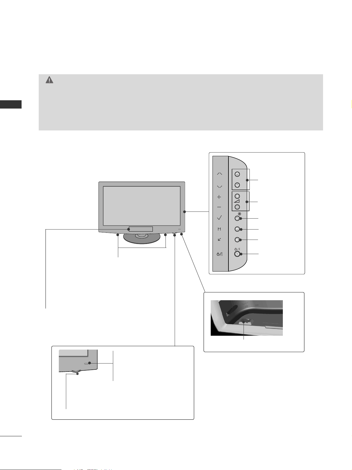
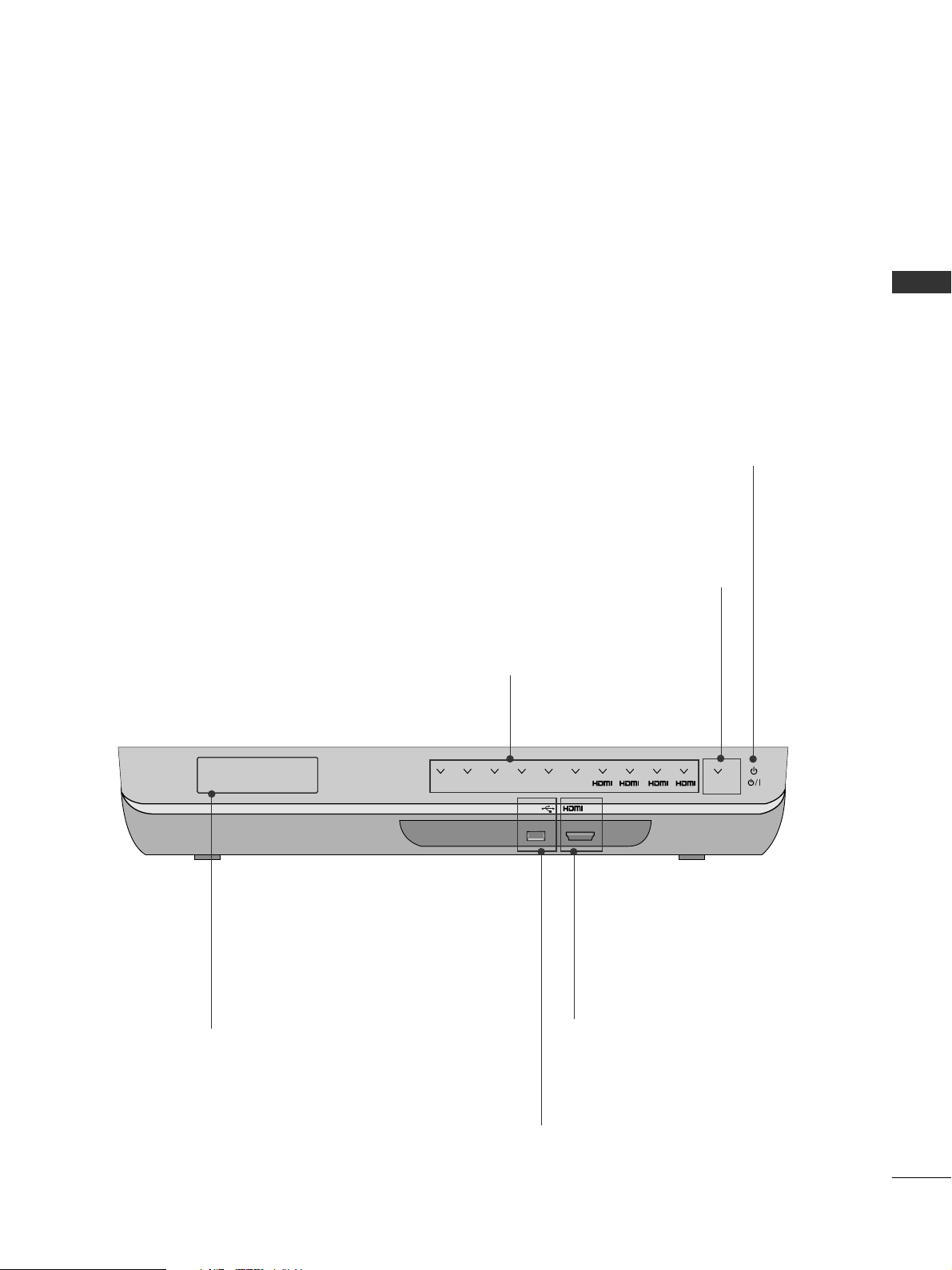
FRONT PANEL CONTROLS
■
Here shown may be somewhat different from your TV.
G
When the TV cannot be turned on with the remote control, press the main power button on the TV.
(When the power is turned off with the main power button on the TV, it will not be turned on with the
remote control).
G
Do not step on the glass stand or subject it to any impact.
It may break, causing possible injury from fragments of glass, or the TV may fall.
G
Do not drag the TV. The floor or the product may be damaged.
CAUTION
PROGRAMME
VOLUME
OK
MENU
INPUT
POWER
Main Power Switch
Remote Control Sensor
Intelligent Sensor
Adjusts picture according to the
surrounding conditions.
Power/Standby Indicator
•
Illuminates red in standby mode.
•
Illuminates white when the TV is switched on.
SPEAKER
Do not block this area. The wireless features will
not work properly if obstacles are in front of this
area.
Do not expose it to high humidity and temperature or dust.
P
OK
MENU
INPUT
5
PREPARATION
MEDIA BOX
■
Here shown may be somewhat different from your TV.
USB IN
IN 4
TV
AV1 AV2
COM1 COM21RGB WIRELESS
2 3 4
Input Source Indicator & INPUT touch button
Select the input source by touching.
POWER touch button
Turn the Media Box on or off by touching.
Even if you turn the Media Box off, it turns on again automatically if
the TV is switched on (when connected with the media box).
USB INPUT
Used for viewing photos, watching
movies and listening to MP3s.
HDMI IN
Digital Connection.
Supports HD video and Digital audio.
Doesn’t support 480i and 576i.
Wireless Connection Indicator
Blinks and then turns on when connecting wirelessly.
Do not place any obstacles between the
RF Receiver/Transmitter of the TV and
Media Box.
Do not expose it to high humidity and
temperature or dust.
* ID Label of Media Box is located at the bottom of Media Box.
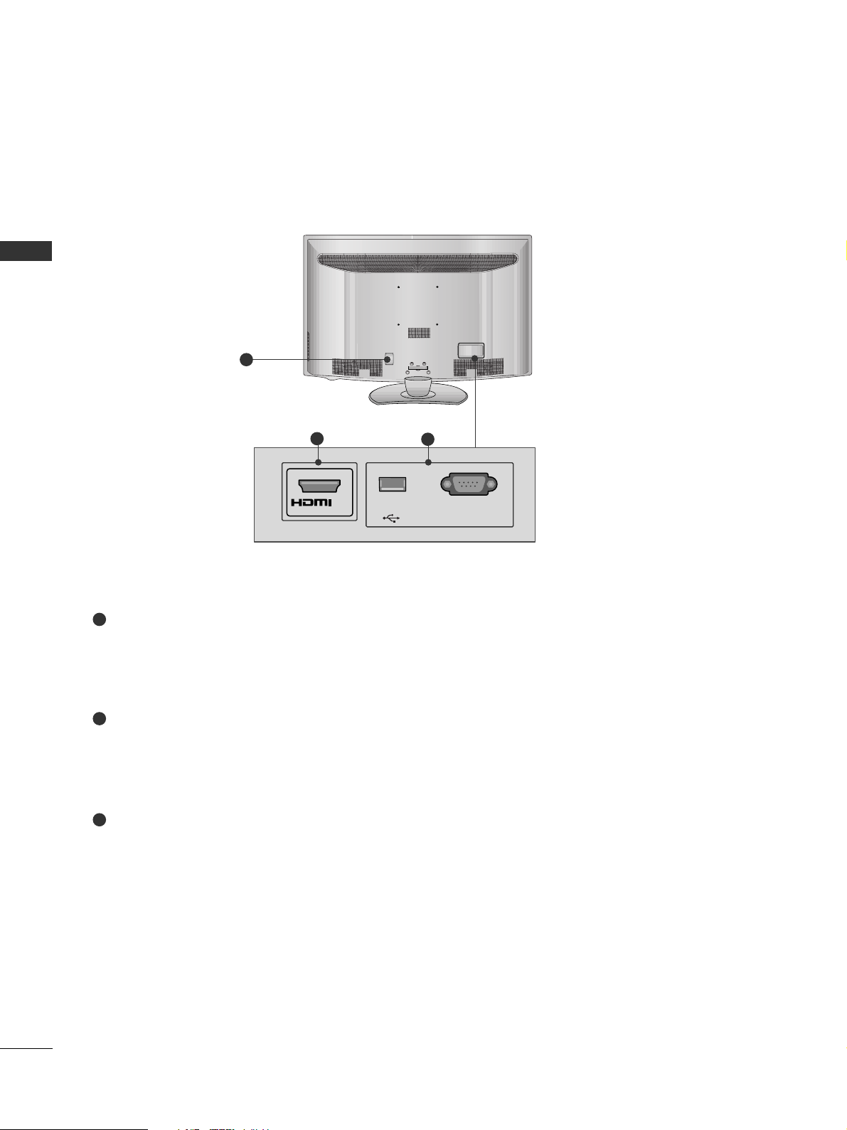
Power Cord Socket
This TV operates on an AC power. The voltage is indicated
on the Specifications page. Never attempt to operate the
TV on DC power.
HDMI IN
Digital Connection.
Supports HD video and Digital audio.
Doesn’t support 480i, 576i and SIMPLINK (HDMI-CEC).
USB SERVICE ONLY, SERVICE ONLY
Used for software updates.
6
PREPARATION
PREPARATION
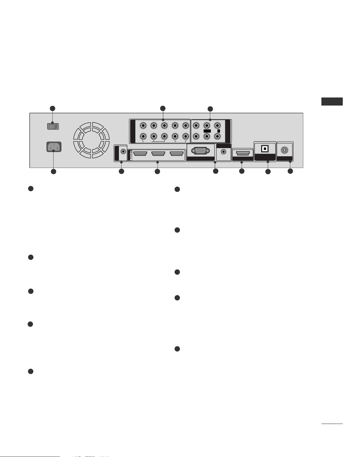
BACK PANEL INFORMATION
■
Here shown may be somewhat different from your TV.
1
2
3
1
3
2
USB
SERVICE ONLY
IN 5
SERVICE ONLY
7
PREPARATION
Main power switch
If you cannot turn the Media Box on with the
remote control, turn the power on using the Main
power switch and then switch the TV on with
POWER button on the remote control.
If you turned the Media Box off using the Main
power switch, you cannot turn it on with the
remote control.
Component Input
Connect a component video/audio device to
these jacks.
Audio/Video Input
Connect audio/video output from an external
device to these jacks.
Power Cord Socket
This Media Box operates on an AC power. The
voltage is indicated on the Specifications page.
Never attempt to operate the Media Box on DC
power.
RS-232C IN (SERVICE ONLY) PORT
Used for software updates.
HDMI/DVI IN Input
Connect a HDMI signal to HDMI IN. Or DVI
(VIDEO) signal to HDMI/DVI port with DVI to
HDMI cable.
RGB IN (PC) Input
Connect the output from a PC.
AUDIO IN (RGB/DVI) Input
Connect the audio from a PC or DTV.
SERVICE ONLY PORT
Used for software updates.
OPTICAL DIGITAL AUDIO OUT
Connect digital audio to various types of equipment.
Connect to a Digital Audio Component.
Use an Optical audio cable.
Antenna Input
Connect RF antenna to this jack.
1
2
3
4
5
6
7
8
9
10
1
2
1
2
COMPONENT IN
AV IN
LYPB PR R
VIDEO
AUDIO
L/MONO
R
213
/DVI IN
RGB IN (PC)
AUDIO IN
(RGB/DVI)
SERVICE ONLY
ANTENNA IN
RS-232C IN
(SERVICE ONLY)
OFFON
AC IN
VIDEO
AUDIO
OPTICAL DIGITAL
AUDIO OUT
MEDIA BOX
■
Here shown may be somewhat different from your TV.
1
3
2
9
10
6
7
4
5
8
8
PREPARATION
PREPARATION
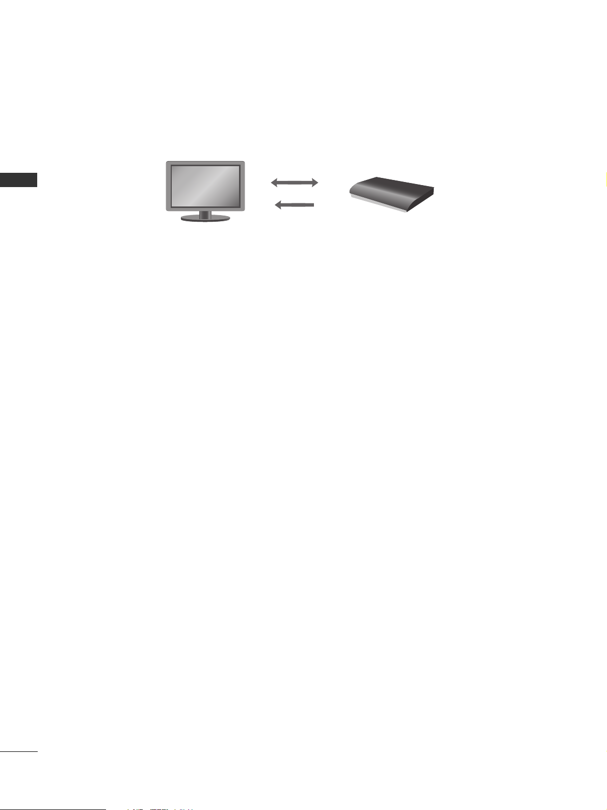
IMPORTANT THINGS TO KNOW BEFORE INSTALLING THE MEDIA BOX
■
The Media Box transmits 1080p HD videos wirelessly using the 60 GHz frequency.
■
It transmits uncompressed 1080p HD video to the TV up to 32.8 feet (10 m) in LOS (Line Of Sight).
■
It also features beam direction based on the 60 GHz frequency. If there are any obstacles in the way of transmission, the receiver uses an indoor wall or other reflective material and finds an alternative transmission path
immediately to avoid the obstacle and maintain the connection.
CAUTIONS IN INSTALLATION
■
The performance of radio-signal reception and video quality may differ depending on where the TV and Media Box
are located. To get better video quality, make sure to keep the distance between the TV and Media Box within LOS
(Line Of Sight) 32.8 feet (10 m) and have them face each other.
■
The RF Receiver/Transmitter is located on the front panels of the TV and Media Box. Do not place any obstacle
around the RF Receiver/Transmitter. And do not expose it to high humidity and temperature or dust.
■
The performance of radio-signal reception may be degraded if the Media Box is installed beside the TV. Press the
INFO button on the remote control to check the status of radio-signal reception and install the Media Box where
radio-signal reception is
SSttrroonn gg ssiiggnnaall
.
NOTE
■
This product is only for home use.
■
Do not use this product in medical institutions or near medical devices. It may cause some medical devices to
malfunction.
■
Video quality may be degraded or reception distance may be shortened depending on the surrounding circumstances.
■
If there are any obstacles between the TV and Media Box, the performance of radio-signal reception may be
degraded.
■
If there are any moving objects between the TV and Media Box, the screen may flicker briefly but will return to
normal immediately, and no problem will occur in operation.
■
If you install the Media Box out of the maximum range of reception/transmission, connection may fail or video
quality may be degraded.
■
If you install the Media Box to the left or right side of the TV, video quality may be degraded.
■
If you install the Media Box inside a metal cabinet, connection may fail.
■
If you install the Media Box on the middle of a table, connection may fail or video quality may be degraded. Install
the Media Box close to the edge of a table.
■
If there are two wireless TV sets or Media Boxes within LOS (Line Of Sight) 32.8 feet (10 m), they may interfere
with each other and wireless connection may fail.
■
If you use other 60GHz frequency bandwith wireless equipments with this product, it may affect the wireless connectivity by interference (To see RF specification, refer to P.114).
Data 1-40 Mbps
Video/Audio 3-4 Gbps
9
PREPARATION
INSTALLATION METHOD FOR MEDIA BOX
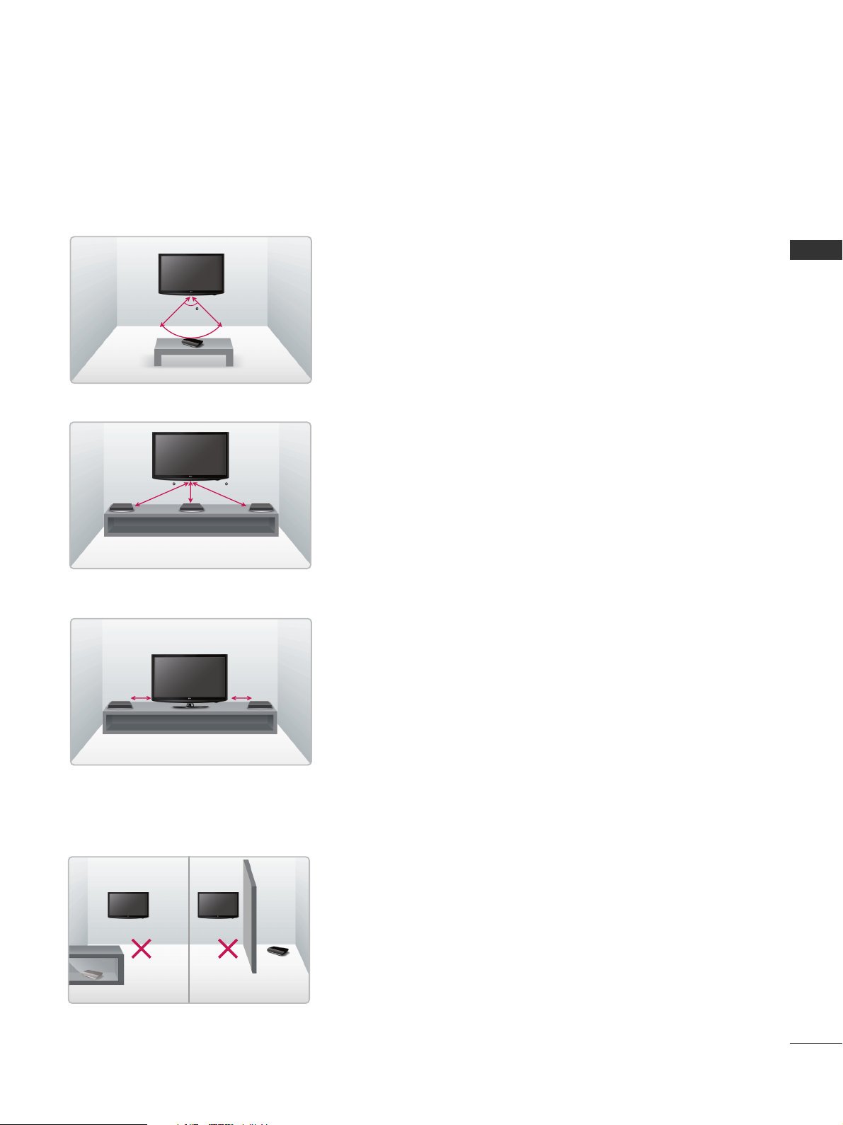
When the Media Box and TV are kept apart and facing each
other
■
This is a recommended installation type for good wireless connection.
Have the RF Receiver/Transmitter of the Media Box and TV face
each other. Keep the distance between them to within 32.8 feet
(10 m) and maintain the face angle of the TV within 100 degrees.
10m (32.8 feet)
10m
100
When installing the Media Box and TV on the same wall
Have the Media Box and TV face the front. Keep the distance
between them within 5.5 feet (1.7) m and maintain the face angle
of the TV within 60 degrees.
1.7m
1.7m1.7m (5.5 feet)
60 60
When installing the Media Box and TV side by side
Have the Media Box and TV face the front. Keep the distance
between them within 6.5 feet (2 m).
2m (6.5 feet) 2m
Precaution for installation environment
Do not place any obstacle around the RF Receiver/RF Transmitter.
If you install the Media Box inside a metal cabinet, connection
may fail.
If there are two wireless TV or Media Boxes within LOS (Line Of
Sight) 32.8 feet (10 m), they may interfere with each other and
wireless connection may fail.
Metal cabinet
Obstacle
10
PREPARATION
PREPARATION
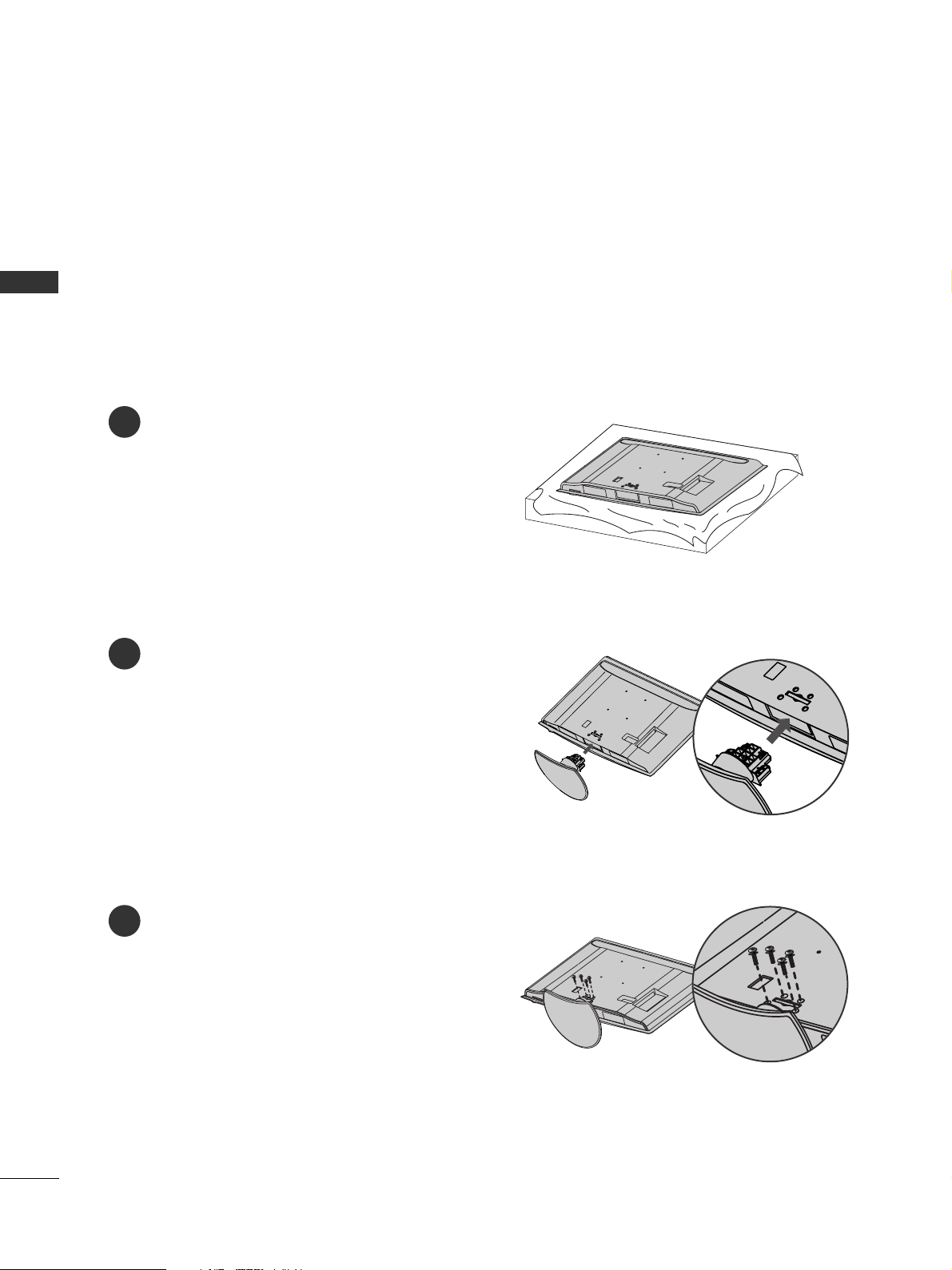
STAND INSTALLATIONS
(
Only 47LH8***)
1
2
3
Carefully place the TV screen side down on a cushioned
surface to protect the screen from damage.
Assemble the TV as shown.
Fix the 4 screws securely using the holes in the
back of the TV.
■
Image shown may differ from your TV
When assembling the desk type stand, check whether the screws are fully tightened. (If not tightened fully, the
product can tilt forward after the product installation.) If you tighten the bolt with excessive force, the bolt can
deviate from abrasion of the tightening part of the bolt.
11
PREPARATION
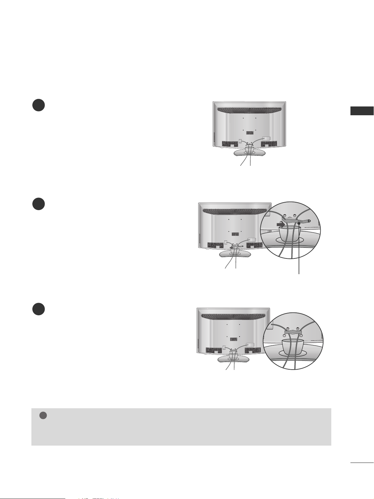
BACK COVER FOR WIRE ARRANGEMENT
■
Here shown may be somewhat different from your TV.
CABLE MANAGEMENT CLIP
1
2
3
Connect the cables as necessary.
To connect additional equipment, see the
External Equipment Setup section of the manual.
Open the
CC AABB LLEE MMAA NNAAGG EEMMEENNTT CCLLIIPP
as
shown and manage the cables.
Fit the
CC AABB LLEE MMAA NNAAGG EEMMEENNTT CCLLIIPP
as
shown.
NOTE
!
GG
Do not use the CABLE MANAGEMENT CLIP to lift the TV.
- If the TV is dropped, you may be injured or the TV may be damaged.
12
PREPARATION
PREPARATION
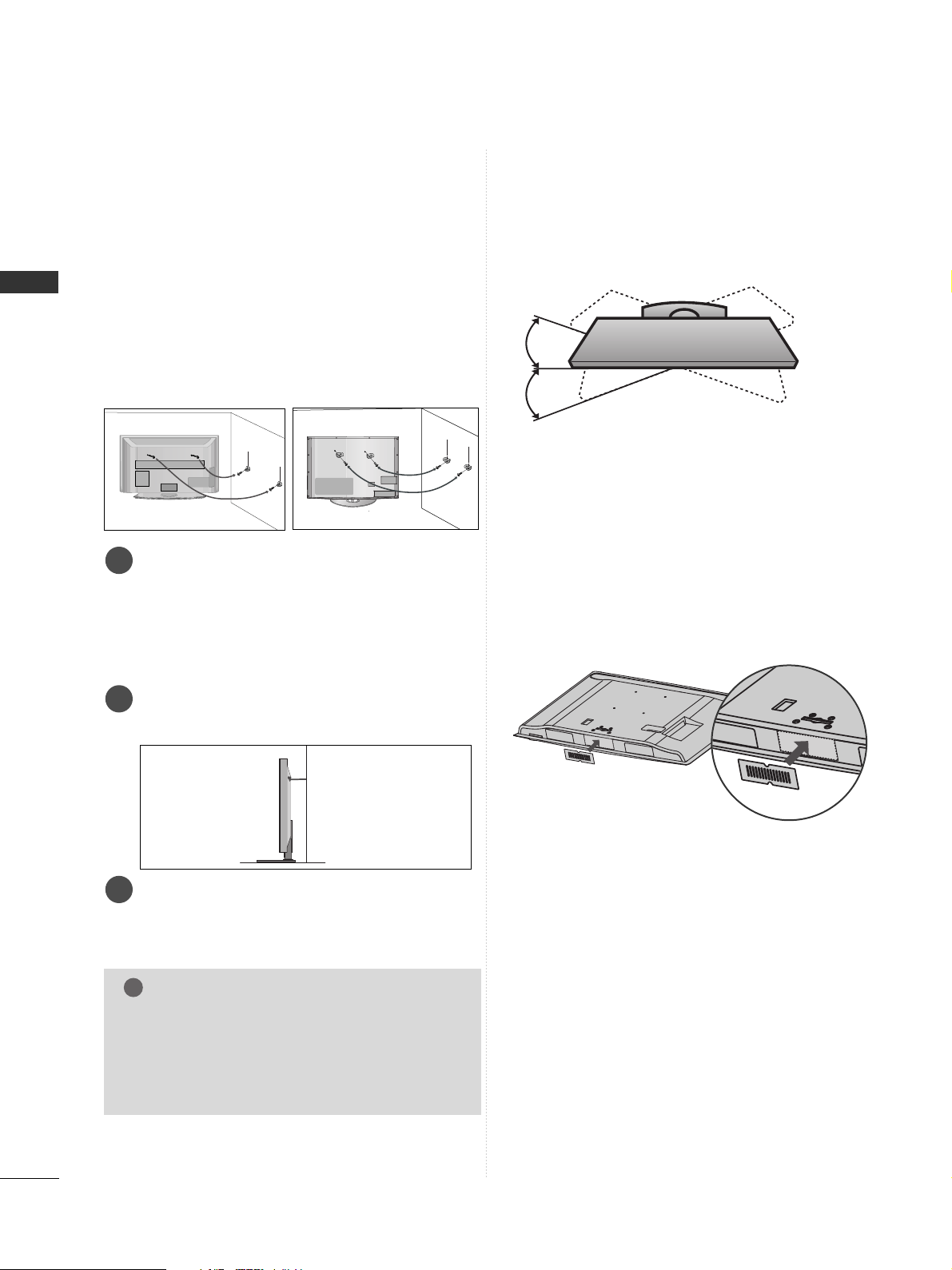
■
Here shown may be somewhat different from your TV.
When installing the wall-mounted unit, use the protection cover.
After removing the protection paper from the protection cover, adhere it to the TV as shown.
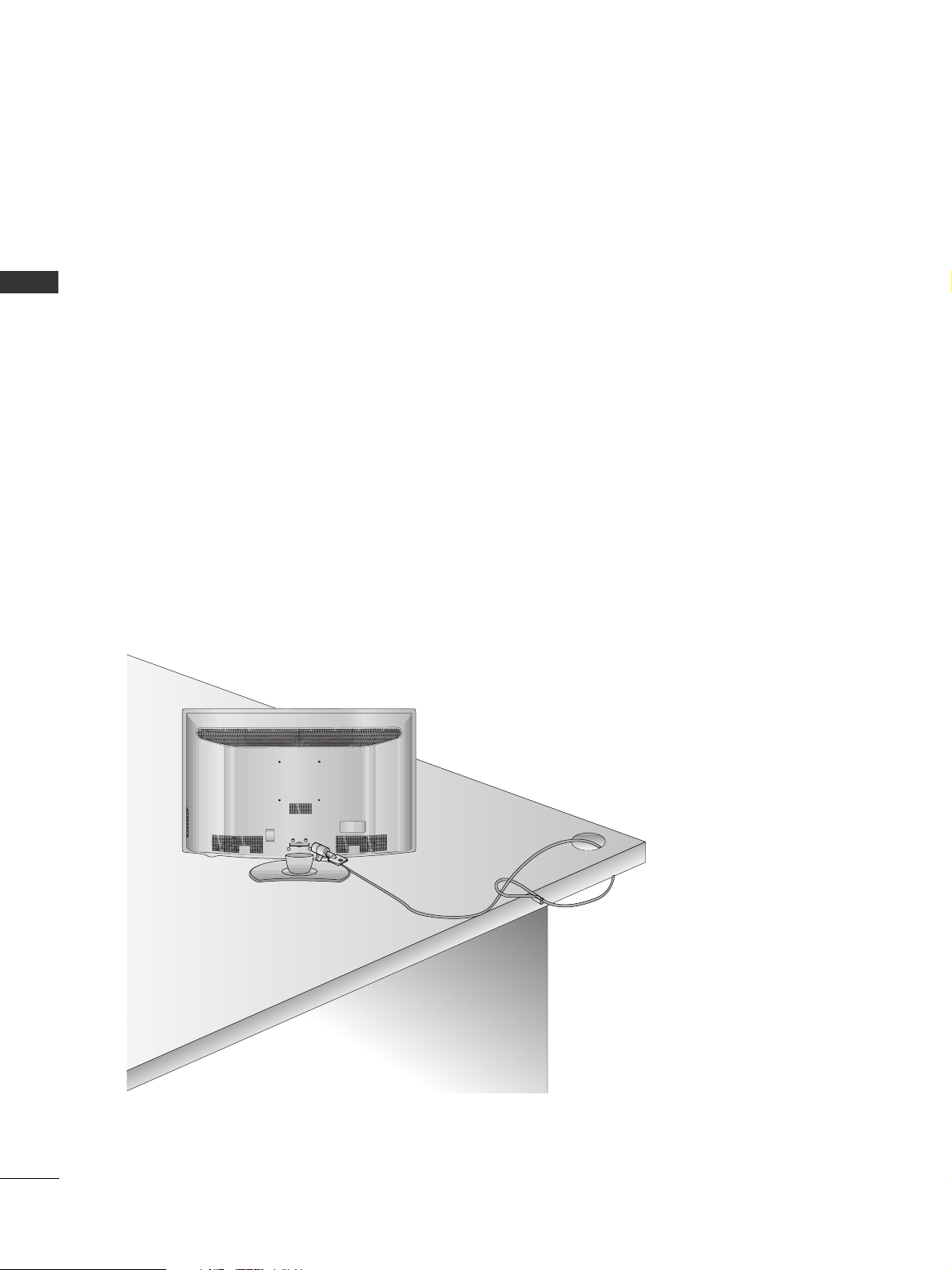
NOT USING THE DESK-TYPE STAND
CAREFUL INSTALLATION ADVICE
A
You should purchase necessary components to fix the TV
safety and secure to the wall on the market.
A
Position the TV close to the wall to avoid the possibility
of it falling when pushed.
A
The instructions shown below are a safer way to set up
the TV, by fixing it to the wall, avoiding the possibility of
it falling forwards if pulled. This will prevent the TV from
falling forward and causing injury. This will also prevent
the TV from damage. Ensure that children do not climb
or hang from the TV.
NOTE
!
G
When moving the TV undo the cords first.
G
Use a platform or cabinet strong and large enough
to support the size and weight of the TV.
G
To use the TV safely make sure that the height of the
bracket on the wall and on the TV is the same.
3
1
2
Use the eye-bolts or TV brackets/bolts to fix the
product to the wall as shown in the picture.
(If your TV has bolts in the eyebolts, loosen then
bolts.)
* Insert the eye-bolts or TV brackets/bolts and tight-
en them securely in the upper holes.
Secure the wall brackets with the bolts on the wall.
Match the height of the bracket that is mounted on
the wall.
3
Use a sturdy rope to tie the product for alignmen. It
is safer to tie the rope so it becomes horizontal
between the wall and the product.
2
1
2
1
SWIVEL STAND
After installing the TV, you can adjust the TV set
manually to the left or right direction by 20 degrees
to suit your viewing position.
13
PREPARATION
4 inches
4 inches
4 inches
4 inches
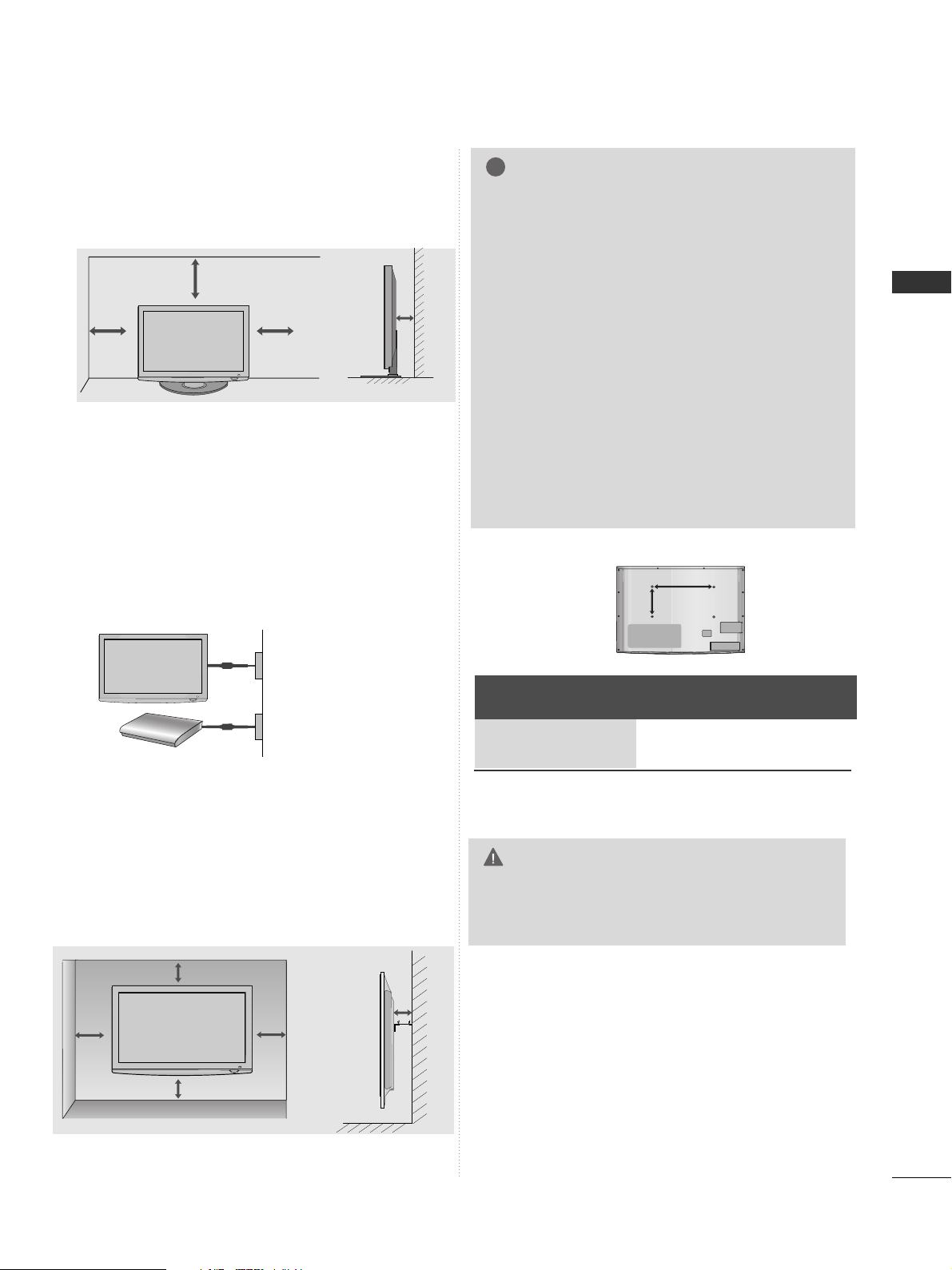
DESKTOP PEDESTAL INSTALLATION
For adequate ventilation allow a clearance of 4”
(10cm) all around the TV.
A
The TV can be installed in various ways such as on a
wall, or on a desktop etc.
A
The TV is designed to be mounted horizontally.
Power Supply
Circuit breaker
EARTHING
Ensure that you connect the earth wire to prevent
possible electric shock. If grounding methods are not
possible, have a qualified electrician install a separate
circuit breaker.
Do not try to earth the TV by connecting it to telephone wires, lightening rods or gas pipes.
WALL MOUNT: HORIZONTAL INSTALLATION
A
We recommend the use of a LG Brand wall mounting
bracket when mounting the TV to a wall.
A
We recommend that you purchase a wall mounting
bracket which supports VESA standard.
A
LG recommends that wall mounting be performed by a
qualified professional installer.
NOTE
!
G Should Install wall mount on a solid wall perpendicular to
the floor.
G Should use a special wall mount, if you want to install it to
ceiling or slanted wall.
G The surface that wall mount is to be mounted on should
be of sufficient strength to support the weight of TV set;
e.g. concrete, natural rock, brick and hollow block.
G Installing screw type and length depends on the wall
mount used. Further information, refer to the instructions
included with the mount.
G LG is not liable for any accidents or damage to property or
TV due to incorrect installation:
- Where a non-compliant VESA wall mount is used.
- Incorrect fastening of screws to surface which may cause
TV to fall and cause personal injury.
- Not following the recommended Installation method.
4 inches
4 inches
4 inches
4 inches
4 inches
AA
BB
Model
VESA
(A *B)
Standard
Screw
Quantity
47LH8***
55LH8***
200 * 200
400 * 400M6M6
4
4
GG
Do not install your wall mount kit while your TV is
turned on. It may result in personal injury due to
electric shock.
CAUTION
14
PREPARATION
PREPARATION
KENSINGTON SECURITY SYSTEM
■
This feature is not available for all models.
■
Here shown may be somewhat different from your TV.
The TV is equipped with a Kensington Security System connector on the back panel. Connect the Kensington
Security System cable as shown below.
For the detailed installation and use of the Kensington Security System, refer to the user’s guide provided with
the Kensington Security System.
For further information, contact http://www.kensington.com, the internet homepage of the Kensington
company. Kensington sells security systems for expensive electronic equipment such as notebook PCs and LCD
projectors.
NOTE
- The Kensington Security System is an optional accessory.
NOTES
a. If the TV feels cold to the touch, there may be a small “flicker” when when it is turned on.
This is normal, there is nothing wrong with TV.
b. Some minute dot defects may be visible on the screen, appearing as tiny red, green, or blue spots. However,
they have no adverse effect on the monitor's performance.
c. Avoid touching the LCD screen or holding your finger(s)
against it for long periods of time.
Doing so may produce some temporary distortion effects on the screen.
ANTENNA IN
15
PREPARATION
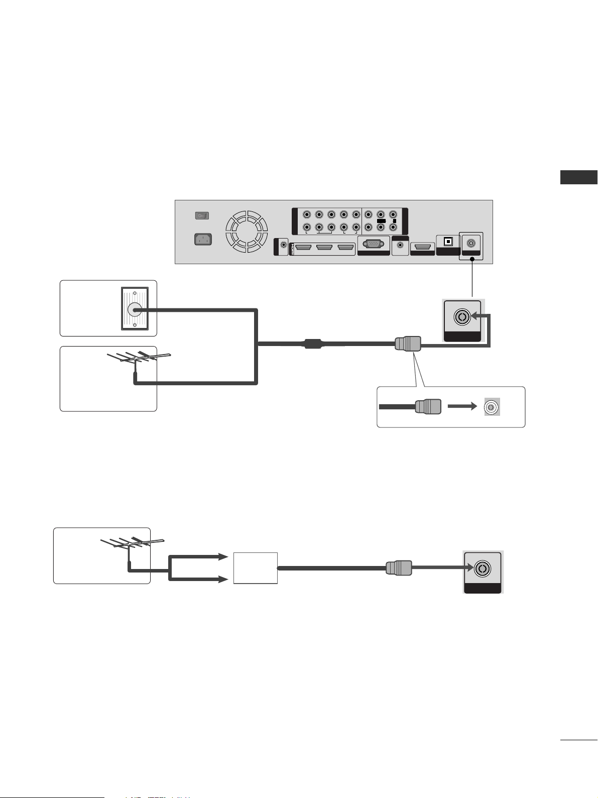
ANTENNA IN
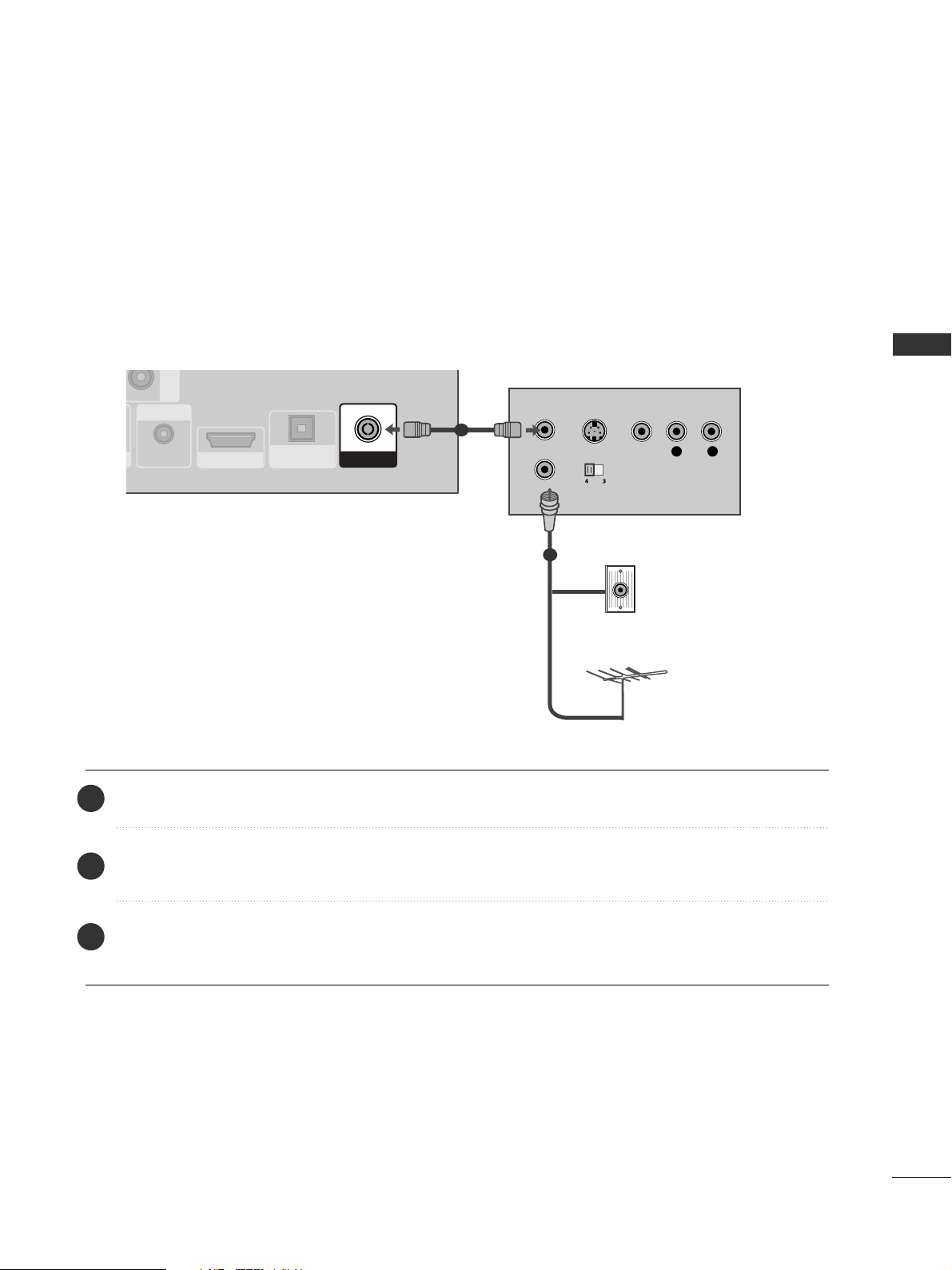
ANTENNA CONNECTION
■
For optimum picture quality, adjust antenna direction.
■
An antenna cable and converter are not supplied.
■
To prevent damage do not connect to the mains outlet until all connections are made between the devices.
Multi-family Dwellings/Apartments
(Connect to wall antenna socket)
Single-family Dwellings /Houses
(Connect to wall jack for outdoor antenna)
Outdoor
Antenna
(VHF, UHF)
Wall
Antenna
Socket
RF Coaxial Wire (75 ohm)
Antenna
UHF
Signal
Amplifier
VHF
■
In poor signal areas, to achieve better picture quality it may be necessary to install a signal amplifier to the
antenna as shown above.
■
If signal needs to be split for two TVs, use an antenna signal splitter for connection.
1
2
1
2
COMPONENT IN
AV IN
LYPB PR R
VIDEO
AUDIO
L/MONO
R
213
/DVI IN
RGB IN (PC)
AUDIO IN
(RGB/DVI)
SERVICE ONLY
ANTENNA IN
RS-232C IN
(SERVICE ONLY)
OFFON
AC IN
VIDEO
AUDIO
OPTICAL DIGITAL
AUDIO OUT
16
EXTERNAL EQUIPMENT SETUP
EXTERNAL EQUIPMENT SETUP
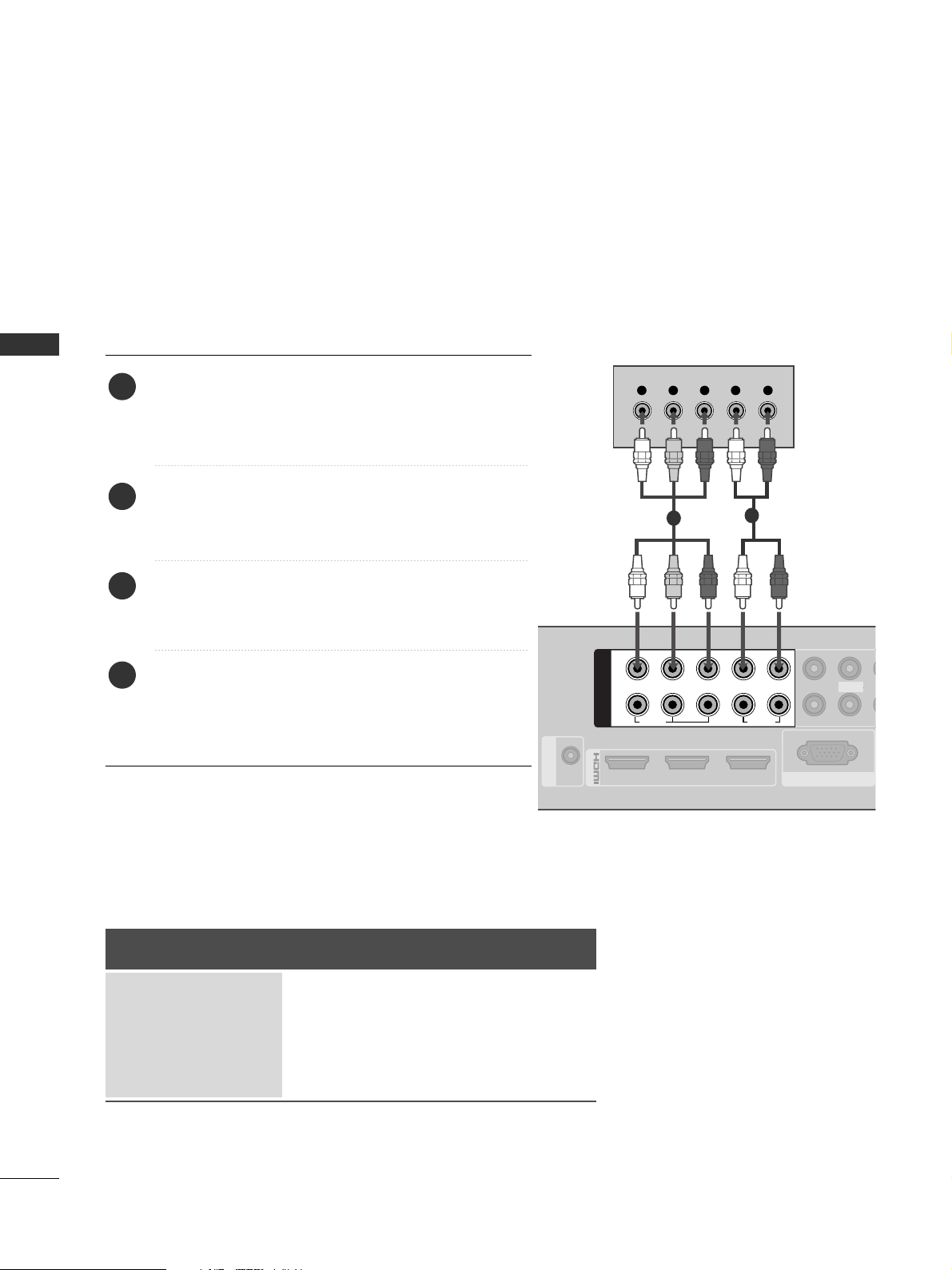
HD RECEIVER SETUP
■
To avoid damaging any equipment, never plug in any power cords until you have finished connecting all equipment.
■
Here shown may differ from your TV.
Connecting with a component cable
213
/DVI IN
RGB IN (PC)
RS-232C IN
(SERVICE ONLY)
1
2
COMPONENT IN
LYPB PR R
VIDEO
AUDIO
Y L RPB PR
VIDEO
AUD
L/MONO
1
2
Signal
480i/576i
480p/576p
720p/1080i
10 8 0 p
Component
O
O
O
O
(50Hz/60Hz)
HDMI
X
O
O
O
(24Hz/30Hz/50Hz/60Hz)
■
This Media Box can receive Digital RF/Cable signals without an external digital set-top box. However, if you do
receive Digital signals from a digital set-top box or other digital external device, refer to the diagram as shown
below.
Connect the video outputs (Y, PB, PR
)
of the digital set
top box to the
CC OOMMPPOO NN EENNTT IINN VV IIDD EEOO
jacks on
the Media Box. Match the jack colours (Y = green, P
B
= blue, and PR = red).
Connect the audio output of the digital set-top box to
the
CC OOMMPPOO NN EENNTT IINN AAUUDDIIOO
jacks on the Media
Box.
Turn on the digital set-top box.
(
Refer to the owner’s manual for the digital set-top
box.
)
Select
CC oo mm ppoonneenn tt11
input source using the
IINN PPUU TT
button on the remote control.
If connected to
CC OOMMPPOO NN EENNTT II NN 22
, select
CC oo mm ppoonnee nntt 22
input source.
2
3
4
1
GG
HDMI Audio Supported format : Dolby Digital, PCM
17
EXTERNAL EQUIPMENT SETUP
1
2
COMPONENT IN
LYPB PR R
VID
RG
VIDEO
AUDIO
213
/DVI IN
HDMI OUTPUT
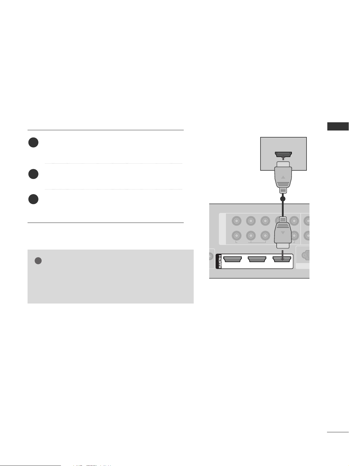
Connecting a set-top box with an HDMI cable
1
Connect the digital set-top box to
HHDDMMII//DD VVII IINN 11
,
HHDDMMII//DD VVII IINN 22,HHDDMMII//DD VVII IINN 33
or
HHDDMMII II NN 44
jack on the Media Box or
HHDDMMII IINN 55
on the TV.
Turn on the digital set-top box.
(
Refer to the owner’s manual for the digital set-top box.
)
Select
HH DD MMII11, HH DD MMII22, HH DD MMII33, HH DD MMII 44
or
HH DD MMII55
input source using the
IINN PPUU TT
button on the remote
control.
2
3
1
GG
Check that your HDMI cable is version 1.3 or higher.
If the HDMI cables don’t support HDMI version 1.3, flickering or no screen display can result. Please use the latest
cables that support at least HDMI version 1.3.
NOTE
!
18
EXTERNAL EQUIPMENT SETUP
EXTERNAL EQUIPMENT SETUP
EXTERNAL EQUIPMENT SETUP
1
2
1
2
COMPONENT IN
AV IN
LYPB PR R
VIDEO
AUDIO
RGB IN (PC)
VIDEO
AUDIO
L/MONO
R
2 13
/DVI IN
AUDIO IN
(RGB/DVI)
L R
DVI OUTPUT
AUDIO
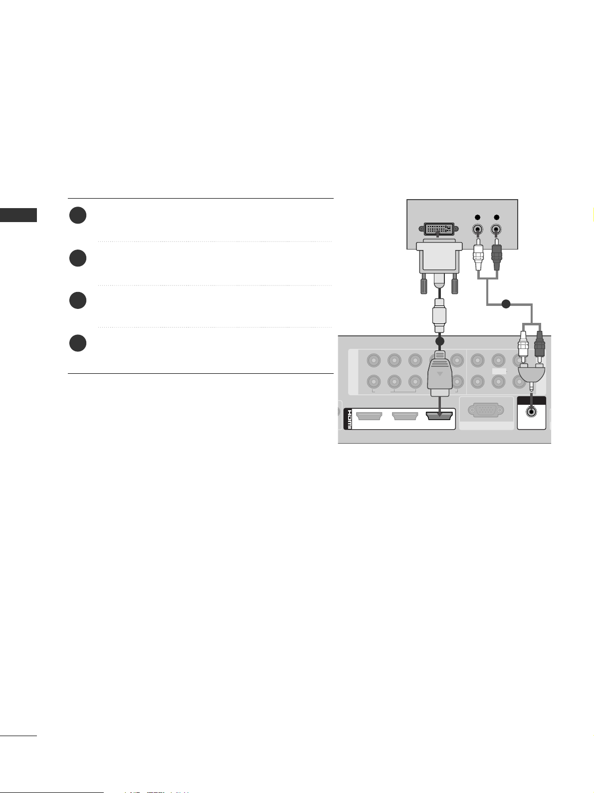
Connecting with an HDMI to DVI cable
1
2
Connect the digital set-top box to
HHDDMMII //DDVVII IINN 11
jack on the Media Box.
Connect the audio output of the digital set-top box to
the
AAUU DDII OO IINN ((RRGGBB//DD VVII ))
jack on the Media Box.
Turn on the digital set-top box. (Refer to the owner’s
manual for the digital set-top box.
)
Select
HH DD MMII 11
input source using the
IINN PPUU TT
button
on the remote control.
2
3
4
1
19
EXTERNAL EQUIPMENT SETUP
DVD SETUP
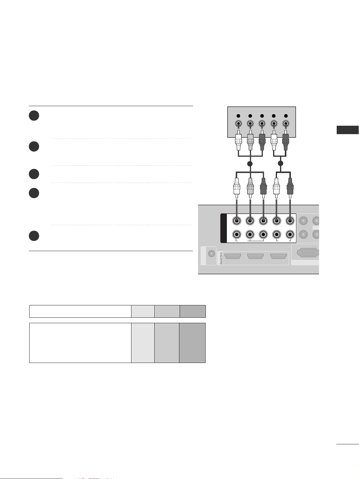
Connecting with a component cable
213
/DVI IN
RGB IN (PC)
RS-232C IN
(SERVICE ONLY)
1
2
COMPONENT IN
LYPB PR R
VIDEO
AUDIO
Y L RPB PR
VIDEO
L/MON
Component Input ports
To achieve better picture quality, connect a DVD player to
the component input ports as shown below.
Component ports on the Media Box
YPB PR
Video output ports
on DVD player
Y
Y
Y
Y
P
B
B-Y
Cb
Pb
P
R
R-Y
Cr
Pr
1
2
Connect the video outputs (Y, PB, PR
)
of the DVD to
the
CC OOMMPPOO NN EENNTT IINN VV IIDD EEOO
jacks on the Media
Box.
Connect the audio outputs of the DVD to the
CC OOMMPPOO NN EENNTT IINN AAUUDDIIOO
jacks on the Media Box.
Turn on the DVD player, insert a DVD.
Select
CC oo mm ppoonnee nntt 11
input source using the
IINN PPUU TT
button on the remote control.
If connected to
CC OOMMPPOO NN EENNTT II NN 22
, select
CC oo mm ppoonnee nntt 22
input source.
Refer to the DVD player's manual for operating
instructions.
2
3
4
5
1
20
EXTERNAL EQUIPMENT SETUP
EXTERNAL EQUIPMENT SETUP
O
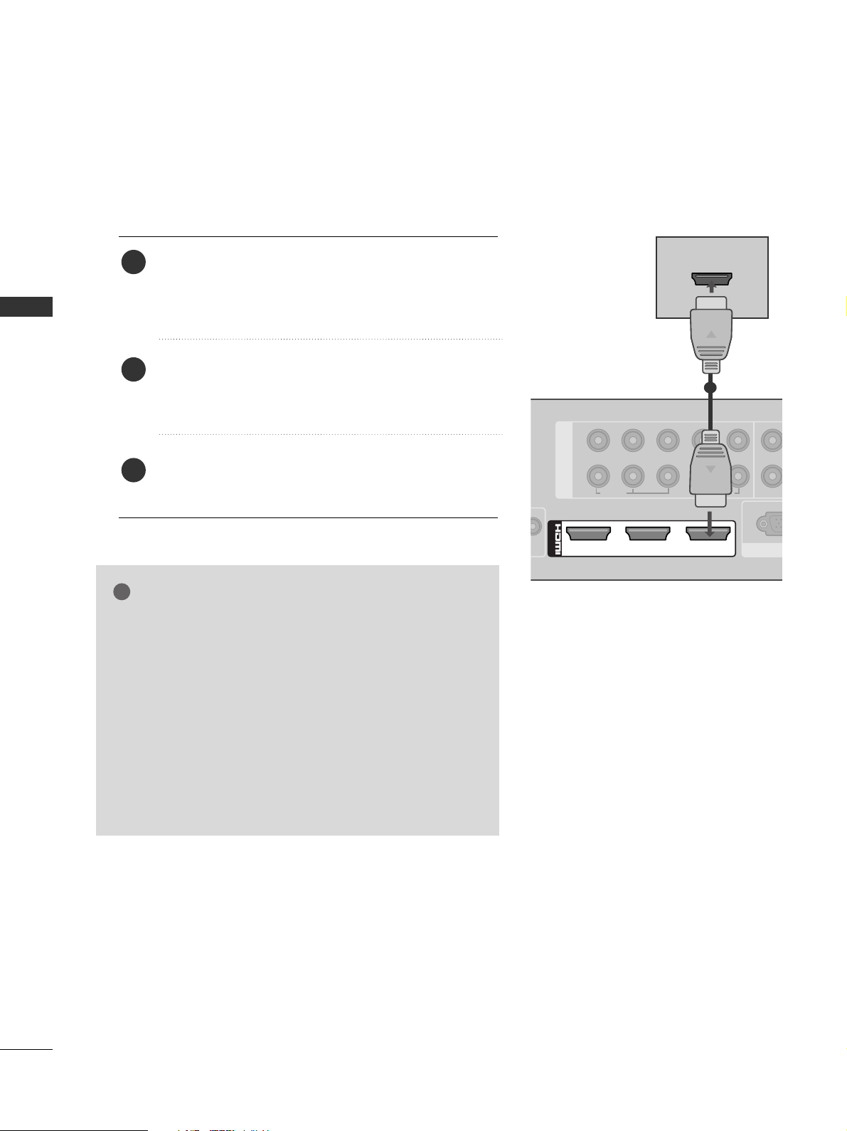
Connecting the HDMI cable
Connect the HDMI output of the DVD to the
HHDDMMII//DD VVII IINN 11,HHDDMMII//DD VVII IINN 22,HHDDMMII//DD VVII IINN
33
, or
HHDDMMII IINN 44
jack on the Media Box or
HHDDMMII II NN
55
on the TV.
Select
HH DD MMII11, HH DD MMII22, HH DD MMII33, HH DD MMII 44
or
HH DD MMII55
input source using the
IINN PPUU TT
button on the remote
control.
Refer to the DVD player's manual for operating
instructions.
2
3
1
1
GG
The Media Box or TV can receive video and audio signals
simultaneously when using an HDMI cable.
GG
If the DVD does not support Auto HDMI, you must set the
output resolution appropriately.
GG
The TV set can process audio format of PCM or Dolby
Digital, when connect the external equipment using an HDMI
cable.
GG
Check that your HDMI cable is version 1.3 or higher.
If the HDMI cables don’t support HDMI version 1.3, flickering or no screen display can result. Please use the latest
cables that support at least HDMI version 1.3.
NOTE
!
COMPONENT IN
1
2
VIDEO
/DVI IN
213
HDMI OUTPUT
LYPB PR R
AUDIO
VIDE
RGB
21
EXTERNAL EQUIPMENT SETUP
VCR SETUP
■
To avoid picture noise (interference), allow adequate distance between the VCR and Media Box.
N
AUDIO IN
(RGB/DVI)
SERVICE ONLY
OPTICAL DIGITAL
AUDIO OUT
ANTENNA IN
L R
S-VIDEO VIDEO
OUTPUT
SWITCH
ANT IN
ANT OUT
AUDIO
Wall Jack
Antenna
1
2
Connecting with a RF Cable
Connect the
AANN TT OO UUTT
socket of the VCR to the
AANN TTEENN NN AA II NN
socket on the Media Box.
Connect the antenna cable to the
AANN TT II NN
socket of the VCR.
Press the
PPLLAAYY
button on the VCR and match the appropriate channel between the Media Box and
VCR for viewing.
2
3
1
22
EXTERNAL EQUIPMENT SETUP
EXTERNAL EQUIPMENT SETUP
EXTERNAL EQUIPMENT SETUP
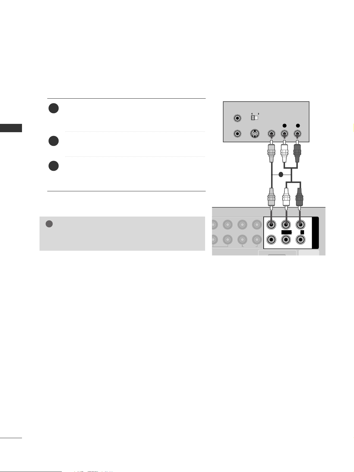
Connecting with a RCA cable
Connect the
AAUUDDII OO/VVIIDDEE OO
jacks between Media
Box and VCR. Match the jack colours (Video = yellow,
Audio Left = white, and Audio Right = red)
Insert a video tape into the VCR and press PLAY on
the VCR. (Refer to the VCR owner’s manual.
)
Select
AA VV 11
input source using the
IINN PPUU TT
button on
the remote control.
If connected to
AAVV22
input, select
AAVV22
input source.
1
2
3
GG
If you have a mono VCR, connect the audio cable from the
VCR to the
AAUUDDIIOO LL//MMOO NN OO
jack of the Media Box.
NOTE
!
AUDIO IN
AV IN
VIDEO
AUDIO
L/MONO
R
L R
S-VIDEO VIDEO
AUDIO
OUTPUT
SWITCH
ANT IN
ANT OUT
1
2
LPB PR R
AUDIO
1
23
EXTERNAL EQUIPMENT SETUP
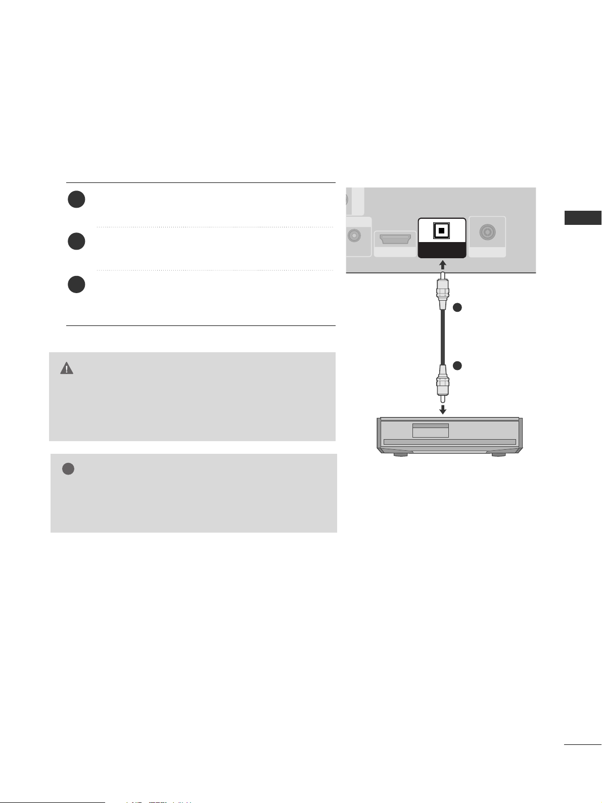
GG
Do not look into the optical output port. Looking at the
laser beam may damage your vision.
GG
Audio with ACP (Audio Copy Protection) function may
block digital audio output.
CAUTION
V IN
UDIO IN
SERVICE ONLY
ANTENNA IN
OPTICAL DIGITAL
AUDIO OUT
Connect one end of an optical cable to the Media Box
port of
OOPPTT IICCAALL DDIIGGIITTAALL AAUUDDIIOO OOUUTT
.
Connect the other end of the optical cable to the digital audio (Optical)input on the audio equipment.
Set the “TV Speaker option - Off ” in the AUDIO
menu.(
G
pp..9944
) Refer to the external audio equipment
instruction manual for operation.
2
3
1
1
2
DIGITAL AUDIO OUT SETUP
Sending the TV’s audio signal to external audio equipment via the Digital Audio Output (Optical) port.
If you want to enjoy digital broadcasting through 5.1-channel speakers, connect the OPTICAL DIGITAL
AUDIO OUT terminal on the back of Media Box to a Home Theater (or amp).
GG
When connecting with external audio equipments, such as
amplifiers or speakers, please turn the TV speakers off.
GG
HDMI5 input source cannot be used for AUDIO OUT.
NOTE
!
24
EXTERNAL EQUIPMENT SETUP
EXTERNAL EQUIPMENT SETUP
EXTERNAL EQUIPMENT SETUP
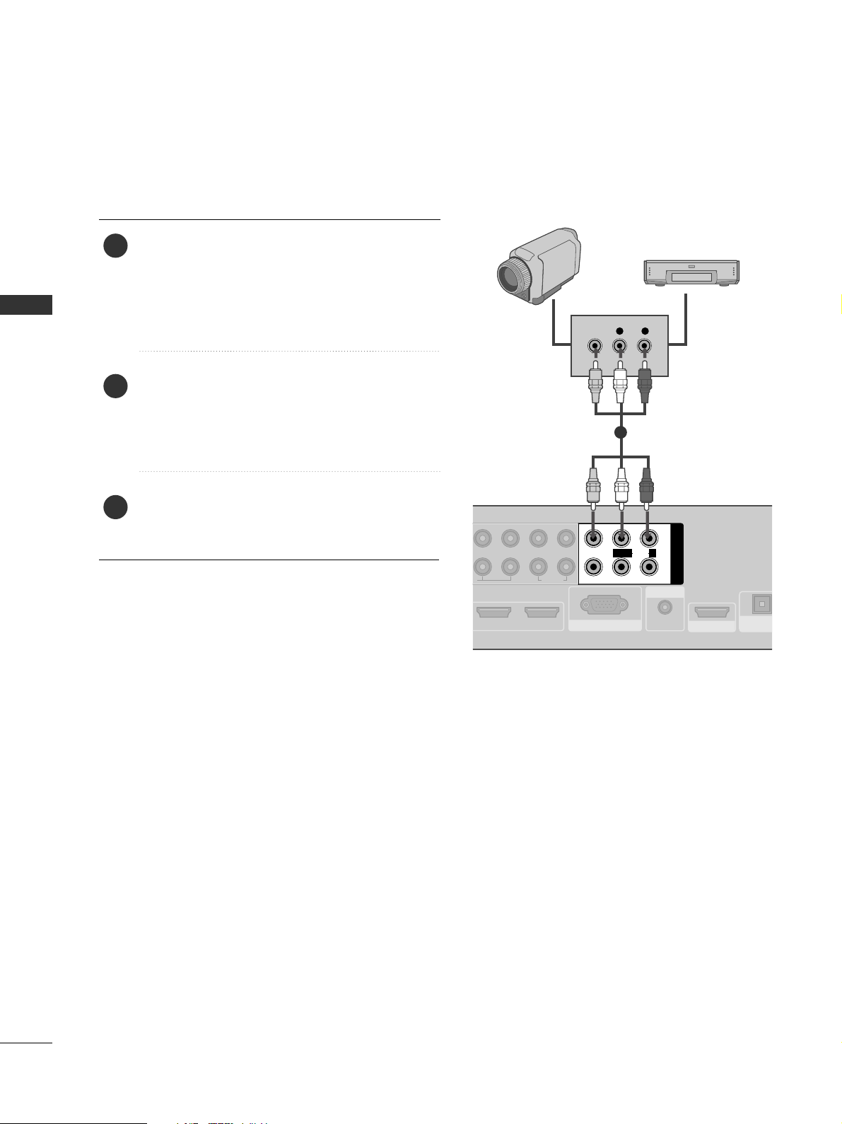
OTHER A/V SOURCE SETUP
Connect the
AAUUDDIIOO/VVIIDDEEOO
jacks between
Media Box and external equipment. Match the
jack colours
.
(
Video = yellow, Audio Left = white, and Audio
Right = red
)
Select
AA VV 11
input source with using the
IINN PPUU TT
button on the remote control.
If connected to
AAVV22
input, select
AAVV22
input
source.
Operate the corresponding external equipment.
Refer to external equipment operating guide.
1
2
3
21
RGB IN (PC)
AUDIO IN
(RGB/DVI)
AV IN
VIDEO
AUDIO
L/MONO
R
L R
VIDEO
1
2
LPB PR R
AUDIO
SERVICE ONLY
OPTICAL DIG
AUDIO OU
Camcorder
Video Game Set
1
25
EXTERNAL EQUIPMENT SETUP
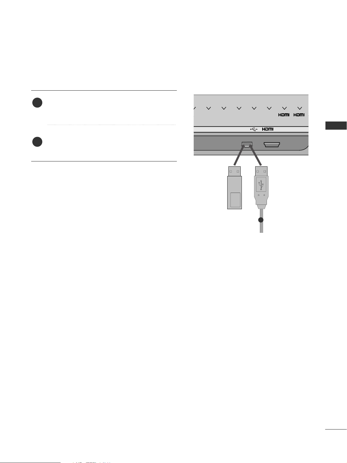
USB SETUP
USB IN
IN 4
Memory Key
AV1 AV2
COM1 COM21RGB
2
Connect the USB device to the
UUSSBB IINN
jacks on
the Media Box.
After connecting the
UUSSBB IINN
jacks, you use the
UU SS BB
function. (
GG
pp..5588
)
2
1
1
26
EXTERNAL EQUIPMENT SETUP
EXTERNAL EQUIPMENT SETUP
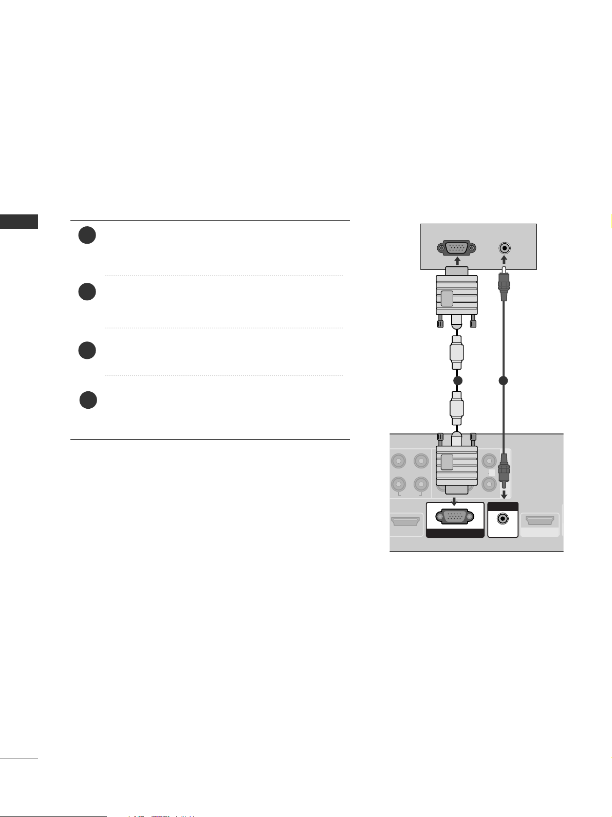
PC SETUP
This TV provides Plug and Play capability, meaning that the PC adjusts automatically to the Media Box's settings.
Connecting with a D-sub 15 pin cable
AV IN
L R
VIDEO
AUDIO
1
SERVICE ONLY
AUDIO
L/MONO
R
O
RGB IN (PC)
AUDIO IN
(RGB/DVI)
RGB OUTPUT
AUDIO
1 2
4
Connect the RGB output of the PC to the
RRGGBB IINN
((PP CC))
jack on the Media Box.
Connect the PC audio output to the
AAUU DDIIOO IINN
((RRGGBB// DDVV II))
jack on the Media Box.
Turn on the PC and the Media Box.
Select
RR GGBB
input source using the INPUT button on
the remote control.
2
3
1
27
EXTERNAL EQUIPMENT SETUP
1
2
COMPONENT IN
AV IN
LYPB PR R
VIDEO
AUDIO
RGB IN (PC)
S
VIDEO
AUDIO
L/MONO
R
1
/DVI IN
AUDIO IN
(RGB/DVI)
23
DVI-PC OUTPUT
AUDIO
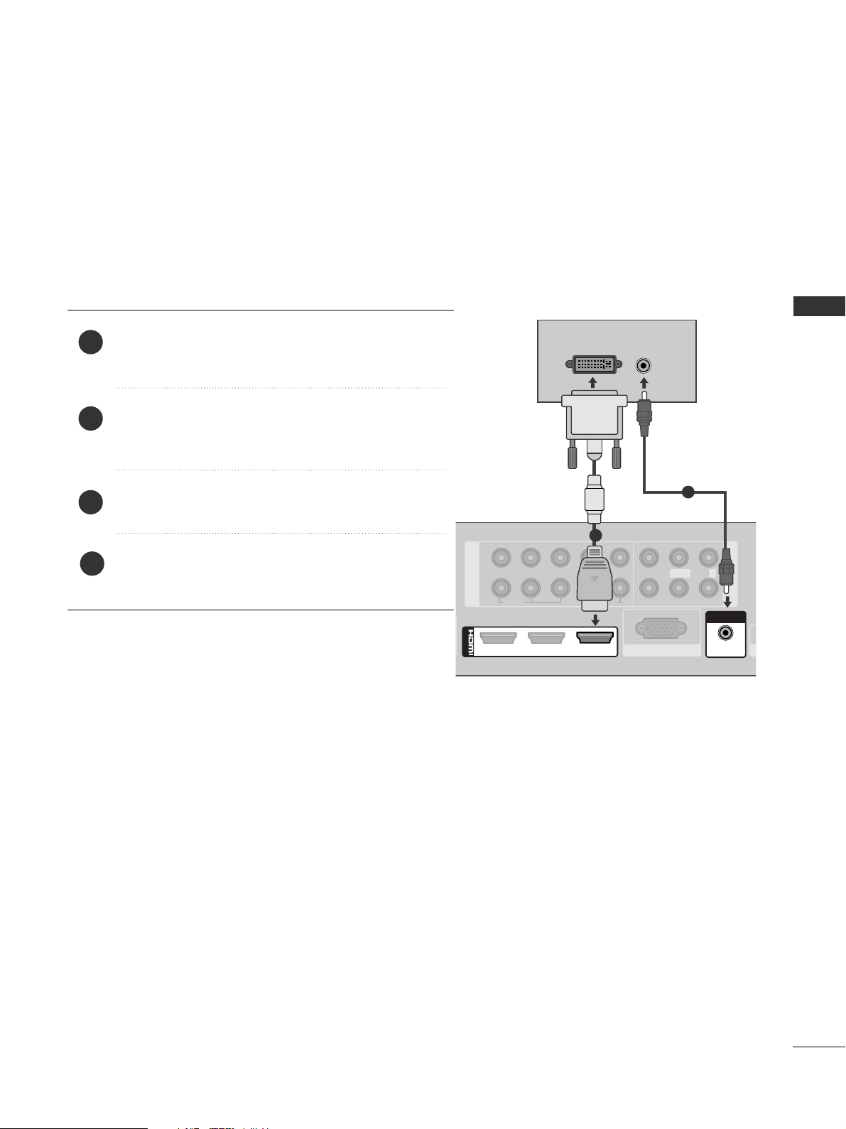
Connecting with a HDMI to DVI cable
1
2
4
Connect the DVI output of the PC to the
HHDDMMII//DDVVII
IINN 11
jack on the Media Box.
Connect the PC audio output to the
AAUU DDIIOO IINN
((RRGGBB// DDVV II))
jack on the Media Box.
Turn on the PC and the Media Box.
Select
HH DD MMII 11
input source using the INPUT button
on the remote control.
2
3
1
28
EXTERNAL EQUIPMENT SETUP
EXTERNAL EQUIPMENT SETUP
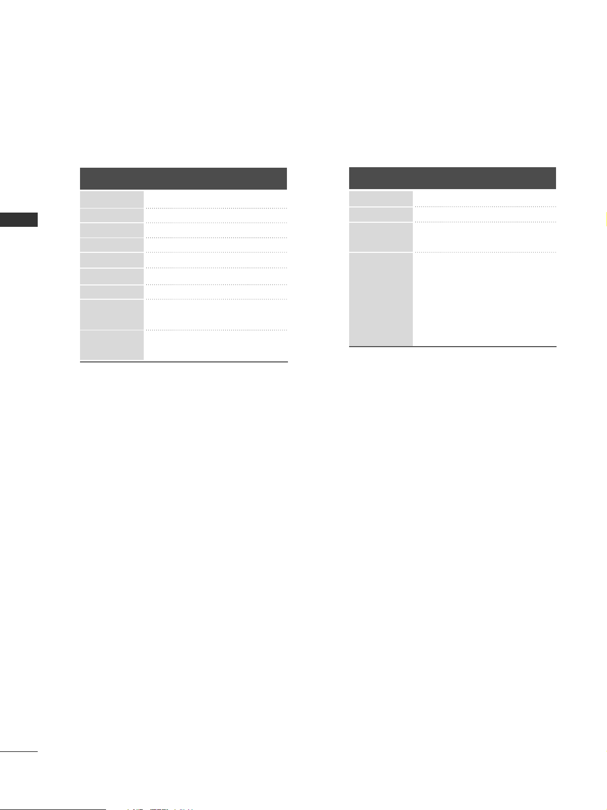
Supported Display Resolution
RGB-PC, HDMI/DVI-PC mode (except for HDMI 5)
70.08
59.94
60.31
60.00
59.87
59.80
60.00
59.93
60.00
31.468
31.469
37. 879
48.363
47. 78
47. 72
63.595
66.587
67. 5
720x400
640x480
800x600
1024x768
1280x768
1360x768
1280x1024
1920x1080
(RGB-PC)
1920x1080
(HDMI-PC)
Resolution
Horizontal
Frequency(kHz)
Vertical
Frequency(Hz)
HDMI/DVI-DTV mode
59.94/60
50
50
59.94/60
59.94/60
50
23.97/24
29.976/30.00
50
59.94/60
31.469/31.5
31.25
37. 5
44.96/45
33.72/33.75
28.125
26.97/27
33.716/33.75
56.25
67.43/67.5
Resolution
Horizontal
Frequency(kHz)
Vertical
Frequency(Hz)
720x480
720x576
1280x720
1920x1080
 Loading...