

LG 50LB650V, 50LB671V, 55LB870V, 47LB671V Owner’s Manual

OWNER’S MANUAL
*
LED TV
* LG LED TV applies LCD
screen with LED backlights.
Click! User Guide
Please read this manual carefully before operating your set and retain
it for future reference.
LB63** LB69** LB87**
LB65** LB72**
LB67** LB73**
LB68** LB86**
*MFL68027013*
www.lg.com
P/NO : MFL68027013(1403-REV00)
Printed in Korea

A-2
TABLE OF CONTENTS
TABLE OF CONTENTS
A-3 SETTING UP THE TV
A-3 Attaching the stand
A-8 Attaching the Sound Bar Supporter
A-9 Tidying cables
A-11 MAKING CONNECTIONS
A-11 Antenna connection
A-12 Satellite dish connection
A-12 HDMI connection
A-14 - ARC (Audio Return Channel)
A-14 DVI to HDMI connection
A-16 Component connection
A-17 Composite connection
A-19 MHL connection
A-20 Audio connection
A-20 - Digital optical audio connection
A-21 USB connection
A-22 CI module connection
A-23 Headphone connection
A-24 Euro Scart connection
COMMON
LANGUAGE LIST
English
Français
B-1 SPECIFICATIONS
LANGUAGE
COMMON
SETTING UP THE TV
1
2
1
2
A-3
SETTING UP THE TV
Image shown may differ from your TV.
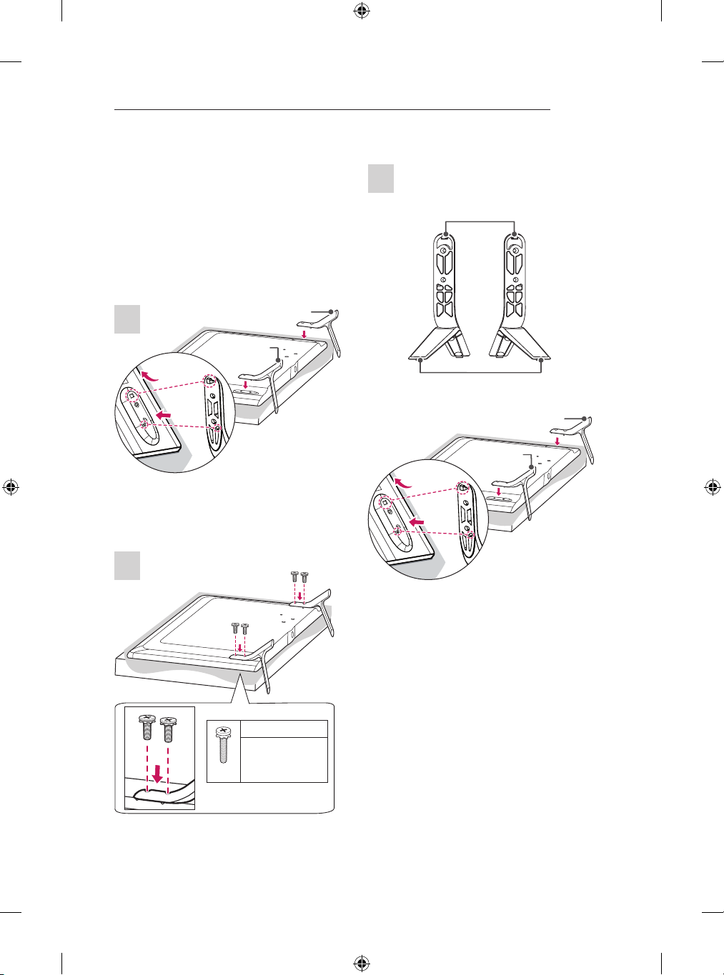
Attaching the stand
LB63**-ZA, 32/39/42/47/50/55LB65**-ZA
A stand base
1
B stand base
1 Attach the stand to the TV using the upper
mounting hole on the back of the TV.
2 Attach the stand to the TV using the lower
connection on the back of the TV.
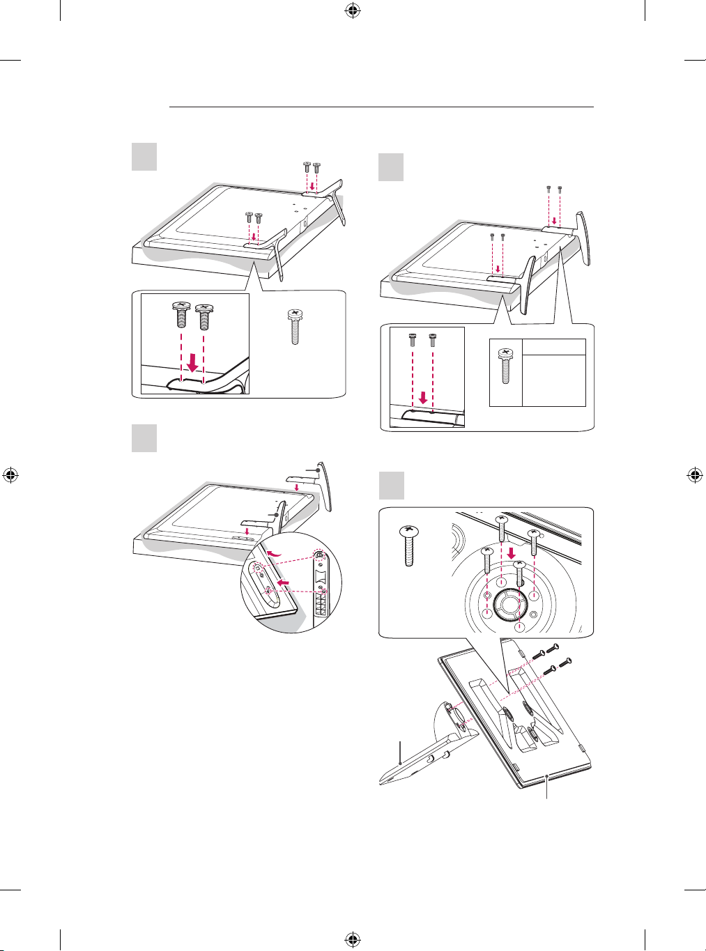
70LB65**-ZA, LB67**, LB68**, LB69**, LB73**-ZA
1
Stand Body
Stand Base
A stand Assy
B stand Assy
2
1 Attach the stand to the TV using the upper
mounting hole on the back of the TV.
2 Attach the stand to the TV using the lower
connection on the back of the TV.
M4 x L14
M4 x L20
(Only 32LB65**ZA)
4EA
A-4
2
1
2
1
SETTING UP THE TV
2
LB63**-ZL, LB65**-ZK
1
B stand base
4EA
M4 x L14
A stand base
2
32/39LB65**-ZE/ZN
1
4EA
M4 x L14
M4 x L20
(Only
32LB65**ZK)
4EA
M4 x L20
1
1 Attach the stand to the TV using the upper
mounting hole on the back of the TV.
2 Attach the stand to the TV using the lower
connection on the back of the TV.
Stand Body
Stand Base
SETTING UP THE TV
A-5
2
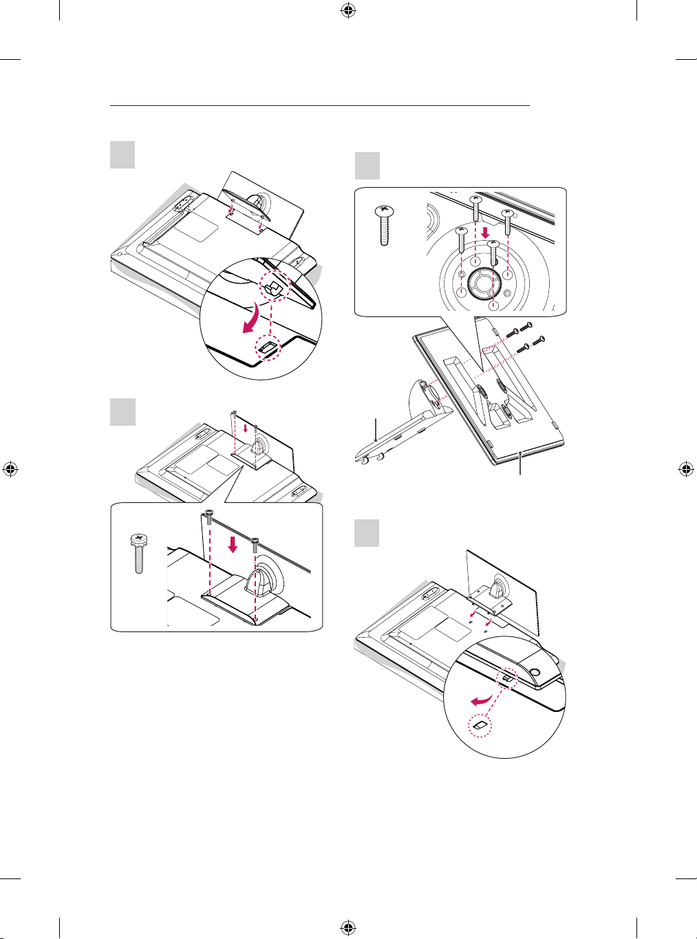
42/47/50/55/60LB65**-ZE/ZN
1
4EA
M4 x L20
1
3
Stand Body
Stand Base
2
2EA
M4 x L20

A-6
1
2
SETTING UP THE TV
3
4EA
M4 x L14
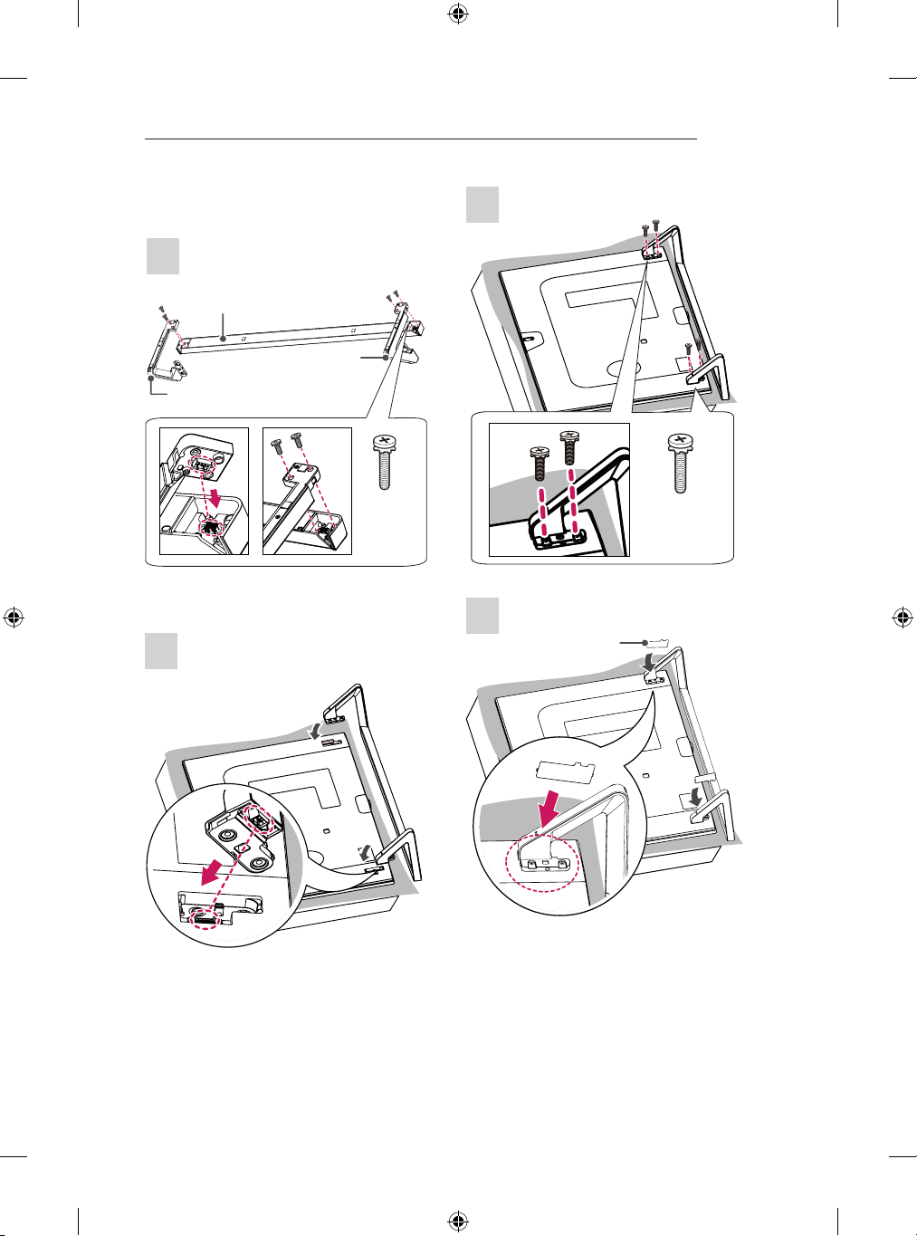
LB72**, LB73**-ZD/ZE
1
Stand Front
B Stand
Supporter
A Stand
Supporter
3
1 Attach the stand to the TV using the upper
mounting hole on the back of the TV.
2 Attach the stand to the TV using the lower
connection on the back of the TV.
4
2
4EA
M4 x L10
4EA
M4 x L14
SETTING UP THE TV
A-7
LB86**, LB87**
1
Sound Bar
Stand Assy Left
2
Stand Assy Right
4EA
M4 x L14
3
4EA
M4 x L14
4
Screw Cover
A-8
SETTING UP THE TV
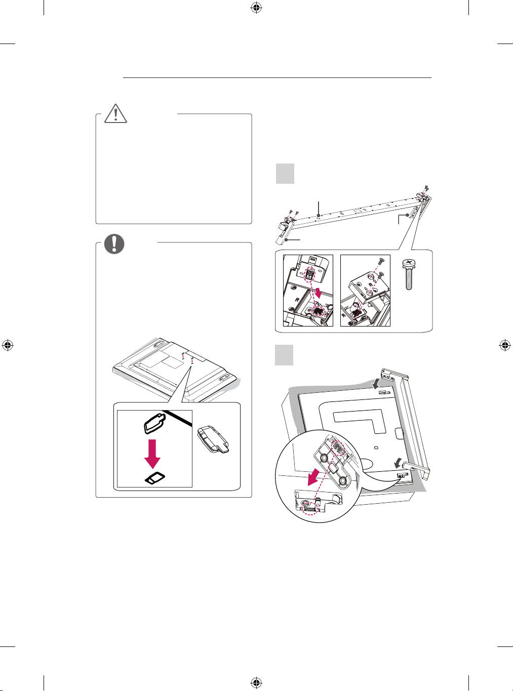
CAUTION
yWhen attaching the stand to the TV
set, place the screen facing down on a
cushioned table or flat surface to protect
the screen from scratches.
yMake sure that the screws are inserted
correctly and fastened securely. (If they
are not fastened securely enough, the TV
may tilt forward after being installed.)
Do not use too much force and over
tighten the screws; otherwise screw may
be damaged and not tighten correctly.
NOTE
yRemove the stand before installing the
TV on a wall mount by performing the
stand attachment in reverse.
yThe Screw Cover will protect the opening
from accumulating dust and dirty.
yThe Rubber will protect the opening from
accumulating dust and dirt. When
installing the wall mounting bracket, use
the Rubber. (Only LB65**-ZE/ZN)
Attaching the Sound Bar
Supporter
(In case of mounting on a wall)
LB86**, LB87**
1
Sound Bar
Sound Bar Supporter Right
Sound Bar Supporter Left
M4 x L14
2
4EA
Rubber

SETTING UP THE TV
A-9
3
CAUTION
yWhen attaching the sound bar supporter
to the TV set, place the screen facing
down on a cushioned table or flat surface
to protect the screen from scratches.
yMake sure that the screws are inserted
correctly and fastened securely. (If they
are not fastened securely enough, the TV
may tilt forward after being installed.)
Do not use too much force and over
tighten the screws; otherwise screw may
be damaged and not tighten correctly.
yThe sound bar supporter only uses for
wall mounting.
NOTE
4EA
M4 x L14
yRemove the sound bar supporter before
installing the stand by performing the
stand attachment in reverse.
yThe Screw Cover will protect the opening
from accumulating dust and dirty.
4
Screw Cover
Tidying cables
Image shown may differ from your TV.
1 Gather and bind the cables with the Cable
Holder. (Depending on model)
2 Fix the Cable Management rmly to the TV.
(Only 32LB65**-ZA)
Cable Management

A-10
SETTING UP THE TV
(Only LB63**-ZA, 39/42/47/50/55/60LB65**-ZA,
LB67**, LB68**, LB69**, LB73**-ZA)
(Only 32LB65**-ZK)
(Only LB63**-ZL, 39/42/47/50/55/60/70LB65**ZK/ZL)
Cable Holder
Cable Management
Cable Management
Cable Holder
(Only 70LB65**)
Cable Holder
Cable Management
(Only LB72**, LB73**-ZD/ZE)
Cable Holder
Cable Management
(Only LB86**, LB87**)
Cable Holder
(Only LB65**-ZE/ZN)
Cable Management
Cable Holder
Cable Management
CAUTION
yDo not move the TV by holding the cable
holders, as the cable holders may break,
and injuries and damage to the TV may
occur.

MAKING CONNECTIONS
A-11
MAKING CONNECTIONS
This section on MAKING CONNECTIONS mainly
uses diagrams for the LB67** models.
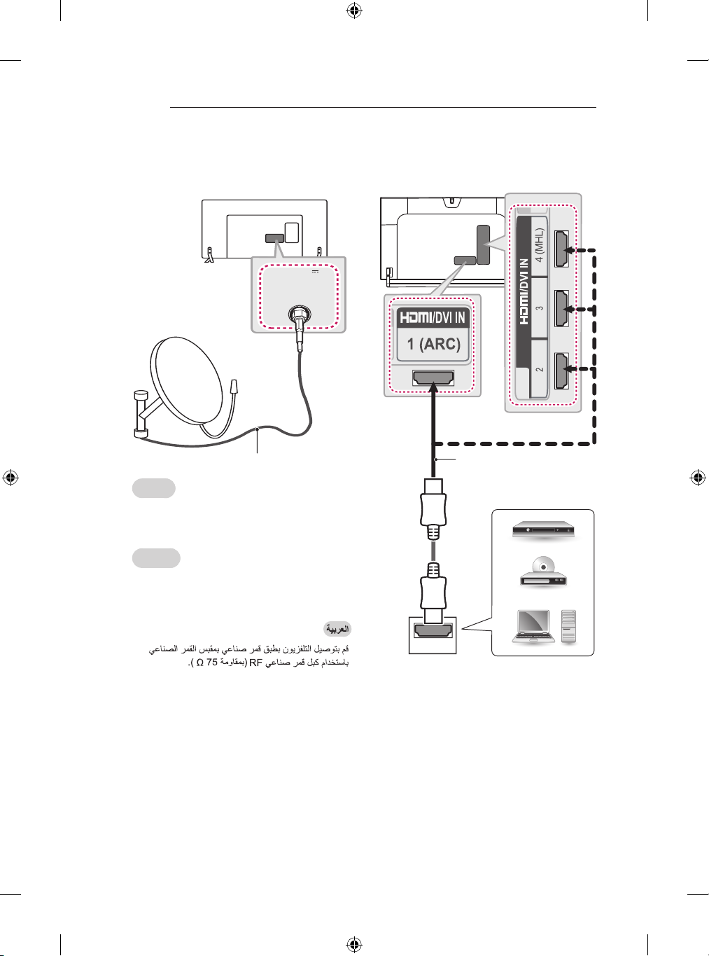
Antenna connection
ANTENNA /
CABLE IN
(*Not Provided)
English
Connect the TV to a wall antenna socket with an
RF cable (75 Ω).
NOTE
Use a signal splitter to use more than 2
y
TVs.
yIf the image quality is poor, install a signal
amplifier properly to improve the image
quality.
yIf the image quality is poor with an
antenna connected, try to realign the
antenna in the correct direction.
An antenna cable and converter are not
y
supplied.
ySupported DTV Audio: MPEG, Dolby
Digital, Dolby Digital Plus, HE-AAC
Français
Connectez la TV à une prise d’antenne murale
avec un câble RF (75 Ω).
REMARQUE
Utilisez un séparateur de signaux pour
y
utiliser plus de deux téléviseurs.
Si la qualité d’image est mauvaise,
y
installez correctement un amplificateur
de signaux pour l’améliorer.
Si vous utilisez une antenne et que la
y
qualité d’image est mauvaise, essayez
de réaligner l’antenne dans la bonne
direction.
yLe câble et le convertisseur d’antenne ne
sont pas fournis.
Technologies audio TNT prises en
y
charge : MPEG, Dolby Digital, Dolby
Digital Plus, HE-AAC
●
●
●
●
●
A-12
LNB
Satellite IN
13/18V
700mA Max
MAKING CONNECTIONS
Satellite dish connection
(Only satellite models)
(*Not Provided)
English
Connect the TV to a satellite dish to a satellite
socket with a satellite RF cable (75 Ω).
HDMI connection
(Only LB86**, LB87**)
(*Not Provided)
Français
Connectez la TV à une parabole satellite ou à
une prise satellite à l’aide d’un câble satellite RF
(75 Ω).
HDMI
DVD / Blu-Ray / HD Cable
Box / HD STB / PC

MAKING CONNECTIONS
A-13
(Only LB63**, LB65**, LB67**, LB68**, LB69**,
LB72**, LB73**)
DVD / Blu-Ray / HD Cable
Box / HD STB / PC
(*Not Provided)
HDMI
Français
Permet de transmettre les signaux vidéo et audio
numériques d’un périphérique externe vers la TV.
Connectez le périphérique externe et la TV avec
le câble HDMI comme indiqué sur l’illustration
suivante.
Choisissez un port d’entrée HDMI pour établir la
connexion. Peu importe le port que vous utilisez.
REMARQUE
Pour obtenir une meilleure qualité
y
d’image, il est recommandé d’utiliser la
TV avec une connexion HDMI.
yUtilisez le tout nouveau câble haut débit
HDMI™ avec la fonction CEC (contrôles
électroniques client).
Les câbles HDMI™ haut débit sont testés
y
pour transporter un signal HD de 1080p
ou supérieur.
yFormats audio HDMI pris en charge :
Dolby Digital, DTS, PCM (jusqu’à
192 KHz, 32KHz/44,1KHz/48KHz/88KHz/
96KHz/176KHz/192KHz)
English
Transmits the digital video and audio signals from
an external device to the TV. Connect the external
device and the TV with the HDMI cable as shown.
Choose any HDMI input port to connect. It does
not matter which port you use.
NOTE
It is recommended to use the TV with
y
the HDMI connection for the best image
quality.
Use the latest High Speed HDMI™ Cable
y
with CEC (Customer Electronics Control)
function.
High Speed HDMI™ Cables are tested to
y
carry an HD signal up to 1080p and higher.
Supported HDMI Audio format : Dolby
y
Digital, DTS, PCM (Up to 192 KHz, 32KHz
/44.1KHz/48KHz/88KHz/96KHz/176KHz/1
92KHz)
●
●
●
●

A-14
MAKING CONNECTIONS
ARC (Audio Return Channel)
English
An external audio device that supports
y
SIMPLINK and ARC must be connected
using HDMI IN 1 (ARC) or HDMI/DVI IN 1
(ARC) port.
When connected with a high-speed
y
HDMI cable, the external audio device
that supports ARC outputs optical SPDIF
without additional optical audio cable and
supports the SIMPLINK function.
Français
Un périphérique audio externe prenant
y
en charge SIMPLINK et ARC doit être
connecté à l’aide du port HDMI IN 1 (ARC)
ou HDMI/DVI IN 1 (ARC).
Si vous reliez un câble HDMI haut débit,
y
le périphérique audio externe qui prend en
charge les sorties ARC, prend également
en charge la sortie optique SPDIF sans
câble audio optique supplémentaire, ainsi
que la fonction SIMPLINK.
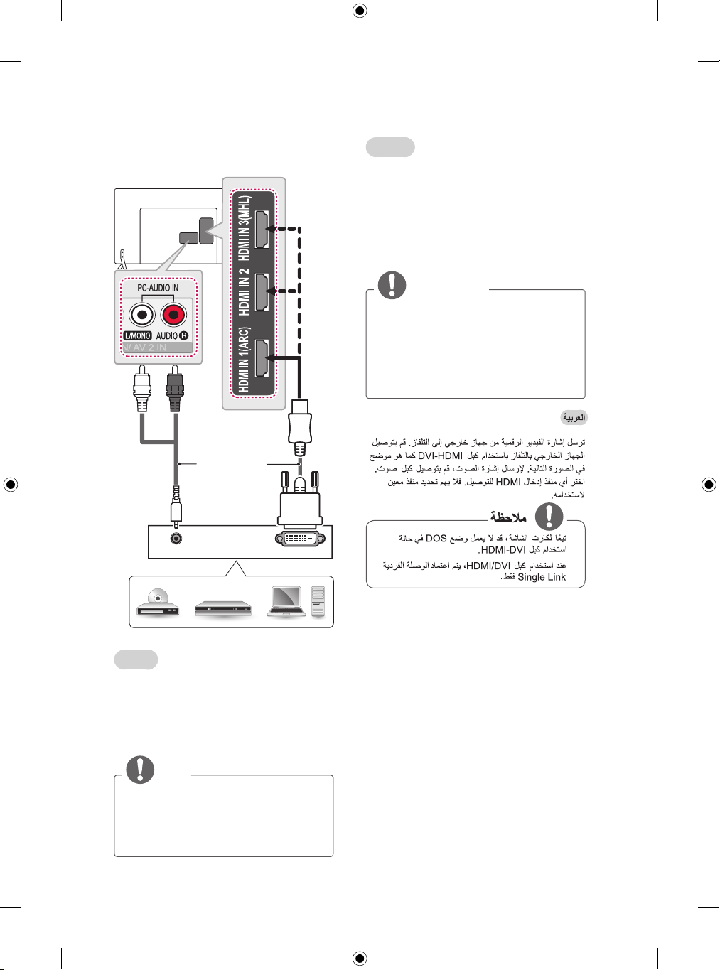
DVI to HDMI connection
(Only LB86**, LB87**)
YELLOW
y
y
(*Not Provided)
DVD / Blu-Ray / HD Cable Box / HD STB / PC
MAKING CONNECTIONS
DVI OUT
AUDIO OUT
A-15
(Only LB63**, LB65**, LB67**, LB68**, LB69**,
LB72**, LB73**)
WHITE
RED
(*Not Provided)
Français
Permet de transmettre les signaux vidéo d’un
périphérique externe vers la TV. Connectez le
périphérique externe et la TV avec le câble DVIHDMI comme indiqué sur l’illustration suivante.
Pour émettre un signal audio, raccordez un câble
audio.
Choisissez un port d’entrée HDMI pour établir la
connexion. Peu importe le port que vous utilisez.
REMARQUE
Selon la carte graphique, le mode DOS
y
peut ne pas fonctionner si vous utilisez
un câble pour établir la connexion HDMIDVI.
Lors de l’utilisation du câble HDMI/DVI,
y
seule une liaison unique peut être prise
en charge.
●
DVD / Blu-Ray / HD Cable Box / HD STB / PC
English
Transmits the digital video signal from an external
device to the TV. Connect the external device and
the TV with the DVI-HDMI cable as shown. To
transmit an audio signal, connect an audio cable.
Choose any HDMI input port to connect. It does
not matter which port you use.
NOTE
Depending on the graphics card, DOS
y
mode may not work if a HDMI to DVI Cable
is in use.
yWhen using the HDMI/DVI cable, only
Single link is supported.
●

A-16
MAKING CONNECTIONS
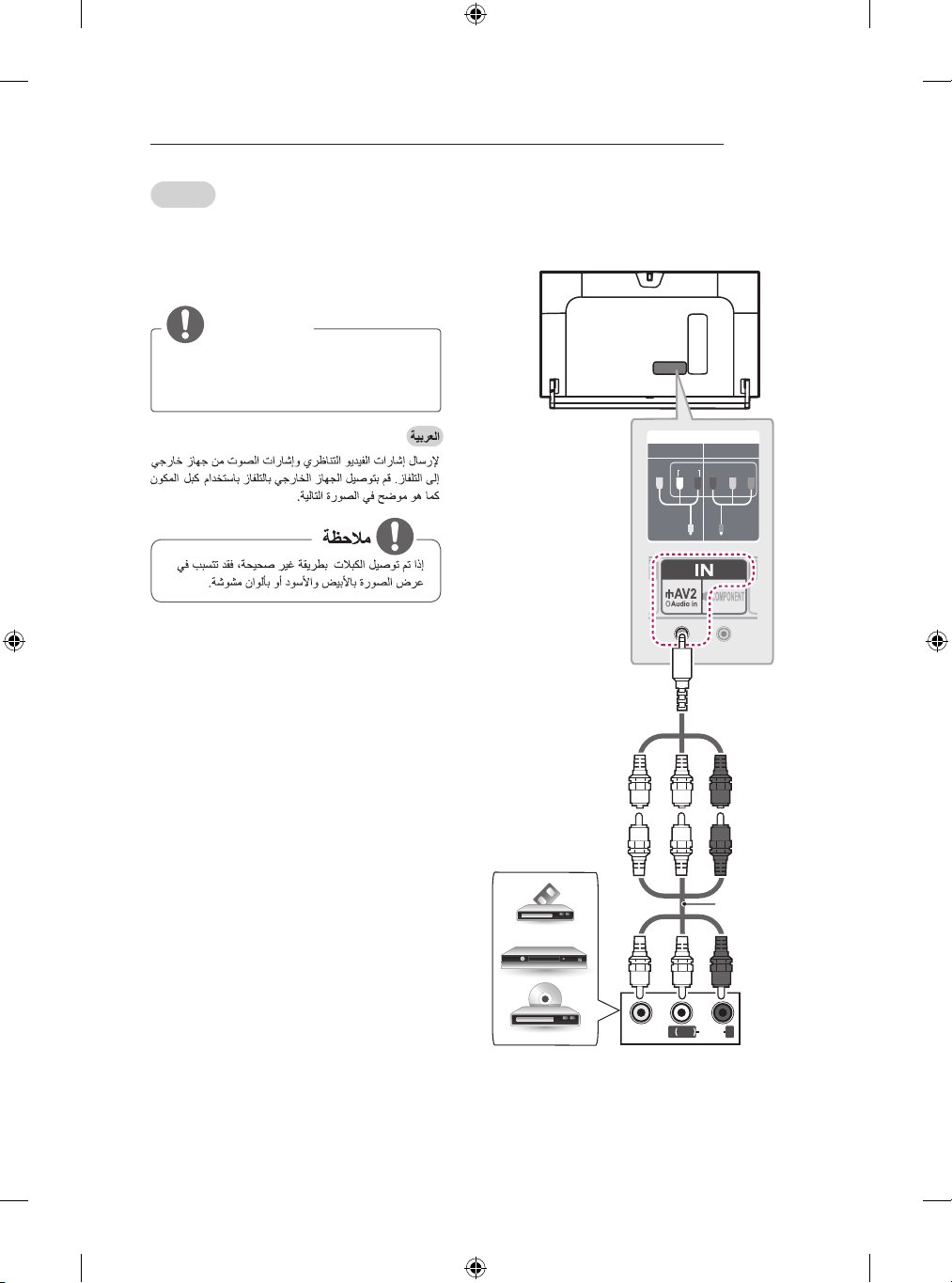
Component connection
(Only LB86**, LB87**)
IN
COMPONENT
VIDEO
(Use the composite
YELLOW
gender cable
provided.)
YELLOW
WHITE
AV2
AUDIO
P
RED
R
P Y
B
GREEN
(Use the
component gender
cable provided.)
RED
BLUE
GREEN
(Only LB63**, LB65**, LB67**, LB68**, LB69**,
LB72**, LB73**)
GREEN
GREEN
BLUE
Provided)
BLUE
RED
(*Not
RED
WHITE
WHITE
L R
RED
RED
WHITE
RED
(*Not
Provided)
WHITE
RED
L R
AUDIO
DVD / Blu-Ray / HD Cable Box
RED
RED
VIDEO
BLUE
BLUE
GREEN
GREEN
VIDEO
DVD / Blu-Ray / HD Cable Box
English
Transmits analog video and audio signals from an
external device to the TV. Connect the external
device and the TV with a component cable as
shown.
AUDIO
NOTE
yIf cables are not installed correctly, it
could cause this image to display in black
and white or with distorted colours.
MAKING CONNECTIONS
A-17
Français
Permet de transmettre les signaux audio et vidéo
analogiques d’un périphérique externe vers la
TV. Connectez le périphérique externe et la TV
avec un câble composante comme indiqué sur
l’illustration suivante.
REMARQUE
Si les câbles sont mal installés, l’image
y
peut s’afficher en noir et blanc ou avec
des couleurs de mauvaise qualité.
Composite connection
(Only LB86**, LB87**)
y
(Use the composite
VIDEO
YELLOW
gender cable
provided.)
YELLOW
AV2
IN
AUDIO
WHITE
COMPONENT
B
P
R
P Y
RED
DVD / Blu-Ray / HD
Cable Box / VCR
VIDEO
YELLOW
WHITE
YELLOW
WHITE
( )
MONO
AUDIOL R
RED
(*Not
Provided)
RED

A-18
MAKING CONNECTIONS
(Only LB63**, LB65**, LB67**, LB68**, LB69**,
LB72**, LB73**)
YELLOW
YELLOW
WHITE
WHITE
(*Not Provided)
RED
RED
English
Transmits analog video and audio signals from an
external device to the TV. Connect the external
device and the TV with the composite cable as
shown.
Français
Permet de transmettre les signaux audio et vidéo
analogiques d’un périphérique externe vers la
TV. Connectez le périphérique externe et la TV
avec le câble composite comme indiqué sur
l’illustration suivante.
VIDEO
DVD/ Blu-Ray / HD Cable Box / VCR
( )
MONO
AUDIOL R

MAKING CONNECTIONS
A-19
MHL connection
MHL passive cable
(*Not Provided)
Mobile phone
Français
Mobile High-denition Link (MHL) est une
interface qui permet de transmettre des signaux
audiovisuels numériques depuis des téléphones
portables vers des téléviseurs.
REMARQUE
Connectez le téléphone portable au port
y
HDMI IN 3 (MHL)
pour afficher l’écran du téléphone sur le
téléviseur.
Le câble passif MHL sert à connecter la
y
TV à un téléphone portable.
Cette fonctionnalité est uniquement
y
disponibles sur les téléphones prenant en
charge la connexion MHL.
Certaines applications peuvent être
y
utilisées depuis la télécommande.
Vous pouvez utiliser la télécommande
y
Magic sur certains téléphones portables
prenant en charge la connexion MHL.
Retirez le câble passif MHL du téléviseur
y
uniquement si :
- la fonction MHL est désactivée,
- votre périphérique mobile est
complètement chargé et en mode veille
ou
HDMI/DVI IN 4 (MHL)
)
English
Mobile High-denition Link (MHL) is an interface for
transmitting digital audiovisual signals from mobile
phones to television sets.
NOTE
Connect the mobile phone to the HDMI IN 3
y
(MHL) or HDMI/DVI IN 4 (MHL) port to view
the phone screen on the TV.
The MHL passive cable is needed to
y
connect the TV and a mobile phone.
This only works for the MHL-enabled phone.
y
Some applications can be operated by the
y
remote control.
For some mobile phones supporting MHL,
y
you can control with the magic remote
control.
Remove the MHL passive cable from the TV
y
when:
- the MHL function is disabled
- your mobile device is fully charged in
standby mode
●
●
●
●
●

A-20
MAKING CONNECTIONS
Audio connection
(*Not Provided)
OPTICAL
AUDIO IN
Digital Audio System
English
You may use an optional external audio system
instead of the built-in speaker.
Digital optical audio connection
Français
Vous pouvez utiliser un système audio externe en
option à la place d’un haut-parleur intégré.
Connexion audio optique
numérique
Permet de transmettre un signal audio numérique
de la TV au périphérique externe. Connectez le
périphérique externe et la TV avec le câble audio
optique comme indiqué sur l’illustration suivante.
REMARQUE
Ne regardez pas dans le port de sortie
y
optique. Le rayon laser risquerait de vous
abîmer la vue.
La fonction Audio avec ACP (protection
y
copie audio) peut bloquer la sortie audio
numérique.
●
●
Transmits a digital audio signal from the TV to an
external device. Connect the external device and
the TV with the optical audio cable as shown.
NOTE
Do not look into the optical output port.
y
Looking at the laser beam may damage
your vision.
Audio with ACP (Audio Copy Protection)
y
function may block digital audio output.

MAKING CONNECTIONS
A-21
USB connection
HUB
HDD
(*Not
Provided)
English
Connect a USB storage device such as a USB
ash memory, external hard drive, or a USB
memory card reader to the TV and access the
SmartShare menu to use various multimedia les.
(*Not Provided)
USB
(*Not
Provided)
Français
Connectez un périphérique de stockage USB
comme une clé USB, un disque dur externe ou
une carte mémoire USB à la TV et accédez au
menu SmartShare pour utiliser divers chiers
multimédia.
REMARQUE
Certains ports USB peuvent ne pas
y
fonctionner. Si un appareil USB branché
sur un port USB n’est pas détecté alors
connectez-le directement au téléviseur.
Connectez la source d’alimentation
y
externe si une connexion USB est
nécessaire.
●
●
NOTE
Some USB Hubs may not work. If a USB
y
device connected using a USB Hub is not
detected, connect it to the USB port on
the TV directly.
Connect the external power source if your
y
USB is needed.

A-22
MAKING CONNECTIONS
CI module connection
(*Not Provided)
Français
Afchez les services cryptés (payants) en mode
TV numérique. Cette fonction n’est pas disponible
dans tous les pays.
REMARQUE
Vérifiez si le module CI est inséré dans
y
le bon sens dans la fente de la carte
PCMCIA. Si le module est mal inséré, la
TV pourrait subir des dommages ainsi
que la fente de la carte PCMCIA.
Si le téléviseur n’affiche aucune vidéo et
y
n’émet aucun son lorsque l’entrée CI+
CAM est connectée, contactez votre
opérateur de service terrestre/satellite/
câble.
y
y
English
View the encrypted (pay) services in digital
TV mode. This feature is not available in all
countries.
NOTE
Check if the CI module is inserted into the
y
PCMCIA card slot in the right direction. If
the module is not inserted properly, this
can cause damage to the TV and the
PCMCIA card slot.
If the TV does not display any video
y
and audio when CI+ CAM is connected,
please contact to the Terrestrial/Cable/
Satellite Service Operator.

MAKING CONNECTIONS
Ext.Speaker / H/P OUT
A-23
Headphone connection
(*Not
Provided)
English
Transmits the headphone signal from the TV to
an external device. Connect the external device
and the TV with the headphone as shown.
NOTE
AUDIO menu items are disabled when
y
connecting a headphone.
yOptical Digital Audio Out is not available
when connecting a headphone.
yHeadphone impedance: 16 Ω
yMax audio output of headphone: 0.624
mW to 1.04 mW
Headphone jack size: 0.35 cm
y
Français
Transmet le signal du casque de la TV au
périphérique externe. Connectez le périphérique
externe et la TV avec le casque comme indiqué
sur l’illustration suivante.
REMARQUE
Les éléments du menu AUDIO sont
y
désactivés lorsque vous branchez un
casque.
La sortie audio numérique optique n’est
y
pas disponible lorsque vous branchez un
casque.
yImpédance du casque : 16 Ω
ySortie audio max. du casque : 0,624 mW
à 1,04 mW
yTaille de la prise casque : 0,35 cm
●
●
●
●
●

A-24
AV1
IN/OUT
MAKING CONNECTIONS
Euro Scart connection
(Only LB86**, LB87**)
(Use the Scart
gender cable
provided.)
(*Not Provided)
(Only LB63**, LB65**, LB67**, LB68**, LB69**,
LB72**, LB73**)
(*Not Provided)
MAKING CONNECTIONS
A-25
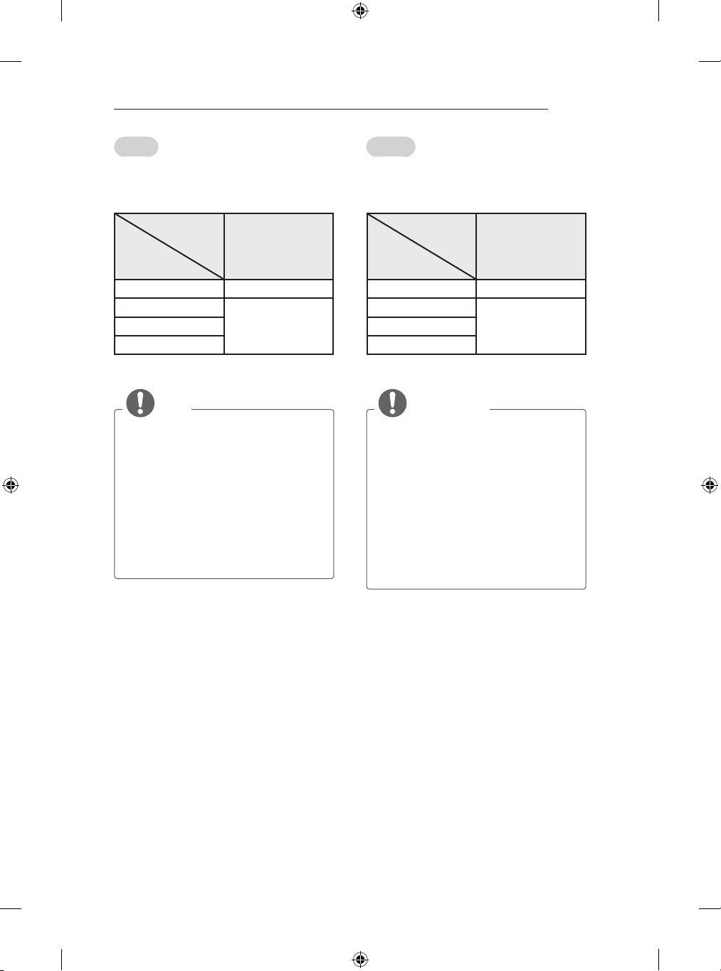
English
Transmits the video and audio signals from an external device to the TV set. Connect the external
device and the TV set with the euro scart cable
as shown.
Output
Type
Current
input mode
Digital TV Digital TV
Analogue TV, AV
HDMI
1 TV Out : Outputs Analogue TV or Digital TV
signals.
AV1
(TV Out1)
Analogue TVComponent
NOTE
Any Euro scart cable used must be signal
y
shielded.
When watching digital TV in 3D imaging
y
mode, only 2D out signals can be output
through the SCART cable. (Only 3D
models)
If you set the 3D mode to On while a
y
scheduled recording is performed on
digital TV, monitor out signals cannot be
output through the SCART cable, and the
recording cannot be performed. (Only 3D
models)
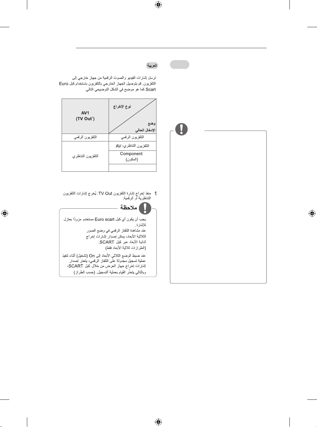
Français
Transmet les signaux audio et vidéo d’un appareil externe au téléviseur. Raccordez l’appareil
externe et le téléviseur à l’aide d’un câble péritel
comme illustré ci-dessous.
Type de sortie
AV1
Mode
d'entrée actuel
TV numérique TV numérique
TV analogique, AV
HDMI
1 Sortie TV : sortie de signaux en mode TV
analogique ou en mode TV numérique.
(Sortie TV1)
TV analogiqueComposant
REMARQUE
Tous les câbles Euro scart utilisés doivent
y
être des câbles de signal blindés.
Quand le mode 3D est sélectionné sur
y
la TV numérique, seuls les signaux de
sortie 2D peuvent être émis via le câble
péritel. (modèles 3D uniquement)
Si vous activez le mode 3D pendant
y
l’exécution d’un enregistrement
programmé sur la TV numérique,
les signaux de sortie ne peuvent
pas être émis via le câble péritel
et l’enregistrement est impossible.
(modèles 3D uniquement)
A-26
MAKING CONNECTIONS
HDMI
English
Connect various external devices to the TV
and switch input modes to select an external
device. For more information of external device’s
connection, refer to the manual provided with
each device.
Available external devices are: HD receivers,
DVD players, VCRs, audio systems, USB storage
devices, PC, gaming devices, and other external
devices.
NOTE
The external device connection may differ
y
from the model.
Connect external devices to the TV
y
regardless of the order of the TV port.
If you record a TV program on a DVD
y
recorder or VCR, make sure to connect
the TV signal input cable to the TV
through a DVD recorder or VCR. For
more information of recording, refer to
the manual provided with the connected
device.
Refer to the external equipment’s manual
y
for operating instructions.
If you connect a gaming device to the TV,
y
use the cable supplied with the gaming
●
●
●
device.
In PC mode, there may be noise
y
associated with the resolution, vertical
pattern, contrast or brightness. If noise is
present, change the PC output to another
resolution, change the refresh rate to
another rate or adjust the brightness and
contrast on the PICTURE menu until the
picture is clear.
In PC mode, some resolution settings
y
may not work properly depending on the
graphics card.

Français
Connectez divers périphériques externes à la
TV et changez de mode de source d’entrée pour
sélectionner un périphérique externe. Pour en
savoir plus sur le raccordement d’un périphérique
externe, reportez-vous au manuel fourni avec ce
dernier.
Les périphériques externes disponibles sont les
suivants : récepteurs HD, lecteurs DVD, VCR,
systèmes audio, périphériques de stockage USB,
PC, consoles de jeu et autres périphériques
externes.
REMARQUE
Le raccordement du périphérique externe
y
peut différer du modèle.
Connectez des périphériques externes à
y
la TV sans tenir compte de l’ordre du port
TV.
Si vous enregistrez un programme
y
TV sur un enregistreur de DVD ou un
magnétoscope, veillez à raccorder le
câble de source d’entrée du signal de la
TV à la TV via un enregistreur de DVD
ou un magnétoscope. Pour en savoir
plus sur l’enregistrement, reportez-vous
au manuel fourni avec le périphérique
connecté.
Veuillez consulter le manuel de
y
l’équipement externe contenant les
instructions d’utilisation.
Si vous connectez une console de jeu
y
à la TV, utilisez le câble fourni avec la
console de jeu.
En mode PC, un bruit peut être associé
y
à la résolution, au modèle vertical, au
contraste ou à la luminosité. En présence
de bruit, changez la résolution de la
sortie PC, changez le niveau du taux de
rafraîchissement ou réglez la luminosité
et le contraste dans le menu IMAGE
jusqu’à ce que l’image soit nette.
En mode PC, certains réglages de la
y
résolution peuvent ne pas fonctionner
correctement en fonction de la carte
graphique utilisée.
MAKING CONNECTIONS
A-27
●
●
●
●
●
●
●

OWNER’S MANUAL
*
LED TV
* LG LED TV applies LCD
screen with LED backlights.
Click! User Guide
Please read this manual carefully before operating your set and retain
it for future reference.
www.lg.com

2
TABLE OF CONTENTS
ENGLISH
TABLE OF CONTENTS
3 LICENSES
3 OPEN SOURCE SOFTWARE
NOTICE
3 EXTERNAL CONTROL DEVICE
SETUP
4 SAFETY INSTRUCTIONS
10 - Viewing 3D Imaging (Only 3D models)
12 INSTALLATION PROCEDURE
12 ASSEMBLING AND PREPARING
12 Unpacking
16 Separate purchase
17 Parts and buttons
19 - Using the Joystick button
20 Lifting and moving the TV
21 Mounting on a table
22 Mounting on a wall
23 Using Built-in Camera
24 - Preparing Built-in Camera
24 - Name of Parts of Built-in Camera
24 - Checking the Camera’s Shooting
Range
25 REMOTE CONTROL
29 USING THE USER GUIDE
30 MAINTENANCE
30 Cleaning your TV
30 - Screen, frame, cabinet and stand
30 - Power cord
30 TROUBLESHOOTING
31 SPECIFICATIONS
WARNING
yIf you ignore the warning message, you
may be seriously injured or there is a
possibility of accident or death.
27 MAGIC REMOTE FUNCTIONS
28 Registering Magic Remote
28 How to use Magic Remote
29 Precautions to Take when Using the
Magic Remote
CAUTION
yIf you ignore the caution message, you
may be slightly injured or the product may
be damaged.
NOTE
yThe note helps you understand and use
the product safely. Please read the note
carefully before using the product.
 Loading...