

LG 47LB5RE Owner’s Manual
Please read this manual carefully before operating
your
TV
Retain it for future reference.
Record model number and serial number of the
TV.
Refer to the label on the back cover and quote this
information
To your dealer when requiring service.
LCD TV
PLASMA TV
OWNER’S MANUAL
LCD TV MODELS
3322LLBB55RR
**
3377LLBB55RR
**
4422LLBB55RR
**
4477LLBB55RR
**
5522LLBB55RR
**
PLASMA TV MODELS
4422PPBB44 RR
**
5500PPBB44 RR
**
ENGLISH
TThhiiss ffeeaatt uurree iiss nnoott aavvaaiillaa bb llee
ffoorr aa llll mmooddeellss..
((4477LLBB55 RR**//5522LLBB55 RR**
oonnll yy))

ACCESSORIES
1
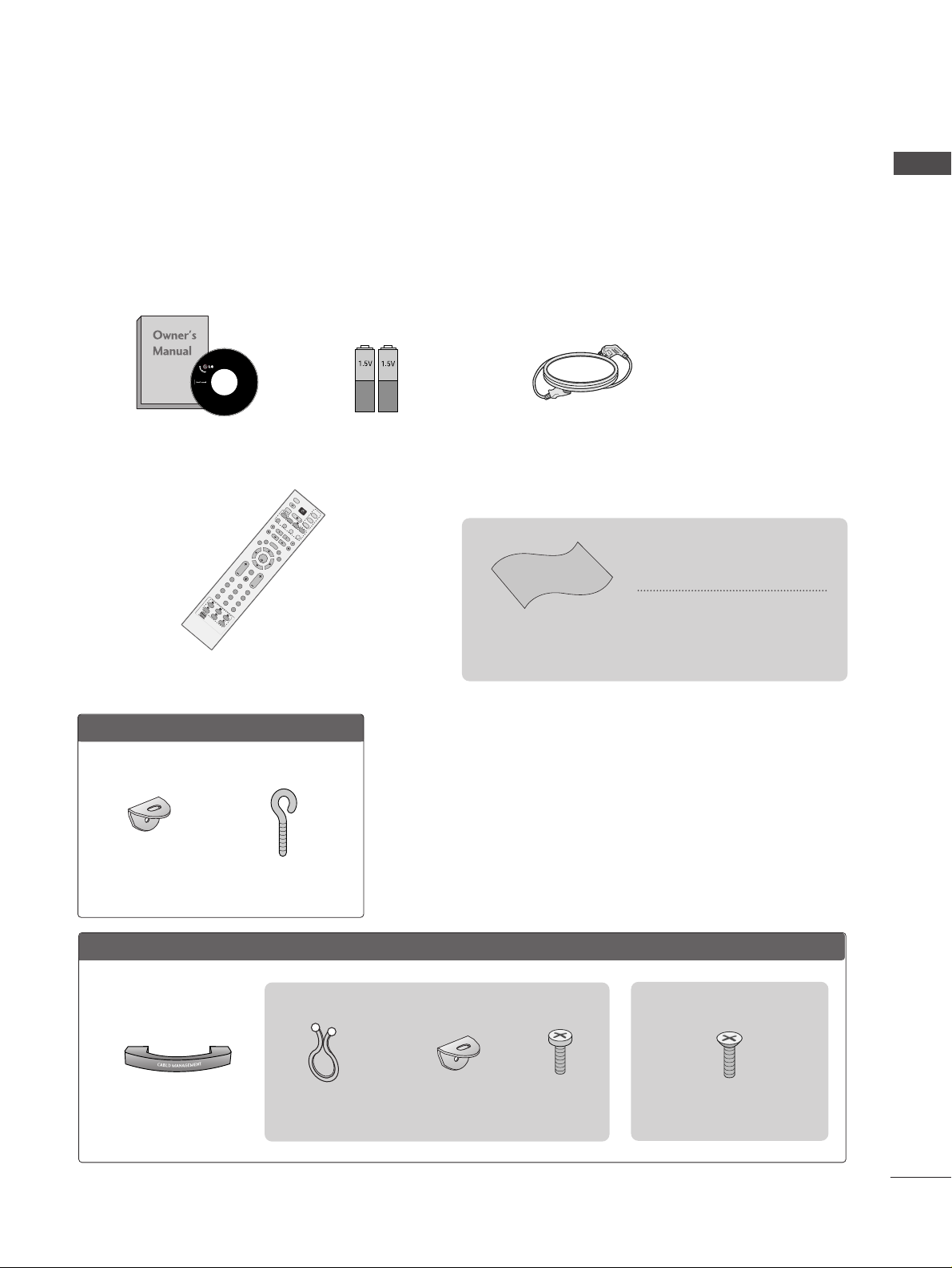
ACCESSORIES
Ensure that the following accessories are included with your TV. If an accessory is missing, please contact the
dealer where you purchased the product.
Owner’s Manual Batteries
Remote Control
Power Cord
LLCCDD TTVV mmooddeellss
Polishing Cloth
Polishing cloth for use on the
screen
*Lightly wipe any stains or finger-
prints on the surface of the TV with
the polishing cloth.
Do not use excessive force. This may
cause scratching or discolouration.
Cable management
OK
IN
P
U
T
M
O
D
E
T
V
T
V
D
V
D
RATIO
M
E
N
U
V
O
L
IO
N
INDEX
P
R
P
I
P
E
X
IT
T
IM
E
S
H
IF
T
T
I
M
E
S
H
I
F
T
L
I
S
T
L
I
V
E
T
V
I/II
T
IM
E
M
A
C
H
IN
E
V
C
R
PIP PR- PIP PR+
P
I
P
I
N
P
U
T
P
O
W
E
R
B
R
IG
H
T
123
456
789
0
FAV/
MARK
R
E
V
E
A
L
?
TE
X
T
SIMPLINK
I
N
P
U
T
M
U
T
E
S
W
A
P
OK
IN
P
U
T
M
O
D
E
TVT
V
D
V
D
RATIO
M
E
N
U
V
O
L
P
O
S
IT
IO
N
INDEX
P
R
P
IP
E
X
I
T
T
IM
E
S
H
IF
T
T
IM
E
S
H
IF
T
L
I
S
T
L
I
V
E
T
V
I/II
T
IM
E
M
A
C
H
IN
E
S
IZ
E
V
C
R
PIP PR- PIP PR+
P
IP
IN
P
U
T
P
O
W
E
R
123
456
789
0
FAV/
MARK
R
E
V
E
A
L
?
TE
X
T
SIMPLINK
I
N
P
U
T
M
U
T
E
T
IM
E
H
O
L
D
S
W
A
P
B
R
IG
H
T
S
L
E
E
P
Q
.V
IE
W
Q
.V
IE
W
PPllaassmmaa TTVV mmooddeellss
2-Wall brackets
2-eye-bolts
4-bolts for stand assembly
Refer to p. 9
3322”” ,, 3377”” oonn llyy
This feature is not available for all models.
This feature is not available for all models.
2- TV Brackets
2- Wall Brackets
2-bolts
Twists holder
Arrange the cables with
the twists
2
CONTENTS
CONTENTS
Remote Control Key Functions.................................34
Turning on the TV....................................................... 36
Programme Selection ................................................. 36
Volume Adjustment......................................................36
On Screen Menus Selection and Adjustment ......37
Auto Programme Tuning............................................ 38
Manual Programme Tuning ....................................... 39
Fine Tuning .....................................................................40
Assigning a Station Name ..........................................41
Booster............................................................................42
Programme Edit ........................................................... 43
Favourite Programme .................................................. 44
Calling the Programme List....................................... 45
Input Source Selection ...............................................46
Key lock.......................................................................... 47
................................................................. 48
WATCHING TV / PROGRAMME CONTROL
AACCCCEESSSSOORRIIEESS
.....................................................1
PREPARATION
Home Menu......................................................................4
Front Panel Controls..................................................... 5
Back Panel Information ................................................ 7
Stand Installation........................................................... 9
Attaching the TV to a Wall .........................................10
Back Cover for Wire Arrangement........................... 11
Desktop Pedestal Installation................................... 13
Wall Mount: Horizontal installation ........................ 13
Antenna Connection................................................... 14
EXTERNAL EQUIPMENT SETUP
HD Receiver Setup .......................................................15
DVD Setup..................................................................... 18
VCR Setup..................................................................... 21
Other A/V Source Setup........................................... 24
AV Output Setup ........................................................ 25
External Stereo Setup ................................................ 25
USB in Setup .................................................................26
PC Setup........................................................................27
- Screen Setup for PC Mode ...............................30
PREPARATION
TIME MACHINE
TimeShift Mode(Pause & Replay of Live TV)...... 50
Format hard disk ...........................................................53
Instant Recording.........................................................54
Manual Record ..............................................................56
Schedule List..................................................................57
Record Quality ..............................................................57
To use the USB device................................................58
Recorded TV Programme List ...................................60
USB Backup ..................................................................63
Photo List........................................................................66
Music List........................................................................70
Movie List........................................................................73
Subtitle............................................................................75
DivX Registration Code..............................................76

3
CONTENTS
PICTURE CONTROL
Watching PIP(Picture-in-Picture) .............................77
Picture Size (Aspect Ratio)Control.........................79
Preset Picture Settings
- Picture Mode-Preset............................................81
-
Auto Colour Temperature Control(Warm/Medium/Cool)
..82
Manual Picture Adjustment
- Picture Mode-User option.................................83
- Colour Temperature - User option..................84
-
Picture Improvement Technology
...................85
Demo .................................................................86
Advanced - Cinema......................................................87
Advanced - Black(Darkness) Level...........................88
Picture Reset..................................................................89
Image Sticking Minimization(ISM) Method ..........90
Low-Power Picture Mode............................................91
SOUND & LANGUAGE CONTROL
Auto Volume Leveler....................................................92
Preset Sound Settings - Sound Mode ....................93
Sound Setting Adjustment - User Mode ...............94
Balance ............................................................................95
TV Speakers On/Off Setup.......................................96
I/II
- Stereo/Dual Reception.......................................97
- NICAM Reception ................................................98
- Speaker Sound Output Selection....................98
On-Screen Menu Language Selection
...................... 99
PICTURE CONTROL
APPENDIX
Troubleshooting..........................................................107
Maintenance ...............................................................109
Product Specifications...............................................110
Programming the Remote Control ....................... 112
IR Codes ........................................................................114
External Control Device Setup................................116
TIME SETTING
Clock Setup .................................................................100
Auto On/Off Timer Setting......................................101
Sleep Timer Setting ...................................................102
Auto Shut-off Setting ................................................103
TELETEXT
Switch On/Off ...........................................................104
SIMPLE Text .................................................................104
TOP Text .......................................................................105
FASTEXT .......................................................................105
Special Teletext Functions .......................................106
4
HOME MENU
PREPARATION
PREPARATION
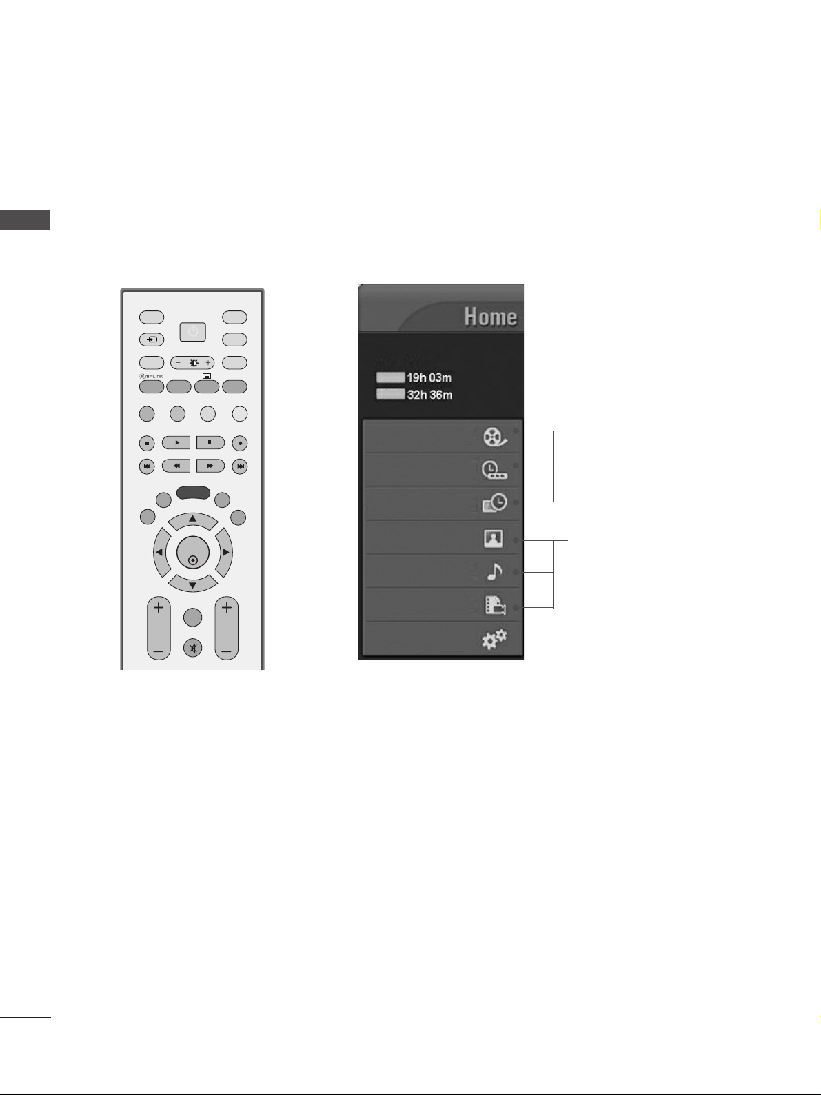
This menu is a contents guide.
In Home Menu, you enter the Recorded list of TIME MACHINE, Manual Recording of TIME MACHINE,
Schedule List ,Photo List, Music List, Movie List or TV Menu.
OK
INPUT MODE
TVTV
DVD
RATIO
MENU
VOL PR
PIP
EXIT
TIME
SHIFT
TIME
SHIFT
LIST
LIVE TV
I/II
TIME
MACHINE
VCR
PIP PR- PIP PR+
PIP INPUT
POWER
FAV/
MARK
TEXT
SIMPLINK
INPUT
MUTE
SWAP
BRIGHT
G
pp..5500
G
pp..6666~7744
Recorded TV
Manual Record
Schedule List
Photo List
Music List
Movie List
TV Menu
HIGH
NORMAL
TIME MACHINE
TIME MACHINE
Free Space
5
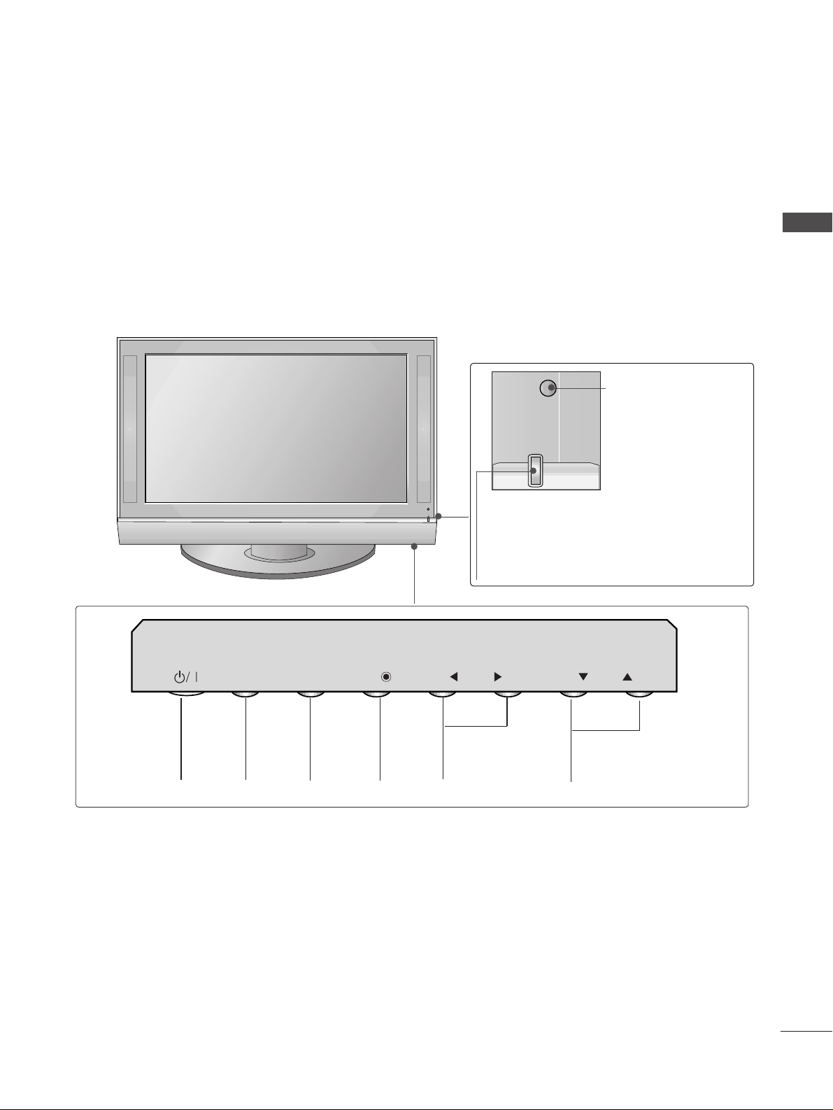
FRONT PANEL CONTROLS
PREPARATION
■
This is a simplified representation of the front panel. Image shown may differ from your TV.
■
If your TV has a protection film attached, remove the film and then wipe the product with a polishing cloth.
PROGRAMME
VOLUME
MENU
OK
INPUT
POWER
Plasma TV Models
Remote Control Sensor
Power/Standby Indicator
• illuminates red in standby mode.
• illuminates green when the TV is switched on.
• illuminates orange when the TV is switched off
during recording.
INPUT
MENU
OK
VOL
PR
6
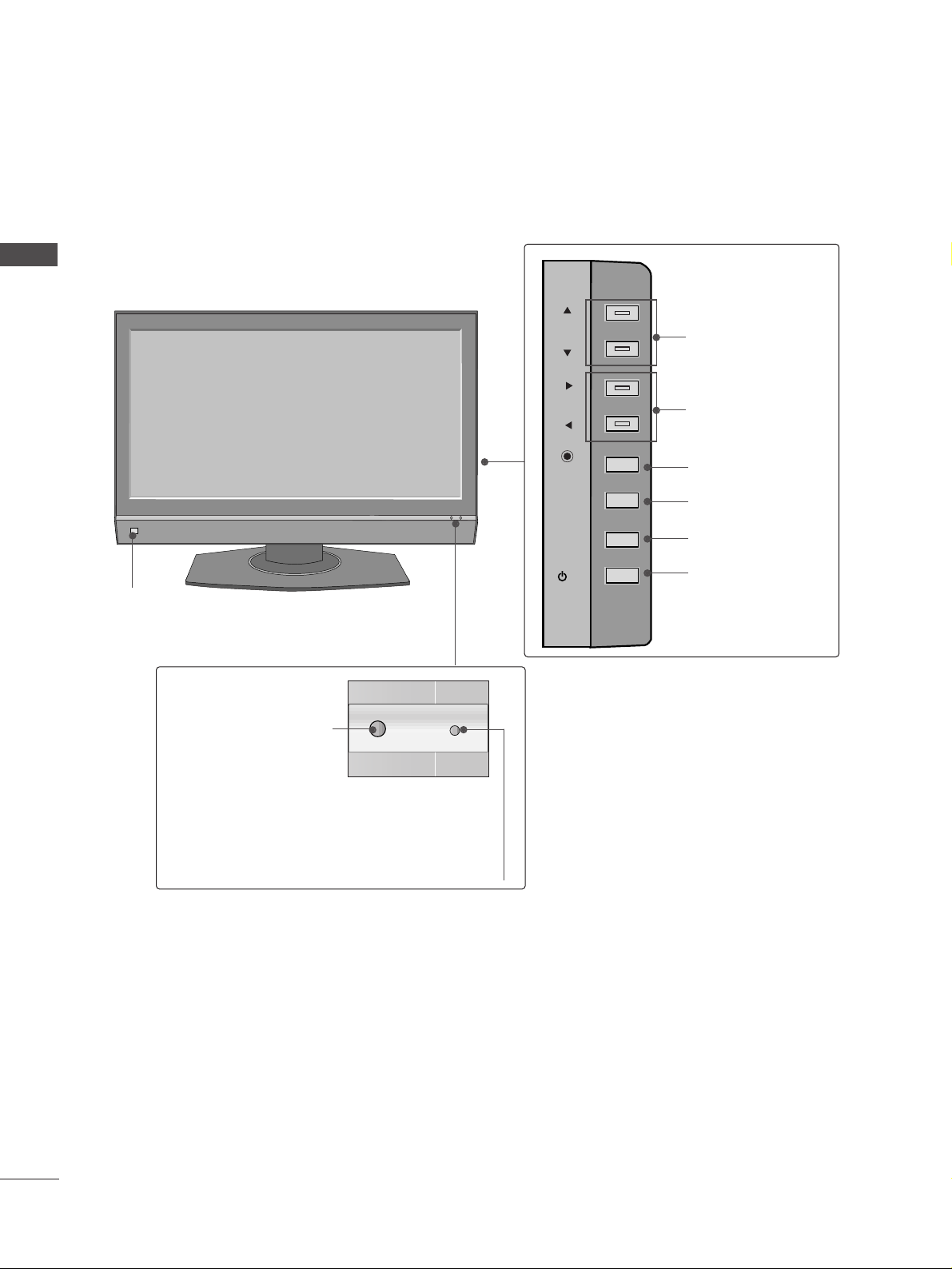
PREPARATION
PREPARATION
LCD TV Models
PR
VOL
OK
MENU
INPUT
/I
PROGRAMME
VOLUME
OK
MENU
INPUT
POWER
Intelligent Eye
Adjusts picture according to the
surrounding conditions.
Remote Control Sensor
Power/Standby Indicator
• illuminates red in standby mode.
• illuminates green when the TV is switched on.
• illuminates orange when the TV is switched off during
recording.
HDMI IN HDMI IN HDMI/DHDMI/DVI IN VI IN
1
2
2
1
VARIABLE AARIABLE AUDIO OUTUDIO OUT
AUDIO
(RGB/DVI)
RGB
(PC)
RGB INRGB IN
COMPONENT INCOMPONENT IN
AUDIO
VIDEO
AV IN 1V IN 1 AV OUTV OUT
L/L/M
ONO
MONO
R
AUDIOAUDIO
VIDEOVIDEO
ANTENNA
IN
RS-232C IN
(CONTROL&
SER
OL&SERVICE)
USB
AV IN 2
L/ MONO
R
AUDIO
VIDEO
S-VIDEO
7
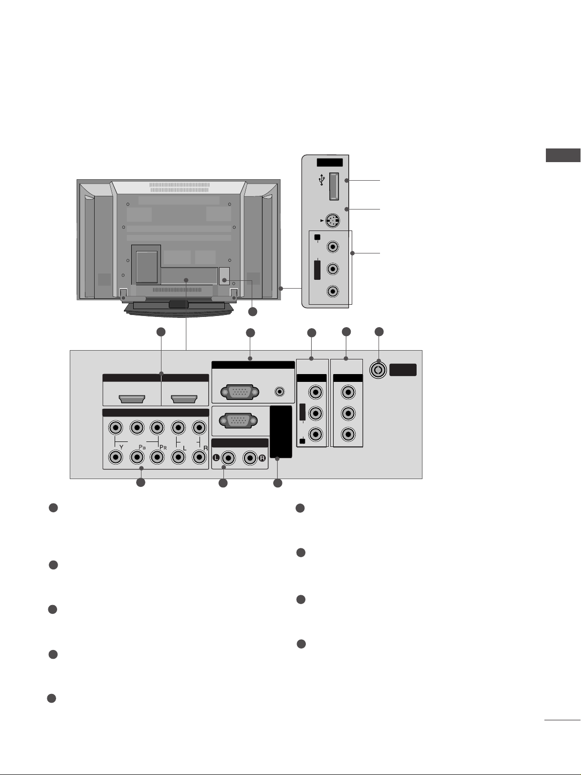
BACK PANEL INFORMATION
PREPARATION
■
This is a simplified representation of the back panel. Image shown may differ from your TV.
Plasma TV Models
USB
AV IN 2
L/ MONO
R
AUDIO
S-VIDEO
1
4
7 8
6
USB Input
S-Video Input
Connect S-Video out from an
S-VIDEO device.
Audio/Video Input
Connect audio/video output
from an external device to
these jacks.
USBUSB
AV IN 2V IN 2
L/L/MONOMONO
R
AUDIOAUDIO
VIDEOVIDEO
S-VIDEOS-VIDEO
9
5
2 3
HDMI/DVI1, HDMI2 Input
Connect a HDMI signal to HDMI IN.
Or DVI(VIDEO)signal to HDMI/DVI port with DVI
to HDMI cable.
RGB/Audio Input
Connect the monitor output from a PC to the
appropriate input port.
Audio/Video Input (AV IN 1)
Connect audio/video output from an external
device to these jacks.
AV Output
Connect second TV or monitor to the AV OUT
socket on the TV.
Antenna Input
Connect RF antenna (UHF) to this jack
Component Input 1/2
Connect a component video/audio device to
these jacks.
Variable Audio Output
Connect an external amplifier or add a subwoofer
to your surround sound system.
RS-232C Input
(CONTROL&SERVICE)Port
Connect the serial port of the control devices
to the RS-232C jack.
Power Cord Socket
This TV operates on an AC power. The voltage is
indicated on the Specifications page. Never
attempt to operate the TV on DC power.
1
2
3
4
5
6
7
8
9
8
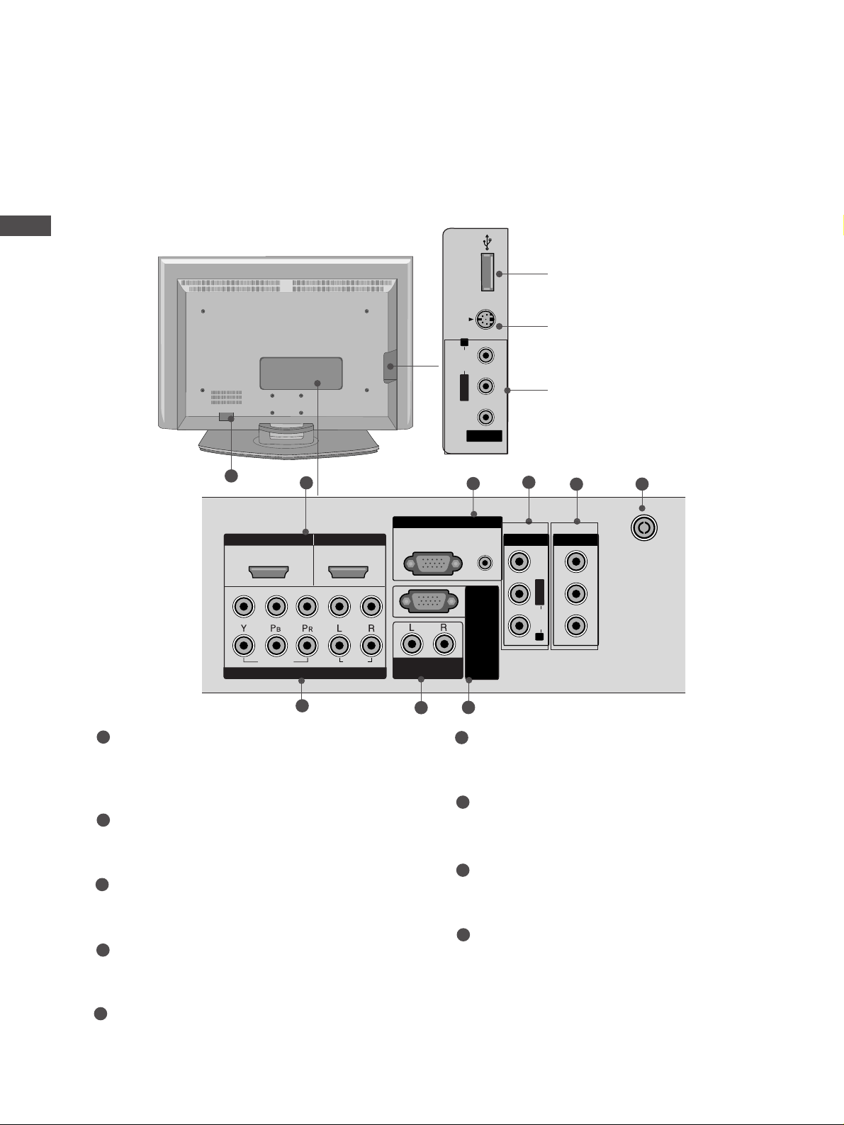
PREPARATION
PREPARATION
USB IN
AV IN 2
L/ MONO
R
AUDIO
VIDEO
S-VIDEO
LCD TV Models
8
USB Input
S-Video Input
Connect S-Video out from an SVIDEO device.
Audio/Video Input
Connect audio/video output from
an external device to these jacks.
USB INUSB IN
AV IN 2V IN 2
L/MONOMONO
R
AUDIOAUDIO
VIDEOVIDEO
S-VIDEOS-VIDEO
USB IN
AV IN 2
L/ MONO
R
AUDIO
VIDEO
S-VIDEO
HDMI IN
HDMI/D
VI IN
ARIABLE
UDIO OUT
COMPONENT IN
V IN 1
V OUT
RGB IN
(CONTR
L/
MONO
AUDIO
VIDEO
2
1
4
3
5
7
6
9
HDMI/DVI1, HDMI2 Input
Connect a HDMI signal to HDMI IN.
Or DVI(VIDEO)signal to HDMI/DVI port with DVI
to HDMI cable.
RGB/Audio Input
Connect the monitor output from a PC to the
appropriate input port.
Audio/Video Input (AV IN 1)
Connect audio/video output from an external
device to these jacks.
AV Output
Connect second TV or monitor to the AV OUT
socket on the TV.
Antenna Input
Connect RF antenna (UHF) to this jack
Component Input 1/2
Connect a component video/audio device to
these jacks.
Variable Audio Output
Connect an external amplifier or add a subwoofer
to your surround sound system.
RS-232C Input
(CONTROL&SERVICE)Port
Connect the serial port of the control devices
to the RS-232C jack.
Power Cord Socket
This TV operates on an AC power. The voltage is
indicated on the Specifications page. Never
attempt to operate the TV on DC power.
1
2
3
4
5
6
7
8
9
1
2
HDMI/D
VI IN
1
VIDEO
COMPONENT IN
HDMI IN
2
AUDIO
RGB IN
RGB(PC)
VARIABLE
AUDIO OUT
OL&SERVICE)
NTR
(CO
AV IN 1
AV OUT
VIDEO
MONO
L/
AUDIO
R
ANTENNA
IN
AUDIO
(RGB/DVI)
RS-232C IN

9
STAND INSTALLATION (Only 32, 37 inch LCD TV Models)
PREPARATION
1
2
3
Carefully place the TV screen side down on a
cushioned surface to protect the screen from
damage.
Assemble the TV as shown.
Fix the 4 bolts securely using the holes in the
back of the TV.
10
ATTACHING THE TV TO A WALL(This feature is not available for all models.)
PREPARATION
PREPARATION
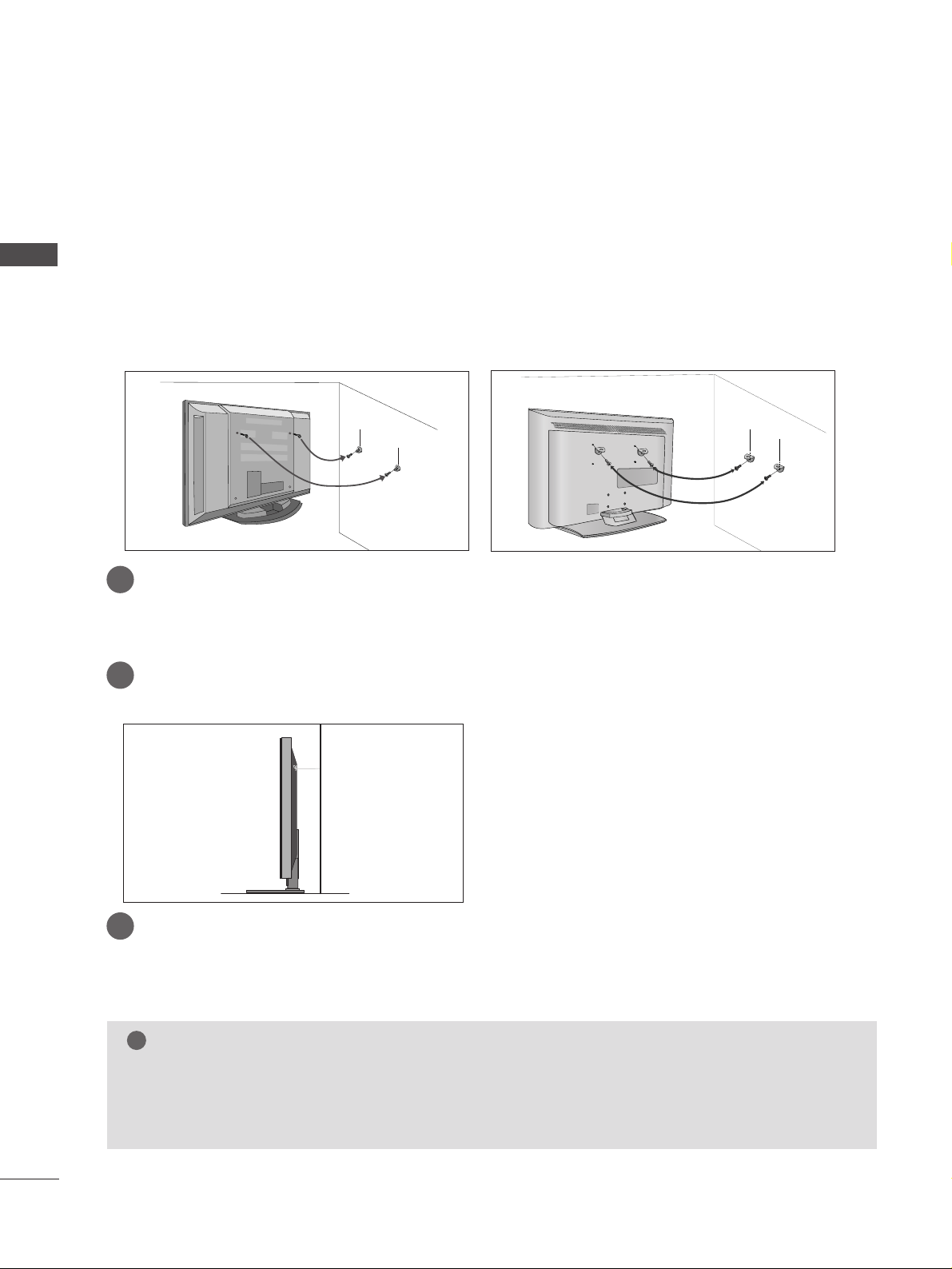
Plasma TV models LCD TV models
2
1
A
Position the TV close to the wall to avoid the possibility of it falling when pushed.
A
The instructions shown below are a safer way to set up the TV, which is to fix it to the wall, avoiding the
possibility of it falling forwards if pulled. This will prevent the TV from falling forward and causing injury.
This will also prevent the TV from damage. Ensure that children do not climb or hang from the TV.
NOTE
!
G
When moving the TV undo the cords first.
G
Use a platform or cabinet string and large enough to support the size and weight of the TV.
G
To use the TV safely make sure that the height of the bracket on the wall and on the TV is the same.
2
3
1
1
2
Use the eye-bolts or TV brackets/bolts to fix the product to the wall as shown in the picture.
(If your TV has bolts in the eyebolts, loosen then bolts.)
* Insert the eye-bolts or TV brackets/bolts and tighten them securely in the upper holes.
Secure the wall brackets with bolts (must purchase seperately) to the wall.
Ensure that both brackets are even.
3
Use a strong cord (must purchase separately) to secure the TV.
Secure the cord in such a way that it becomes taught when the TV is in position.
11
BACK COVER FOR WIRE ARRANGEMENT
PREPARATION
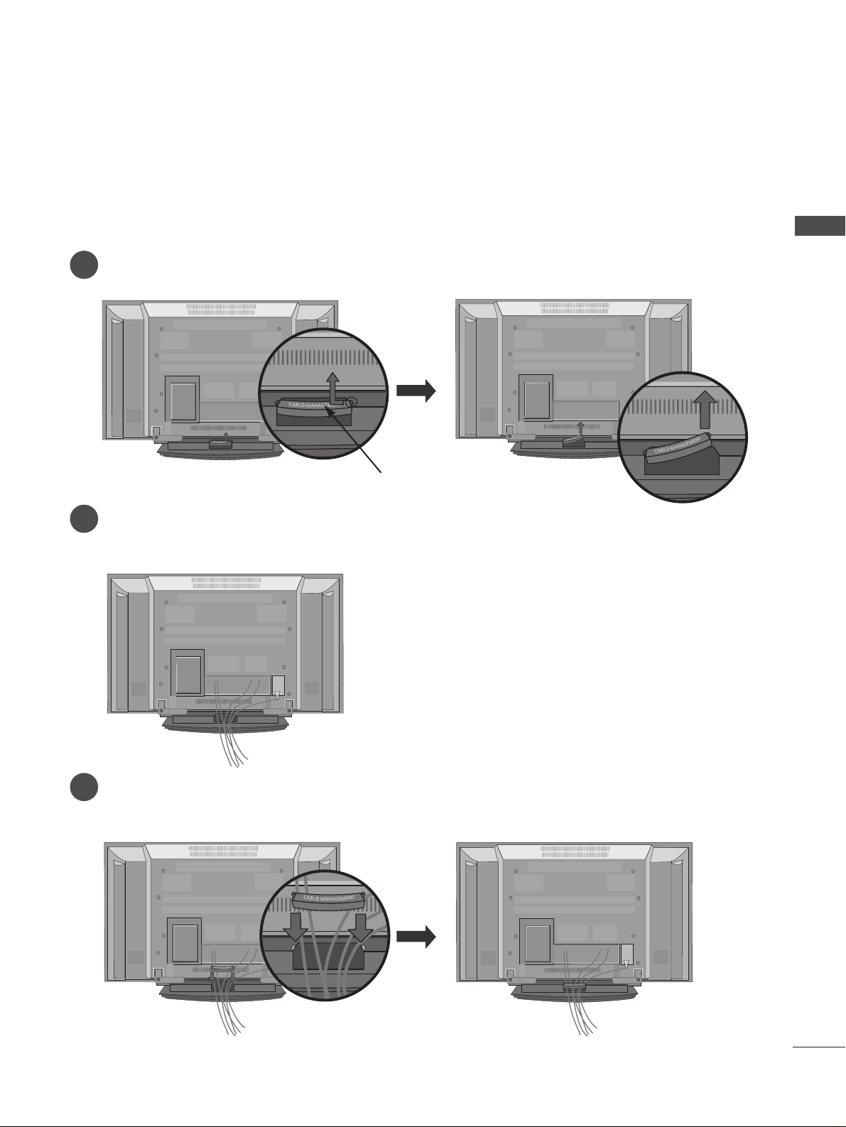
Plasma TV models
Connect the cables as necessary.
To connect additional equipment, see the
EExxtteerrnnaall eeqquuiippmmeenntt SS eettuupp
section.
Reinstall the
CC AABBLLEE MMAA NNAAGGEE MMEE NNTT
as shown
2
1
3
Grip the
CC AABBLLEE MMAA NNAAGGEE MMEE NNTT
and push the cover upwards
CABLE MANAGEMENT
12
PREPARATION
PREPARATION
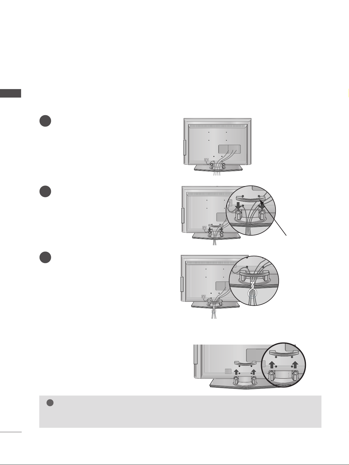
LCD TV models
Connect the cables as necessary.
To connect additional equipment, see the
EExxtteerrnnaall eeqquuiippmmeenntt SS eettuupp
section.
1
Reinstall the
CC AABBLLEE MMAA NNAAGGEE MMEE NNTT
as
shown
2
Bundle the cables together using the supplied
twister holder. (This feature is not available for
all models.)
3
Hold the
CC AABBLLEE MMAANN AAGGEEMMEE NNTT
with both
hands and pull it upward.
NOTE
!
GG
Do not use the CABLE MANAGEMENT to lift the TV.
- If the TV is dropped, you may be injured or the TV may be damaged.
How to remove the cable management
CABLE MANAGEMENT

13
■
The TV can be installed in various ways such as on a wall, or on a desktop etc.
■
The TV is designed to be mounted horizontally.
PREPARATION
WALL MOUNT: HORIZONTAL INSTALLATION
For adequate ventilation allow a clearance of 4” (10cm) all around the TV. Detailed installation instruc-tions
are available from your dealer, see the optional Tilt Wall Mounting Bracket Installation and Setup Guide.
4 inches
4 inches
4 inches
4 inches
4 inches
Power Supply
Circuit breaker
EARTHING
Ensure that you connect the earth wire to prevent possible
electric shock. If grounding methods are not possible, have a
qualified electrician install a separate circuit breaker.
Do not try to earth the TV by connecting it to telephone
wires, lightening rods or gas pipes.
DESKTOP PEDESTAL INSTALLATION
For adequate ventilation allow a clearance of 4” (10cm) all around the TV .
4 inches
4 inches
4 inches
4 inches
R
USB
AV IN 2
L/MONO
R
AUDIO
S-VIDEO
14
PREPARATION
PREPARATION
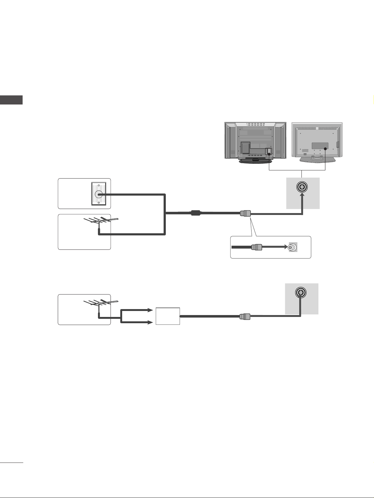
ANTENNA CONNECTION
■
It is recommended that 42PB4RTH / 50PB4RTH model only be used at an altitude of less than 6561 feet
(2000m) to get the best quality picture and sound.
■
To prevent damage do not connect to the mains outlet until all connections are made between the devices.
USB IN
AV IN 2
L/MONO
R
AUDIO
VIDEO
S-VIDEO
■
For optimum picture quality, adjust antenna direction.
■
An antenna cable and converter are not supplied.
Multi-family Dwellings/Apartments
(Connect to wall antenna socket)
Single-family Dwellings /Houses
(Connect to wall jack for outdoor antenna)
Outdoor
Antenna
Wall
Antenna
Socket
RF Coaxial Wire (75 ohm)
Antenna
UHF
Signal
Amplifier
VHF
■
In poor signal areas, to achieve better picture quality it may be necessary to install a signal amplifier to the
antenna as shown above.
■
If signal needs to be split for two TVs,use an antenna signal splitter for connection.
ANTENNA
IN
ANTENNA
IN
15
HD RECEIVER SETUP
EXTERNAL EQUIPMENT SETUP
EXTERNAL EQUIPMENT SETUP
1
1
2
2
VAAUVA
AU
COMPONENT INCOMPONENT IN
AUDIO
VIDEO
1
2
COMPONENT IN
AUDIO
VIDEO
HDMI/DVI IN
1
1 2
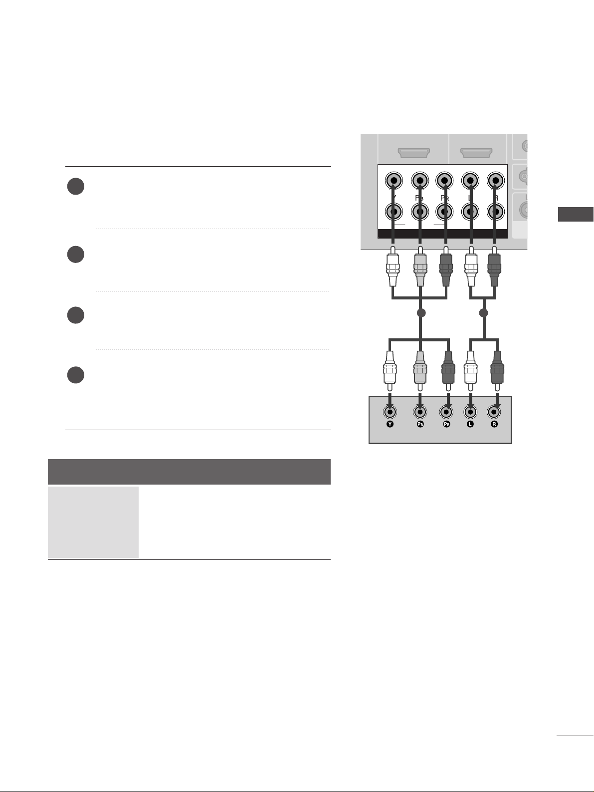
Connecting with a component cable
Connect the video outputs (Y, PB
, PR
)
of the digital set
top box to the
CC OOMMPPOO NNEENNTT IINN VVIIDDEE OO
jacks on the
TV.
Connect the audio output of the digital set-top box to
the
CC OOMMPPOO NNEENNTT IINN AAUU DDIIOO
jacks on the TV.
Turn on the digital set-top box.
(
Refer to the owner’s manual for the digital set-top box.
)
Select
Component1 input source using the
II NNPPUUTT
button on the remote control.
If connected to
CC OOMMPPOO NNEENNTT II NN22
, select
Component2 input source.
2
3
4
1
Signal
480i/576i
480p/576p
720p/1080i
1080p(50/60Hz)
Component 1/2
Yes
Yes
Yes
Yes
HDMI1/DVI, HDMI2
No
Yes
Yes
Yes
■
To avoid damaging any equipment, never plug in any power cords until you have finished connecting all equipment.
■
This section on EXTERNAL EQUIPMENT SETUP mainly uses diagrams for the LCD TV models.
16
EXTERNAL EQUIPMENT SETUP
EXTERNAL EQUIPMENT SETUP
HDMI IN HDMI IN HDMI/DVI IN HDMI/DVI IN
1
1
2
2
COMPONENT INCOMPONENT IN
AUDIO
VIDEO
HDMI IN HDMI/DVI IN
1 2
1
2
COMPONENT IN
HDMI-DTV OUTPUT
HDMI/DVI IN
1
1
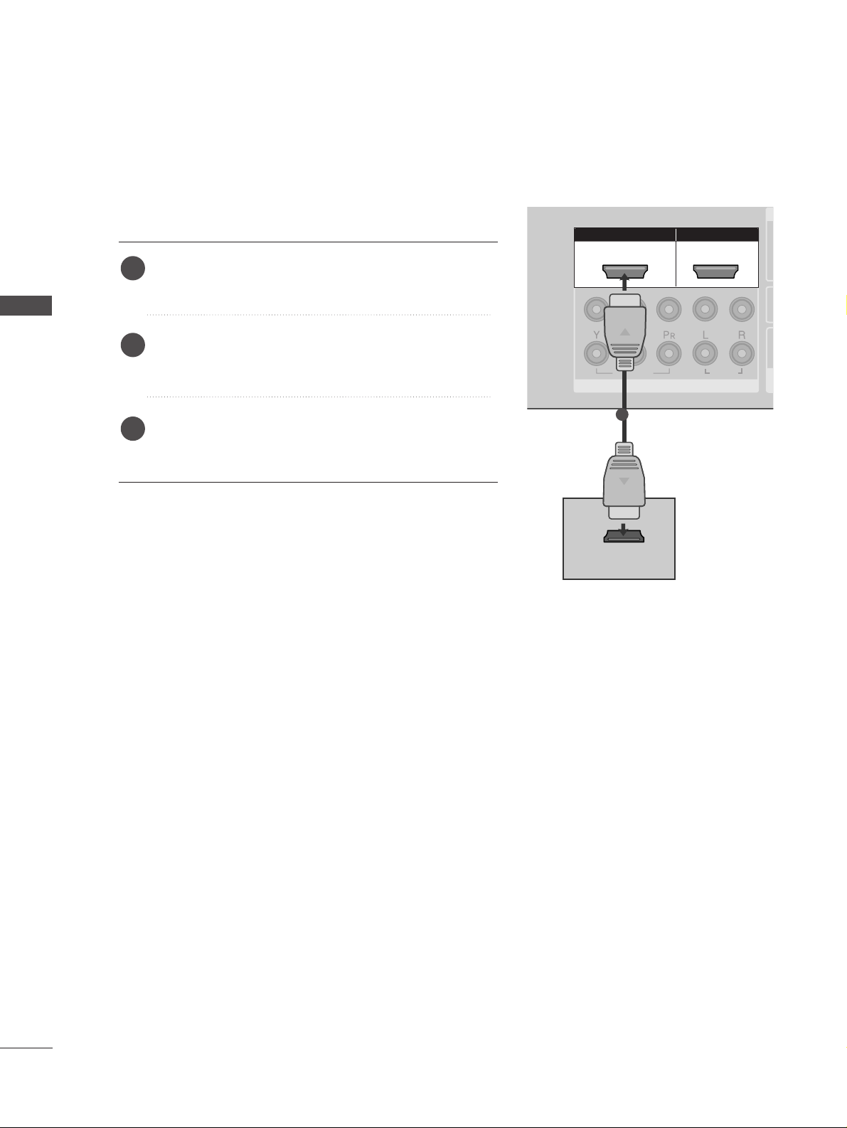
Connecting with a HDMI cable
Connect the HDMI output of the digital set-top box to
the
HHDD MMII//DDVVII IINN 11
or
HHDDMMII IINN 22
jack on the TV.
Select
HDMI1/DVI or HDMI2 input source using the
II NNPPUUTT
button on the remote control.
Turn on the digital set-top box.
(
Refer to the owner’s manual for the digital set-top box.
)
2
3
1
17
EXTERNAL EQUIPMENT SETUP
HDMI IN HDMI IN HDMI/DVI IN HDMI/DVI IN
1
1
2
2
VARIABLE
AUDIO OUT
VARIABLE
AUDIO OUT
COMPONENT INCOMPONENT IN
AUDIO
VIDEO
AV IN 1AV IN 1 AV OUTAV OUT
ANTENNA
IN
ANTENNA
IN
AUDIO
(RGB/DVI)
RGB(PC)
RGB INRGB IN
RS-232C IN
(CONTROL&SERVICE)
RS-232C IN
(CONTROL&SERVICE)
L/MONO
R
AUDIO
VIDEO
RGB(PC)
HDMI/DVI IN
1
AUDIO
(RGB/DVI)
RGB IN
1
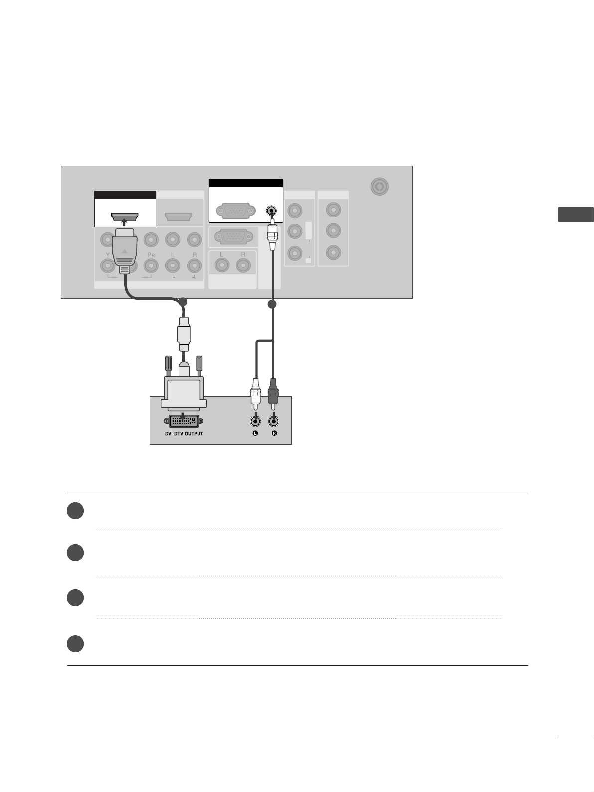
2
Connect the DVI output of the digital set-top box to the
HHDD MMII//DDVVII IINN 11
jack on the TV.
Connect the audio output of the digital set-top box to the
AAUUDDIIOO((RRGG BB//DDVVII))
jack on the TV.
Turn on the digital set-top box. (Refer to the owner’s manual for the digital set-top box.
)
Select
HDMI1/DVI input source using the
II NNPPUUTT
button on the remote control.
2
3
4
1
Connecting with a HDMI to DVI cable
18
DVD SETUP
EXTERNAL EQUIPMENT SETUP
EXTERNAL EQUIPMENT SETUP
USB IN
AV IN 2
L/ MONO
R
AUDIO
VIDEO
S-VIDEO
1
2
VAV
A
COMPONENT INCOMPONENT IN
AUDIO
VIDEO
1
2
COMPONENT IN
AUDIO
VIDEO
1 2
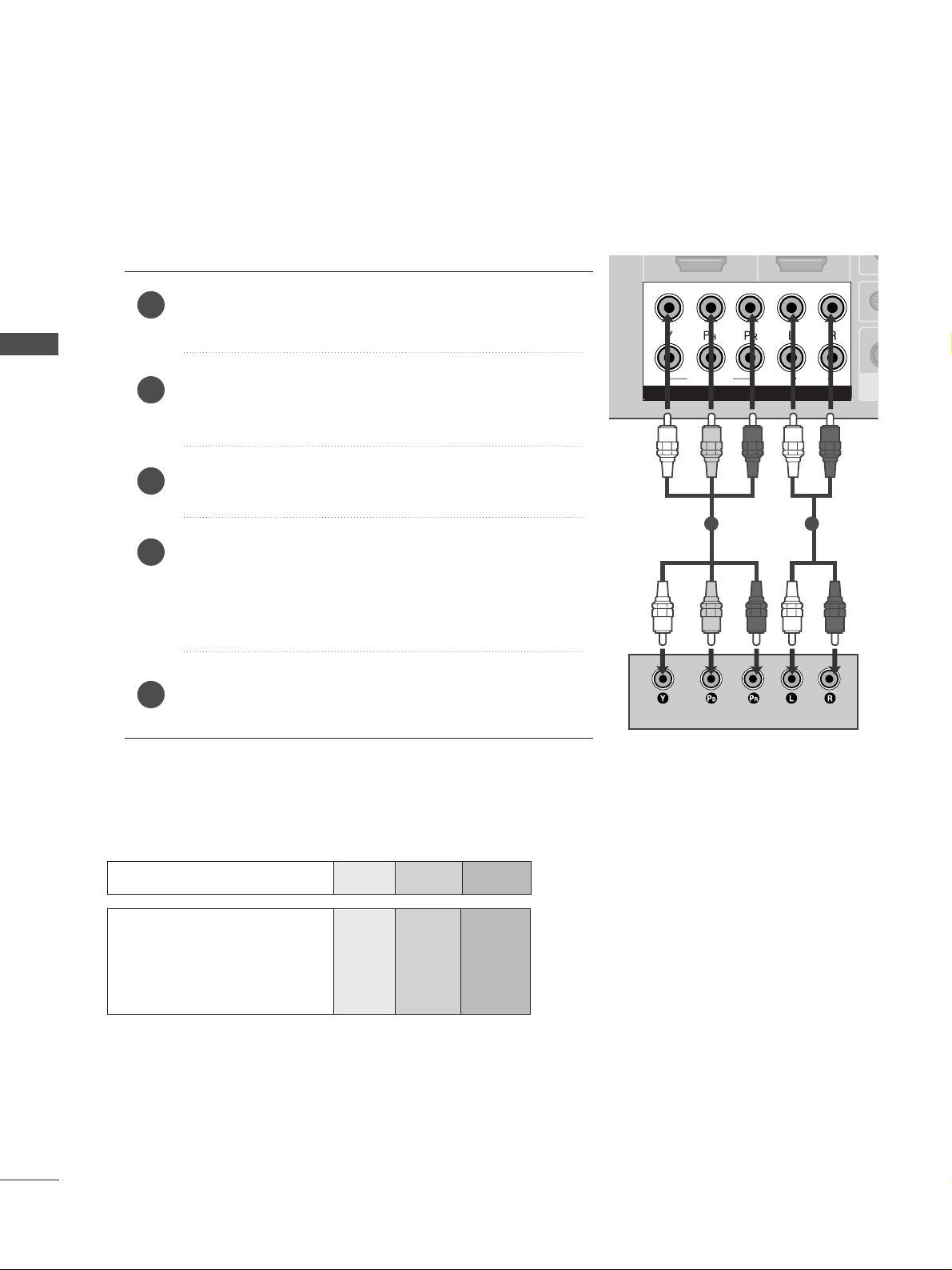
Connecting with a component cable
Component Input ports
To achieve better picture quality, connect a DVD player to the component input ports as shown below.
Component ports on the TV
YPBP
R
Video output ports
on DVD player
Y
Y
Y
Y
P
B
B-Y
Cb
Pb
P
R
R-Y
Cr
Pr
Connect the video outputs (Y, PB
, PR
)
of the DVD to the
CC OOMMPPOO NNEENNTT IINN VVIIDDEE OO
jacks on the TV.
Connect the audio outputs of the DVD to the
CC OOMM PPOO--
NNEENNTT II NN AAUUDDIIOO
jacks on the TV.
Turn on the DVD player, insert a DVD.
Select
Component
11
input source using the
II NNPPUUTT
but-
ton on the remote control.
If connected to
CC OOMMPPOO NNEENNTT II NN22
, select
Component2
input source.
Refer to the DVD player's manual for operating instructions.
2
3
4
5
1
19
EXTERNAL EQUIPMENT SETUP
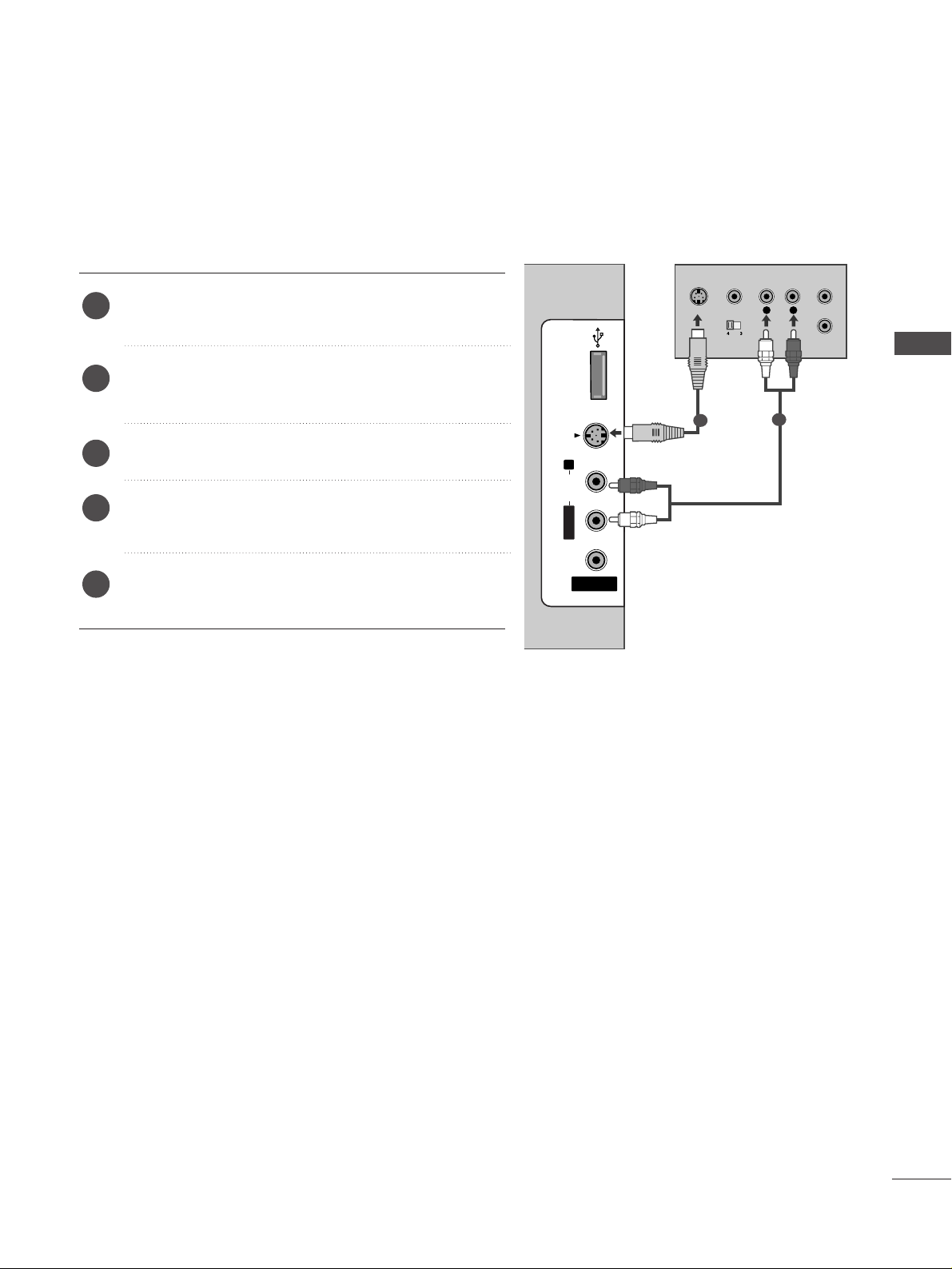
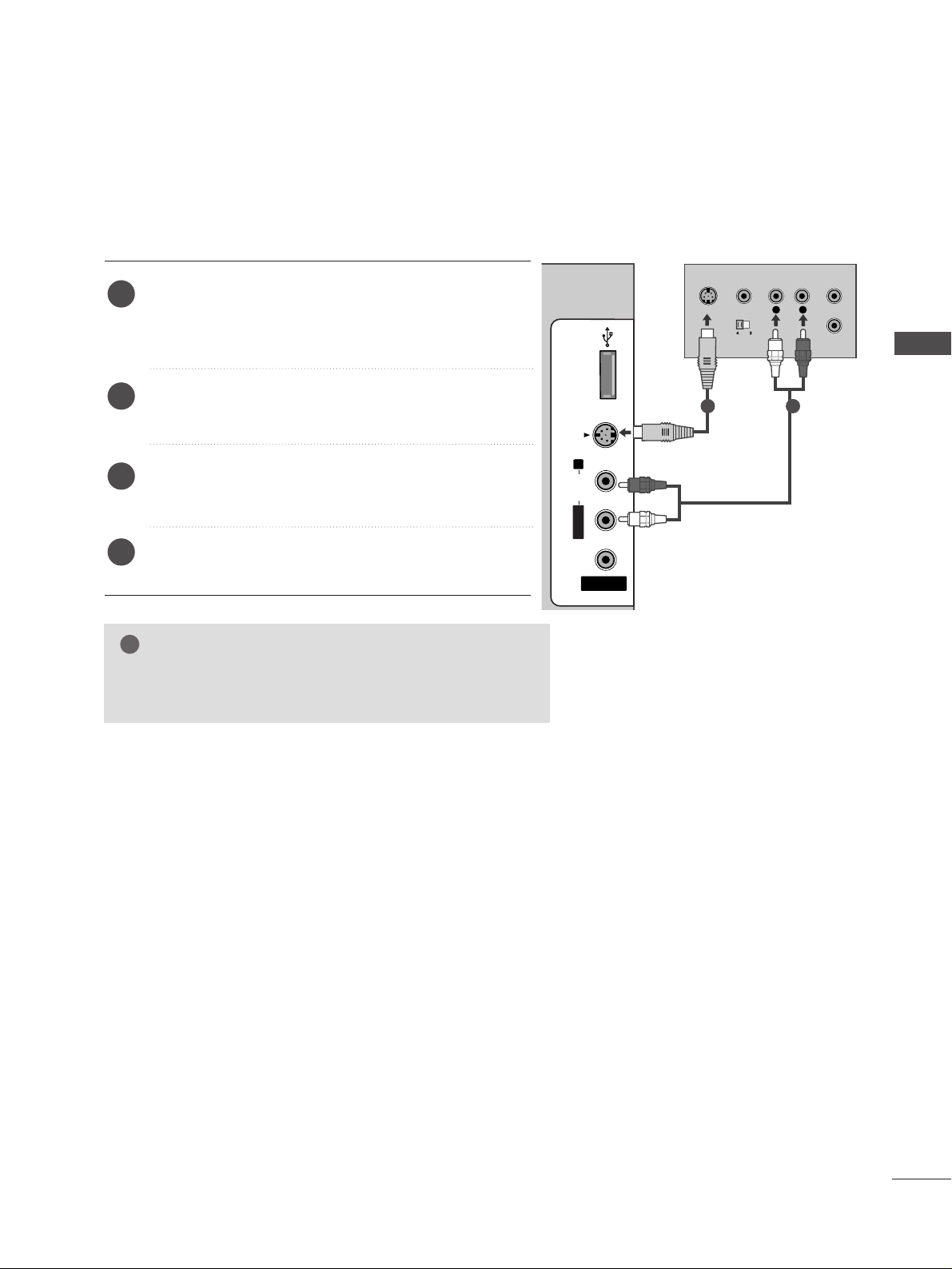
Connecting with an S-Video cable
Connect the S-VIDEO output of the DVD to the
SS--
VVIIDDEEOO
input on the TV.
Connect the audio outputs of the DVD to the
AAUUDDIIOO
input jacks on the TV.
Turn on the DVD player, insert a DVD.
Select
AV 2 input source using the
II NNPPUUTT
button on
the remote control.
Refer to the DVD player's manual for operating
instructions.
2
3
4
5
1
USB INUSB IN
AV IN 2
L/MONO
R
AUDIOAUDIO
VIDEOVIDEO
S-VIDEOS-VIDEO
L
R
S-VIDEO
VIDEO
OUTPUT
SWITCH
ANT IN
ANT OUT
1
2
20
EXTERNAL EQUIPMENT SETUP
EXTERNAL EQUIPMENT SETUP
HDMI IN HDMI IN HDMI/DVI IN HDMI/DVI IN
1
1
2
2
VAV
A
COMPONENT INCOMPONENT IN
AUDIO
VIDEO
HDMI IN HDMI/DVI IN
1 2
HDMI-DTV OUTPUT
USB IN
AV IN 2
L/ MONO
R
AUDIO
VIDEO
S-VIDEO
1
2
COMPONENT IN
1
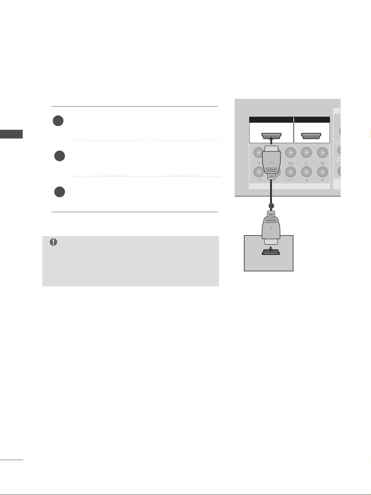
Connecting the HDMI cable
Connect the HDMI output of the DVD to the
HHDD MMII//DDVVII IINN 11
or
HHDDMMII IINN 22
jack on the TV.
Select
HDMI1/DVI or HDMI2 input source using
the
II NNPPUUTT
button on the remote control.
Refer to the DVD player's manual for operating
instructions.
1
2
3
GG
TV can receive the video and audio signal simultaneously
with using a HDMI cable.
GG
If the DVD player does not support Auto HDMI, you must
set the output resolution appropriately.
NOTE
21
VCR SETUP
EXTERNAL EQUIPMENT SETUP
AV IN 1AV IN 1 AV OUTAV OUT
AUDIO
(RGB/DVI)
RGB INRGB IN
RS-232C IN
(CONTROL&SERVICE)
RS-232C IN
(CONTROL&SERVICE)
L/ MONO
R
AUDIO
VIDEO
ANTENNA
IN
OUTPUT
SWITCH
ANT IN
R
S-VIDEO VIDEO
ANT OUT
L
Wall Jack
Antenna
1
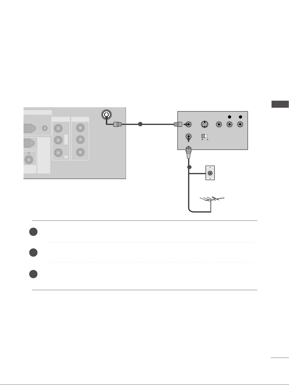
Connecting with a RF Cable
■
To avoid picture noise (interference), allow adequate distance between the VCR and TV.
■
Typically a frozen still picture from a VCR. If 4:3 picture format is used for an extended period the fixed
images on the sides of the screen may remain visible.
Connect the
AANN TT OOUU TT
socket of the VCR to the
AANN TTEENN NNAA IINN
socket on the TV.
Connect the antenna cable to the
AANN TT IINN
socket of the VCR.
Press the
PPLLAAYY
button on the VCR and match the appropriate programme between the TV and VCR for
viewing.
1
2
2
3
1
22
EXTERNAL EQUIPMENT SETUP
EXTERNAL EQUIPMENT SETUP
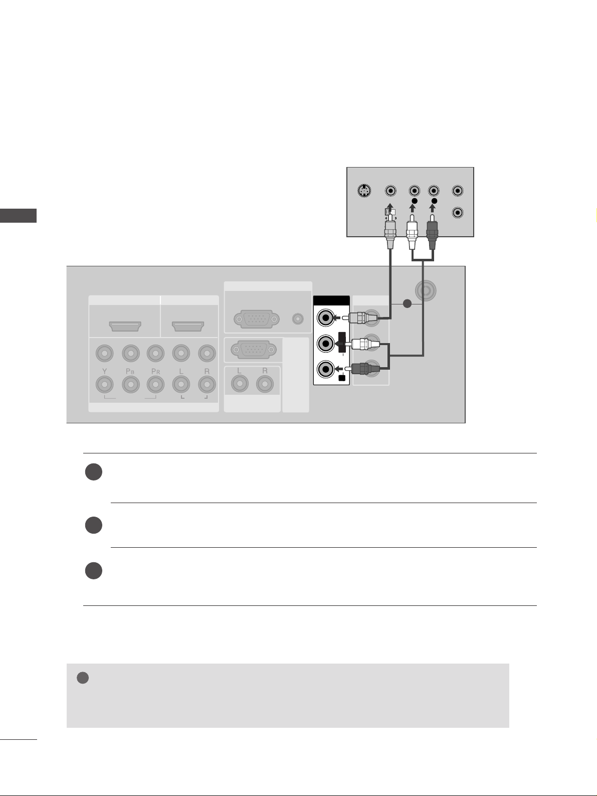
Connecting with a RCA cable
HDMI IN HDMI IN HDMI/DVI IN HDMI/DVI IN
1
1
2
2
VARIABLE
AUDIO OUT
VARIABLE
AUDIO OUT
COMPONENT INCOMPONENT IN
AUDIO
VIDEO
AV IN 1AV IN 1 AV OUTAV OUT
ANTENNA
IN
ANTENNA
IN
AUDIO
(RGB/DVI)
RGB(PC)
RGB INRGB IN
RS-232C IN
(CONTROL&SERVICE)
RS-232C IN
(CONTROL&SERVICE)
L/ MONO
R
AUDIO
VIDEO
AV IN 1V IN 1
L/L/MONOMONO
R
AUDIOAUDIO
VIDEOVIDEO
L
R
S-VIDEO
VIDEO
OUTPUT
SWITCH
ANT IN
ANT OUT
Connect the
AAUUDDIIOO/VVIIDDEEOO
jacks between TV and VCR. Match the jack colours (Video = yellow,
Audio Left = white, and Audio Right = red)
Insert a video tape into the VCR and press PLAY on the VCR. (Refer to the VCR owner’s manual.
)
Select
AV 1 input source using the
II NNPPUUTT
button on the remote control.
If connected to
AAVV II NN22
, select
AV 2 input source.
1
2
3
GG
If you have a mono VCR, connect the audio cable from the VCR to the
AAUUDDIIOO LL//MMOO NNOO
jack
of the TV.
NOTE
!
1
EXTERNAL EQUIPMENT SETUP
23
GG
If both S-VIDEO and VIDEO sockets have been connected to
the S-VHS VCR simultaneously, only the S-VIDEO can be
received.
NOTE
!
USB INUSB IN
AV IN 2
L/MONO
R
AUDIOAUDIO
VIDEOVIDEO
S-VIDEOS-VIDEO
L
R
S-VIDEO
VIDEO
OUTPUT
SWITCH
ANT IN
ANT OUT
Connecting with a S-Video cable
Connect the S-VIDEO output of the VCR to the S
--
VV II DDEE OO
input on the TV. The picture quality is
improved; compared to normal composite (RCA cable)
input.
Connect the audio outputs of the VCR to the AUDIO
input jacks on the TV.
Insert a video tape into the VCR and press PLAY on
the VCR. (Refer to the VCR owner’s manual.)
Select
AV 2 input source using the
II NNPPUUTT
button on
the remote control.
2
3
4
1
1 2
24
OTHER A/V SOURCE SETUP
EXTERNAL EQUIPMENT SETUP
EXTERNAL EQUIPMENT SETUP
USB INUSB IN
AV IN 2
L/MONO
R
AUDIOAUDIO
VIDEOVIDEO
S-VIDEOS-VIDEO
L R
VIDEO
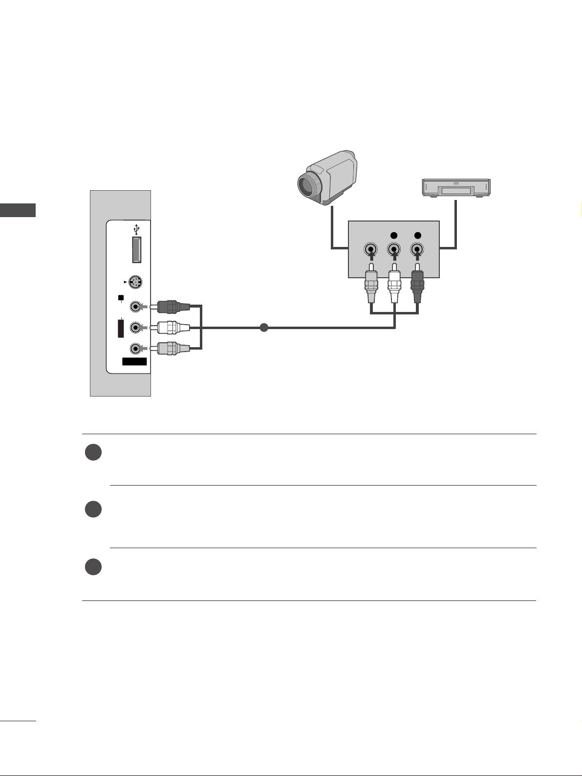
Camcorder
Video Game Set
1
Connect the
AAUUDDIIOO/VVIIDDEEOO
jacks between TV and external equipment. Match the jack colours
.
(
Video = yellow, Audio Left = white, and Audio Right = red
)
Select AV 2 input source with using the
II NNPPUUTT
button on the remote control.
If connected to
AAVV II NN11
, select
AV 1 input source.
Operate the corresponding external equipment.
Refer to external equipment operating guide.
1
2
3
EXTERNAL EQUIPMENT SETUP
25
AV OUTPUT SETUP
EXTERNAL STEREO SETUP
AV OUT
VARIABLE
AUDIO OUT
VARIABLE
AUDIO OUT
AUDIO
RS-232C IN
(CONTROL&SER
RS-232C IN
(CONTROL&SER
R
AUDI
VARIABLE
AUDIO OUT
GG
When connecting with external audio equipments, such as
amplifiers or speakers, please turn the TV speakers off.
(
GG
pp..9966
)
NOTE
!
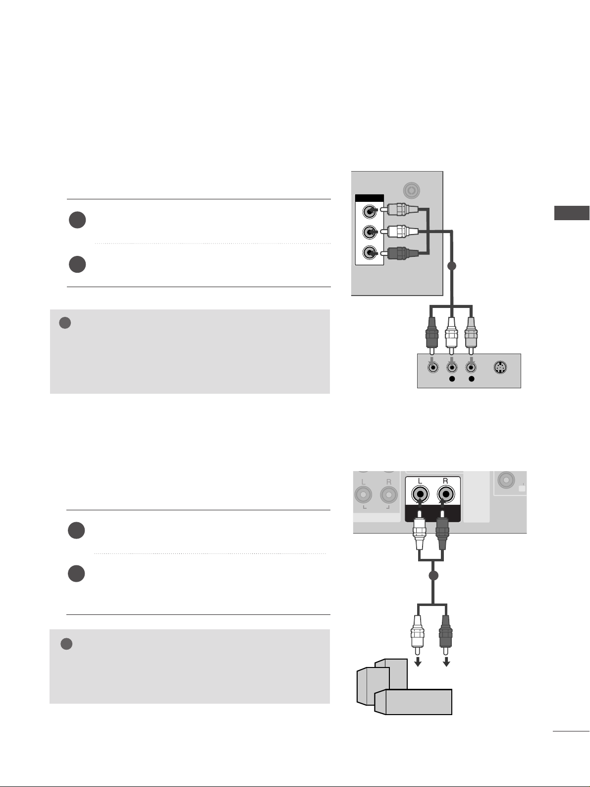
Use to connected either an external amplifier, or add a subwoofer to your surround sound system.
Connect the input jack of the stereo amplifier to the
VVAARRIIAA BBLLEE AA UUDD II OO OOUUTT
jacks on the TV.
Set up your speakers through your analog stereo
amplifier, according to the instructions provided with
the amplifier.
2
1
11
The TV has a special signal output capability which allows you to hook up the second TV or monitor.
AV OUTAV OUT
ANTENNA
IN
ANTENNA
IN
AV OUTV OUT
L R
S-VIDEOVIDEO
Connect the second TV or monitor to the TV’s
AAVV OOUUTT
jacks.
See the Operating Manual of the second TV or monitor
for further details regarding that device’s input settings.
GG
Component, RGB, HDMI input sources cannot be used for
AV out.
GG
We recommend to use the AV OUT jacks for VCR recording.
NOTE
!
2
1
1
26
USB IN SETUP
EXTERNAL EQUIPMENT SETUP
EXTERNAL EQUIPMENT SETUP
USB INUSB IN
AV IN 2
L/L/MONOMONO
R
AUDIOAUDIO
VIDEOVIDEO
S-VIDEOS-VIDEO
or
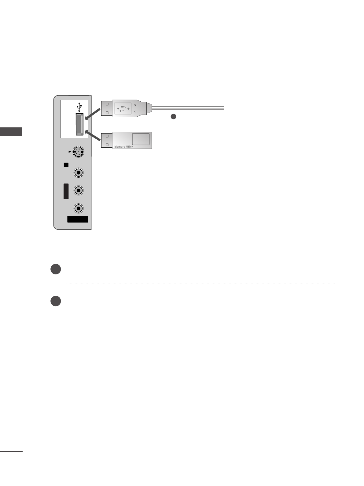
Connect the USB device to the
UUSSBB IINN
jacks on the side of TV.
After connecting the
UUSSBB IINN
jacks, you use the
TTIIMMEE MMAACCHH II NNEE
function. (
GG
pp..5588
)
2
1
1
27
PC SETUP
EXTERNAL EQUIPMENT SETUP
HDMI IN HDMI IN HDMI/DVI IN HDMI/DVI IN
1
1
2
2
VARIABLE
AUDIO OUT
VARIABLE
AUDIO OUT
COMPONENT INCOMPONENT IN
AUDIO
VIDEO
AV IN 1AV IN 1 AV OUTAV OUT
ANTENNA
IN
ANTENNA
IN
AUDIO
(RGB/DVI)
RGB(PC)
RGB INRGB IN
RS-232C IN
(CO
NTROL&SERVICE)
RS-232C IN
(CO
NTROL&SERVICE)
L/M
O
NO
R
A
U
D
IO
V
ID
E
O
AUDIO
(RGB/DVI)
RGB(PC)
RGB INRGB IN
RGB OUTPUT
AUDIO
1
2
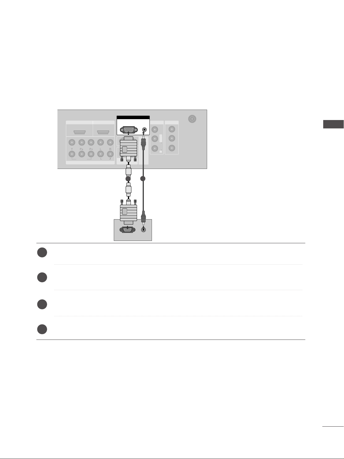
This TV provides Plug and Play capability, meaning that the PC adjusts automatically to the TV's settings.
Connecting with a D-sub 15 pin cable
Connect the RGB output of the PC to the
RRGGBB ((PPCC))
jack on the TV.
Connect the PC audio output to the
AAUUDDIIOO((RRGG BB//DDVVII))
jack on the TV.
Turn on the PC and the TV.
Select
RGB input source using the
II NNPPUUTT
button on the remote control.
2
3
4
1

EXTERNAL EQUIPMENT SETUP
28
EXTERNAL EQUIPMENT SETUP
Connecting with a HDMI to DVI cable
RGB IN
HDMI IN HDMI IN HDMI/DVI IN HDMI/DVI IN
1
1
2
2
VARIABLE
AUDIO OUT
VARIABLE
AUDIO OUT
COMPONENT INCOMPONENT IN
AUDIO
VIDEO
AV IN 1AV IN 1 AV OUTAV OUT
ANTENNA
IN
ANTENNA
IN
AUDIO
(RGB/DVI)
RGB(PC)
RGB INRGB IN
RS-232C IN
(CO
NTRO
L&SERVICE)
RS-232C IN
(CO
NTRO
L&SERVICE)
L/ MONO
R
AUDIO
VIDEO
RGB(PC)
HDMI/DVI IN
1
AUDIO
(RGB/DVI)
RGB IN
DVI-PC OUTPUT
AUDIO
1
2
Connect the DVI output of the PC to the
HHDD MMII//DDVVII IINN 11
jack on the TV.
Connect the PC audio output to the
AAUUDDIIOO((RRGG BB//DDVVII))
jack on the TV.
Turn on the PC and the TV.
Select
HDMI1/DVI input source using the
II NNPPUUTT
button on the remote control.
2
3
4
1
GG
If the PC has a DVI output and no HDMI output, a separated audio connection is necessary.
GG
If the PC does not support Auto DVI, you need to set the output resolution appropriately.
NOTE
!
 Loading...