How it Works
Log In / Sign Up
Buy Points
How it Works
FAQ
Contact Us
Questions and Suggestions
Users
LG
Loading...
#
47LA7400UDBUSYLJR
47LA7408
47LA7408-ZA
11
47LA7408-ZB
11
47LA740S
4
47LA740S-ZA
11
47LA740S-ZB
11
47LA740V
2
47LA740V-ZA
11
47LA740V-ZB
11
47LA7418-ZA
11
47LA741S-ZA
11
47LA741V
3
47LA741V-ZA
11
47LA741Y-TA
47LA7909
2
47LA7909-ZA
15
47LA790V
14
47LA790V-ZA
15
47LA790W
6
47LA790W-ZA
15
47LA86
47LA8600
11
47LA8609
2
47LA8609-ZA
14
47LA860T
47LA860V
12
47LA860V-ZA
14
47LA860W
3
47LA860W-ZA
14
47LA860Y
4
47LA860-Z
47LA868V
3
47LA868V-ZD
13
47LA9600-TA
47LA9609-ZA
14
47LA960V-ZA
14
47LA960W-ZA
14
47LA960Y-TA
47LA9650-TA
47LA965Y-TA
47LB1DA
8
47LB1DA 1080p LCD
47LB1DA-UB
47LB1R
47LB1RF
4
47LB2DE
2
47LB2R
10
47LB2RF
27
47LB2RF-ZH
47LB2R Series
2
47LB2R-ZH
47LB5600
47LB5600-SB
47LB5600-TA
47LB560B-TA
47LB560D-TA
47LB560T-TA
47LB560Y-TA
47LB560Z-TA
47LB5610
6
47LB5610-CD
47LB5610-SC
47LB5610-TC
2
47LB5610-ZC
6
47LB561B-TC
47LB561B-ZC
6
47LB561D-TC
47LB561T
3
47LB561T-TC
47LB561U-ZC
6
47LB561U-ZE
6
47LB561V
7
47LB561V-ZC
6
47LB561V-ZE
6
47LB561Y-TC
47LB561Z-TC
47LB5630-TD
47LB563B-TD
47LB563D-TD
47LB563T-TD
47LB563Y-TD
47LB563Z-TD
47LB5670-CR
47LB5690-CF
47LB569Y-TD
47LB569Z-TD
47LB57**
47LB5700
47LB5700-ZB
5
47LB5700-ZK
5
47LB570B-ZB
5
47LB570B-ZK
5
47LB570U-ZB
5
47LB570U-ZJ
5
47LB570U-ZK
5
47LB570V
4
47LB570V-ZB
5
47LB570V-ZF
5
47LB570V-ZJ
5
Loading...
Loading...
Nothing found
47LB2RF
Schematic
42 pgs
4.46 Mb
0
User Manual
80 pgs
2.3 Mb
0
User Manual
35 pgs
8.62 Mb
0
Owner’s Manual
87 pgs
1.91 Mb
0
User guide
88 pgs
2.34 Mb
0
Owner’s Manual [ar]
88 pgs
2.85 Mb
0
Owner’s Manual [ar]
88 pgs
3.37 Mb
0
Instruction book [da]
80 pgs
2.77 Mb
0
Owner’s Manual [de]
80 pgs
2.54 Mb
0
User Manual [de]
35 pgs
8.65 Mb
0
User manual [el]
80 pgs
3.34 Mb
0
User guide [es]
80 pgs
1.46 Mb
0
User Manual [es]
35 pgs
8.53 Mb
0
User Manual [es]
80 pgs
2.39 Mb
0
User manual [fi]
80 pgs
2.65 Mb
0
Owner’s Manual [fr]
88 pgs
1.87 Mb
0
User Manual [fr]
80 pgs
2.42 Mb
0
User guide [he]
176 pgs
3.95 Mb
0
User manual [hu]
80 pgs
2.38 Mb
0
User Manual [it]
80 pgs
2.36 Mb
0
User guide [lt]
80 pgs
1.54 Mb
0
User guide [lt,lv]
80 pgs
1.55 Mb
0
User Manual [nl]
80 pgs
2.3 Mb
0
User Manual [pl]
80 pgs
2.79 Mb
0
User Manual [pt]
80 pgs
2.56 Mb
0
User manual [sv]
80 pgs
2.43 Mb
0
User Manual [uk]
80 pgs
1.56 Mb
0
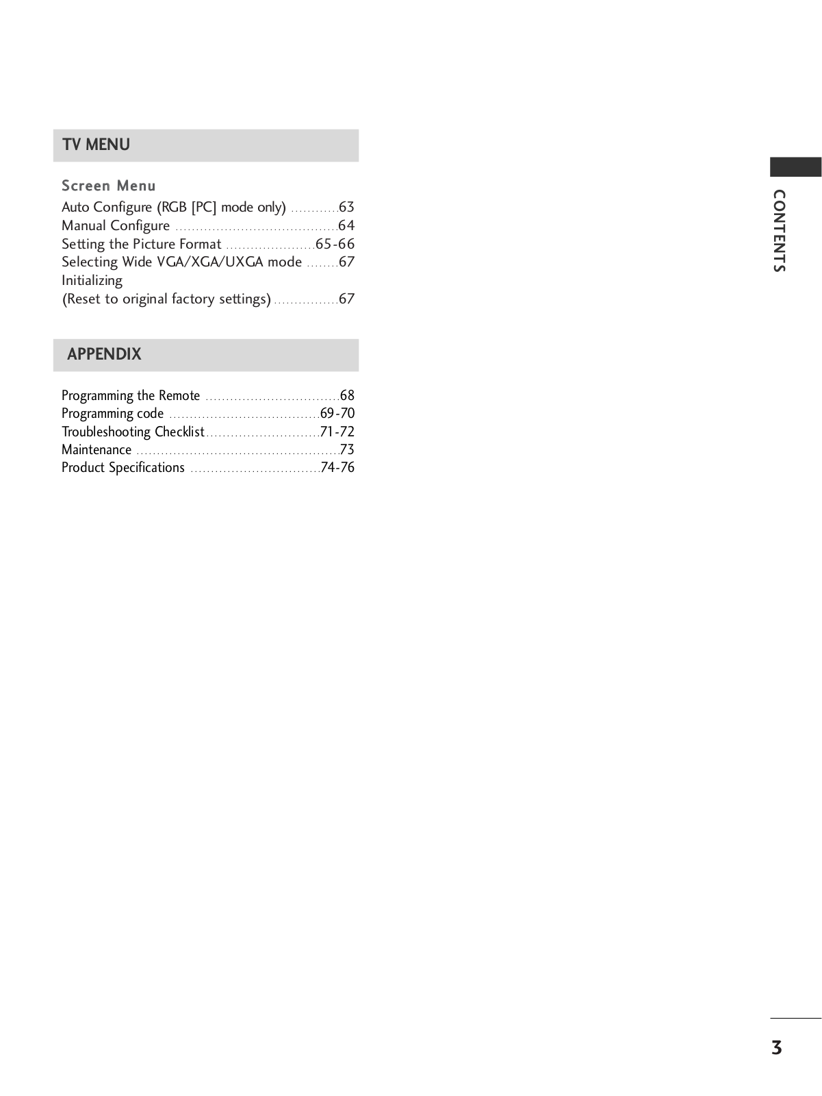
Table of contents
Loading...
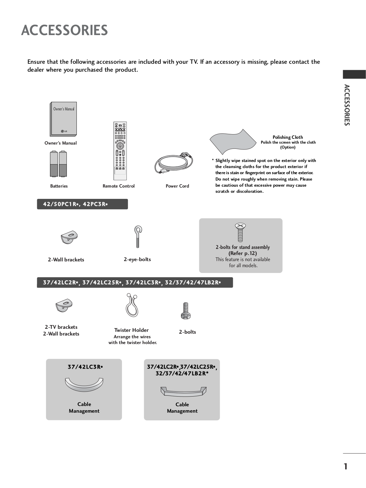
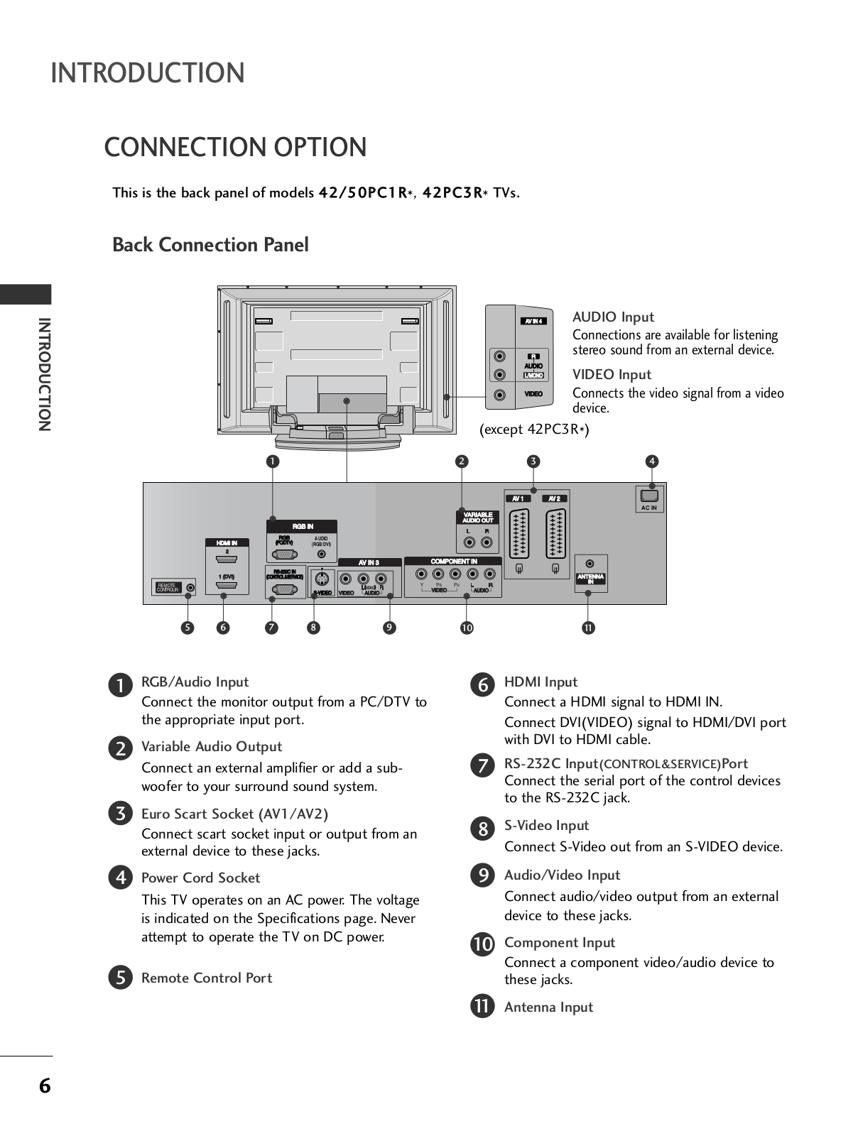
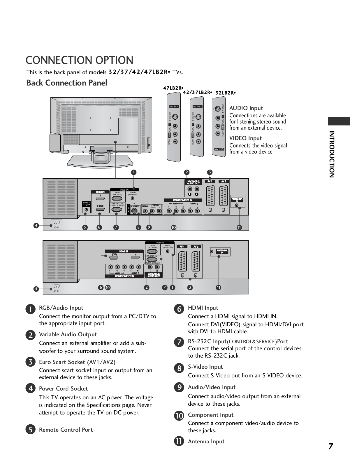
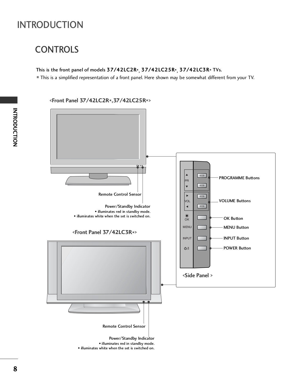
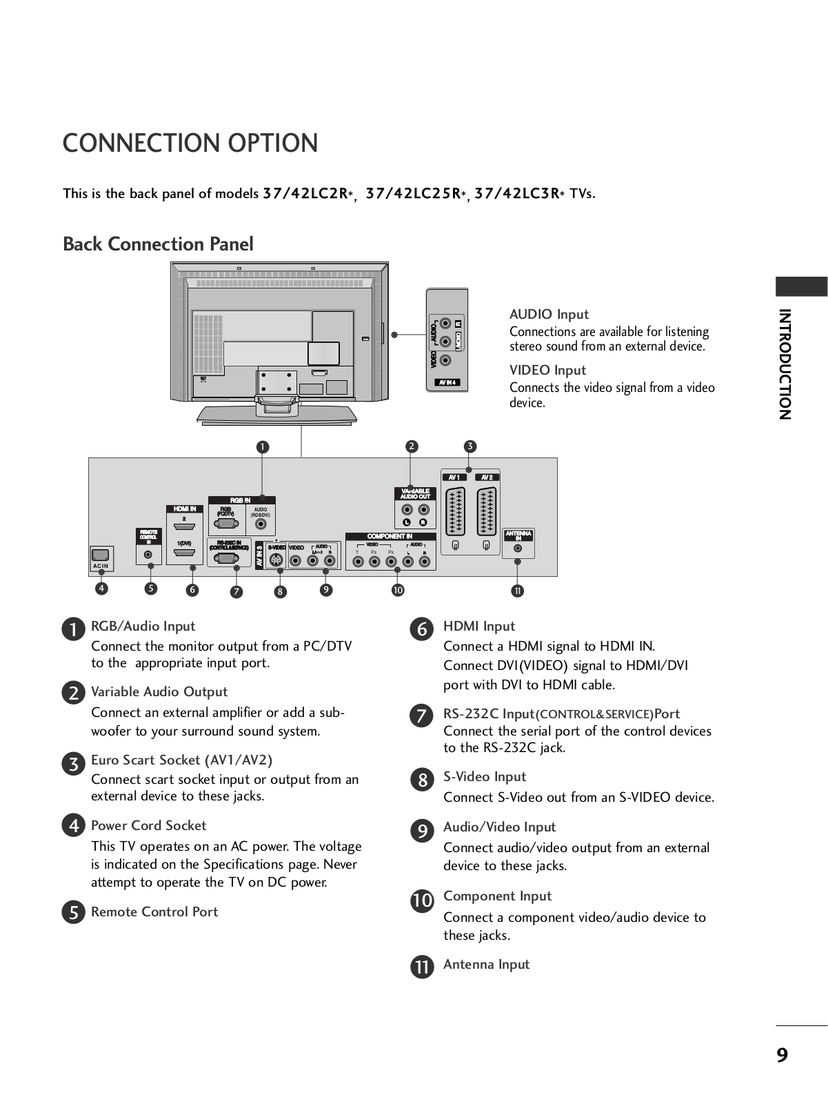
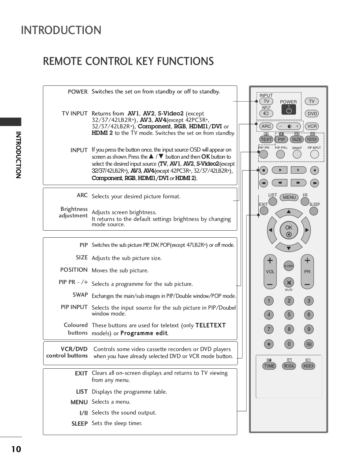
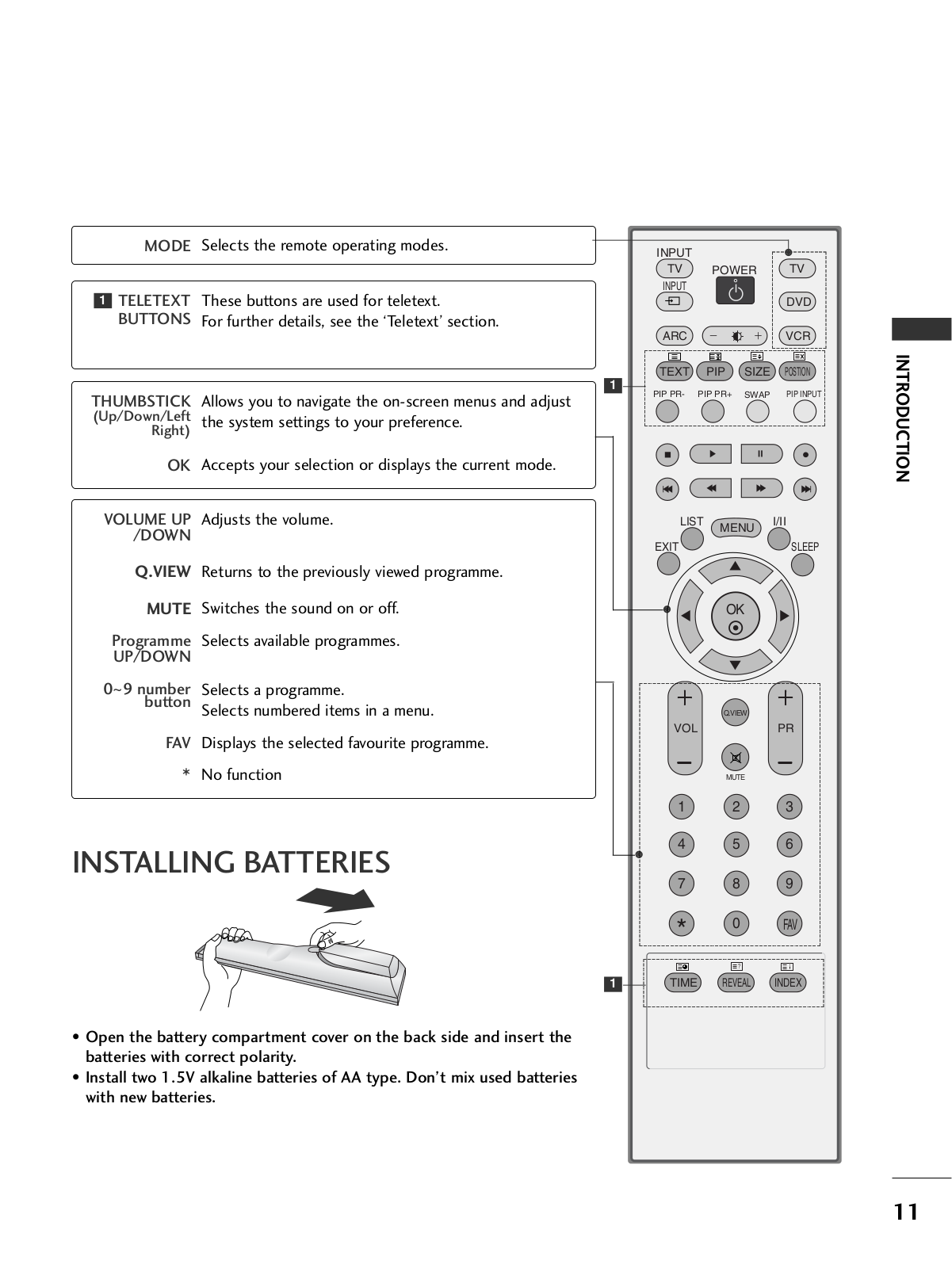
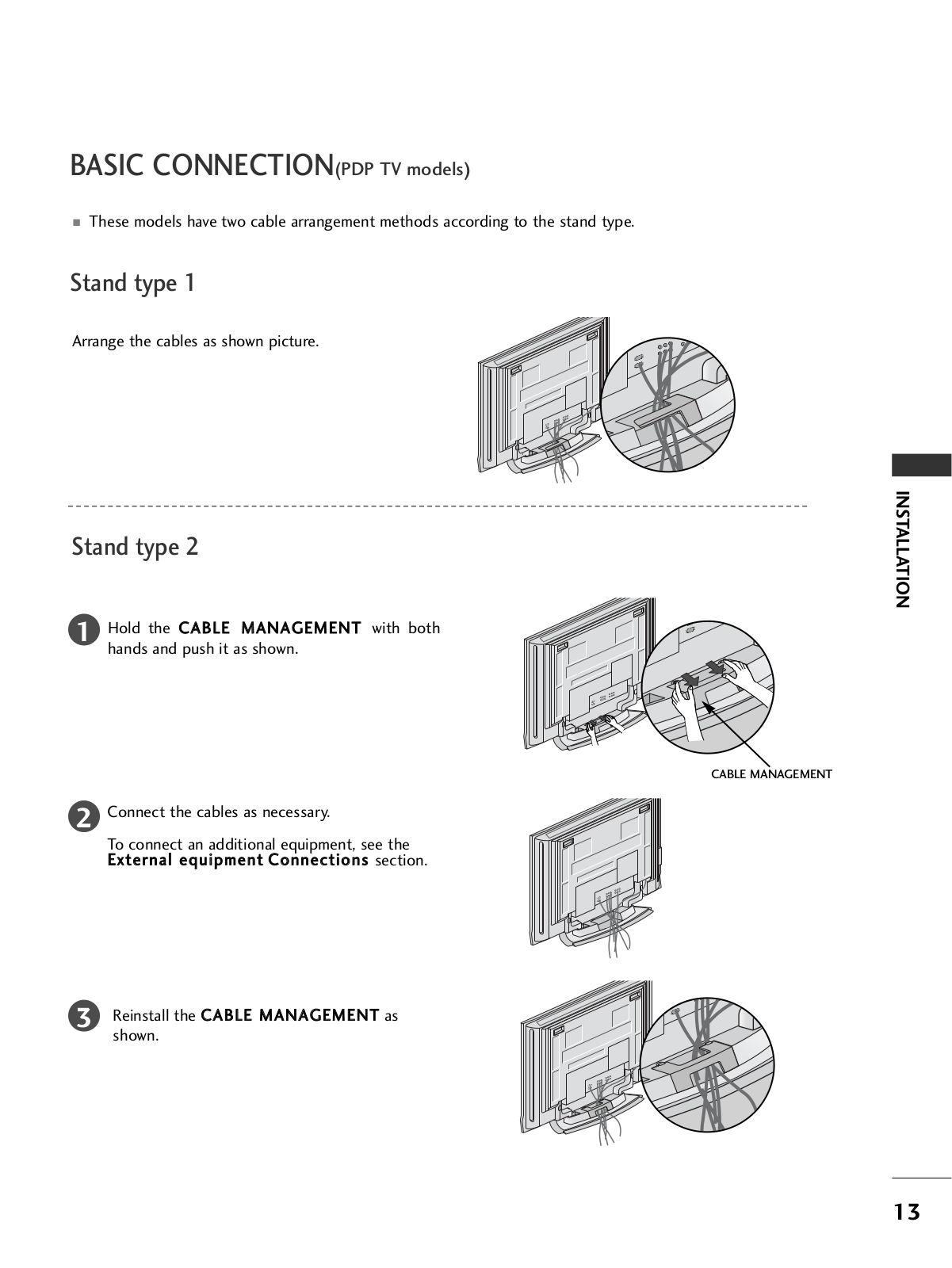
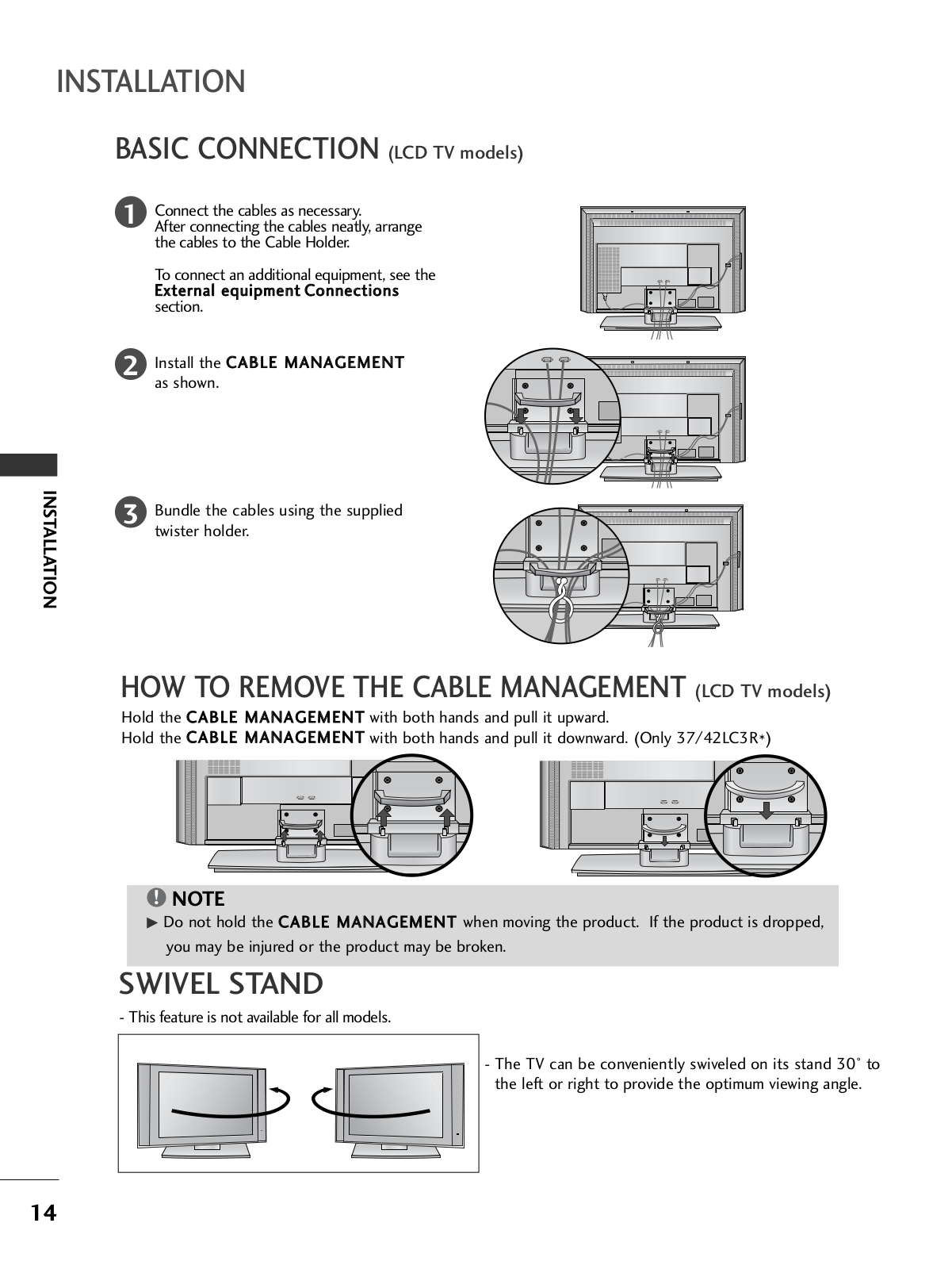
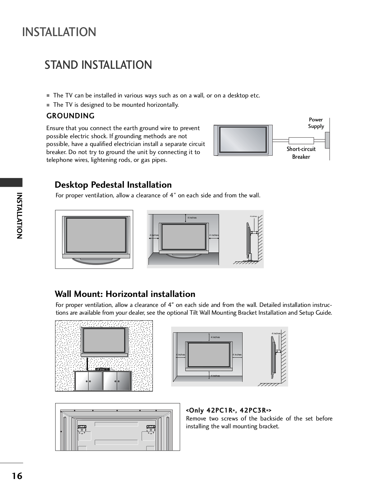
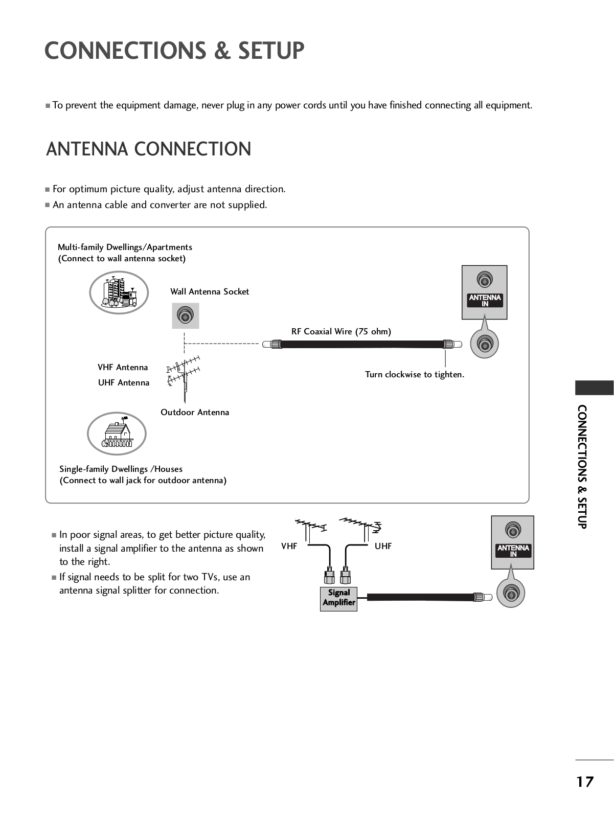
LG 47LB2RF, 32LB2R User Manual
...
LG User Manual
Download
Specifications and Main Features
Frequently Asked Questions
User Manual
Download
Loading...
+
56
hidden pages
Unhide
You need points to download manuals.
1 point = 1 manual.
You can buy points or you can get point for every manual you upload.
Buy points
Upload your manuals
 Loading...