

LG 44SZ8RUE Users manual

Test Report No.: GETEC-E3-05-038
FCC Class B Certification
APPENDIX H
: USER’S MANUAL
EUT Type: 44” DLP Projection TV
FCC ID: BEJ44SZ8RUE
OWNER'S MANUAL
DLPTM Projection Television
44HM85
5
Owner's Record
The model number and serial number are on the back
of your TV. Record these numbers in the spaces below.
Refer to these numbers whenever you communicate
with your Toshiba dealer about this TV.
Model:
Serial No.:
Lamp Unit Replacement
CAUTION: HOT SURFACE!
The temperature of the lamp
immediately after use
exceeds 392°F (200°C).
Touching the lamp before it has
cooled will result in severe burns. ALLOW THE LAMP TO
COOL FOR AT LEAST ONE (1) HOUR BEFORE REPLACING IT.
The exclamation mark in the triangle tells you that
important operating and maintenance instructions
follow this symbol.
The lightning symbol in the triangle tells you that
the voltage inside this product may be strong enough
to cause an electric shock. DO NOT TRY TO SERVICE
THIS PRODUCT YOURSELF.
The lamp in this product has a limited service life. The length
of service life varies depending on product use and user
settings. If you use the lamp beyond its service life:
• you may notice a reduction in the colors and/or brightness of
the picture, at which time you should replace the lamp unit;
and
• the strength of the quartz glass in the lamp will be reduced
and the lamp may rupture. If the lamp ruptures, the TV will
not operate until the lamp unit is replaced.
Note: The lamp unit is designed so broken lamp glass
remains securely inside the lamp unit.
See pages
50-52
.
• Dispose of the used lamp unit by the approved method for
your area.
NOTE TO CATV INSTALLERS
This is a reminder to call the CATV system installer’s attention
to Article 820-40 of the NEC, which provides guidelines for
proper grounding and, in particular, specifies that the cable
ground shall be connected to the grounding system of the
building, as close to the point of cable entry as practical. For
additional antenna grounding information, see items 27 and 28
on page 4.
Dear Customer,
Thank you for purchasing this Toshiba TV. This manual will
help you use the many exciting features of your new TV.
Before operating the TV, please read this manual completely,
and keep it nearby for future reference.
2500 Wilson Blvd.
Arlington, VA 22201 U.S.A.
Tel. 703-907-7600 Fax 703-907-7690
www.CE.org
CEA is the Sponsor, Producer and
Manager of the International CES
®
The Issue
W
If you are like most consumers, you have a TV in your
home. Many homes, in fact, have more than one TV.
W
The home theater entertainment experience is a growing
trend, and larger TVs are popular purchases; however, they are
not always supported on the proper TV stands.
W
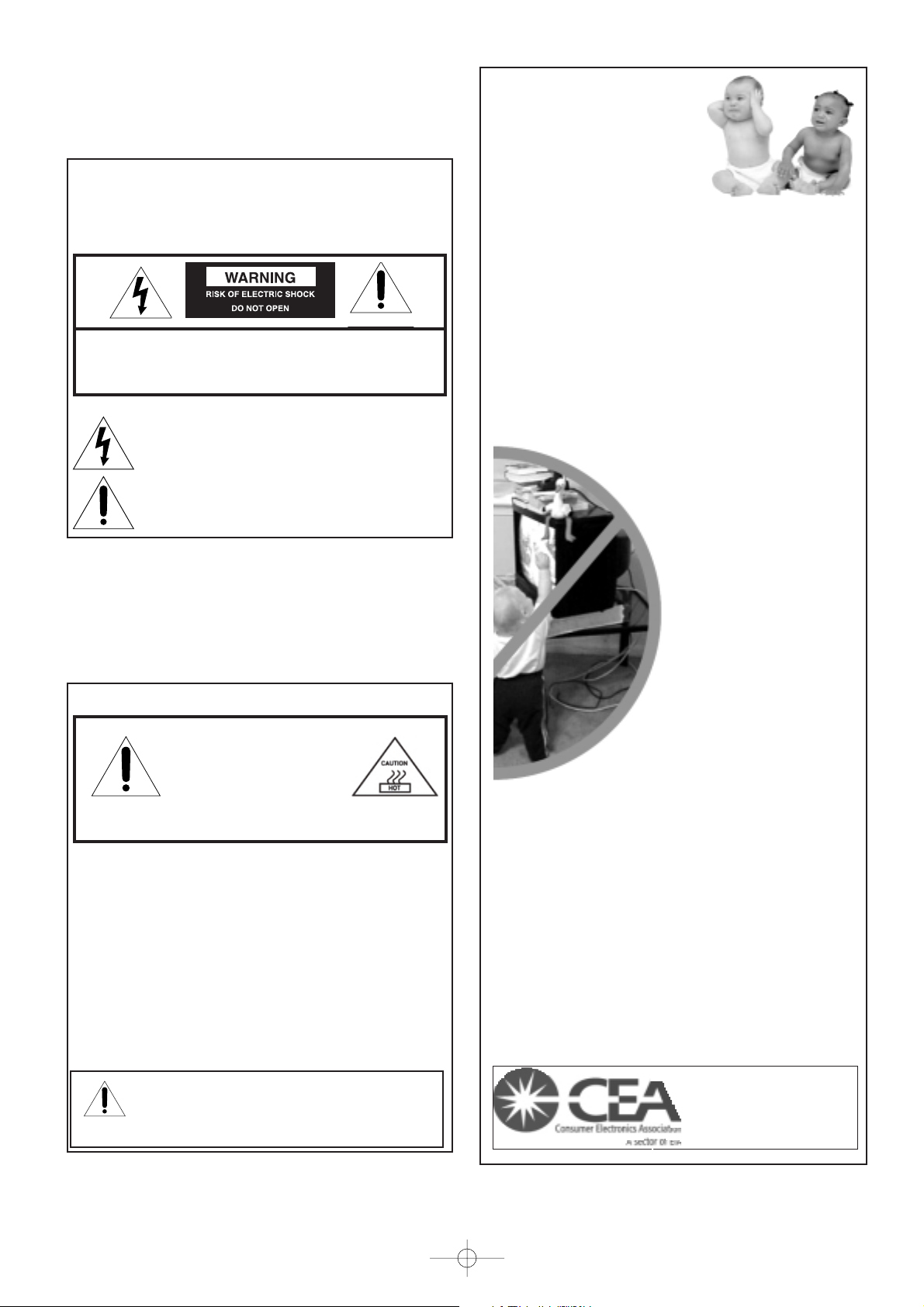
Sometimes TVs are improperly secured or inappropriately
situated on dressers, bookcases, shelves, desks, audio
speakers, chests, or carts. As a result, TVs may fall over,
causing unnecessary injury.
Toshiba Cares!
W
The consumer electronics industry is
committed to making home
entertainment enjoyable and safe.
W
The Consumer Electronics
Association formed the Home
Entertainment Support Safety
Committee, comprised of TV and
consumer electronics furniture
manufacturers, to advocate
children’s safety and educate
consumers and their families about
television safety.
Tune Into Safety
One size does NOT fit all! Use appropriate
furniture large enough to support the weight of
your TV (and other electronic components).
Use appropriate angle braces, straps, and anchors to secure
your furniture to the wall (but never screw anything directly
into the TV).
Carefully read and understand the other enclosed
instructions for proper use of this product.
Do not allow children to climb on or play with furniture
and TVs.
Avoid placing any item on top of your TV (such as a VCR,
remote control, or toy) that a curious child may reach for.
Remember that children can become excited while watching
a program and can potentially push or pull a TV over.
W
Share our safety message about this hidden hazard of
the
home with your family and friends. Thank you!
W
W
W
W
W
W
It Makes A Difference
Where Your TV Stands
Congratulations on your purchase! As you enjoy
your new TV, keep these safety tips in mind:
Child Safety
Note: The lamp unit contains mercury. Disposal of mercury may
be regulated due to environmental considerations. For disposal or
recycling information, contact your local authorities or the
Electronics Industries Alliance (www.eiae.org).
PAGE 2
Safety Precautions
WARNING
TO REDUCE THE RISK OF FIRE OR ELECTRIC SHOCK, DO NOT
EXPOSE THIS APPLIANCE TO RAIN OR MOISTURE.
WARNING: TO REDUCE THE RISK OF ELECTRIC SHOCK, DO NOT
REMOVE COVER (OR BACK). NO USER-SERVICEABLE PARTS
INSIDE. REFER SERVICING TO QUALIFIED SERVICE PERSONNEL.
562A_2~5(2) 10/5/11 7:10 PM Page 2
(continued on next page)
Installation, Care, and Service
Installation
Follow these recommendations and precautions and heed all
warnings when installing your TV:
17) Never modify this equipment. Changes or modifications may
void: a) the warranty, and b) the user’s authority to operate
this equipment under the rules of the Federal
Communications Commission.
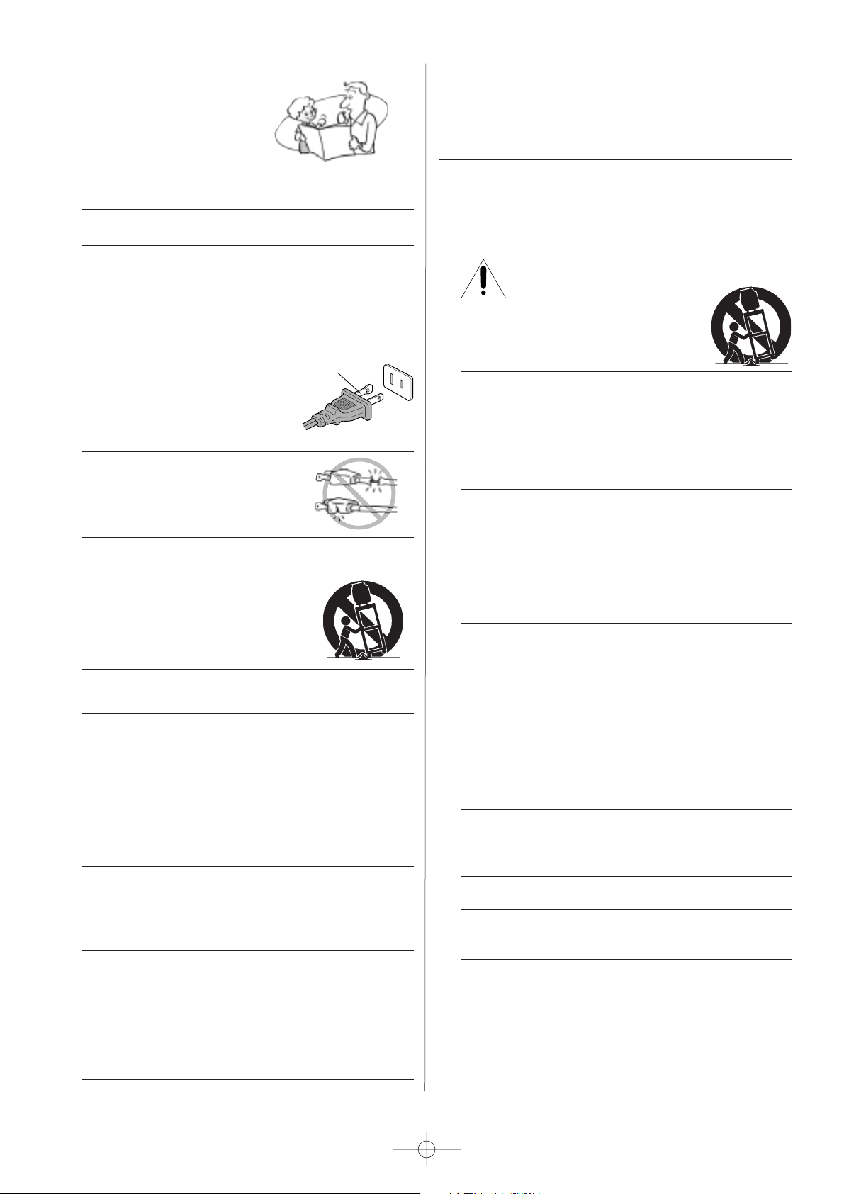
18) DANGER: RISK OF SERIOUS PERSONAL
INJURY, DEATH, OR EQUIPMENT
DAMAGE! Never place the TV on
an unstable cart, stand, or table. The TV
may fall, causing serious personal injury,
death, or serious damage to the TV.
19) Never place or store the TV in direct sunlight; hot, humid
areas; areas subject to excessive dust or vibration; or
locations with temperatures at or below 41°F (5°C).
20) Always place the TV on the floor or a sturdy, level, stable
surface that can support the weight of the unit.
21) Never expose the apparatus to dripping or splashing or
place items such as vases, aquariums, any other item filled
with liquid, or candles on top of the TV.
22) Always place the back of the television at least one (1)
inch away from any vertical surface (such as a wall) to
allow proper ventilation.
23) Never block or cover the slots or openings in the TV cabinet
back, bottom, and sides. Never place the TV:
• on a bed, sofa, rug, or similar surface;
• too close to drapes, curtains, or walls; or
• in a confined space such as a bookcase, built-in cabinet,
or any other place with poor ventilation.
The slots and openings are provided to protect the TV from
overheating and to help maintain reliable operation of the
TV.
24) Never allow anything to rest on or roll over the power cord,
and never place the TV where the power cord is subject to
wear or abuse.
25) Never overload wall outlets and extension cords.
26) Always operate this equipment from a 120 VAC, 60 Hz
power source only.
Important Safety Instructions
1) Read these instructions.
2) Keep these instructions.
3) Heed all warnings.
4) Follow all instructions.
5) Do not use this apparatus near water.
6) Clean only with a dry cloth.
7) Do not block any ventilation openings. Install in
accordance with the manufacturer’s instructions.
8) Do not install near any heat sources such as radiators,
heat registers, stoves, or other apparatus (including
amplifiers) that produce heat.
9) Do not defeat the safety purpose of the polarized or
grounding type plug. A polarized plug has two blades
with one wider than the other. A grounding type plug has
two blades and a third grounding
prong. The wide blade or the third
prong are provided for your safety.
If the provided plug does not fit into
your outlet, consult an electrician
for replacement of the obsolete outlet.
10) Protect the power cord from being
walked on or pinched, particularly at
plugs, convenience receptacles, and
the point where it exits the apparatus.
11) Only use attachments/accessories specified by the
manufacturer.
12) Use only with the cart, stand, tripod,
bracket, or table specified by the
manufacturer, or sold with the
apparatus. When a cart is used, use
caution when moving the cart/apparatus
combination to avoid injury from tip-over.
13) Unplug this apparatus during lighting storms or when
unused for long periods of time.
14) Refer all servicing to qualified service personnel.
Servicing is required when the apparatus has been damaged
in any way, such as power-supply cord or plug is damaged,
liquid has been spilled or objects have fallen into the
apparatus, or the apparatus has been exposed to rain or
moisture, does not operate normally, or has been dropped.
This applies to all items except those specified on pages
50-52 of this manual.
15) CAUTION: To reduce the risk of electric shock, do not use
the polarized plug with an extension cord, receptacle, or
other outlet unless the blades can be inserted completely
to prevent blade exposure.
16) WARNING: This product contains a lamp to project the
picture, and requires special safety precautions:
• See pages 50-52 for instructions on lamp unit
replacement.
• DO NOT attempt to service this product except as
specified on pages 50-52. The only user-serviceable
item in this product is the lamp unit.
Wide plug
PAGE 3
562A_2~5(2) 10/5/11 7:10 PM Page 3
Care
(cont. from previous column)
33) For added protection of your TV from lightning and power
surges, always unplug the power cord and disconnect the
antenna from the TV if you leave the TV unattended or
unused for long periods of time.
34
) During normal use, the TV may make occasional snapping or
popping sounds. This is normal, especially when the unit is
being turned on or off. If these sounds become frequent or
continuous, unplug the power cord
and contact a Toshiba Authorized Service Center.
35)
Special care for DLP
TM
(digital light processing) units:
•
Lamp—The lamp in this product has a limited service life.
The length of service life varies depending on product use
or user settings. If you use the lamp beyond its service
life:
- you may notice a reduction in the colors and/or
brightness of the picture, at which time you should
replace the lamp unit; and
- the strength of the quartz glass in the lamp will be
reduced and the lamp may rupture. If the lamp ruptures,
the TV will not operate until the lamp unit is replaced.
See pages 50-52.
Note:
• The lamp unit is designed so broken lamp glass remains
securely inside the lamp unit.
• The lamp unit contains mercury. Disposal of
mercury may be regulated due to environmental
considerations. For disposal or recycling information,
please contact your local authorities or the
Electronics Industries Alliance (www.eiae.org).
• Dispose of the used lamp unit by the approved method for
your area.
Service
36
) WARNING: RISK OF ELECTRIC SHOCK!
Never attempt to service the TV yourself,
except as specified on pages 50-52.
Opening and removing the covers may expose you to
dangerous voltage or other hazards. Failure to follow this
WARNING may result in death or serious injury. Refer all
servicing not specified in this manual to a Toshiba Authorized
Service Center.
37) If you have the TV serviced:
• Ask the service technician to use only replacement parts
specified by the manufacturer.
• Upon completion of service, ask the service technician to
perform routine safety checks to determine
that the TV is in safe operating condition.
38) When the TV reaches the end of its useful life, ask a
qualified service technician to properly dispose of the TV.
Note: The lamp unit contains mercury. Disposal of mercury may
be regulated due to environmental considerations. Dispose of the
used lamp unit by the approved method for your area.
For disposal or recycling information, please contact your local
authorities or the Electronics Industries Alliance (www.eiae.org).
Installation
(cont. from previous page)
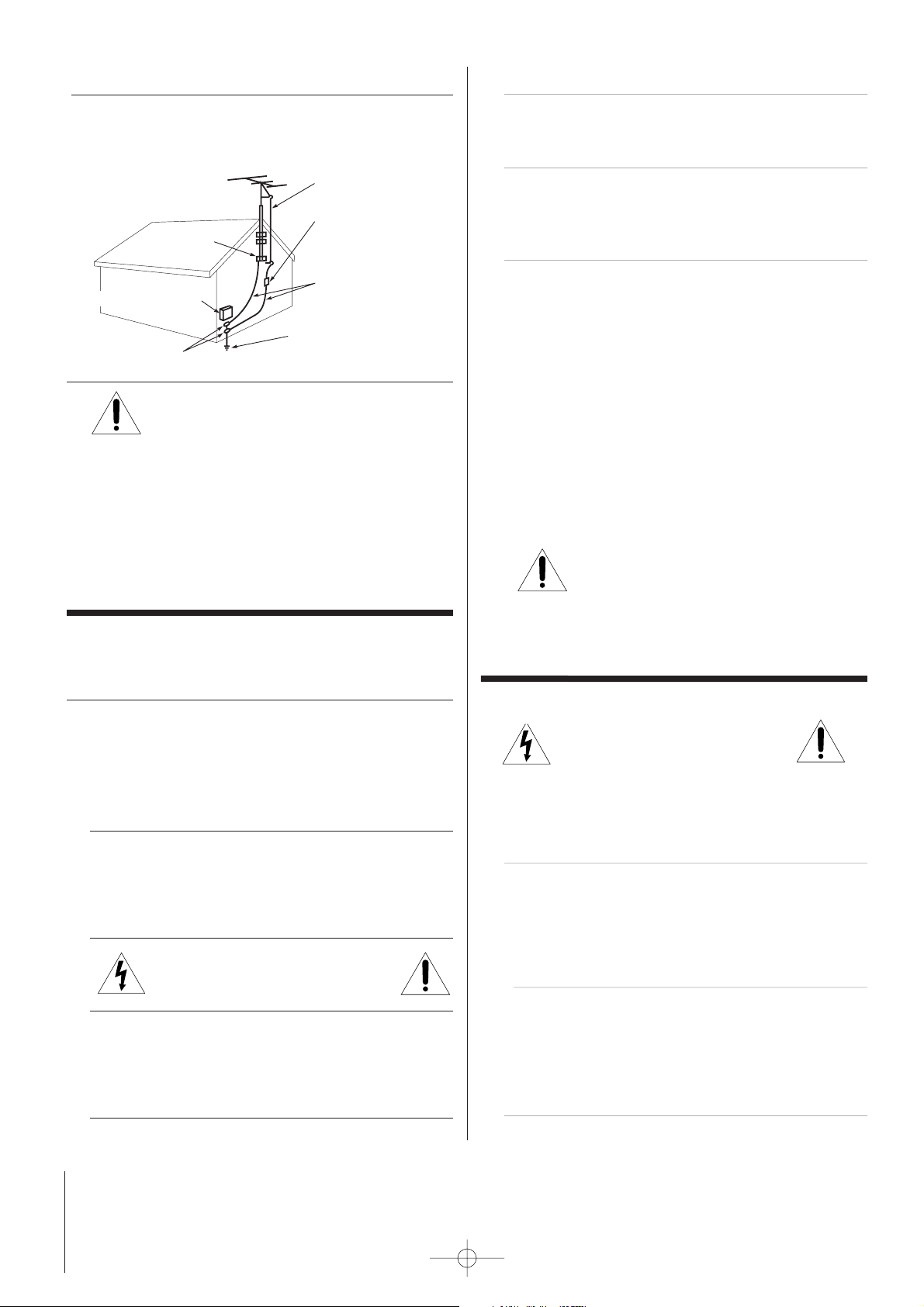
27) Always make sure the antenna system is properly grounded
to provide adequate protection against voltage surges and
built-up static charges (see Section 810 of the National
Electric Code).
28) DANGER: RISK OF SERIOUS PERSONAL
INJURY OR DEATH!
• Use extreme care to make sure you are never in
a position where your body (or any item you are in contact
with, such as a ladder or screwdriver) can accidentally
touch overhead power lines. Never locate the antenna near
overhead power lines or other electrical circuits.
• Never attempt to install any of the following during
lightning activity:
a) an antenna system; or b) cables, wires, or any home
theater component connected to an antenna or phone
system.
Care
For better performance and safer operation of your TOSHIBA TV,
follow these recommendations and precautions:
29) Always sit approximately 10–25 feet away from the TV and
as directly in front of it as possible. The picture can appear
dull if you sit too far to the left or right of the TV, or if
sunlight or room lights reflect on the screen. Turn the TV
off to check for reflections on the screen, and then remove
the source of reflections while viewing the TV.
30) Always unplug the TV before cleaning. Never use liquid or
aerosol cleaners. Clean only with a dry cloth.
Do not spray volatile compounds such as insecticide on the
cabinet. This may cause a discoloration or damage of the
cabinet.
31) WARNING: RISK OF ELECTRIC SHOCK!
Never spill liquids or push objects of any
kind into the TV cabinet slots.
32) If the air temperature rises suddenly (for example, when
the TV is first delivered), condensation may form on the
lenses. This can make the picture appear distorted or the
color appear faded. If this happens, turn off the TV for 6 to
7 hours to allow the condensation to evaporate.
Ground clamp
Antenna discharge unit
(NEC Section 810-20)
Grounding conductors
(NEC Section 810-21)
Power service grounding
electrode system (NEC Art 250 Part H)
Ground clamps
Antenna lead-in wire
Electric service equipment
PAGE 4
562A_2~5(2) 10/5/11 7:10 PM Page 4
5) Always sit approximately 10–25 feet away from the TV and as
directly in front of it as possible. The picture quality may be
affected by your viewing position and length of viewing time.
If you sit too closely to the TV for too long, you may suffer
from eye fatigue. See item 29 on page 4.
6) This TV contains several cooling fans to moderate
the internal temperature. You may be able to hear
the fans noise during or after operation.
7) Always place the back of the television at least one (1) inch
away from any vertical surface (such as a wall) to allow
proper ventilation.
8) Review all safety and operating information in this owner’s
manual before you use your TV.
9) Interactive video games that involve shooting a “gun” type
of joystick at an on-screen target may not work on this TV.
1) The light source for this TV is a projection lamp unit with a
limited service life. When the lamp wears out, the picture
may become dark or black, or the lamp may fail, at which
time you must replace the lamp unit. See “Lamp unit
replacement” on pages 50-52.
2) Each time you turn on the TV, it may take up to several
seconds to go from no picture to full picture brightness.
3) The display on this TV is manufactured using an extremely
high level of precision technology; however, an occasional
pixel (dot of light) may show constantly on the screen. This
is a structural property of micro-display projection TV
technology, and is not a sign of malfunction. Such pixels are
not visible when the picture is viewed from a normal viewing
distance (see item 29 on page 4).
4) Depending on the media you are viewing, it is possible,
although unlikely, that a limited number of viewers may see
a “rainbow effect” on the screen, which can, in rare
instances, result in eye fatigue. This is a rare occurrence
related to technology of this type, and is not a sign of TV
malfunction.
Important notes about your DLPTM projection TV
562A_2~5(2) 10/5/11 7:10 PM Page 5
FCC Compliance Statement
This equipment has been tested and found to comply with the limits for a Class B digital device, pursuant to part 15 of
the FCC Rules. These limits are designed to provide reasonable protection against harmful interference in a
residential installation. This equipment generates, uses and can radiate radio frequency energy and, if not installed
and used in accordance with the instructions, may cause harmful interference to radio communications. However,
there is no guarantee that interference will not occur in a particular installation. If this equipment does cause
harmful interference to radio or television reception, which can be determined by turning the equipment off and on,
the user is encouraged to try to correct the interference by one or more of the following measures:
- Reorient or relocate the receiving antenna.
- Increase the separation between the equipment and receiver.
- Connect the equipment into an outlet on a circuit different from that to which the receiver is connected.
- Consult the dealer or an experienced radio/TV technician for help.
.
CAUTION
The users manual or instrucuion manual for an intentional or unintentional radiator shall caution the user that changes
or modifications not expressly approved by the party responsible for compliance could void the user's authority to
operate the equipment.
PAGE 5
PAGE 6
Table of Contents
Setup Checklist
Safety Warnings . . . . . . . . . . . . . . . . . . . . . . . . . . . .2
Important Safety Instructions . . . . . . . . . . . . . . . . .3-4
Function Status Indicators . . . . . . . . . . . . . . . . . . . . .6
Step 1. Hook Up TV
Rear Connections Panel . . . . . . . . . . . . . . . . . . . . . . .7
Front Connections Panel . . . . . . . . . . . . . . . . . . . . . .8
ANT/Cable Service Hookup . . . . . . . . . . . . . . . . . . . . .9
Cable Box Connections . . . . . . . . . . . . . . . . . . . . . . .10
VCR Connections . . . . . . . . . . . . . . . . . . . . . . . . . . .11
DVD Player . . . . . . . . . . . . . . . . . . . . . . . . . . . . . .12
RGB-DTV/DVI-DTV Input . . . . . . . . . . . . . . . . . . . . . .13
RGB-PC/DVI-PC Input . . . . . . . . . . . . . . . . . . . . . . .14
External Stereo Connections . . . . . . . . . . . . . . . . . . .15
Home Theater: Speaker Layout . . . . . . . . . . . . . . . . .16
Monitor Out Setup . . . . . . . . . . . . . . . . . . . . . . . . .17
Remote Control Functions in TV Mode . . . . . . . . . . .18-19
On-Screen Displays . . . . . . . . . . . . . . . . . . . . . . . . .20
Front Panel Controls . . . . . . . . . . . . . . . . . . . . . . . .21
Step 2. Customize your TV’s Features
SETUP Menu
Auto Program: Channel Search . . . . . . . . . . . . . . . . . . . . .22
Manual Program: Adding/Deleting Channels . . . . . . . . . . . . . .23
Fine Tuning Adjustment . . . . . . . . . . . . . . . . . . . . . . . .24
Signal Reception Booster
. . . . . . . . . . . . . . . . . . . . . . . 25
Favorite Channels Setup
. . . . . . . . . . . . . . . . . . . . . . . .28
VIDEO Menu Options . . . . . . . . . . . . . . . . . . . . .29-30
AUDIO Menu Options . . . . . . . . . . . . . . . . . . . . .31-32
TIME Menu Options
Auto Clock Setup . . . . . . . . . . . . . . . . . . . . . . . . .33
Manual Clock Setup . . . . . . . . . . . . . . . . . . . . . . . .34
TV Turn Off Timer Setup . . . . . . . . . . . . . . . . . . . . .35
TV Turn On Timer Setup . . . . . . . . . . . . . . . . . . . . .36
Sleep Timer Setup . . . . . . . . . . . . . . . . . . . . . . . . .37
Auto Off . . . . . . . . . . . . . . . . . . . . . . . . . . . . . . .38
SPECIAL Menu Options
Aspect Ratio . . . . . . . . . . . . . . . . . . . . . . . . . . . .39
On-Screen Menu Languages . . . . . . . . . . . . . . . . . . 40
Captions Setup . . . . . . . . . . . . . . . . . . . . . . . . . . .41
Caption/Text Mode Selection . . . . . . . . . . . . . . . . . .42
Key Lock . . . . . . . . . . . . . . . . . . . . . . . . . . . . . . .43
Cinema Mode Setup . . . . . . . . . . . . . . . . . . . . . . . .44
Demo (Menu Review) . . . . . . . . . . . . . . . . . . . . . . .45
SCREEN Menu Options
LOCK Menu Options
Parental Lock Setup . . . . . . . . . . . . . . . . . . . . . . . .46
Parental Lock (Ratings Overview) . . . . . . . . . . . . . . .47
PIP/Twin Picture Operation
POP
Step 3. Miscellaneous
Programming the Remote . . . . . . . . . . . . . . . . . . . . .48
Programming Codes . . . . . . . . . . . . . . . . . . . . . .49-52
Maintenance . . . . . . . . . . . . . . . . . . . . . . . . . . . . .53
Troubleshooting . . . . . . . . . . . . . . . . . . . . . . . . .54-55
Glossary . . . . . . . . . . . . . . . . . . . . . . . . . . . . . .56-57
Product Specifications . . . . . . . . . . . . . . . . . . . . . .58
Warranty . . . . . . . . . . . . . . . . . . . . . . . . . . . . .59-60
Step 1. Make all equipment and source connections.
See pages 10-17.
Step 2. Install batteries in remote control and do a channel search.
See page 22.
Step 3. Adjust TV features and options to your preference.
See contents above.
Note: Design and specifications are subject to change without prior notice.
PAGE 7
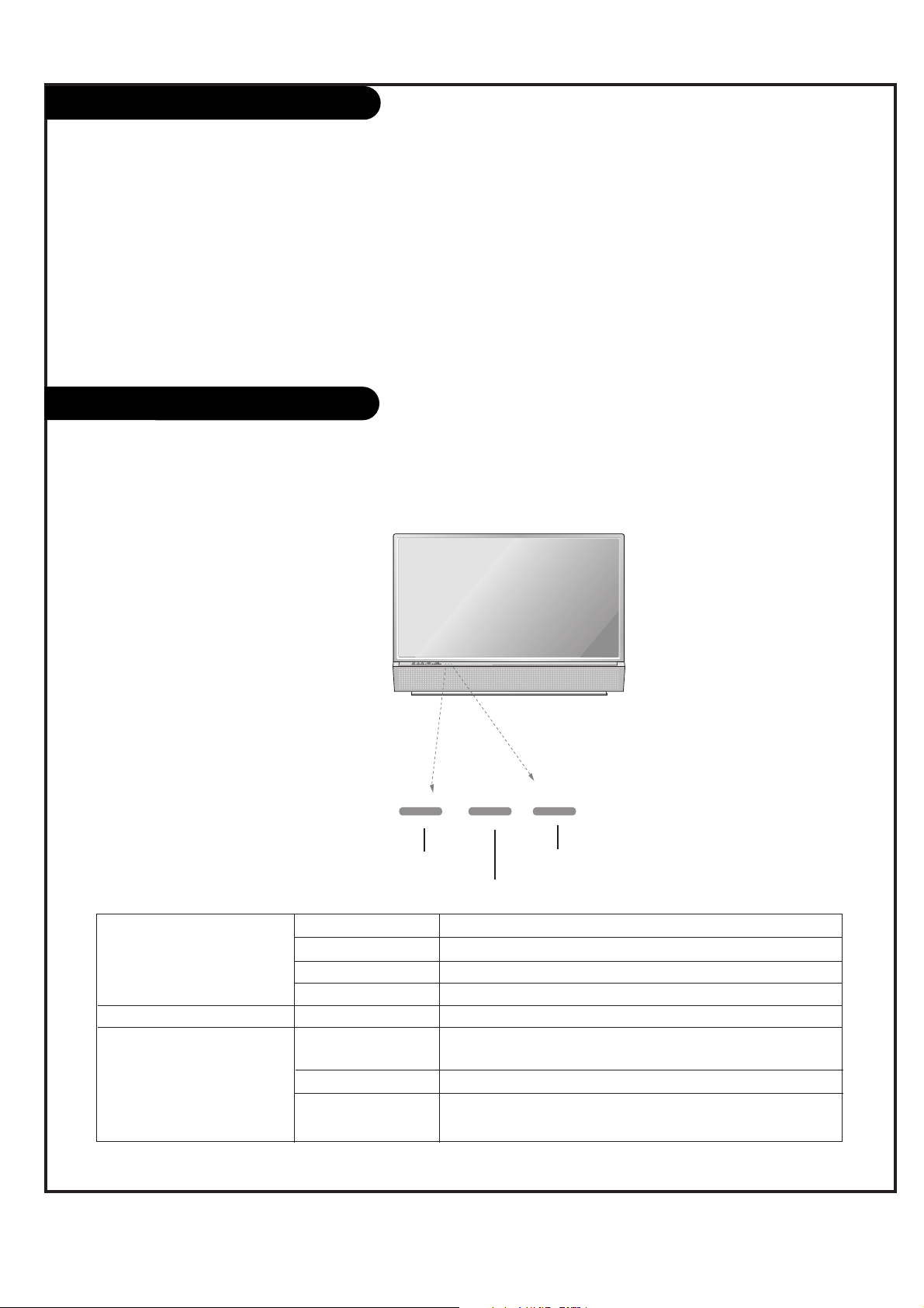
Function Status Indicators
Lamp indicator, operation indicator, and temperature indicator located below the front panel controls,
reveal the operating status of the DLP projection TV.
Operation Indicator
Lamp Indicator
Temperature Indicator
Off Power cord is not connected.
Red Power Cord is connected, TV is in standby mode.
Green TV turns on.
Orange (flashing) Preparing operation in standby mode.
Green (flashing) The lamp cover is not closed.
Orange The projection TV is overheating. Check the blocked vents of
the projection TV .
Red The projection TV shut down due to overheating.
Red (flashing) The projection TV shut down due to the cooling fan trouble.
Contact an authorized service center.
Operation Indicator
Lamp Indicator
Temperature Indicator
Welcome to Toshiba
Welcome to Toshiba
Congratulations! You have purchased one of the finest DLPTMprojection TVs on the market. The goal of this manual is to
guide you through setting up and operating your Toshiba TV as quickly as possible.
This manual applies to models 44NHM84. The model and serial numbers are on the back of your TV. Write these numbers
in the space provided on the front cover of this manual for your records.
Instructions in this manual are based on using the remote control. You can also use the controls on the TV if they have
the same name as those on the remote control.
Please read all the safety and operating instructions carefully, and keep the manual for future reference.
PAGE 8
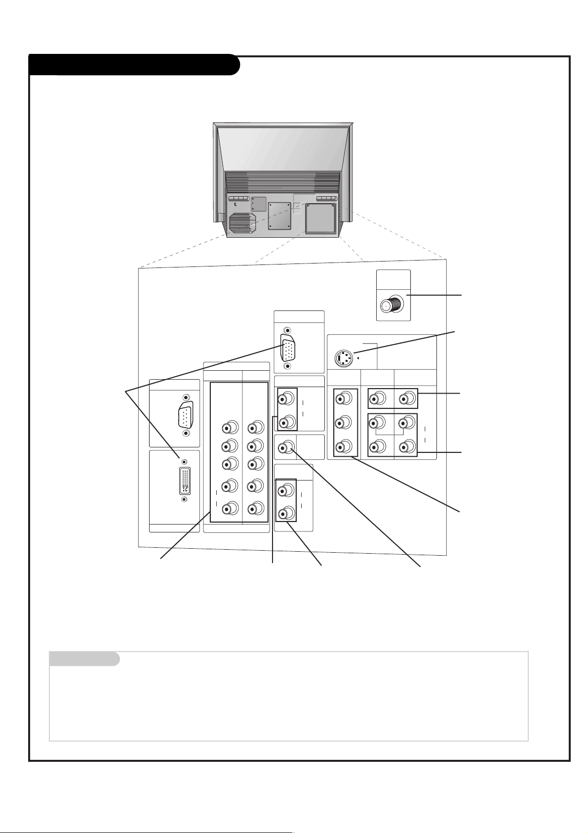
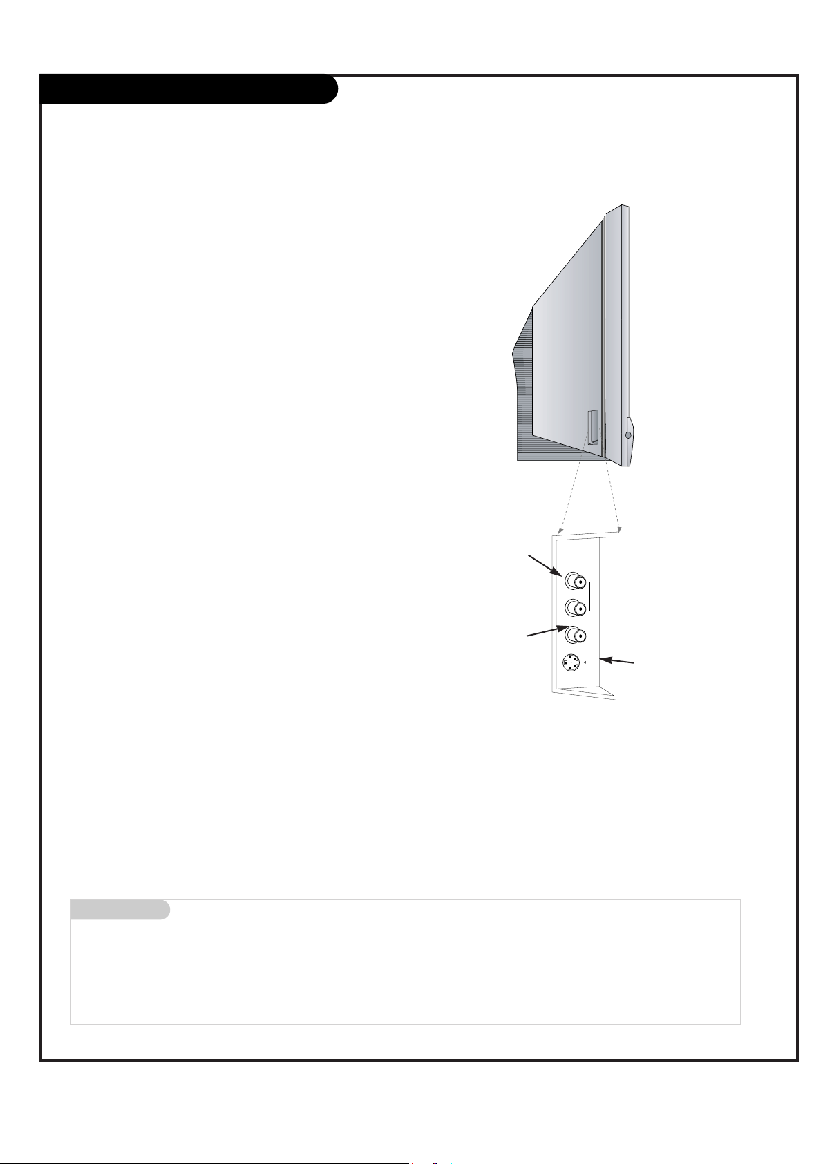
Rear Connections Panel
Mini glossary
JACK A connection on the back of a TV, VCR, or any other A/V device. This includes the RF jack and the Audio/Video jacks that are color-
coded.
SIGNAL Picture and sound traveling through cable, or over the air, to your television screen.
S-VIDEO In
A connection available with
some high-end equipment
that provides even better
picture quality for Video 2.
Variable Audio Out
Used to connect either
an external amplifier, or
add a sub-woofer to your
surround sound system.
RF Connector: Antenna
Used to connect analog
cable or antenna signals to
the television, either
directly or through your
cable box.
Video 1 or 2
Connects the video signals from various types of
equipment.
Component Input 1-2
Connect a component video/audio device
to these jacks. Refer to your DVD manual
for further information.
Connecting cables and external equipment to your TV.
This manual explains the features available
on the 44SZ8R TVs.
Monitor Out
Connects to a second TV or
Monitor.
Left/Right Audio
Used for stereo sound
from various types of
equipment.
RGB/DVI Input
Connect the TV output con-
nector from a PC/DTV to the
appropriate input port.
RGB/DVI Input
Used for audio connections
from a PC source or HD-STB
Satellite system.
Audio Center Mode In
Connect to external Dolby
Digital Center “preamp output.”
UPGRADE PORT
PC/DTV
(XGA/
480p/
720p/
1080i)
DVI INPUT
Y
PB
PR
(L)
AUDIO
(R)
COMPONENT
INPUT2
(480i/
480p/
720p/
1080i)
DTV/DVD
INPUT1
(480i/
480p/
720p/
1080i)
RGB INPUT
PC/DTV
(XGA/
480p/
720p/
1080i)
RGB/DVI INPUT
(L)
AUDIO
(R)
AUDIO
CENTER
MODE IN
VARIABLE
AUDIO OUT
(L)
AUDIO
(R)
S-VIDEO
MONITOR
OUT
MONO
VIDEO
INPUT 2
ANT IN
+75 Ω
VIDEO
INPUT 1
VIDEO
(L)
AUDIO
(R)
PAGE 9
Front Connection Panel
There are four jacks on the left side on your projection TV that
make connecting Audio/Video devices like video games and camcorders very simple.
The jacks are like those found on the back jack connection panel.
This means that most equipment that connects to those types of
jacks on the rear jackpack, may be connected to the front connection panel.
To use the front jacks as the signal source, select them using
Main Input menu as described on page 25. They will be named
“Front Video” in the Main Input menu.
If you input both Front Video and SVideo, only the S-Video will work.
If you’re connecting a video game
device, make sure to change the
picture settings with the EZ Picture
option in the Video menu (see page
29).
Mini glossary
A/V CABLES Audio/Video cables. Three cable connector—Right audio (red), Left audio (white), and Video (yellow). A/V cables are used for stereo
playback of videocassettes and for higher quality picture and sound from other A/V devices.
A/V DEVICE Any device that produces video or sound (VCR, DVD, cable box, or television).
Left/Right Audio
Used for stereo sound
from various types of
equipment.
Video
Connects the video
signals from any
piece of equipment.
S-Video
A connection available on
some very high-end equipment
that provides better picture
quality than video input.
W
W
Front A/V Panel
)
R
(
AUDIO
/
)
L
(
O
N
O
M
VIDEO
S-VIDEO
FRONT A/V
PAGE 10
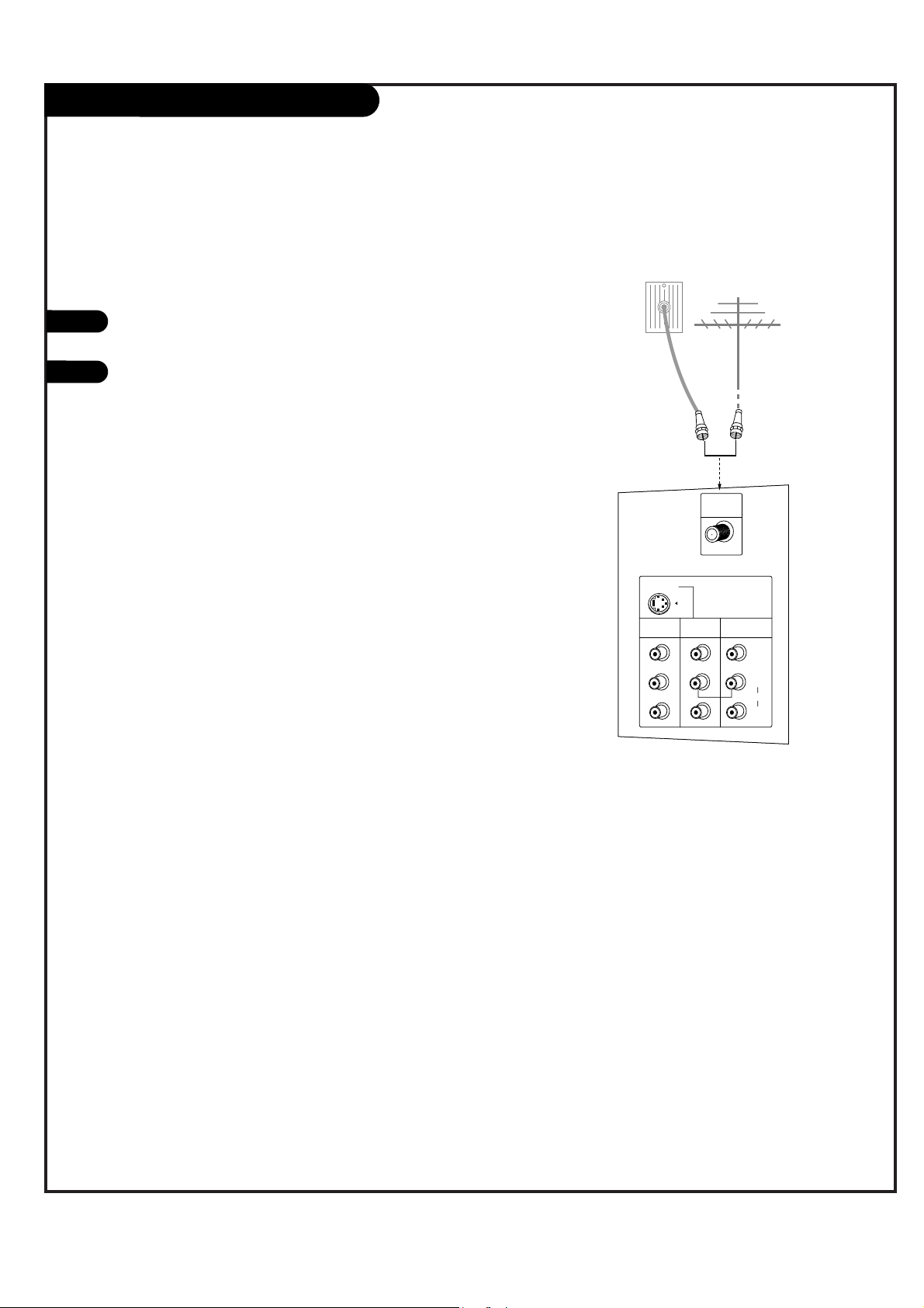
ANT / Cable Service Hookup
1
Connect an antenna or cable service to your
TV as shown.
Turn to page 22 to do a channel search
with EZ Scan for Ant/Cable connection(s).
For best signal reception, it is recommended to have your Antenna professionally adjusted.
2
If you receive your RF signal
through an antenna that is several
years old and connects with two
small prongs, you will need to purchase a 300 to 75 ohm adapter. It
should be available from your local
electronics dealer.
We recommend using a 75 ohm
cable for your antenna connections
in order to prevent
interference.
MONITOR
OUT
VIDEO
INPUT 2
VIDEO
INPUT 1
S-VIDEO
(R)
(L)
AUDIO
VIDEO
MONO
+75 Ω
ANT IN
MONITOR
OUT
VIDEO
INPUT 2
VIDEO
INPUT 1
S-VIDEO
(R)
(L)
AUDIO
VIDEO
MONO
+75 Ω
ANT IN
Antenna
Cable TV
Wall Jack Panel
RF Coaxial Wire
(75 ohm)
RF Coaxial Wire
(75 ohm)
W
W
PAGE 11
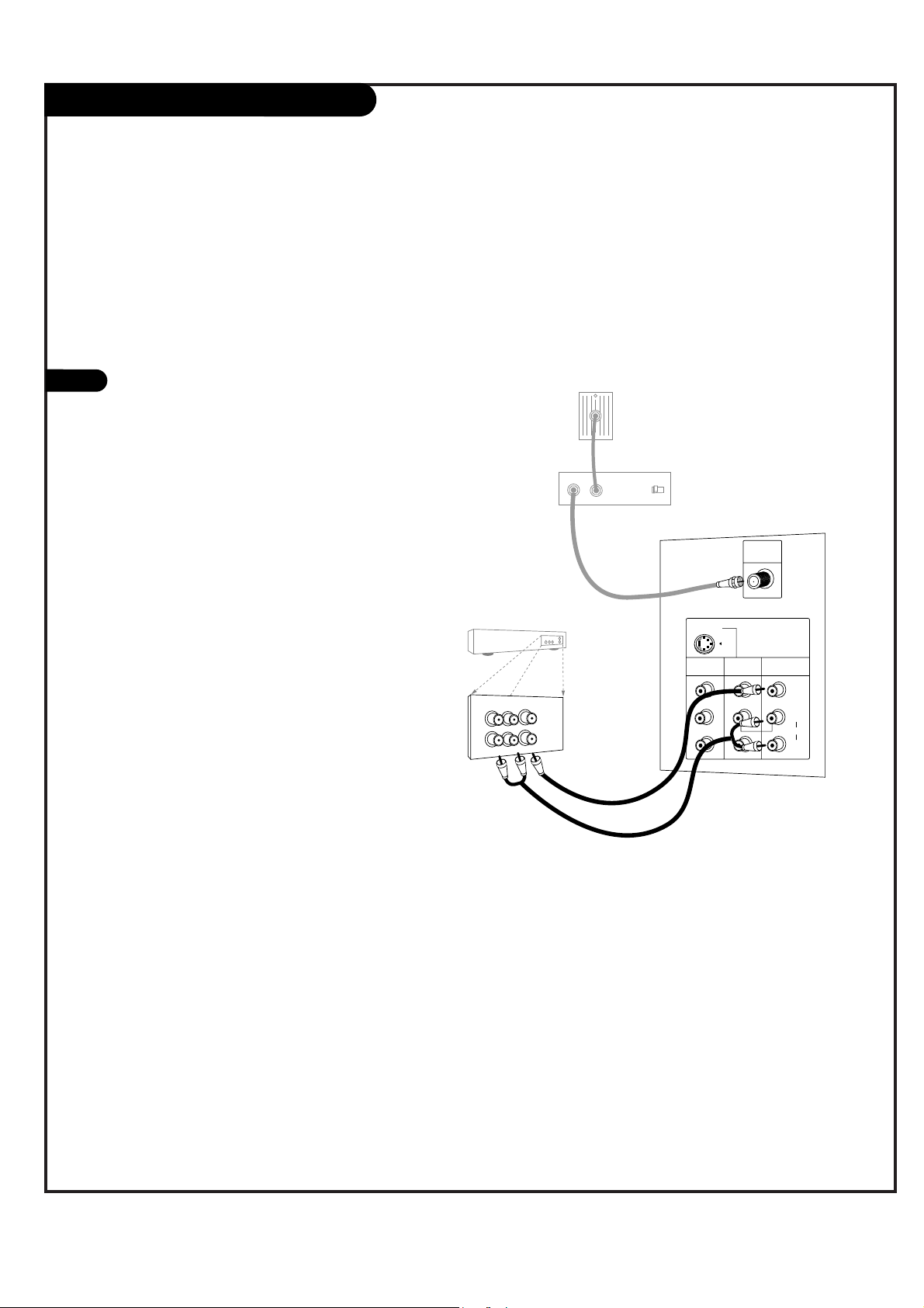
Cable Box Connections
Locate the output jack on the back of
your cable box. Connect this to the
Antenna jack on the back of your TV.
Or find the composite video and audio
jacks on the back of your cable box, and
connect them following the instructions
provided with your equipment.
This can be combined with any other
equipment you may want to hook up.
1
In
Output
Switch
Out
3 4
MONITOR
OUT
VIDEO
INPUT 2
VIDEO
INPUT 1
S-VIDEO
(R)
(L)
AUDIO
VIDEO
MONO
+75 Ω
ANT IN
Audio
TV
VCR
L
R
Video
Cable TV
Wall Jack Panel
RF Coaxial Wire
(75 ohm)
Cable Box
If you’re using a cable box, leave the TV on
channel 3 or 4 and use your cable box to
change channels.
W
PAGE 12
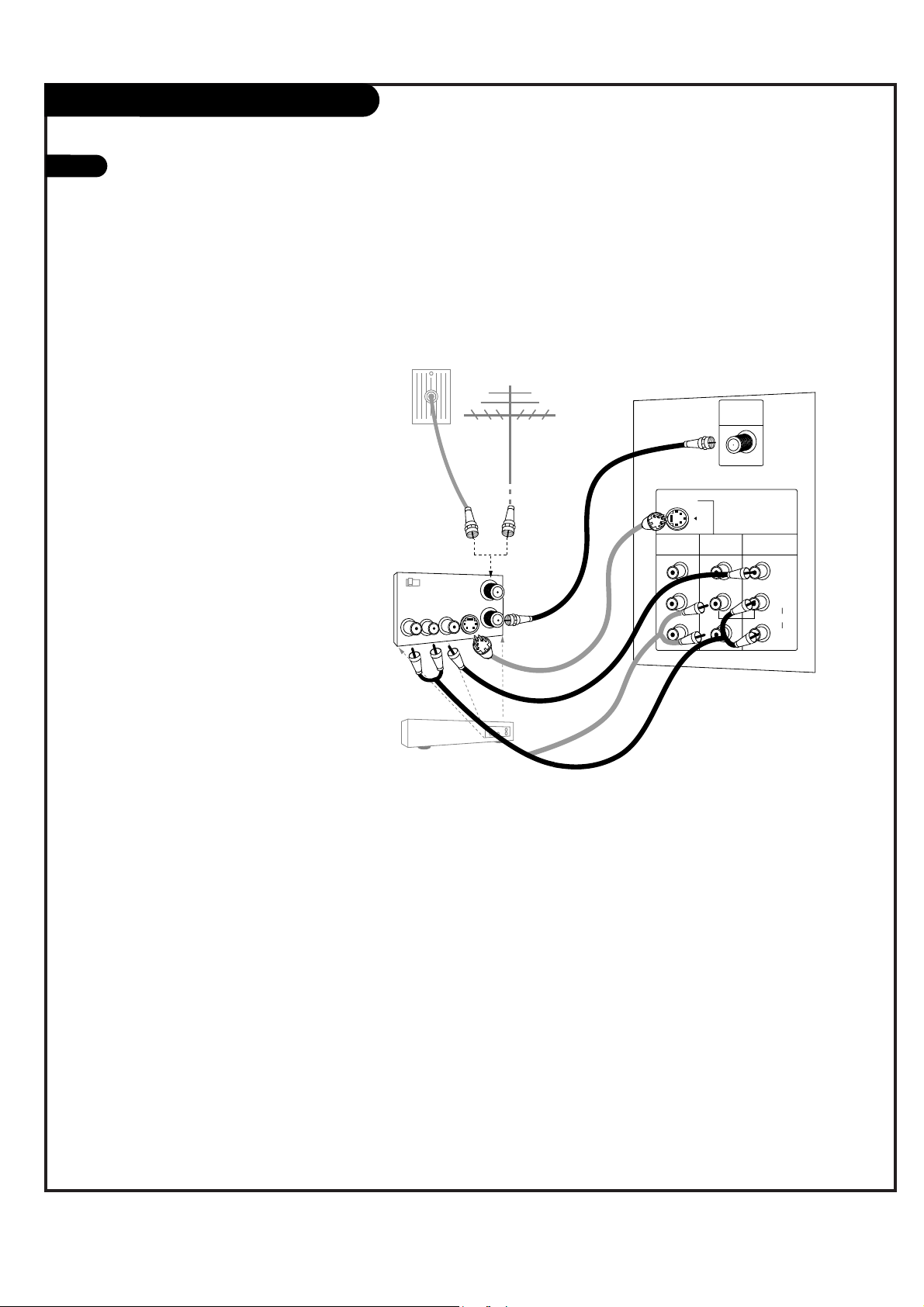
1
VCR Connections
Locate the Antenna jack on the
back of your TV. Connect this to
RF out jack on the back of your
VCR.
Or, find the composite video and
audio jacks on the back of your
VCR, and connect them following
the instructions provided with
your equipment.
You may connect either the composite video or the S-Video cables
to your TV. (Do not connect both
the composite and the S-Video
cables. In the event that you connect both composite and the SVideo cables, only the S-Video will
work.)
To hear stereo sound from cable or your VCR,
you will need to connect A/V cables as well as
the wire that runs from the VCR to your TV.
If you want to receive your signals on Channel
3 or 4, locate the Out to TV jack on your VCR.
Connect a cable from the Out to TV jack to the
Antenna In jack on the back of your TV.
After connecting external equipment to the TV,
don’t display a still picture for a long time on
the screen. Doing so may damage the TV
screen.
MONITOR
OUT
VIDEO
INPUT 2
VIDEO
INPUT 1
S-VIDEO
(R)
(L)
AUDIO
VIDEO
MONO
+75 Ω
ANT IN
In
Out
Audio
L
R
Video
3 4
S-Video
Output
Switch
Antenna
RF Coaxial Wire
(75 ohm)
Round Wire
(75 ohm)
A/V cables
not included
with TV
VCR
Back AV Panel
Cable TV
Wall Jack Panel
W
W
W
PAGE 13
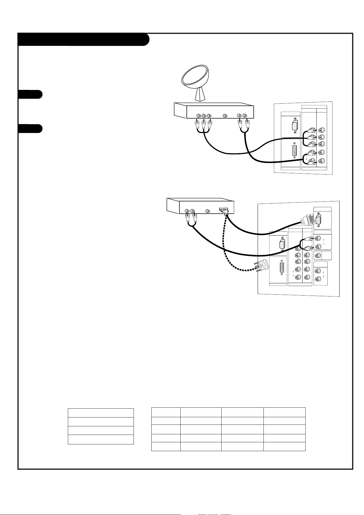
DVD Player
Mini glossary
COMPONENT VIDEO Some video equipment uses three separate lines (Y, P
B, PR) to more precisely reproduce images. Your video equipment manual
will explain how this relates to your equipment.
Find the audio and component or
S-Video jacks on the back of your
DVD Player and connect them following the instructions provided
with your equipment.
You may connect either the composite video or the S-Video cables
to your TV. Do not connect both
the composite and the S-Video.
1
Component 1 (or 2) Input
Y PB PR
1920X1080i
1280X720p
720X480p
720X480i
Component input jacks
on the Monitor
Y
P
B
PR
Video output jacks
on DVD player
Y
Y
Y
Y
Pb
B-Y
Cb
P
B
Pr
R-Y
Cr
P
R
• Component Input ports
Connect DVD player jacks to Monitor
Component input jacks as indicated below.
A/V Cables
Not included
with TV
DVD Player
Back AV Panel
Some high-end DVD players use a
picture reproduction system
called “component video.” If
your DVD player has component
output, use the connectors
marked “Component 1/2” on the
jack panel. Please refer to your
DVD manual for proper installation.
Dolby Digital
Audio
Out
LR
Component Video
S-Video
UPGRADE PORT
PC/DTV
(XGA/
480p/
720p/
1080i)
DVI INPUT
COMPONENT
INPUT2 INPUT1
(480i/
480p/
720p/
1080i)
Y
PB
PR
(L)
AUDIO
(R)
DTV/DVD
(480i/
480p/
720p/
1080i)
RGB INPUT
RGB/DVI INPUT
(L)
AUDIO
(R)
MODE IN
VARIABLE
AUDIO OUT
(L)
AUDIO
(R)
PC/DTV
(XGA/
480p/
720p/
1080i)
AUDIO
CENTER
S-VIDEO
MONITOR
OUT
MONO
VIDEO
INPUT 2
ANT IN
+75 Ω
VIDEO
INPUT 1
VIDEO
(L)
AUDIO
(R)
PAGE 14
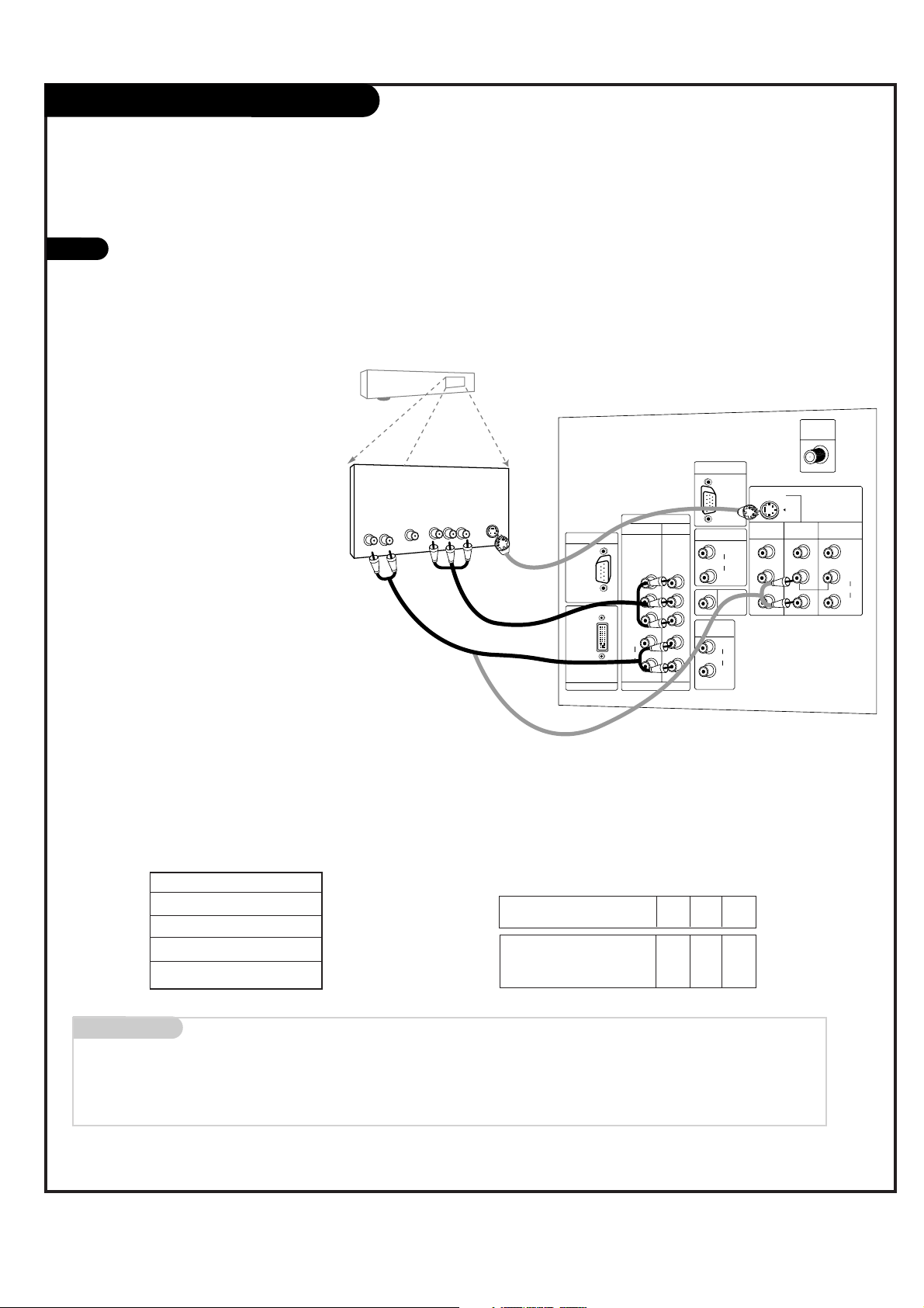
RGB-DTV/DVI-DTV Input
Find the audio and Y, PB, PR/RGB/DVI jacks
on the back of your DBS receiver and connect them following the instructions provided with your equipment.
Connect these cables to your TV as shown.
1
2
The DTV shows the sharpest picture in 720p mode.
Select RGB-DTV Source and press ENTER. Use UP/DOWN arrows to
select the desired options (H-Position/ V-Position/Phase) and then
use LEFT/RIGHT arrows to make appropriate adjustments.
Audio
L R
Component Out
Y Pb Pr
Dolby Digital
Out
DVI INPUT
PC/DTV
(XGA/
480p/
720p/
1080i)
UPGRADE PORT
INPUT2 INPUT1
P
R
PB
Y
(R)
(L)
AUDIO
DTV/DVD
(480i/
480p/
720p/
1080i)
(480i/
480p/
720p/
1080i)
COMPONENT
AUDIO
CENTER
MODE IN
DVI INPUT
PC/DTV
(XGA/
480p/
720p/
1080i)
PC/DTV
(XGA/
480p/
720p/
1080i)
RGB INPUT
UPGRADE PORT
RGB/DVI INPUT
(R)
(L)
AUDIO
(R)
(L)
AUDIO
VARIABLE
AUDIO OUT
COMPONENT
INPUT2 INPUT1
P
R
PB
Y
(R)
(L)
AUDIO
DTV /DVD
(480i/
480p/
720p/
1080i)
(480i/
480p/
720p/
1080i)
Audio
L R
Dolby Digital
Out
HD-SET TOP
1920x1080i
1280x720P
720x480P
RGB-DTV/DVI-DTV Input
Signal
480i
480p
720p
1080i
Component1
Yes
Yes
Yes
Yes
Component2
Yes
Yes
Yes
Yes
RGB/DVI-DTV
No
Yes
Yes
Yes
This TV supports HDCP (High-bandwidth Digital Content
Protection) protocol for DVI-DTV (480p, 720p, 1080i) mode.
DBS Receiver
DBS Receiver
A/V Cables
Not included
with TV
A/V Cables
Not included
with TV
In RGB-DTV mode, H-Position/ V-Position/Phase are not adjustable if
you choose either the POP or Twin picture modes.
or
W
W
W
W
PAGE 15
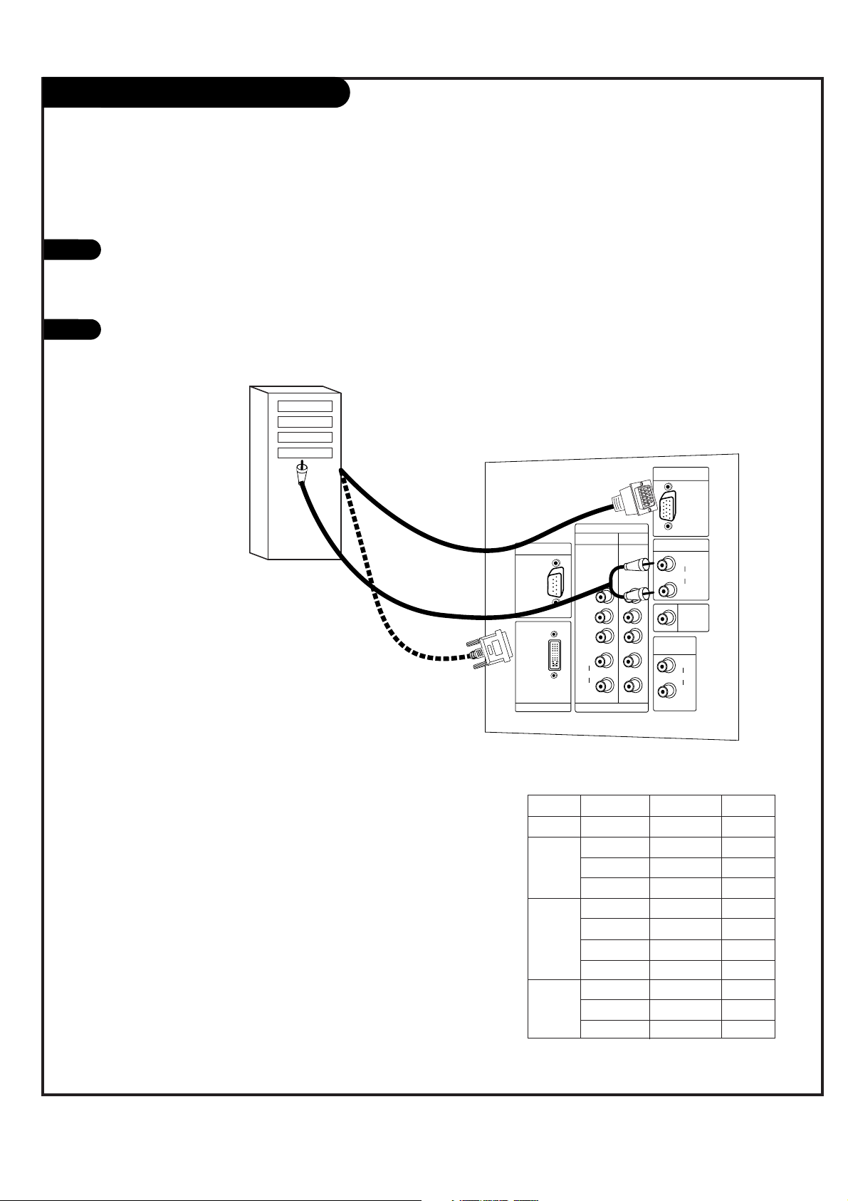
RGB-PC/DVI-PC Input
Find the audio and RGB or DVI jacks on the
back of your PC and then connect them following the instructions provided with your
equipment.
Connect these cables to your TV as shown.
1
2
Synchronization input form: Signals are separate.
In DVI-PC mode, adjustments are only Vertical size,
and Horizontal size.
AUDIO
CENTER
MODE IN
DVI INPUT
PC/DTV
(XGA/
480p/
720p/
1080i)
PC/DTV
(XGA/
480p/
720p/
1080i)
RGB INPUT
UPGRADE PORT
RGB/DVI INPUT
(R)
(L)
AUDIO
(R)
(L)
AUDIO
VARIABLE
AUDIO OUT
COMPONENT
INPUT2 INPUT1
P
R
PB
Y
(R)
(L)
AUDIO
DTV/DVD
(480i/
480p/
720p/
1080i)
(480i/
480p/
720p/
1080i)
Select RGB-PC Source and press ENTER. Use UP/DOWN arrows to
select the desired options (H-Position/V-Position/H-Size/VSize/Phase) and then use LEFT/RIGHT arrow to make appropriate
adjustments.
-
Horizontal position, Vertical position, Horizontal size, and Vertical
size: Based on the input mode (resolution), the adjustment
ranges may change.
-
PHASE: Removes any horizontal noise and clears up or sharpens
the character images. Adjustment range is -15 ~ + 15.
Computer
In RGB-PC/DVI-PC modes, for POP or Twin screen, HPosition/V-Position/H-Size/V-Size/Phase are not
adjustable.
W
W
W
W
RGB-PC/DVI-PC Input
MODE Resolution Horizontal Vertical
Text
640x350 31.5KHz 70Hz
640x480 31.5KHz 60Hz
VGA
640x480 37.9KHz 72Hz
640x480 37.5KHz 75Hz
800x600 35.2KHz 56Hz
SVGA
800x600 37.9KHz 60Hz
800x600 48.1KHz 72Hz
800x600 46.9KHz 75Hz
1024x768 48.4KHz 60Hz
XGA
1024x768 56.5KHz 70Hz
1024x768 68.7KHz 85Hz
PAGE 16
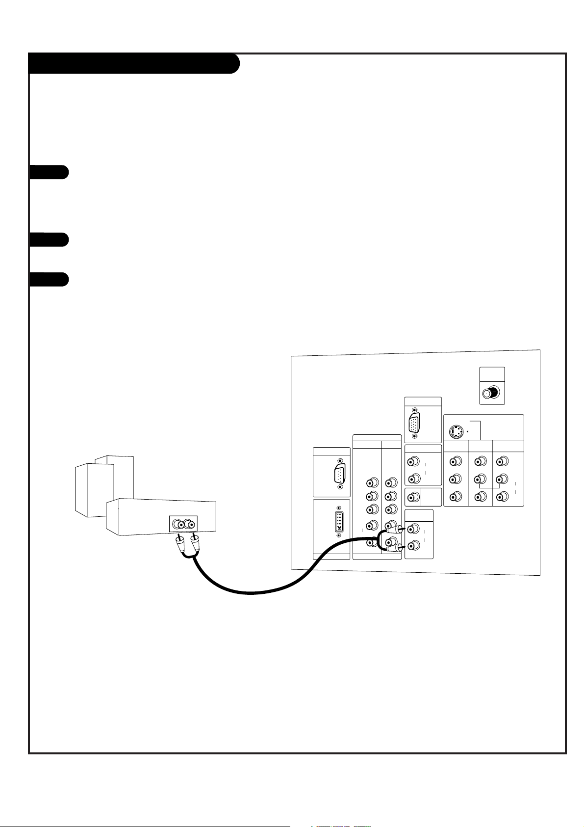
External Stereo Connections
1
2
Locate both Variable Audio Out
jacks on the back of your TV and
the Left/Right audio input jacks
on the back of your stereo's
amplifier.
Connect these jacks, making sure
that they are connected correctly.
(red=Right, white=Left.)
Adjust the sound on your stereo,
according to directions provided
with the amplifier.
3
Connect Left/Right Variable Audio Output to an external Audio Amplifier System.
AUDIO
CENTER
MODE IN
DVI INPUT
PC/DTV
(XGA/
480p/
720p/
1080i)
PC/DTV
(XGA/
480p/
720p/
1080i)
RGB INPUT
UPGRADE PORT
RGB/DVI INPUT
(R)
(L)
AUDIO
(R)
(L)
AUDIO
VARIABLE
AUDIO OUT
MONITOR
OUT
VIDEO
INPUT 2
VIDEO
INPUT 1
(R)
(L)
AUDIO
VIDEO
MONO
+75 Ω
ANT IN
COMPONENT
INPUT2 INPUT1
P
R
PB
Y
(R)
(L)
AUDIO
DTV/DVD
(480i/
480p/
720p/
1080i)
(480i/
480p/
720p/
1080i)
S-VIDEO
Analog stereo amplifier
A/V cables
not included
with TV
PAGE 17
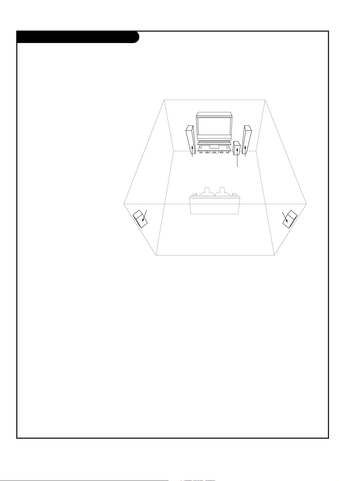
Home Theater: Speaker Layout
sub-woofer
right
speaker
left
speaker
surround
sound
speaker
surround
sound
speaker
This is a typical speaker layout.
Any number of other speaker setups
are possible, and some changes may
be needed to maximize your sound.
However, a Dolby Digital Receiver is
required to hear 5.1 channel audio.
Left and right speakers on each
side of the TV enhance separation.
The TV's sound optional hookup
“center mode in,” makes the dialog
sound as though it’s coming directly
from the TV. The rear surround
sound speakers provide
the majority of other sounds, like
those from special effects in movies.
Your sub-woofer generates ultra-low
frequency sound, for rumbling
low-end audio.
Sound is affected by
speaker placement, so
make sure nothing is in
front of the speakers, and
that they are aimed in
appropriate directions.
You have the option of
turning the TV speakers on
or off.
W
W
 Loading...