

Page 1

Test Report No.: GETEC-E3-05-033
FCC Class B Certification
APPENDIX H
: USER’S MANUAL
EUT Type: 44” DLP Projection TV
FCC ID: BEJ44SZ8DUA
Page 2

Installation and Operating Guide | Warranty
Model Numbers | Z44SZ80/Z52SZ80 | DLP PROJECTION
© Copyright 2005, LG Electronics USA, Inc.
Page 3
WARNING
RISK OF ELECTRIC SHOCK
DO NOT OPEN
/CAUTION
Warning/Caution
W
arning/Caution
W
arning/Caution
WARNING/CAUTION:
TO REDUCE THE RISK OF ELECTRIC SHOCK DO NOT REMOVE COVER (OR BACK). NO USER
SERVICEABLE PARTS INSIDE. REFER TO QUALIFIED SERVICE PERSONNEL.
The lightning flash with arrowhead symbol, within an equilateral triangle, is intended to alert the user to
the presence of uninsulated “dangerous voltage” within the product’s enclosure that may be of sufficient magnitude to constitute a risk of electric shock to persons.
The exclamation point within an equilateral triangle is intended to alert the user to the presence of
important operating and maintenance (servicing) instructions in the literature accompanying the appliance.
WARNING/CAUTION:
TO PREVENT FIRE OR SHOCK HAZARDS, DO NOT EXPOSE THIS PRODUCT TO RAIN OR MOISTURE.
POWER CORD POLARIZATION:
CAUTION: TO PREVENT ELECTRIC SHOCK, MATCH WIDE BLADE OF PLUG TO WIDE SLOT, FULLY
INSERT.
ATTENTION: POUR ÉVITER LES CHOCS ÉLECTRIQUES, INTRODUIRE LA LAME LA PLUS LARGE
DE LA FICHE DANS LA BORNE CORRESPONDANTE DE LA PRISE ET POUSSER JUSQU’AU FOND.
NOTE TO CABLE/TV INSTALLER:
This reminder is provided to call the CATV system installer’s attention to Article 820-40 of the National
Electric Code (U.S.A.). The code provides guidelines for proper grounding and, in particular, specifies that
the cable ground shall be connected to the grounding system of the building, as close to the point of the
cable entry as practical.
REGULATORY INFORMATION:
This equipment has been tested and found to comply with the limits for a Class B digital device, pursuant to Part
15 of the FCC Rules. These limits are designed to provide reasonable protection against harmful interference in
a residential installation. This equipment generates, uses and can radiate radio frequency energy and, if not
installed and used in accordance with the instructions, may cause harmful interference to radio communications.
However, there is no guarantee that interference will not occur in a particular installation. If this equipment does
cause harmful interference to radio or television reception, which can be determined by turning the equipment off
and on, the user is encouraged to try to correct the interference by one or more of the following measures:
- Reorient or relocate the receiving antenna.
- Increase the separation between the equipment and receiver.
- Connect the equipment into an outlet on a circuit different from that to which the receiver is connected.
- Consult the dealer or an experienced radio/TV technician for help.
Any changes or modifications not expressly approved by the party responsible for compliance could void the
user’s authority to operate the equipment.
CAUTION:
Do not attempt to modify this product in any way without written authorization from LG Electronics. Unauthorized modification could void the user’s authority to operate this product.
COMPLIANCE:
The responsible party for this product’s compliance is:
Zenith Electronics Corporation
1-201-816-2000
Marked and Distributed in the United States by LG Electronics U.S.A., Inc.
1000 Sylvan Avenue, Englewood Cliffs, NJ 07632
http://www.zenith.com
2 DLP Projection TV
Page 4
Safety Instructions
PORTABLE CART WARNING
Safety Instructions
Safety Instructions
IMPORTANT SAFETY INSTRUCTIONS
Important safety instructions shall be provided with each apparatus. This information shall be given in a separate booklet or
sheet, or be located before any operating instructions in an instruction for installation for use and supplied with the apparatus. This information shall be given in a language acceptable to the country where the apparatus is intended to be used. The
important safety instructions shall be entitled “Important Safety Instructions”. The following safety instructions shall be included where applicable, and, when used, shall be verbatim as follows. Additional safety information may be included by adding
statements after the end of the following safety instruction list. At the manufacturer’s option, a picture or drawing that illustrates the intent of a specific safety instruction may be placed immediately adjacent to that safety instruction :
1. Read these instructions.
2. Keep these instructions.
3. Heed all warnings.
4. Follow all instructions.
5. Do not use this apparatus near water.
6. Clean only with dry cloth.
7. Do not block any ventilation openings. Install in accordance with the manufacturer’s instructions.
8. Do not install near any heat sources such as radiators, heat registers, stoves, or other apparatus (including ampli-
fiers)that produce heat.
9. Do not defeat the safety purpose of the polarized or grounding-type plug. A polarized plug has two blades with
one wider than the other. A grounding type plug has two blades and a third grounding prong, The wide blade or the
third prong are provided for your safety. If the provided plug does not fit into your outlet, consult an electrician for
replacement of the obsolete outlet.
10. Protect the power cord from being walked on or pinched particularly at plugs, convenience receptacles, and the
point where they exit from the apparatus.
11. Only use attachments/accessories specified by the manufacturer.
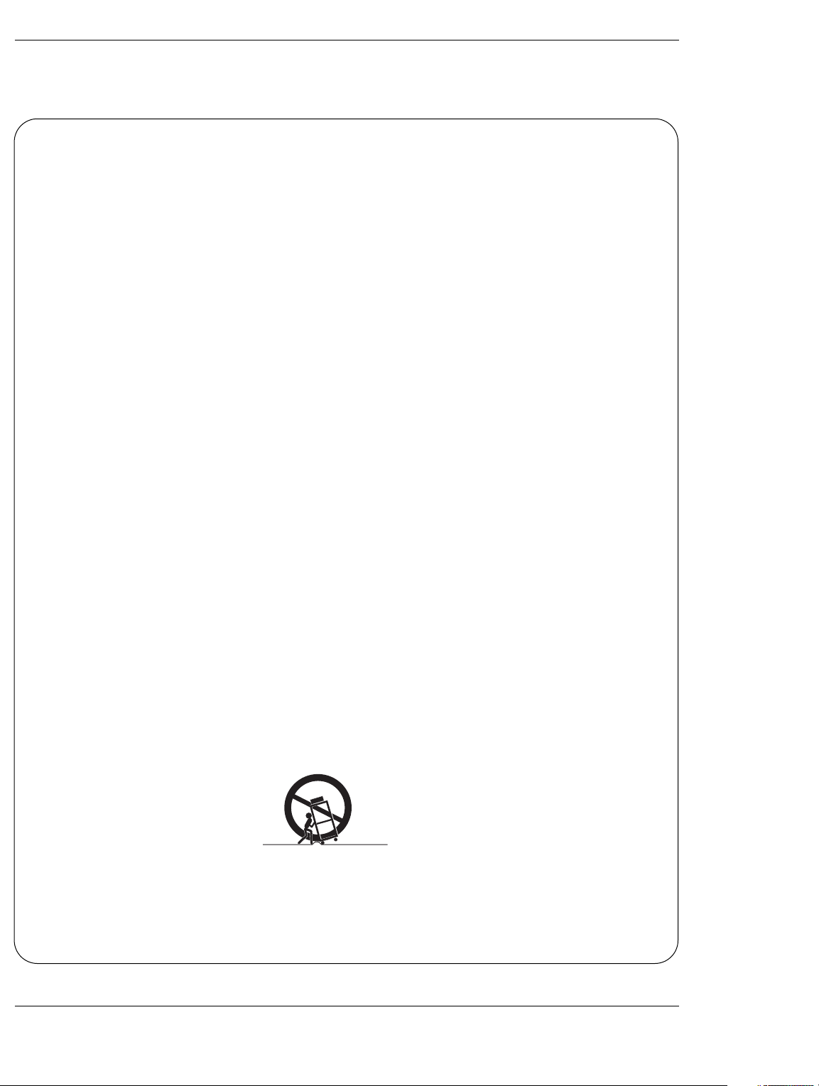
12. Use only with the cart, stand, tripod, bracket, or table specified by the manufacturer, or sold with the apparatus.
When a cart is used, use caution when moving the cart/apparatus combination to avoid injury from tip-over.
Owner’s Manual 3
Page 5

Safety Instructions
13. Unplug this apparatus during lightning storms or when unused for long periods of time.
14. Refer all servicing to qualified service personnel. Servicing is required when the apparatus has been damaged
in any way, such as power-supply cord or plug is damaged, liquid has been spilled or objects have fallen into
the apparatus, the apparatus has exposed to rain or moisture, does not operate normally, or has been dropped.
15. CAUTION concerning the Power Cord :
Most appliances recommend they be placed upon a dedicated circuit; that
is, a single outlet circuit which powers only that appliance and has no
additional outlets or branch circuits. Check the specification page of
this owner's manual to be certain.
Do not overload wall outlets. Overloaded wall outlets, loose or damaged
wall outlets, extension cords, frayed power cords, or damaged or
cracked wire insulation are dangerous. Any of these conditions could
result in electric shock or fire. Periodically examine the cord of your
appliance, and if its appearance indicates damage or deterioration,
unplug it, discontinue use of the appliance, and have the cord replaced
with an exact replacement part by an authorized servicer.
Protect the power cord from physical or mechanical abuse, such as being
twisted, kinked, pinched, closed in a door, or walked upon. Pay
particular attention to plugs, wall outlets, and the point where the
cord exits the appliance.
16. Outdoor Use Marking :
WARNING - To Reduce The Risk Of Fire Or Electric Shock, Do Not Expose This Appliance To Rain Or Moisture.
17. Wet Location :
Apparatus shall not be exposed to dripping or splashing and no objects filled with liquids, such as vases, shall
be placed on the apparatus.
4 DLP Projection TV
Page 6

Contents
POWER
(북미)
POWER
(북미)
방
송
뉴
방
입력
전원
제품선택
TN-60/50PY20
TN-42PX40X(한국) DN-42PX40X(한국)
Contents
Contents
Warnings/Caution . . . . . . . . . . . . . . . . . . . . . . . . . . . . . . .2
Digital Cable Compatibility . . . . . . . . . . . . . . . . . . . . . . . . .3
Safety Instructions . . . . . . . . . . . . . . . . . . . . . . . . . . . . .4~5
Introduction
Controls . . . . . . . . . . . . . . . . . . . . . . . . . . . . . . .7
Connection Options . . . . . . . . . . . . . . . . . . . .8~9
Remote Control Key Functions . . . . . . . . . .10~11
Installation
External Equipment Connections . . . . . . . . . .12~30
Antenna or Cable Connection . . . . . . . . . . . . . .12
VCR Setup . . . . . . . . . . . . . . . . . . . . . . . . . . .13
External A/V Source Setup . . . . . . . . . . . . . . . .14
DVD Setup . . . . . . . . . . . . . . . . . . . . . . . . . . . .14
CableCARD
HDSTB Setup . . . . . . . . . . . . . . . . . . . . . . . . . .15
Monitor Out Setup . . . . . . . . . . . . . . . . . . . . . .15
PC Setup . . . . . . . . . . . . . . . . . . . . . . . . . . . . .16
Digital Audio Output . . . . . . . . . . . . . . . . . . . . .17
External Stereo . . . . . . . . . . . . . . . . . . . . . . . . .17
HDMI . . . . . . . . . . . . . . . . . . . . . . . . . . . . .18~20
TV Guide On Screen Setup . . . . . . . . . . . . . .21~30
TM
Setup . . . . . . . . . . . . . . . . . . . . .15
IEEE 1394 Functions . . . . . . . . . . . . . . . . . . . . . .31-37
TV Guide On ScreenTMSystem . . . . . . . . . . . . . .38-56
Operation
Turning the TV On . . . . . . . . . . . . . . . . . . . . . .57
TV Setup
On-screen Menus Language Selection . . . . . . .58
Setup Menu Options
EZ Scan (Channel Search) . . . . . . . . . . . . . . . .59
Manual Scan . . . . . . . . . . . . . . . . . . . . . . . . . .59
Channel Edit . . . . . . . . . . . . . . . . . . . . . . . . . . .60
DTV Signal Strength . . . . . . . . . . . . . . . . . . . . .60
Channel Label Setup . . . . . . . . . . . . . . . . . . . .61
Main Picture Source Selection . . . . . . . . . . . . .61
Input Label . . . . . . . . . . . . . . . . . . . . . . . . . . . .61
Video Menu Options
EZ Picture . . . . . . . . . . . . . . . . . . . . . . . . . . . .62
Manual Picture Control (Custom Option) . . . . . .62
Color Temperature Control . . . . . . . . . . . . . . . .62
Video Reset . . . . . . . . . . . . . . . . . . . . . . . . . . .62
Audio Menu Options
Audio Language . . . . . . . . . . . . . . . . . . . . . . . .63
EZ SoundRite / EZ Sound . . . . . . . . . . . . . . . . .63
Manual Sound Control (Custom Option) . . . . . .63
Front Surround . . . . . . . . . . . . . . . . . . . . . . . . .64
TV Speakers On/Off Setup . . . . . . . . . . . . . . . .64
Stereo/SAP Broadcasts Setup . . . . . . . . . . . . . .64
Time Menu Options
Auto Clock Setup . . . . . . . . . . . . . . . . . . . . . . .65
Manual Clock Setup . . . . . . . . . . . . . . . . . . . . .65
On/Off Timer Setup . . . . . . . . . . . . . . . . . . . . .65
Sleep Timer / Auto Off . . . . . . . . . . . . . . . . . . . .66
Option Menu Options
Aspect Ratio Control . . . . . . . . . . . . . . . . . . . . .67
Cinema 3:2 Mode Setup . . . . . . . . . . . . . . . . . .67
Caption . . . . . . . . . . . . . . . . . . . . . . . . . . . . . . .68
Caption / Text . . . . . . . . . . . . . . . . . . . . . . . . . .68
Caption Option . . . . . . . . . . . . . . . . . . . . . . . . .69
EZ Demo . . . . . . . . . . . . . . . . . . . . . . . . . . . . .69
Lock Menu Options
Parental Lock Setup . . . . . . . . . . . . . . . . . . . . .71
CableCARDTMFunction
Cable menu options . . . . . . . . . . . . . . . . . . . . .72
Scrambled channel . . . . . . . . . . . . . . . . . . . . . .72
Cable Channel List . . . . . . . . . . . . . . . . . . . . . .73
Emergency Alert Message . . . . . . . . . . . . . . . .73
Notes on Memory Card . . . . . . . . . . . . . . . .74~77
JEPG File Viewing Options . . . . . . . . . . . . .78~82
MP3 File Playing Operation . . . . . . . . . . . . .83~86
Remote Control
PIP (Picture-in-Picture)/POP/Twin Picture . . . ..87
Watching PIP/POP/Twin Picture . . . . . . . . . . . ..87
Selecting an Input Signal Source for PIP/Twin Picture
Swapping the PIP/Twin Picture . . . . . . . . . . . . .87
TV Program Selection for PIP . . . . . . . . . . . . . .87
Moving the PIP sub picture . . . . . . . . . . . . . . . .88
Adjusting Main and Sub Picture Sizes for Twin Picture . .88
POP (Picture-out-of-Picture: Channel Scan) . . .88
APM(Adaptive Picture Mode) . . . . . . . . . . . . . .89
Brief Info.. . . . . . . . . . . . . . . . . . . . . . . . . . . . . .90
EZ Mute . . . . . . . . . . . . . . . . . . . . . . . . . . . . . .91
Freeze & Magnify . . . . . . . . . . . . . . . . . . . . . . .91
Screen Setup for PC mode . . . . . . . . . . . . . . . .92
Programming the Remote . . . . . . . . . . . . . . . . . . . . . .93
Programming Codes . . . . . . . . . . . . . . . . . . . . . . .94~95
Troubleshooting Checklist . . . . . . . . . . . . . . . . . . .96~98
Maintenance . . . . . . . . . . . . . . . . . . . . . . . . . . . . . . . . .99
Product Specifications . . . . . . . . . . . . . . . . . . . . . . . .100
Warranty . . . . . . . . . . . . . . . . . . . . . . . . . . . . . . . .103~104
. .87
After reading this manual, keep it handy for future reference.
Owner’s Manual 5
Page 7
Introduction
POWER
MENU ENTER VOL CH
Introduction
Introduction
Controls
Controls
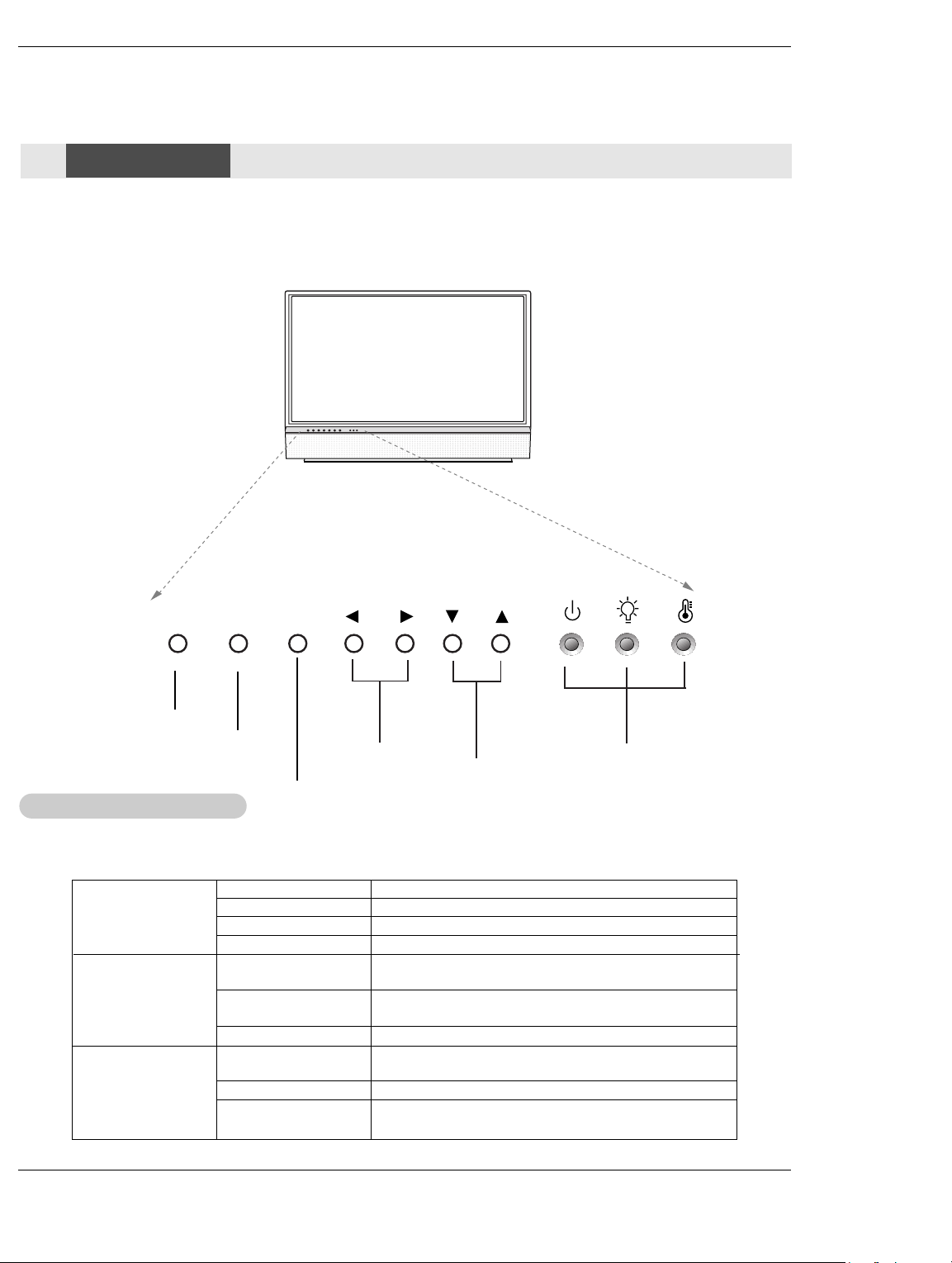
- This is a simplified representation of a front panel.
- Here shown may be somewhat different from your TV.
Front Panel Controls
Front Panel Controls
POWER Button
MENU Button
ENTER Button
Function Status Indicators
Function Status Indicators
- Lamp indicator, operation indicator, and temperature indicator located below the front panel controls, reveal the
operating status of the DLP projection TV.
Off Power cord is not connected.
Operation Indicator
Lamp Indicator
Temperature Indicator
6 DLP Projection TV
Red Power Cord is connected, TV is in standby mode.
Green TV turns on.
Orange (flashing) Preparing operation in standby mode.
Orange Projection lamp is reaching the end of its life and needs to
Red (flashing) There is a problem with the lamp or around it. Contact an
Green (flashing) The lamp cover is not closed.
Orange The projection TV is overheating. Check the blocked vents of
Red The projection TV shut down due to overheating.
Red (flashing) The projection TV shut down, check the cooling fan. Contact
your service center.
VOLUME (F,G)
Buttons
be replaced with a new lamp. Contact your service center.
authorized service center.
the projection TV and the accumulated dust in the dust filter.
CHANNEL (E, D)
Buttons
Operation Indicator/
Lamp Indicator/
Temperature Indicator
Page 8
PC/DTV
(XGA
/480p
/720p
/1080i)
S-VIDEO
PR
PB
Y
MONO
RGB INPUT
COMPONENT
INPUT2 INPUT1
DTV/DVD INPUT
RGB/DVI INPUT
(L)
(R)
AUDIO
(L)
(R)
AUDIO
VIDEO
(L)
(R)
AUDIO
(L)
(R)
AUDIO
MONITOR
OUT
INPUT2
INPUT1
DIGITAL AUDIO
OPTICAL INPUT1
(COMPONENT2)
DIGITAL AUDIO
OPTICAL INPUT2
(DVI)
DIGITAL AUDIO
OPTICAL OUTPUT
ANTENNA
HDMI1
/DVI
VARIABLE
AUDIO OUT
HDMI2
UPGRADE
PORT
CABLE
Connection Options
Connection Options
Back Connection Panel
Back Connection Panel
Introduction
DIGITAL AUDIO OPTICAL
OUTPUT
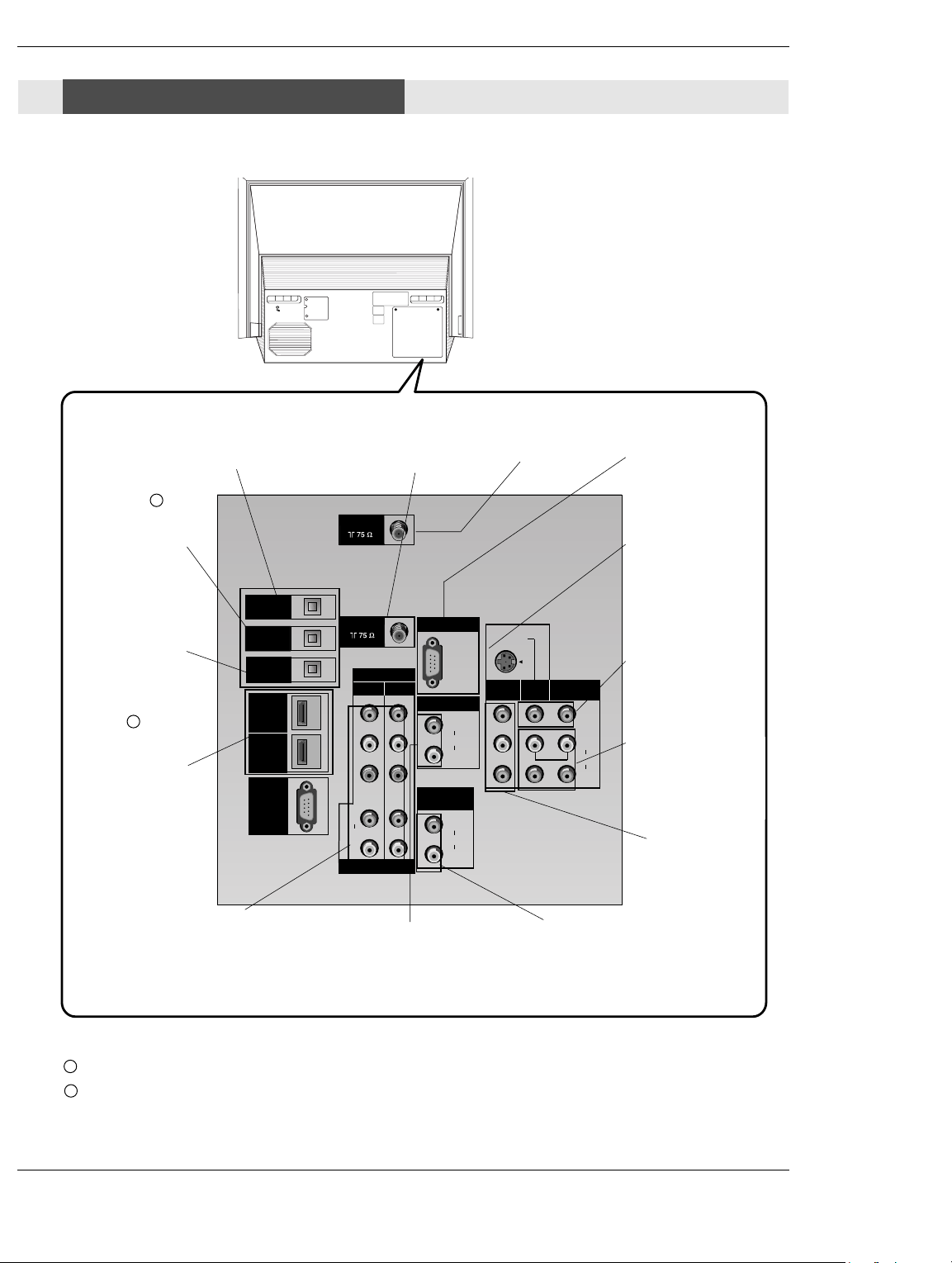
Used to connect either an external
amplifier, or add a sub-woofer to
your surround sound system if it has
a digital
audio optical input.
(Refer to )
1
DIGITAL AUDIO OPTICAL INPUT1(COMPONENT2)
Connect digital audio
from the equipment
connected to COMPONENT 2.
DIGITAL AUDIO OPTICAL INPUT2(DVI)
Connect digital audio
from the equipment
connected to
HDMI/DVI(VIDEO).
(Refer to )
HDMI1/DVI, HDMI 2
Connect a HDMI signal
to HDMI1/DVI or
HDMI2. Or connect a
DVI(Video) signal to
2
HDMI1/DVI.
COMPONENT INPUT 1-2
Connect a component
video/audio device to
these jacks. Refer to your
DVD manual for further
information.
CABLE Inputs
Connect cable signals to
the TV, either directly or
through your cable box.
RGB/DVI INPUT
Connect the monitor
output connector from
a PC to the appropriate input port.
ANTENNA Inputs
Connect antenna signals to the TV directly.
VARIABLE AUDIO OUT
Used to connect either an
external amplifier, or add a
sub-woofer to your surround
sound system.
RGB Input
Connect the TV output
connector from a
PC/DTV to the appropriate input port.
S-VIDEO In
A connection available with some highend equipment that
provides even better
picture quality for
Video 2.
VIDEO 1 or 2
Connects the video
signals from various
types of equipment.
Left/Right AUDIO
Used for stereo sound
from various types of
equipment.
MONITOR OUT
Connect a second TV or
Monitor.
Notes: In standby mode, these port will not work.
1
2
If the video is connected through HDMI-TO-HDMI cable, you don’t need to connect digital audio. This port
is used only when the video connected through DVI-TO-HDMI cable.
Owner’s Manual 7
Page 9
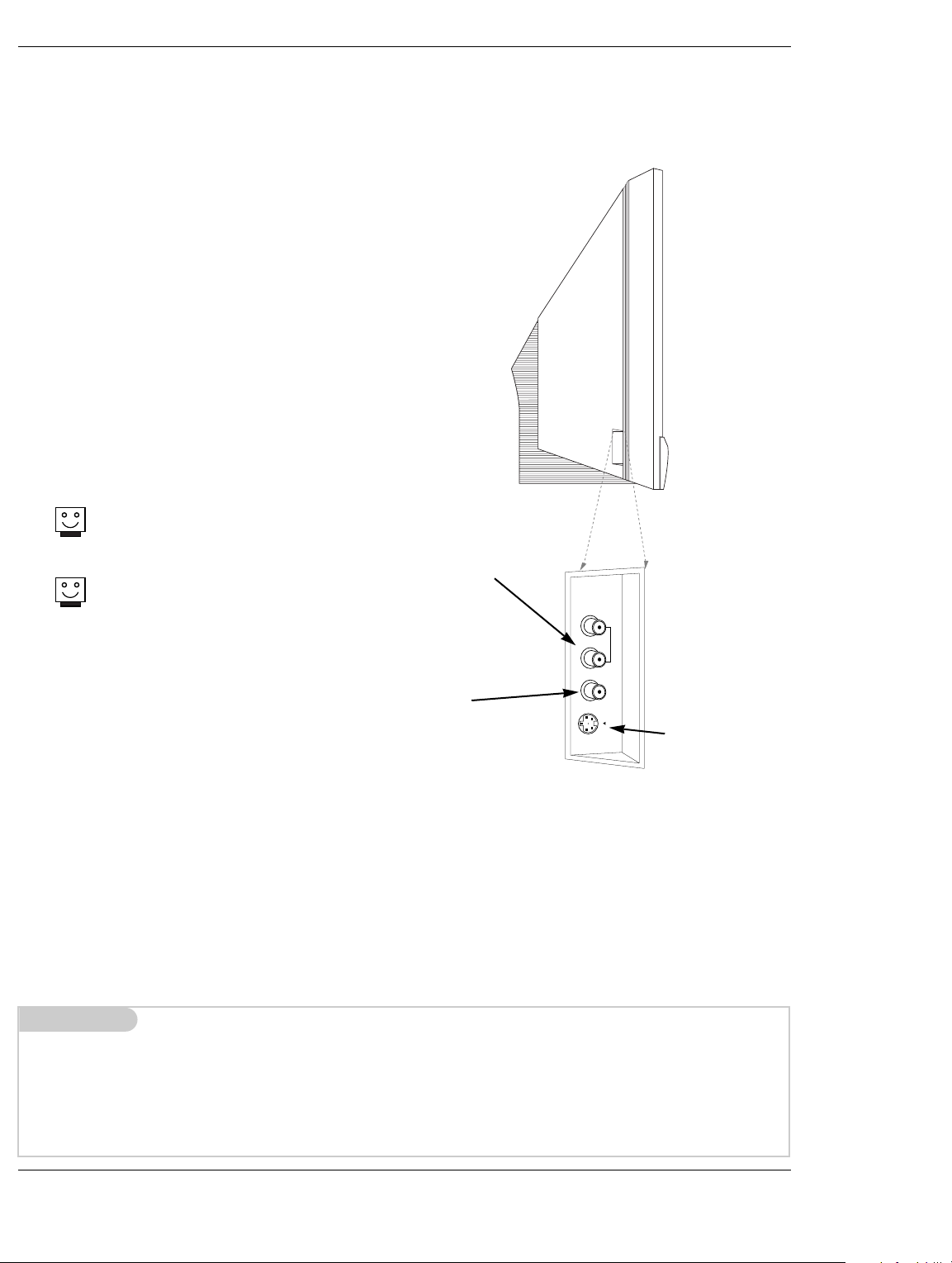
Introduction
Side A/V Panel
S-VIDEO
VIDEO
SIDE VIDEO
AUDIO
(R
)
(
L
)
/
M
O
N
O
There are four jacks on the left side on your projection TV
that make connecting Audio/Video devices like video
games and camcorders very simple.
The jacks are like those found on the back jack connection
panel. This means that most equipment that connects to
those types of jacks on the rear jackpack, may be connected to the front connection panel.
To use the side jacks as the signal source, select them
using Main Input menu as described on page 61. They will
be named “Front Video” in the Main Input menu.
Front Connection Panel
Front Connection Panel
If you input both Front Video and
S-Video, only the S-Video will
work.
If you’re connecting a video game
device, make sure to change the
picture settings with the EZ
Picture option in the Video menu
(see page 62).
Mini glossary
A/V CABLESAudio/Video cables. Three cable connector—Right audio (red), Left audio (white), and Video (yellow). A/V cables are
used for stereo playback of videocassettes and for higher quality picture and sound from other A/V devices.
A/V DEVICE Any device that produces video or sound (VCR, DVD, cable box, or television).
LEFT/RIGHT
AUDIO
Used for stereo
sound from various types of
equipment.
VIDEO
Connects the
video signals
from any piece of
equipment.
S-VIDEO
A connection
available on
some very highend equipment
that provides better picture quality
than video input.
8 DLP Projection TV
Page 10
1 2 3
4 5 6
7 8 9
0
TV
MODE
LIGHT
POWER
TV/VIDEO
INFO
SLEEP
VCR
CABLE
DVD
SAT
MUTE
SWAPPIPCH- PIPCH+
PIP
RATIO
RECORD
STOP
PAUSE
REW
PLAY
FF
MENU EXIT
CC FREEZE
PIP INPUT
VOL
CH
FAV
SAP
ADJUST
EZ SoundEZ Video
TV INPUT
SKIP
FLASHBK
+
-
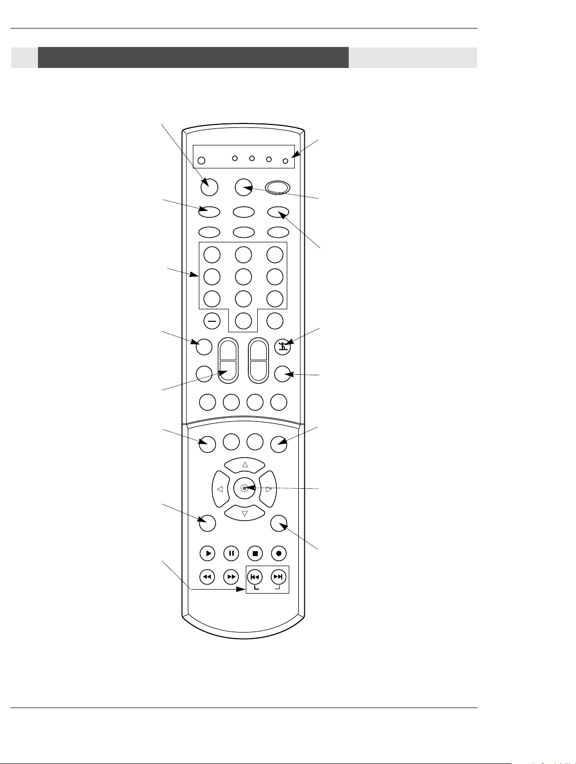
Remote Control Key Functions
Remote Control Key Functions
- When using the remote control, aim it at the remote control sensor on the TV.
Introduction
Selects the remote operating mode:
TV, VCR, Cable, DVD and Satellite.
Select other operating modes, for the
remote to control external devices.
Selects: Analog, Video1, Video2, Side
video, Component1-2, RGB, and DVI
For direct channel selection and
Switches the sound on or off.
NUMBER KEYPAD
programming functions.
TV/VIDEO
input sources.
Increases/decreases the sound level.
VOLUME UP/DOWN
MODE
MUTE
(Refer to
p.91)
INDICATOR LIGHTS
Show active remote mode
every time any button is
pressed.
LIGHT
Illuminates the remote control keys.
INFO
When you watch the TV, information displays on top of the screen. Not available
in Component 1-2, RGB, HDMI1/DVI and
HDMI2 mode.(Refer to p.90)
FAV
Scrolls the Favorite channels.
ADJUST
Adjusts screen position, size, and phase
in PC mode.
Changes the screen format or aspect
Playing DVDs: Selects movie chapters.
Brings up the main menu to the
Playing CDs: Selects songs.
RATIO
ratio.
MENU
screen.
SKIP
PIP INPUT
Selects the input source for the sub
picture.
ENTER
When in the menu system and other
on-screen displays, selects highlighted
options.
EXIT
Clears all on-screen displays and returns
to TV viewing from any menu.
Owner’s Manual 9
Page 11
Introduction
1 2 3
4 5 6
7 8 9
0
TV
MODE
LIGHT
POWER
TV/VIDEO
INFO
SLEEP
VCR
CABLE
DVD
SAT
MUTE
SWAPPIPCH- PIPCH+
PIP
RATIO
RECORD
STOP
PAUSE
REW
PLAY
FF
MENU EXIT
CC FREEZE
PIP INPUT
VOL
CH
FAV
SAP
ADJUST
EZ SoundEZ Video
TV INPUT
SKIP
FLASHBK
+
-
back of
remote
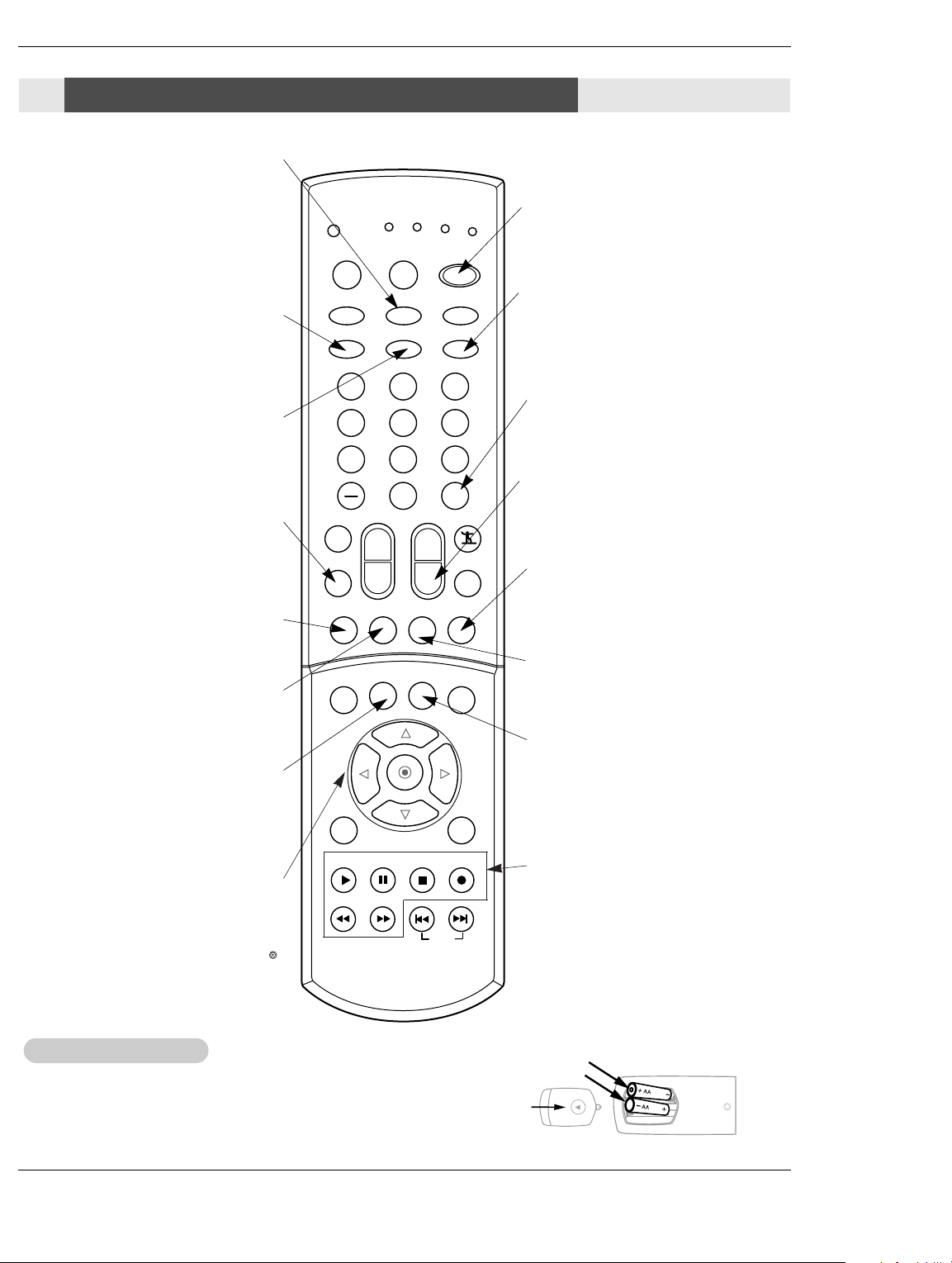
Remote Control Key Functions
Remote Control Key Functions
• Rotates the input mode between Antenna
TV INPUT
and Cable.
• Video 1-2, Front Video, Component 1-2,
RGB-DTV (or RGB-PC), HDMI1/DVI,
HDMI2
and IEEE1394 input sources, TV will return
to the last TV channel.
EZ Video
Adjusts the factory preset picture
depending on the viewing environ-
ment.
Selects the sound appropriate for
EZ Sound
the program's character.
Selects MTS sound: Mono, Stereo, and
SAP in Analog mode. Change the audio
SAP
language in DTV mode.
Toggles between PIP, POP (Picture-out-
of-Picture) and Twin picture mode.
PIP
PIPCH-
CC
able on program.
Changes to next lower PIP channel
Selects a closed caption mode for dis-
playing captioning information if avail-
POWER
Turns your TV or any other programmed
equipment on or off, depending on mode.
SLEEP
FLASHBK
Tunes to the last channel viewed.
CHANNEL UP/DOWN
Scrolls through available channels in
EZ Scan memory.
SWAP
Switches the picture from PIP, POP, or
twin picture to the main screen.
PIPCH+
Changes to next higher PIP channel.
FREEZE
Captures and freezes the currentlyviewed main picture in PIP mode.
Allows you to navigate the on-screen
THUMBSTICK
menus and to adjust the system settings
and preferences, by moving to an option
D
with
F G
and selecting the highlighted
E
Installing Batteries
Installing Batteries
• Open the battery compartment cover on the back side and install the batteries
option with .
matching correct polarity (+ with +, - with -).
• Install two 1.5V AA batteries. Don’t mix old or used batteries with new ones.
Close cover.
10 DLP Projection TV
RECORD, PAUSE, REW, FFWD,
PLAY, STOP
Control the functions on your VCR.
Page 12
CABLE
Installation
Installation
External Equipment Connections
External Equipment Connections
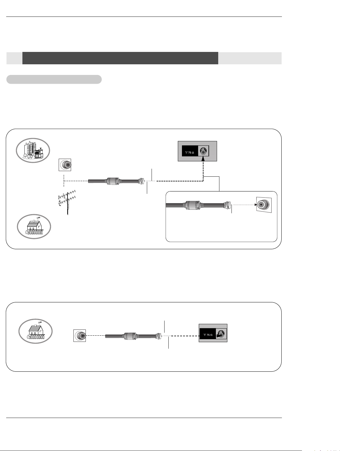
Antenna or Cable Connection
Antenna or Cable Connection
1. Analog and Digital TV signals provided on antenna
- Wall Antenna Socket or Outdoor Antenna without a Cable Box Connections
- For optimum picture quality, adjust antenna direction if needed.
Multi-family Dwellings/Apartments
(Connect to wall antenna socket)
Wall Antenna
Socket
Bronze Wire
RF Coaxial Wire (75 ohm)
Installation
ANTENNA
VHF Antenna
UHF Antenna
Outdoor
Antenna
Single-family Dwellings /Houses
(Connect to wall jack for outdoor antenna)
2. Analog and Digital TV signals provided on cable
Cable TV Wall
Jack
Turn clockwise to tighten.
RF Coaxial Wire (75 ohm)
Bronze Wire
Be careful not to bend the bronze wire when
connecting the antenna.
Turn clockwise to tighten.
Bronze Wire
Owner’s Manual 11
Page 13
ANTENNA
ANTENNA
CABLE
PC/DTV
(XGA
/480p
/720p
/1080i)
S-VIDEO
PR
PB
Y
MONO
RGB INPUT
COMPONENT
INPUT2 INPUT1
DTV/DVD INPUT
RGB/DVI INPUT
(L)
(R)
AUDIO
(L)
(R)
AUDIO
VIDEO
(L)
(R)
AUDIO
(L)
(R)
AUDIO
MONITOR
OUT
INPUT2
INPUT1
DIGITAL AUDIO
OPTICAL INPUT1
(COMPONENT2)
DIGITAL AUDIO
OPTICAL INPUT2
(DVI)
DIGITAL AUDIO
OPTICAL OUTPUT
ANTENNA
HDMI1
/DVI
VARIABLE
AUDIO OUT
HDMI2
UPGRADE
PORT
CABLE
S-VIDEO
OUT
IN
(R) AUDIO (L)VIDEO
34
OUTPUT
SWITCH
ANT OUT
ANT IN
Installation
3. Analog and Digital TV signals provided on cable and antenna
Antenna
Bronze Wire
RF Coaxial Wire (75 ohm)
Cable TV Wall
Jack
RF Coaxial Wire (75 ohm)
Turn clockwise to tighten.
Bronze Wire
• To improve the picture quality in a poor signal area,
please purchase a signal amplifier and install properly.
• If the antenna needs to be split for two TV’s, install a “2-
Way Signal Splitter” in the connections.
• If the antenna is not installed properly, contact your deal-
Signal
Amplifier
er for assistance.
Note: The TV will let you know when the TV(analog antenna), DTV(digital antenna), CATV(analog cable) and CADTV(digital
cable) channel scans are complete.
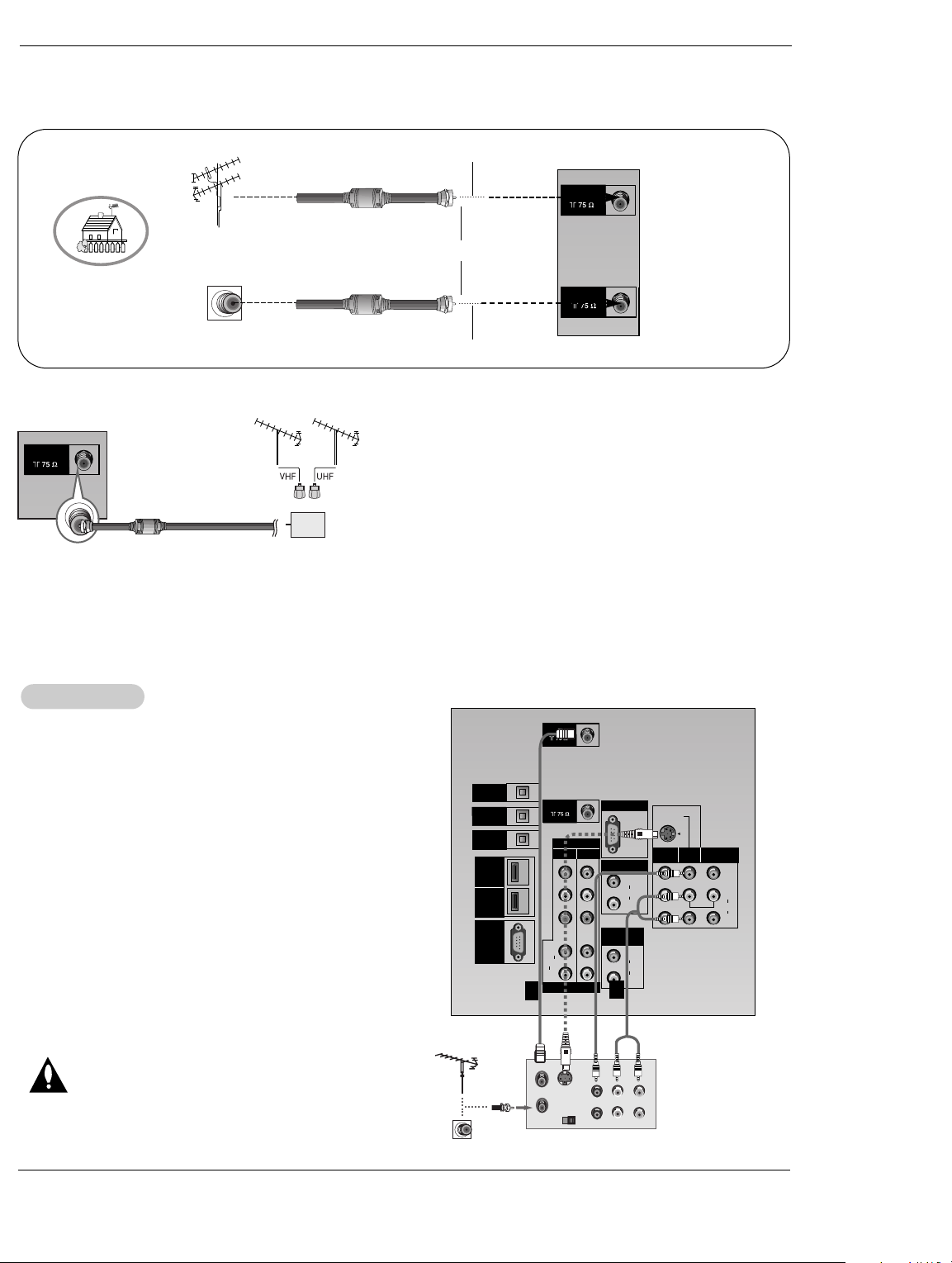
VCR Setup
VCR Setup
Connection Option 1
Set VCR output switch to channel 3 or 4 and then tune the
TV to the same channel number.
Connection Option 2
1. Connect the audio and video cables from the VCR's output
jacks to the TV input jacks, as shown in the figure.
When connecting the TV to VCR, match the jack colors
(Video = yellow, Audio Left = white, and Audio Right = red).
If you connect an S-VIDEO output from VCR to the S-VIDEO
input, the picture quality is improved; compared to connecting
only the Video input.
2. Insert a video tape into the VCR and press PLAY on the
VCR. (Refer to the VCR owner’s manual.)
3. Select the input source with using the TV/VIDEO button on
the remote control. Note that this TV finds the connected
input sources automatically for Video, Front Video and
Component 1-2. It is presumed that RGB, HDMI1/DVI and
HDMI2 sources are connected.
Do not connect to both Video and S-Video at the
same time. In the event that you connect both Video
and the S-Video cables, only the S-Video will work.)
1
2
VCR Rear
Owner’s Manual 12
Page 14
Installation
PC/DTV
(XGA
/480p
/720p
/1080i)
S-VIDEO
PR
PB
Y
MONO
RGB INPUT
COMPONENT
INPUT2 INPUT1
DTV/DVD INPUT
RGB/DVI INPUT
(L)
(R)
AUDIO
(L)
(R)
AUDIO
VIDEO
(L)
(R)
AUDIO
(L)
(R)
AUDIO
MONITOR
OUT
INPUT2
INPUT1
DIGITAL AUDIO
OPTICAL INPUT1
(COMPONENT2)
DIGITAL AUDIO
OPTICAL INPUT2
(DVI)
DIGITAL AUDIO
OPTICAL OUTPUT
ANTENNA
HDMI1
/DVI
VARIABLE
AUDIO OUT
HDMI2
UPGRADE
PORT
CABLE
(R) AUDIO (L)
S-VIDEO
B
R
(R) AUDIO (L)
DIGITAL AUDIO
OPTICAL
PC/DTV
(XGA
/480p
/720p
/1080i)
S-VIDEO
MONO
RGB INPUT
RGB/DVI INPUT
(L)
(R)
AUDIO
(L)
(R)
AUDIO
VIDEO
(L)
(R)
AUDIO
MONITOR
OUT
INPUT2
INPUT1
VARIABLE
AUDIO OUT
(L)
(R)
VIDEO
RL
AUDIO VIDEO
External
External
A/V Source Setup
A/V Source Setup
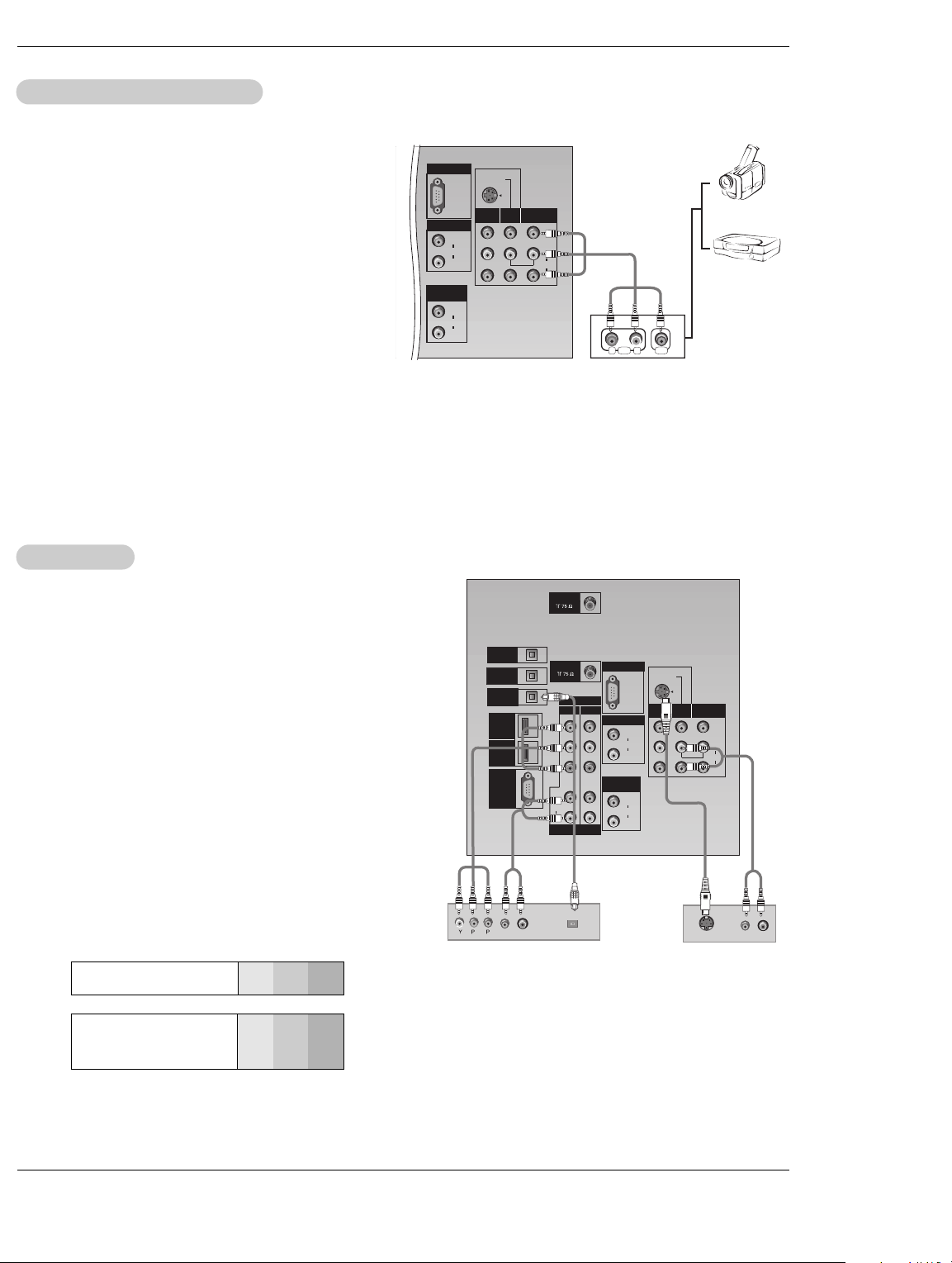
How to connect
Connect the audio and video cables from the external equipment's output jacks to the TV input jacks, as shown in the
figure.
When connecting the TV to external equipment, match the
jack colors (Video = yellow, Audio Left = white, and Audio
Right = red).
How to use
1. Select the input source by using the TV/VIDEO button on
the remote control. Note that this TV finds the connected
input sources automatically for Video 1-2 and Component 1-
2. It is presumed that RGB, HDMI1/DVI and HDMI2 sources
are connected.
2. Operate the corresponding external equipment. For connection instructions for operating the TV Guide On Screen system, see page 21~22.
DVD Setup
DVD Setup
Camcorder
Video Game
Set
How to connect
1. Connect the DVD video outputs (Y, P
NENT (Y, PB
, PR) INPUT jacks on the TV and connect the
DVD audio outputs to the AUDIO INPUT jacks on the TV, as
shown in the figure.
2. If your DVD only has an S-Video output jack, connect this to
the S-VIDEO input on the TV and connect the DVD audio outputs to the AUDIO INPUT jacks on the TV, as shown in the figure.
Note: If your DVD player does not have component video output,
use S-Video.
B, PR) to the COMPO-
How to use
1. Turn on the DVD player, insert a DVD.
2. Use the TV/VIDEO button on the remote control to select
Component 1 or Component 2. (If connected to S-VIDEO,
select the Video or Front Video external input source.)
3. Refer to the DVD player's manual for operating instructions.
• Component Input ports
To get better picture quality, connect a DVD player to the
component input ports as shown below.
Component ports
on the TV
Video output ports
on DVD player
Y PB
Y
Y
Y
Y
B-Y
Pb
Cb
PB
PR
Pr
R-Y
Cr
P
Notes:
• Digital Audio will not work for Component 1 input source.
• Digital Audio operation has priority if Digital Audio and AUDIO L/R
R
are connected at the same time.
or
DVD
Owner’s Manual 13
Page 15
Installation
S-VIDEO
IN
(R) AUDIO (L) VIDEO
PC/DTV
(XGA
/480p
/720p
/1080i)
S-VIDEO
MONO
RGB INPUT
RGB/DVI INPUT
(L)
(R)
AUDIO
(L)
(R)
AUDIO
MONITOR
OUT
INPUT2
INPUT1
VARIABLE
AUDIO OUT
HDSTB Setup
HDSTB Setup
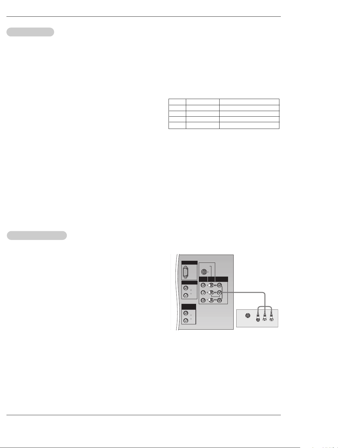
- This TV can receive Digital Over-the-air/Cable signals without an external digital set-top box. However, if you do receive Digital
signals from a digital set-top box or other digital external device, refer to the figure as shown below.
- This TV supports HDCP (High-bandwidth Digital Contents Protection) protocol for Digital Contents (480p,720p,1080i).
How to connect
Use the TV’s COMPONENT (Y, PB, PR) INPUT, RGB, HDMI1/DVI or
HDMI2 jack for video connections, depending on your set-top box connector. Then, make the corresponding audio connections.
Note: HDMI(High Definition Multimedia Interface): Input that accepts uncom-
pressed digital signal and multi channel digital audio signal.
How to use
1. Turn on the digital set-top box. (Refer to the owner’s manual for the digital
set-top box.)
2. Use TV/VIDEO on the remote control to select Component 1,
Component 2, RGB-DTV, HDMI1/DVI or HDMI2 source.
Monitor Out Setup
Monitor Out Setup
The TV has a special signal output capability which allows you to
hook up a second TV or monitor.
Signal
480i
480p
720p
1080i
Component 1/2
Yes
Yes
Yes
Yes
RGB-DTV,HDMI1/DVI,HDMI2
No
Yes
Yes
Yes
Connect the second TV or monitor to the TV’s MONITOR OUTPUT.
See the Operating Manual of the second TV or monitor for further
details regarding that device’s input settings.
Note
• Component, RGB-PC/RGB-DTV, HDMI1/DVI,HDMI2, DTV input
sources cannot be used for Monitor out.
14 DLP Projection TV
Page 16

Installation
PC Setup
PC Setup
- This TV provides Plug and Play capability, meaning that the PC adjusts automatically to the TV's settings.
- The TV perceives 640x480, 60Hz as DTV 480p based on the PC graphic card, change the screen scanning rate for the graphic
card accordingly.
<When the PC supports DVI>
How to connect
1. Connect the PC to HDMI1/DVI port of this TV with an HDMI-to-DVI cable(not supplied with this product).
If you do not need to connect audio, HDMI2 port is also available for the DVI video connection.
2. If the PC(or the sound card of the PC) has a fiber optic digital audio output connector, connect the PC's audio output to DIGI-
TALAUDIO(OPTICAL) port for DVI INPUT.
3. If the PC(or the sound card of the PC) has an analog audio output connector, connect the PC's audio output to AUDIO INPUT
port located on the right side of RGB INPUT port.
How To Use
1. To get the best picture quality, adjust the PC graphics card to 1024x768, 60Hz.
2. Select HDMI1/DVI input source in main input option of SETUP menu.(Refer to P.61)
TV/VIDEO button is also available for this purpose.
3. Check the image on your TV. There may be noise associated with the resolution, vertical pattern, contrast or brightness in PC
mode. If noise is present, change the PC output to another resolution, change the refresh rate to another rate or adjust the
brightness and contrast on the VIDEO menu until the picture is clear. If the refresh rate of the PC graphic card can not be
changed, change the PC graphic card or consult the manufacturer of the PC graphic card.
<When the PC supports RGB>
How to connect
1. Connect the PC to RGB INPUT port of this TV with a RGB cable(not supplied with this product).
2. If the PC(or the sound card of the PC) has an analog audio output connector, connect the PC's audio output to AUDIO INPUT
port located on the right side of RGB INPUT port.
How To Use
1. To get the best picture quality, adjust the PC graphics card to 1024x768, 60 Hz.
2. Select RGB-PC input source in main input option of SETUP menu.(Refer to P.61)
Once you select RGB-PC in main input option of SETUP menu, TV/VIDEO button is also available for this purpose.
3. Check the image on your TV. There may be noise associated with the resolution, vertical pattern, contrast or brightness in PC
mode. If noise is present, change the PC output to another resolution, change the refresh rate to another rate or adjust the
brightness and contrast on the VIDEO menu until the picture is clear. If the refresh rate of the PC graphic card can not be
changed, change the PC graphic card or consult the manufacturer of the PC graphic card.
Monitor Display Specifications (RGB-PC or HDMI/DVI Mode)
Resolution
640x350
640x480
800x600
1024x768
Horizontal
Frequency(KHz)
31.468
31.469
37.861
37.500
35.156
37.879
48.077
46.875
48.363
56.476
60.023
Vertical
Frequency(Hz)
70.09
59.94
72.80
75.00
56.25
60.31
72.18
75.00
60.00
70.06
75.02
Owner’s Manual 15
Page 17
Installation
PC/DTV
(XGA
/480p
/720p
/1080i)
S-VIDEO
MONO
RGB INPUT
RGB/DVI INPUT
(L)
(R)
AUDIO
(L)
(R)
AUDIO
MONITOR
OUT
INPUT2
INPUT1
VARIABLE
AUDIO OUT
Digital
Digital
Audio Output
Audio Output
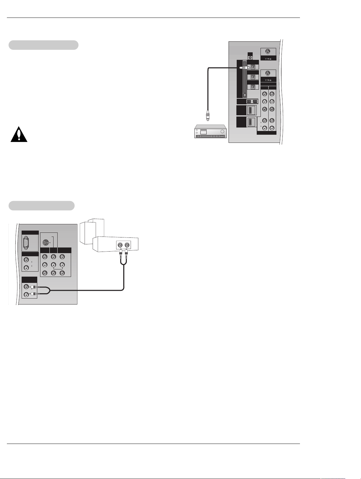
Send the TV’s audio to external audio equipment (stereo system) via
the Digital Audio Output (Optical) port.
How to connect
1. Connect one end of an optical cable to the TV Digital Audio
(Optical) Output port.
2. Connect the other end of the optical cable to the digital audio (optical) input on the audio equipment.
3. Set the “ TV Speaker option - Off” in the AUDIO menu. Refer to
page 64.
See the external audio equipment instruction manual for operation.
Caution: Do not look into the optical output port. Looking
External Stereo
External Stereo
at the laser beam may damage your vision.
Hook up Variable Audio Output, L-Audio-R to Amplifier system for
Left/Right front speaker sound.
G-LINK
ANTENNA
DIGITAL AUDIO
C
a
b
l
e
C
A
R
D
IEEE-1394
HDMI1
/DVI
HDMI2
OPTICAL OUTPUT
DIGITAL AUDIO
OPTICAL INPUT1
(COMPONENT2)
DIGITAL AUDIO
OPTICAL INPUT2
(DVI)
COMPONENT
INPUT2 INPUT1
Y
PB
PR
(L)
AUDIO
(R)
DTV/DVD INPUT
CABLE
C
A
B
L
E
C
A
R
D
DVI
HDMI
16 DLP Projection TV
How to connect
1. Locate the Variable Audio Out jacks on the back of your TV and the
Input jacks on the back of your stereo's amplifier.
2. Connect the two jacks, making sure that the right and left channels
are connected correctly.
3. Set up your speakers through your analog stereo amplifier, according to the instructions provided with the amplifier.
Page 18

Installation
HDMI
HDMI
- HDMITM, the HDMI logo and High-Definition Multimedia Interface is a trademark or registered trademark of HDMI Licensing.
- This TV can receive the High-Definition Multimedia Interface(HDMI) or the Digital Visual Interface(DVI).
- This TV supports HDCP(High-bandwidth Digital Contents Protection) Protocol for 720x480p, 1280x720p, and 1920x1080i resolution.
- When you connect this TV with a source device(DVD player, Set Top Box or PC) supporting Auto HDMI/DVI function, the output
resolution of the source device will be automatically set to 1280x720p.
- If the source device does not support Auto HDMI/DVI, you need to set the output resolution appropriately.
To get the best picture quality, adjust the DVD Player or Set Top Box's output resolution to 1280x720p, and the PC graphics card's
output resolution to 1024x768, 60Hz.
- If the source device has an HDMI output, no other audio connection is necessary because HDMI-to-HDMI connection includes
both video and audio.
- If the source device has a DVI output and no HDMI output, a separated audio connection is necessary.
<When the source device(DVD player or Set Top Box) supports HDMI>
How To Connect
1. Connect the source device to HDMI1/DVI or HDMI2 port of this TV with an HDMI cable(not supplied with this product).
2. No separated audio connection is necessary.
How To Use
- If the source device supports Auto HDMI function, the output resolution of the source device will be automatically set to 1280x720p.
- If the source device does not support Auto HDMI, you need to set the output resolution appropriately.
To get the best picture quality, adjust the output resolution of the source device to 1280x720p.
- Select HDMI1/DVI or HDMI2 input source in main input option on the SETUP menu.(Refer to P.61)
TV/VIDEO button is also available for this purpose.
<When the source device(DVD player or Set Top Box) supports DVI>
How To Connect
1. Connect the source device to HDMI1/DVI port of this TV with a HDMI-to-DVI cable(not supplied with this product).
Do not use HDMI2 port for DVI connection if you want to connect audio.
2. A separated audio connection is necessary.
3. If the source device has a fiber optic digital audio output, connect the audio output to DIGITAL AUDIO(OPTICAL) port for DVI
INPUT.
4. , connect the PC's audio output to AUDIO INPUT port located on the right side of RGB INPUT port.
How To Use
- If the source device supports Auto DVI function, the output resolution of the source device will be automatically set to 1280x720p.
- If the source device does not support Auto DVI, you need to set the output resolution appropriately.
To get the best picture quality, adjust the output resolution of the source device to 1280x720p.
- Select HDMI1/DVI input source in main input option on the SETUP menu.(Refer to P.61)
TV/VIDEO button is also available for this purpose.
Owner’s Manual 17
Page 19

Installation
Reference
Reference
Cable sample
HDMI Cable
(not supplied with the product)
HDMI to DVI Cable
(not supplied with the product)
Fiber Optic Digital Audio Cable
(not supplied with the product)
Analog Audio Cable(RCA type)
(not supplied with the product)
Analog Audio Cable(Stereo to RCA type)
(not supplied with the product)
18 DLP Projection TV
Page 20

Installation
How to use
1. Connect the HDMI1/DVI Source Devices(DVD Player or Set Top Box or PC) and the TV SET.
2. Turn on the display by pressing the POWER button on the TV SET and HDMI1/DVI Source Devices remote control.
3. Select HDMI1/DVI Input source in Main Input option on the SETUP menu.(Refer to P.61)
4. Check the image on your TV SET. There may be noise associated with the resolution, vertical pattern, contrast or brightness in
HDMI1/DVI Source Devices. If noise is present, change the HDMI1/DVI Source Devices to another resolution, change the
refresh rate or adjust the brightness and contrast on the menu until the picture is clear. If the refresh rate of the PC graphics
card can not changed, change the PC graphics card or consult the manufacturer of the PC graphics card.
Notes:
- Depending on the graphics card, DOS mode may not work if a HDMI to DVI Cable is in use.
- Avoid keeping a fixed image on the screen for a long period of time. The fixed image may become permanently imprinted on the
screen.
- When Source Devices connected with HDMI1/DVI Input, output PC Resolution(VGA, SVGA, XGA), Position and Size may not fit
to Screen. As shown the picture below, press the ADJUST button to adjust the screen Position of TV SET and contact an PC
graphics card service center.
- When Source Devices connected with HDMI1/DVI Input, output TV SET Resolution(480p, 720p, 1080i) and TV SET Display fit
EIA/CEA-861-B Specification to Screen. If not, refer to the Manual of HDMI1/DVI Source Devices or contact your service center.
- In case HDMI1/DVI Source Devices is not connected Cable or poor cable connection, "NO SIGNAL" OSD display in HDMI1/DVI
Input. In case that Video Resolution is not supported TV SET output in HDMI1/DVI Source Devices, "INVALID FORMAT" OSD
display. Refer to the Manual of HDMI1/DVI Source Devices or contact your service center.
POSITION G
Adjust
SIZE
PHASE
RESET
Close
D
F
G
E
PC mode
In This Mode, the Supported TV Set Resolution Specification
- 1920 x 1080 I @ 59.94Hz / 60Hz, 16:9
- 1280 x 720 P @ 59.94Hz / 60Hz, 16:9(preferred format)
- 720 x 480 P @ 59.94Hz / 60Hz, 16:9
- 720 x 480 P @ 59.94Hz / 60Hz, 4:3
In This Mode, the Supported PC Resolution Specification
- 640 x 350 @ 70Hz
- 640 x 480 @ 60Hz
- 640 x 480 @ 72Hz
- 640 x 480 @ 75Hz
- 800 x 600 @ 56Hz
- 800 x 600 @ 60Hz
- 800 x 600 @ 72Hz
- 800 x 600 @ 75Hz
- 1024 x 768 @ 60Hz(preferred format)
- 1024 x 768 @ 70Hz
- 1024 x 768 @ 75Hz
Owner’s Manual 19
Page 21

Operation
Operation
urning the TV On
TTurning the TV On
* In this manual, the OSD (On Screen Display) may be different from your TV’s because it is just an
example to help you with the TV operation.
Turning on the TV just after installation
1. Connect power cord correctly.
2. Press the POWER button on the TV. At this moment, the TV is switched to standby mode. Press the
TV INPUT, TV/VIDEO, CH (
ton on the TV front panel and then the TV will switch on.
), Number (0 ~ 9) button on the remote control or press the CH (
D/ E
D/ E
Operation
) but-
Turning on the TV (power cord is still connected)
1. If the TV was turned off with indicators on the TV
• Check the power cable.
2. If the TV was turned off with the remote control and the POWER button on the TV
• Press the POWER button on the TV or press the POWER, TV/VIDEO, CH (
button on the remote control to turn the TV on.
Notes:
• If you intend to be away on vacation, disconnect the power plug from the wall power outlet.
• The TV Guide On Screen and any CableCARDTMSoftware upgrades work while the TV is in standby
• mode. If you pull the power plug cord the TV Guide On Screen will not update its listings and no •••
• CableCARDTMSoftware upgrades will occur.
• After turning on the TV, it could take up to a week for the TV Guide On Screen system to receive full list-
• ings data.
), Number (0 ~ 9)
D/ E
20 DLP Projection TV Owner’s Manual 20
Page 22

Operation
TV Setup
TV Setup
On-screen Menus Language Selection
On-screen Menus Language Selection
- The menus can be shown on the screen in the selected language. First select your language.
1. Press the MENU button and then use
menu.
2. Press the G button and then use
3. Press the G button and then use
From this point on, the on-screen menus will be shown in the selected language.
4. Press EXIT button to return to TV viewing or press MENU button to return to
the previous menu.
D/ E
button to select your desired language.
D/ E
button to select the OPTION
D/ E
button to select Language.
Owner’s Manual 2121 DLP Projection TV
Page 23

Operation
Setup Menu Options
Setup Menu Options
EZ Scan (Channel Search)
EZ Scan (Channel Search)
- Automatically finds all channels available through antenna or cable inputs, and stores them in memory on the channel list.
- Run EZ Scan again after any Antenna/Cable connection changes.
- A password is required to gain access to EZ Scan menu if the Lock System is turned on.
1. Press the MENU button and then use
2. Press the G button and then use
3. Press the G button or ENTER button to begin the channel search.
Allow EZ Scan to complete the channel search cycle for TV, DTV, CATV, and CADTV.
Channel Edit
Channel Edit
- Create two different types of channel lists in memory: “Custom List” and
“Favorite List” from the default channel list created from the EZ Scan channel
search.
- A Custom List can be created by toggling each channel on or off with ENTER
button. The channels in the Custom List are displayed in black color, and the
channels deleted from the Custom List are displayed in gray color. Once a
channel is highlighted you can add or delete the channel by referring to the
small window at the top-left corner of the screen.You can create your own
Favorite List.
Use the FAV button on the remote control when a channel is highlighted and
then you can add or delete the channel to/from the Favorite List.
1. Press the MENU button and then use
2. Press the
3. Press the
a preview picture.
4. Use
add or delete it. Press FAV to add or delete the channel to the Favorite List.
5. Press EXIT button to return to TV viewing or press MENU button to return to the
previous menu.
G button and then use
G button. You will now see a screen filled with channel numbers and
/ F / G
D / E
button to select a channel and then use the ENTER button to
D / E
D / E
button to select the SETUP menu.
D / E
button to select EZ Scan.
button to select the SETUP menu.
D / E
button to select Channel Edit.
Note:
• When a cable box connects to the physical channel 2, 3, or 4 in TV Guide On Screen Setup, cable channels(CATV or
CADTV) will not be editable by Channel Edit. Instead, use the cable box's Channel Edit if available.
22 DLP Projection TV Owner’s Manual 22
Page 24
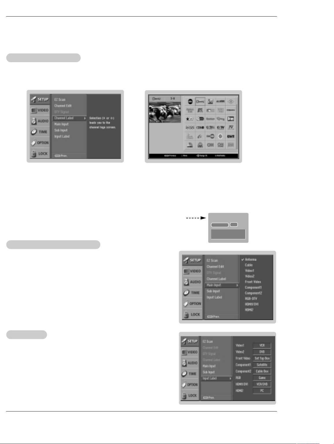
Channel Label Setup
Channel Label Setup
- Choose preset labels for your channels.
- If a channel label is provided on the signal from the broadcasting station, the TV displays a short name for a DTV channel - even if you didn't preset a label for the channel.
Operation
1. Press the MENU button and then use
2. Press the G button and then use
D / E
button to select the SETUP menu.
D / E
button to select Channel Label.
3. Press the G button. You will now see a screen filled with Labels and a preview screen.
4. Use the CH
5. Use
D / E
button to select a channel to Label.
D / E
/ F / G button to select the appropriate label for the channel, then press ENTER button to set the Label to
the selected channel.
- If you press ENTER button in TV viewing mode, you will see the channel banner.
Main Picture Source Selection
Main Picture Source Selection
- Changes the picture source so you can watch your off-air TV, cable TV, VCR,
DVD, or any other devices that are connected to your TV.
1. Press the MENU button and then use
2. Press the
3. Press the
G button and then use
G button and then use
D / E
D / E
button to select the SETUP menu.
D / E
button to select Main Input.
button to select the source: Antenna,
Cable, Video1, Video2, Front Video, Component1, Component2, RGB-DTV (or
RGB-PC), HDMI1/DVI or HDMI2.
4. Press EXIT button to return to TV viewing or press MENU button to return to the
previous menu.
Input Label
Input Label
CADTV
Dolby Digital
27-1
HD
CNN
1. Press the MENU button and then use
2. Press the G button and then use
3. Press the G button and then use
D / E
D / E
button to select the SETUP menu.
D / E
button to select Input Label.
button to select the source: Video1,
Video2, Front Video, Component1, Component2, RGB, HDMI1/DVI or HDMI2.
4. Press EXIT button to return to TV viewing or press MENU button to return to the
previous menu.
23 DLP Projection TV Owner’s Manual 23
Page 25
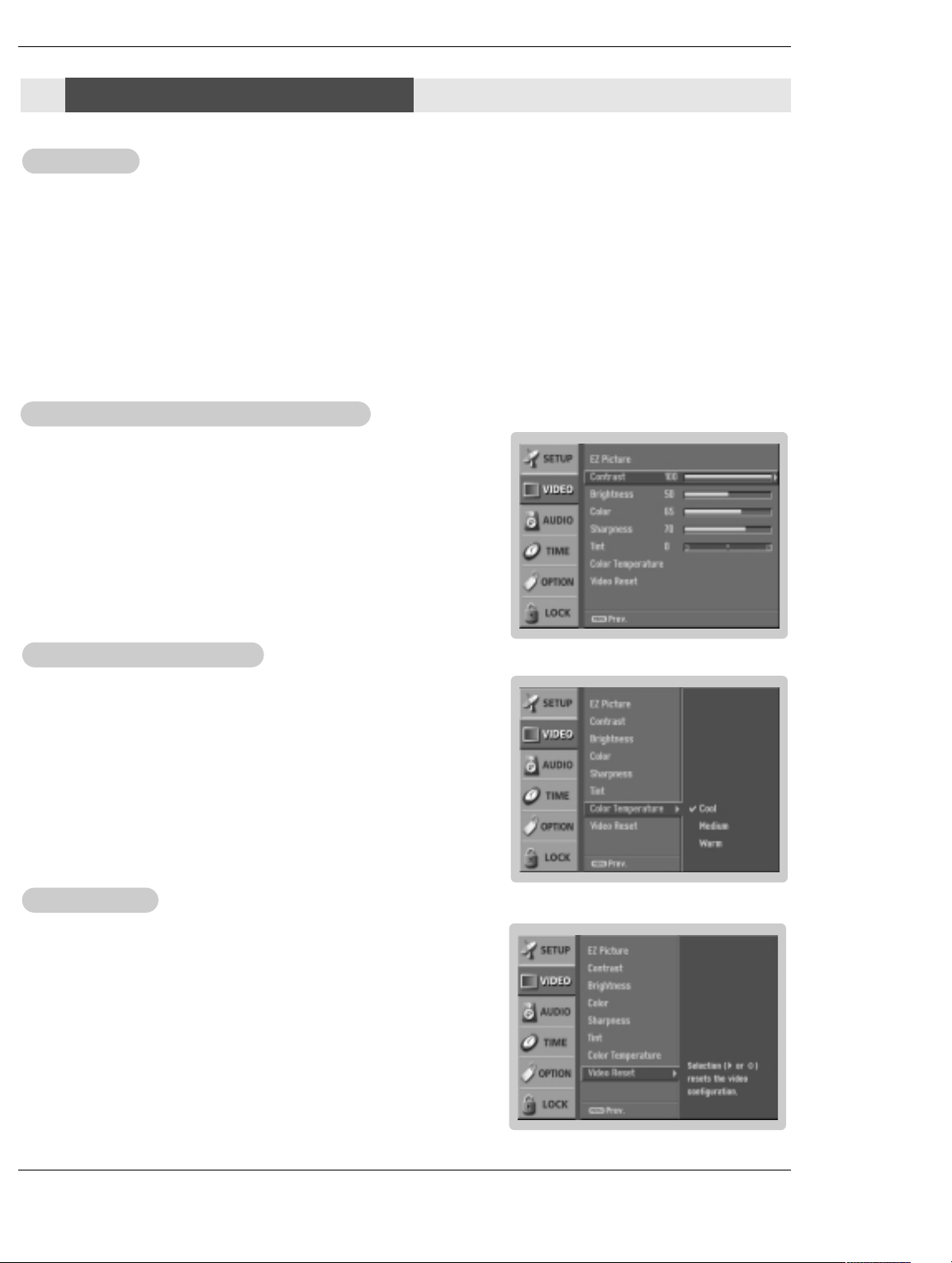
Operation
ideo Menu Options
VVideo Menu Options
EZ Picture
EZ Picture
- EZ Picture adjusts the TV for the best picture appearance. Select the preset value in the EZ Picture menu based on the
program category.
- When adjusting Video menu options (contrast, brightness, color, sharpness, tint, and color temperature) manually, EZ
Picture automatically changes to Custom.
- Daylight, Normal, Night Time, Movie, Video Game, and Sports settings are preset for optimum picture quality at
the factory and are not adjustable.
1. Press the EZ PIC button repeatedly to select the picture appearance setup option as shown below:
Custom (your own settings), Daylight, Normal, Night Time, Movie, Video Game, and Sports.
• You can also use the VIDEO menu to adjust EZ Picture.
2. Press the EXIT button to save and return to TV viewing.
Manual Picture Control
Manual Picture Control
- Adjust the picture appearance to suit your preference and viewing situations.
1. Press the MENU button and then use
2. Press the G button and then use
(
Contrast, Brightness, Color, Sharpness, or Tint).
3. Press the G button and then use F / G button to make appropriate adjustments.
4. Press EXIT button to return to TV viewing or press MENU button to return to the
previous menu.
Color TT
Color
- Choose one of three automatic color adjustments. Set to warm to enhance hotter
colors such as red, or set to cool to see less intense colors with more blue.
1. Press the MENU button and then use
2. Press the G button and then use
3. Press the
or
4. Press EXIT button to return to TV viewing or press MENU button to return to the
previous menu.
emperature Control
emperature Control
G button and then use
Warm.
(Custom
(
D / E
D / E
D / E
option)
option)
button to select the VIDEO menu.
D / E
button to select the desired picture option
button to select the VIDEO menu.
D / E
button to select Color Temperature .
button to select either Cool, Medium,
ideo Reset
VVideo Reset
- Use to quickly reset all the Video menu options to their original factory preset
values.
1. Press the MENU button and then use
2. Press the
3. Press the G button to reset the Video menu options to original values.
G button and then use
D / E
button to select the VIDEO menu.
D / E
button to select Video Reset .
Owner’s Manual 2424 DLP Projection TV
Page 26
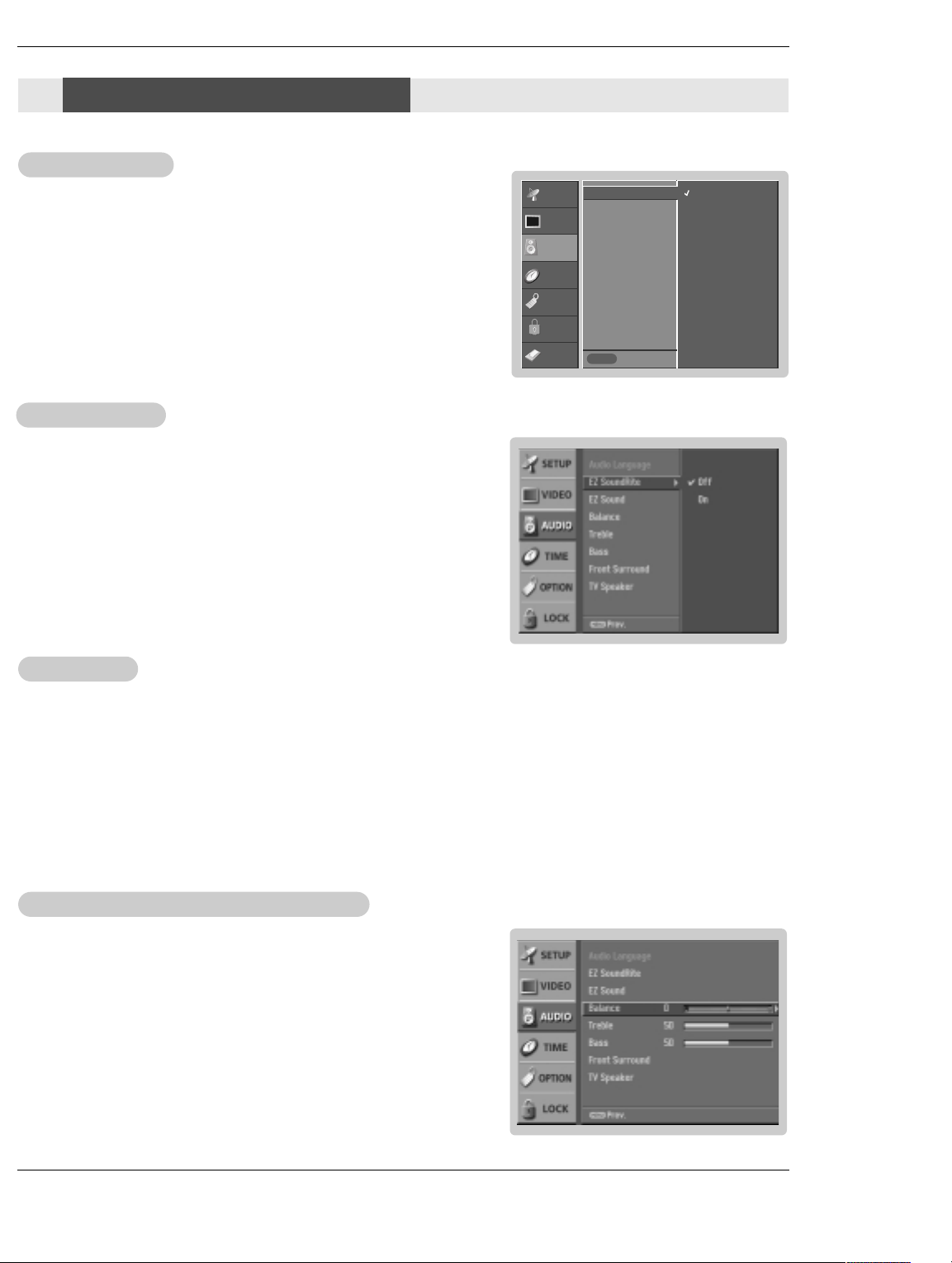
Audio Menu Options
Audio Menu Options
Audio Language
Audio Language
- Other languages may be available if a digital signal is provided by the broadcasting station.
1. Press the MENU button and then use
2. Press the G button and then use
3. Press the G button and then use
D / E
D / E
button to select the AUDIO menu.
D / E
button to select Audio Language.
button to select: English, Spanish, or
French.
4. Press EXIT button to return to TV viewing or press MENU button to return to the
previous menu.
EZ SoundRite
EZ SoundRite
- Scans for changes in sound level during commercials, then adjusts the sound
to match the specified audio level. SoundRite makes sure that the volume level
remains consistent whether you are watching a commercial or a regular TV
program.
Press the MENU button and then use
1.
2. Press the G button and then use
3. Press the
G button and then use
D / E
D / E
button to select the AUDIO menu.
D / E
button to select EZ SoundRite.
button to select On or Off.
4. Press EXIT button to return to TV viewing or press MENU button to return to the
previous menu.
SETUP
VIDEO
AUDIO
TIME
OPTION
LOCK
CABLE
Audio Language G
EZ SoundRite
EZ Sound
Balance
Treble
Bass
Front Surround
TV Speaker
Previous
MENU
Operation
English
Spanish
French
EZ Sound
EZ Sound
- EZ Sound lets you enjoy the best sound without any special adjustment because the TV sets the appropriate sound
options based on the program content.
- When adjusting sound options (treble, bass, and front surround) manually, EZ Sound automatically switches Custom.
- Normal, Stadium, News, Music and Theater are preset for good sound quality at the factory and are not
adjustable.
1. Press the EZ SOUND button repeatedly to select the appropriate sound setup as shown below:
Custom (your own settings), Normal, Stadium, News, Music and Theater.
• You can also adjust EZ Sound in the AUDIO menu.
2. Press EXIT button to save and return to TV viewing.
Manual Sound Control (Custom
Manual Sound Control (
option)
option)
- Adjust the sound to suit your taste and room situations.
Press the MENU button and then use
1.
2. Press the
G button and then use
D / E
button to select the AUDIO menu.
D / E
button to select the desired sound option
(Balance, Treble, or Bass).
3. Press the
G button and then use F / G button to make appropriate adjustments.
4. Press EXIT button to return to TV viewing or press MENU button to return to the
previous menu.
25 DLP Projection TV Owner’s Manual 25
Page 27
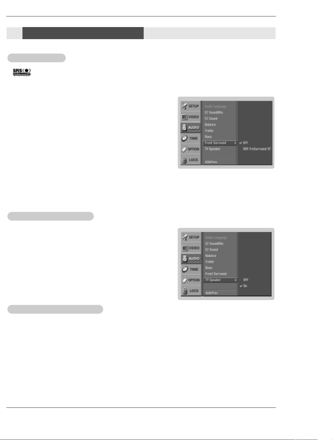
Operation
Audio Menu Options
Audio Menu Options
Front Surround
Front Surround
- is a trademark of SRS Labs, Inc.
- TruSurround XT technology is incorporated under license from SRS Labs, Inc.
- Manufactured under license from Dolby Laboratories. “Dolby” and the double-D symbol are trademarks of Dolby Laboratories.
1. Press the MENU button and then use
2. Press the
3. Press the G button and then use
System
• 3D EchoSound System
Creates a stunning simulated stereo effects from any mono sound and a realistic three-dimensional sound with a very wide and deep sound stage into
stereo sound
• SRS TruSurround XT
Takes advantage of any multi-channel format without needing to add extra
speakers or equipment. Dialog clarity, bass enrichment, and the addition of
stereo audio enhancement that produces an immersive sound experience from
standard stereo material.
4. Press EXIT button to return to TV viewing or press MENU button to return to
the previous menu.
TV Speaker On/Of
TV Speaker On/Of
- Turn TV speaker off if using external audio equipment. Feature turns the TV
Speaker option On or Off.
G button and then use
or SRS (Sound Retrieval System) TruSurround XT.
f Setup
f Setup
D / E
D / E
1. Press the MENU button and then use
2. Press the G button and then use
3. Press the G button and then use
4. Press EXIT button to return to TV viewing or press MENU button to return to the
previous menu.
D / E
D / E
button to select the AUDIO menu.
D / E
button to select Front Surround.
button to select Off, 3D EchoSound
button to select the AUDIO menu.
D / E
button to select TV Speaker.
button to select On or Off .
Stereo/SAP
Stereo/SAP
- This TV can receive MTS stereo programs and any SAP (Secondary Audio Program) that accompanies the stereo program; if
the station transmits an additional sound signal as well as the original one.
- When having selected Stereo or SAP button on the remote control, this TV can only receive the signal when the TV station
transmits the proper signals.
- Mono sound is automatically received if the broadcast is only in Mono; even though Stereo or SAP has been selected.
- Select Mono if you want to listen to the mono sound in remote fringe areas during stereo/SAP broadcasting.
- Stereo or SAP can be received in Analog channel.
1. Use the SAP button to select your desired MTS mode in analog signal. Each time you press the SAP button,
Stereo, or SAP appear in turn.
• If other languages available on the digital signal, select them with the SAP button.
2. Press EXIT button to save and return to TV viewing.
Broadcasts Setup
Broadcasts Setup
Mono,
Owner’s Manual 2626 DLP Projection TV
Page 28
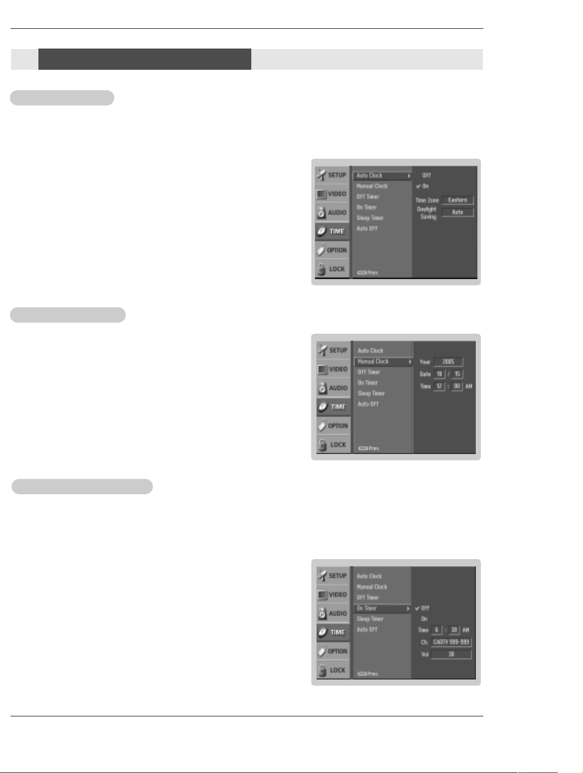
ime Menu Options
TTime Menu Options
Auto Clock Setup
Auto Clock Setup
- The time is set automatically from a digital channel signal.
- The digital channel signal includes information for the current time provided by the broadcasting station.
- Set the clock manually, if the current time is set incorrectly by the auto clock function.
- When you set up TV Guide, Auto Clock menu is not selected.
1. Press the MENU button and then use
2. Press the G button and then use
3. Press the
G button and then use
4. Press the G button and then use
Eastern, Central, Mountain, Pacific, Alaska, or Hawaii.
zone:
5. Press the G button and then use
D / E
D / E
D / E
D / E
button to select the TIME menu.
D / E
button to select Auto Clock.
button to select On.
button to select your viewing area time
button to set Daylight Saving Auto, Off
or On, depending on whether or not your viewing area observes Daylight
Savings Time.
6. Press EXIT button to return to TV viewing or press MENU button to return to
the previous menu.
Operation
Manual Clock Setup
Manual Clock Setup
- If current time setting is wrong, reset the clock manually.
- When you set up TV Guide, Manual Clock menu is not set.
1. Press the MENU button and then use
2. Press the G button and then use
3. Press the
G button and then use F / G button to select either the year, date, or
D / E
time option. Once selected, use the
D / E
button to select the TIME menu.
D / E
button to select Manual Clock.
button to set the year, date, and time
options.
4. Press EXIT button to return to TV viewing or press MENU button to return to
the previous menu.
On/Off f TT
On/Of
imer Setup
imer Setup
- Timer function operates only if current time has been set.
- Off-Timer function overrides On-Timer function if they are both set to the same time.
- The TV must be in standby mode for the On-Timer to work.
- If you do not press any button within 2 hours after the TV turns on with the On Timer function, the TV will automatically revert to
standby mode.
1. Press the MENU button and then use
2. Press the
3. Press the G button and then use
• To cancel
4. Press the Gbutton and then use
5. Press the G button and then use
6. For only
Press the G button and then use
Press the
G button and then use
On/Off timer function, select Off.
On timer function
G button and then use
D / E
D / E
D / E
D / E
D / E
D / E
button to select the TIME menu.
D / E
button to select Off Timer or On Timer.
button to select On.
button to set the hour.
button to set the minutes.
button to select the channel at turn-on.
button to set the sound level at turn-on.
7. Press EXIT button to return to TV viewing or press MENU button to return to the
previous menu.
27 DLP Projection TV Owner’s Manual 27
Page 29
Operation
ime Menu Options
TTime Menu Options
Sleep TT
Sleep
- The Sleep Timer turns the TV off at the preset time. Note that this setting is cleared when the TV is turned off.
- You can also set up the Sleep Timer in the TIME menu.
1. Press the TIMER button repeatedly to select the number of minutes. First the
followed by the following sleep timer options: 10, 20, 30, 60, 90, 120, 180, and 240 minutes.
2. When the number of minutes you want is displayed on the screen, press the ENTER button. The timer begins to
count down from the number of minutes selected.
3. To check the remaining minutes before the TV turns off, press the TIMER button once.
4. To cancel the Sleep Timer, press the TIMER button repeatedly to select
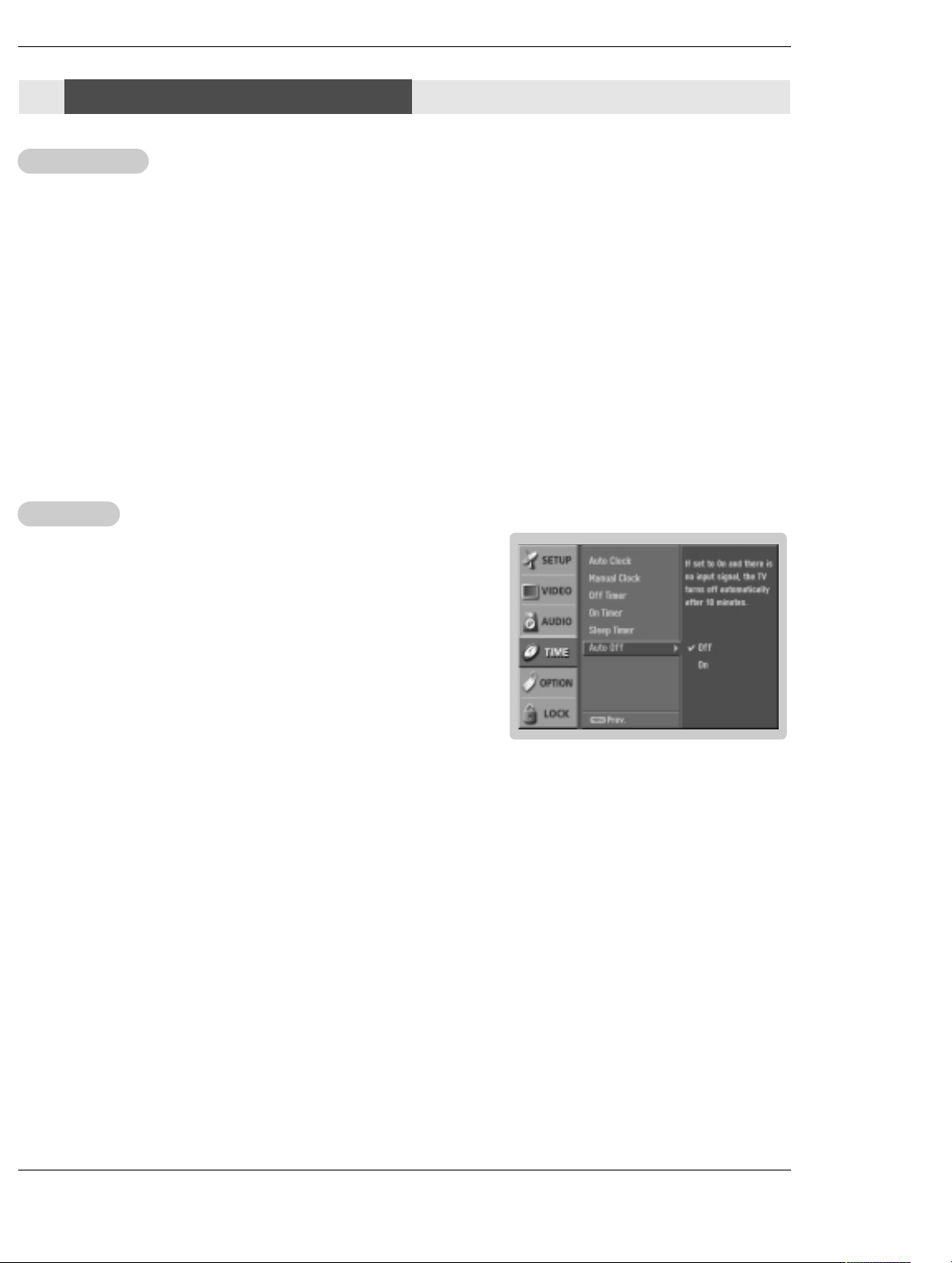
Auto Offf
Auto Of
- If set to on and there is no input signal, the TV turns off automatically after 10
minutes.
1. Press the MENU button and then use
2. Press the
3. Press the G button and then use
4. Press EXIT button to return to TV viewing or press MENU button to return to the
previous menu.
imer
imer
G button and then use
button to select the TIME menu.
D / E
button to select Auto Off.
D / E
button to select On or Off.
D / E
Off option appears on the screen,
Off.
Owner’s Manual 2828 DLP Projection TV
Page 30

Operation
Option Menu Options
Option Menu Options
Aspect Ratio Control
Aspect Ratio Control
- Lets you choose the way an analog picture with a 4:3 aspect ratio is displayed on your TV with a 16:9 ratio picture format.
When you receive an analog picture with a 4:3 aspect ratio on your 16:9 TV, you need to specify how the picture is to be displayed.
- If you are viewing a picture with a 16:9 aspect ratio, you can’t use the Horizon aspect ratio option.
- Horizon aspect ratio is not available for Component 1-2 (720p/1080i)/RGB-DTV (720p/1080i)//HDMI1/DVI-DTV
(720p/1080i)/DTV(720p/1080i), HDMI2-DTV(720p/1080i) input source.
- RGB-PC/DVI-PC input source use 4:3 or 16:9 aspect ratio.
1. Press the RATIO button repeatedly to select the desired picture format.
You can also adjust the Aspect Ratio in the OPTION menu.
Set By Program
•
Selects the proper picture proportion to match the source’s image. (4:3 → 4:3, 16:9 → 16:9)
• 4:3
Choose 4:3 when you want to view a picture with an original 4:3 aspect ratio, with black bars appearing at both
the left and right sides.
• 16:9
Choose 16:9 when you want to adjust the picture horizontally, in a linear proportion to fill the entire screen.
• Horizon
Choose Horizon when you want to adjust the picture in a non-linear proportion, that is, more enlarged at both
sides, to create a spectacular view.
• Zoom 1
Choose Zoom 1 when you want to view the picture without any alteration. However, the top and bottom portions
of the picture will be cropped.
• Zoom 2
Choose Zoom 2 when you want the picture to be altered, both horizontally extended and vertically cropped. The
picture taking a halfway trade off between alteration and screen coverage.
• Cinema Zoom
Choose Cinema Zoom when you want to enlarge the picture in correct proportion. Note: When enlarging or
reducing the picture, the image may become distorted.
You can adjust the enlarge proportion of Cinema Zoom using
button. The adjustment range is 1~16.
D / E
Cinema 3:2 Mode Setup
Cinema 3:2 Mode Setup
- Most movies are 24 frames/sec, but TV signal is 30 frames/sec.
This option lets the TV do 3:2 pull-down operation for you to watch
movies at the best motion appearance.
1. Press the MENU button and then use
2. Press the
3. Press the G button and then use
4. Press EXIT button to return to TV viewing or press MENU button to return to the
previous menu.
Note: This feature operates only in 480i mode.
29 DLP Projection TV Owner’s Manual 29
G button and then use
D / E
D / E
button to select the OPTION menu.
D / E
button to select Cinema 3:2 Mode.
button to select On or Off.
Page 31
Operation
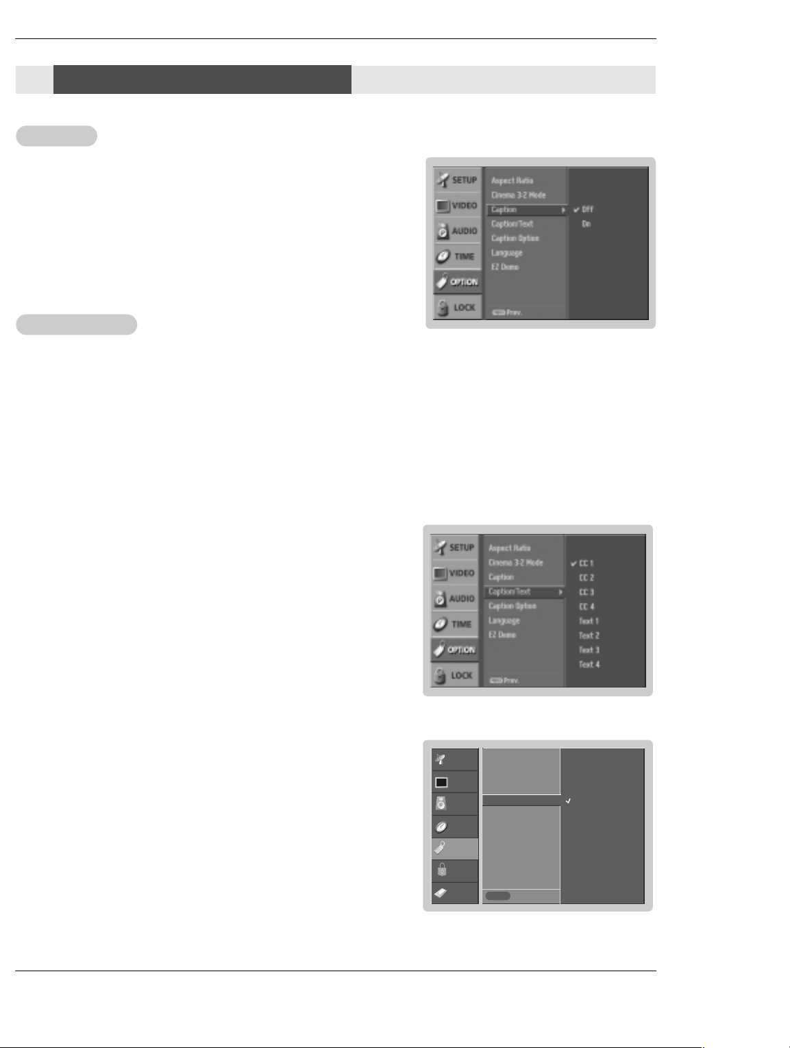
Caption
Caption
Option Menu Options
Option Menu Options
1. Press the MENU button and then use
2. Press the
3. Press the
G button and then use
G button and then use
D / E
D / E
button to select the OPTION menu.
D / E
button to select Caption.
button to select On or Off.
4. Press EXIT button to return to TV viewing or press MENU button to return to the
previous menu.
Caption/T
Caption/T
ext
ext
Analog Broadcasting System Captions
- Select a caption mode for displaying captioning information if provided on a program.
- Analog caption displays information at any position on the screen usually the program's dialog.
- Text displays information, usually at the bottom position and is used for a data service, generally not program related.
- Caption/Text, if provided by the broadcaster, would be available for both digital and analog channels on the Antenna/Cable.
- This TV is programmed to remember the caption/text mode it was last set to, when you turn the power off.
1. Use the CC button repeatedly to select Caption CC1, CC2, CC3, CC4, Text1, Text2, Text3, or Text4.
• EZ Mute shows the selected captions option (if available on program) when the TV sound is muted
2. Press EXIT button to save and return to TV viewing.
• You can also use the OPTION menu to select Caption/Text.
1. Press the MENU button and then use
2. Press the
3. Press the G button and then use
CC4, Text1, Text2, Text3, or Text4.
G button and then use
D / E
D / E
• CAPTION
The term for the words that scroll across the bottom of the TV screen; usually
the audio portion of the program provided for the hearing impaired.
• TEXT
The term for the words that appear in a large black frame and almost cover
the entire screen; usually messages provided by the broadcaster.
button to select the OPTION menu.
D / E
button to select Caption/Text.
button to select caption: CC1, CC2, CC3,
4. Press EXIT button to return to TV viewing or press MENU button to return to the
previous menu.
Digital Broadcasting System Captions
- Choose the language you want the DTV/CADTV Captions to appear in.
- Languages can be chosen for digital sources only if they are included on the
program.
1. Press the MENU button and then use
2. Press the
3. Press the
G button and then use
G button and then use
D / E
D / E
guages: English, Spanish, or French.
4. Press EXIT button to return to TV viewing or press MENU button to return to the
previous menu.
button to select the OPTION menu.
D / E
button to select Caption/Text.
button to select available caption lan-
SETUP
VIDEO
AUDIO
TIME
OPTION
LOCK
CABLE
Aspect Ratio
Cinema 3:2 Mode
Caption
Caption / Text G
Caption Option
Language
EZ Demo
MENU
Previous
English
Spanish
French
Owner’s Manual 3030 DLP Projection TV
Page 32
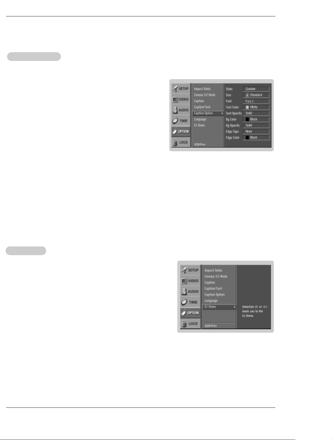
Caption Option
Caption Option
- Customize the DTV/CADTV captions that appear on your screen.
Operation
1. Press the MENU button and then use
button to select the OPTION
D / E
menu.
2. Press the G button and then use
button to select Caption Option.
D / E
3. Press the G button and then use F / G button to select Custom.
4. Use
button to customize the Style, Font, etc., to your preference. A pre-
D / E
view icon is provided at the bottom of the screen, use it to see the caption language.
• Size: Set the size the words will appear in.
• Font: Select a typeface for the words.
• Text Color: Choose a color for the text.
• Text Opacity: Specify the opacity for the text color.
• Bg (Background) Color: Select a background color.
• Bg (Background) Opacity: Select the opacity for the background color.
• Edge Type: Select an edge type.
• Edge Color: Select a color for the edges.
5. Press EXIT button to return to TV viewing or press MENU button to return
to the previous menu.
EZ Demo
EZ Demo
Shows you how to navigate the TV's on-screen menus.
EZ Demo Use to scan the features and menu options available on your TV.
1. Press the MENU button and then use
button to select the OPTION
D / E
menu.
2. Press the G button and then use
button to select EZ Demo, then use the G
D / E
button to start EZ Demo.
3. Press EXIT button to stop EZ Demo.
.
31 DLP Projection TV Owner’s Manual 31
Page 33

Operation
Lock Menu Options
Lock Menu Options
Parental Control can be used to block specific channels, ratings and other viewing sources.
The Parental Control Function (V-Chip) is used to block program viewing based on the ratings sent by the broadcasting station.
The default setting is to allow all programs to be viewed. Viewing can be blocked by the type of program and by the categories
chosen to be blocked. It is also possible to block all program viewing for a time period. To use this function, the following must be
done :
1. Set ratings and categories to be blocked.
2. Specify a password
3. Enable the lock
V-Chip rating and categories
Rating guidelines are provided by broadcasting stations. Most television programs and television movies can be blocked by TV
Rating and/or Individual Categories. Movies that have been shown at the theaters or direct-to-video movies use the Movie Rating
System (MPAA) only.
Ratings for Movies previously shown in theaters:
Movie Ratings :
• Blocking Off (Permits all programs)
• G (General audience)
• PG (Parental guidance suggested)
• PG-13 (Parents strongly cautioned)
• R (Restricted)
• NC-17 (No one 17 and under admitted)
• X (Adult only)
If you set PG-13 : G and PG movies will be available , PG-13, R, NC-17 and X will be blocked.
Ratings for Television programs including made-for-TV movies :
• TV-G (General audience)
• TV-PG (Parental guidance suggested)
• TV-14 (Parents strongly cautioned)
• TV-MA (Mature audience only)
• TV-Y (All children)
• TV-Y7 (Children 7 years older)
TV Rating Children:
• Age (applies to TV-Y, TV-Y7)
• Fantasy Violence (applies to TV-Y7)
TV Rating General:
• Age (applies to TV-G, TV-PG, TV-14, TV-MA)
• Dialogue - sexual dialogue (applies to TV-PG, TV-14)
• Language - adult language (applies to TV-PG, TV-14, TV-MA)
• Sex - sexual situations (applies to TV-PG, TV-14, TV-MA)
• Violence (applies to TV-PG, TV-14, TV-MA)
Input Block
• Video 1, 2, Front Video (On, Off)
• Component 1, 2 (On, Off)
• RGB, HDMI1/DVI or HDMI2 (On, Off)
Owner’s Manual 3232 DLP Projection TV
Page 34
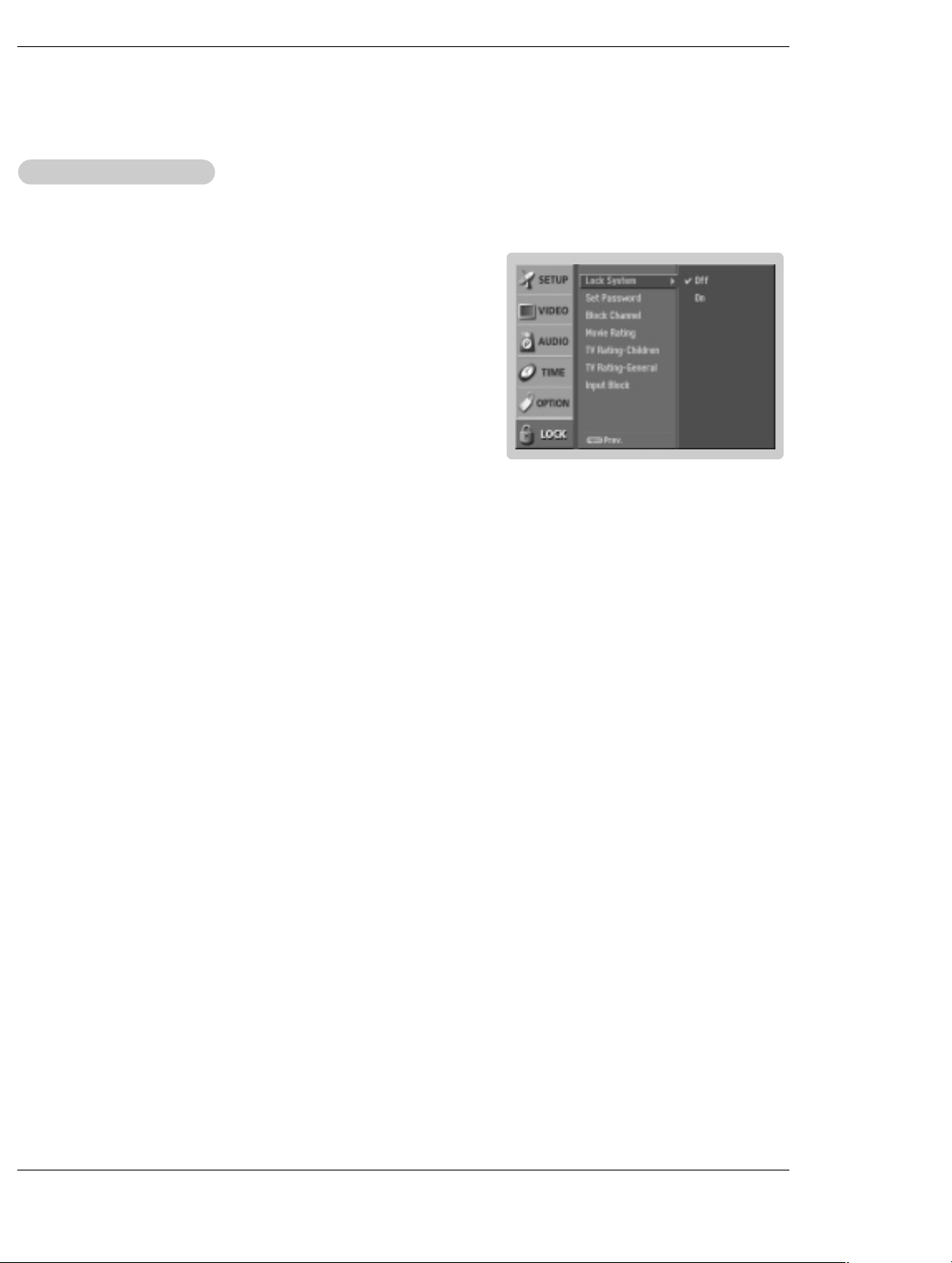
Parental Lock Setup
Parental Lock Setup
- Set up blocking schemes to block specific channels, ratings, and external viewing sources.
- A password is required to gain access to this menu.
Operation
1. Press the MENU button and then use
Then, press the G button
• Enter the password as requested.
• The TV is set up with the initial password “0-0-0-0”.
2. Use the
option is selected, change the settings to your preference.
• Lock System: Activates or disables the blocking scheme you set up previ-
ously.
• Set Password: Change the password by inputting a new password twice.
• Block Channel: Blocks any channels that you do not want to watch or
that you do not want your children to watch.
• Movie Rating (MPAA): Blocks movies according to the movie ratings lim-
its specified, so children cannot view certain movies. You can set the ratings limit by blocking out all the movies with the ratings above a specified
level. Keep in mind that the movie ratings limit only applies to movies
shown on TV, not TV programs, such as soap operas.
• TV Rating-Children: Prevents children from watching certain children's TV
programs, according to the ratings limit set. The children rating does not
apply to other TV programs. Unless you block certain TV programs intended for mature audiences in the TV Rating - sub menu, your children can
view those programs.
• TV Rating-General: Based on the ratings, blocks certain TV programs that
you and your family do not want to view.
• Input Block: Enables you to select a source to block from the external
source devices you have hooked up.
3. Press EXIT button to return to TV viewing or press MENU button to return to
the previous menu.
button to choose from the following Lock Menu options. Once the
D / E
button to select the LOCK menu.
D / E
Note : If you ever forget your password, key in ‘7’, ‘7’, ‘7’, ‘7’ on the remote con
trol.
33 DLP Projection TV Owner’s Manual 33
Page 35
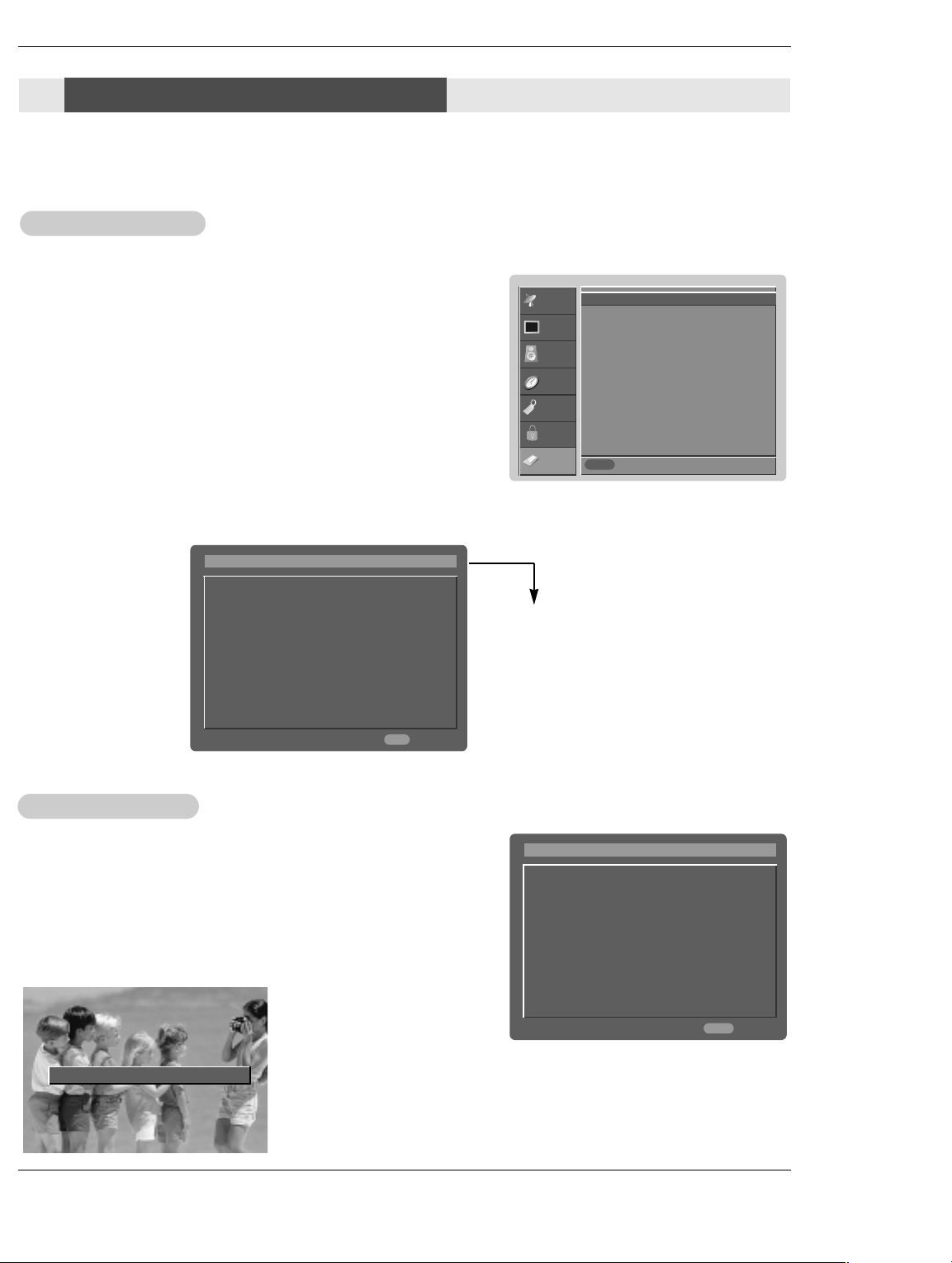
Operation
CableCARD™™
CableCARD
Function
Function
* In this manual, the OSD (On Screen Dispaly) may be different from your TV’s because it is just example to help
the TV operation.
Cable menu options
Cable menu options
- The Cable sub menu displays when inserting the CableCARDTMto the TV.
In case of Scientific Atlanta CableCARD™
- The CableCARDTMtype is Motorola, Scientific Atlanta (SA), or SCM etc. The
OSD (On screen display) is different from your TV according to your
CableCARDTMtype.
1. Press the MENU button and then use
button to select the CABLE
D / E
menu.
2. Press the G button and then use
3. Press the
G button.
button to select your desired item.
D / E
4. Press EXIT button to return to TV viewing.
SETUP
VIDEO
AUDIO
OPTION
LOCK
CABLE
SA CableCARD Diag Screen G
SA CableCARD/Host ID Screen
TIME
Previous
MENU
i.e) CableCARD™/ Host ID Screen
CableCARD (tm) Message
In order to start service for
this device, please contact
customer service at
Ph#: 1-866-303-0422
CableCARD (tm): 0-010-405-698-001
HOST ID: 0-080-000-000-226
As shown, the pairing number means your TV and
CableCARDTMID. For further information regarding
cable TV service, contact
your local cable TV service
provider(s).
Exit
EXIT
Scrambled channel
Scrambled channel
- Insert the CableCARDTM. If you do it at first, it takes about 1 minute to
exchange the data between the TV and the CableCARDTM. Then, TV screen
displays as shown right.
- Let your cable TV service provider know the CableCARDTMID and Host ID.
- If your cable TV service provider has registered the CableCARDTMID and Host
ID, you can watch the premium or high value channel.
- If you ever registered to the cable TV service provider, you can watch the pre-
mium or high value channel without a message.
Please call your operator and report an invalid CableCARDTM.
- If the certificate doesn’t match between the TV and the cableCARD
the OSD (On screen display) displays as shown left.
CableCARD (tm) Message
In order to start cable service for this device,
please contact SuperVision Cable at
1-800-555-8888
POD ID: 7-561-034-449-009
Host ID: 0-100-331-784-018
TM
Owner’s Manual 3434 DLP Projection TV
Exit
EXIT
,
Page 36
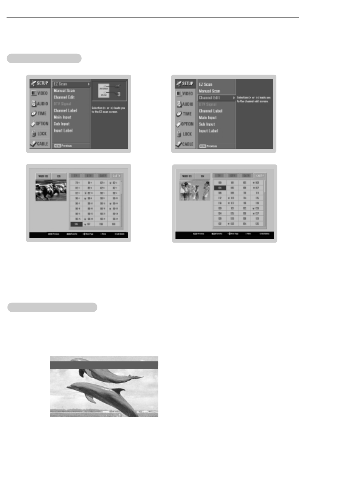
Cable Channel List
Cable Channel List
1. 2.
Operation
3.
1. If you enter the Channel Edit after running the EZ Scan without CableCARDTM, you can see the cable channel list as the
picture 3 above.
2. Insert the CableCARD
2~3 minutes to gather the cable channel list after inserting the CableCARDTMas the picture 4 above. (Occasionally more
than that time)
Note:
• As data gathering is done by the CableCARDTM, you may hear a fan run in standby mode.
Emergency
Emergency
- If an emergency situation occurs while watching the TV/DTV/CATV/CADTV, you can see a message from cable
TV service provider(s).
- When receiving an emergency message, the message is displayed on the screen as shown below or the channel
is changed automatically to a channel that maintains the emergency message. The message will automatically disappear.
TM
. Then, the TV will receive a new cable channel list which is usually one part channel. It takes about
Alert Message
Alert Message
4.
Emergency Action Notification
35 DLP Projection TV Owner’s Manual 35
Hurricane will be coming!!!
Page 37
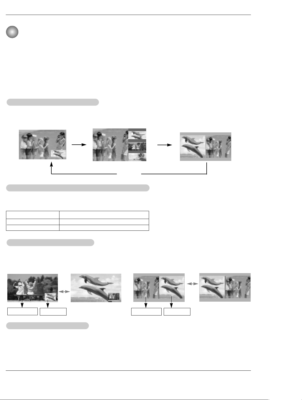
Operation
Remote Control
Remote Control
PIP (Picture-In-Picture) / Twin Picture
- PIP lets you view 2 different inputs (sources) on your TV screen at the same time. One source will be large, and the other
source will show a smaller inset image.
- Twin Picture mode splits the screen into 2, allowing 2 picture sources to be shown on the TV screen at the same time. Each
source is given half the screen.
- If you set the block/rating for Lock menu options in PIP/Twin Picture mode, “Rating Blocked” doesn’t display on screen.
atching PIP/T
WWatching PIP/T
Press the PIP button to access the sub picture. Each press of PIP changes the PIP options as shown below.
PIP Mode POP Mode
Selecting an Input Signal Source for PIP/T
Selecting an Input Signal Source for PIP/T
Use the PIP INPUT button to select the input source for the sub picture. Each press of PIP INPUT button changes
the PIP source. You can also select sources for the Sub Input in the SETUP menu.
Main Picture Source
DTV
Analog
Swapping the PIP/T/T
Swapping the PIP
Repeatedly, use the SWAP button to switch the main and sub pictures.
• Component 1, Component 2, RGB-PC (or RGB-DTV), HDMI/DVI input sources for the main picture can’t be used to
swap the main and sub pictures.
win Picture
win Picture
Available Sub Picture Sources
Analog, Video, and Front Video
DTV, Analog, Video, and Front Video
win Picture
win Picture
D
F TV 2-0
E
TV 4-0
TV 6-0
PIP Off
win Picture
win Picture
Twin Picture Mode
Main Picture
TV Program selection for PIP
TV Program selection for PIP
1. Press the PIP button.
2. Select the Antenna or Cable option on the Sub input menu or with the PIP INPUT button. Use the PIPCH+
PIPCH- button to select a channel for the sub picture.
(You can’t select DTV for main and sub picture simultaneously).
36 DLP Projection TV Owner’s Manual 36
Sub Picture Main Picture
Sub Picture
/
Page 38
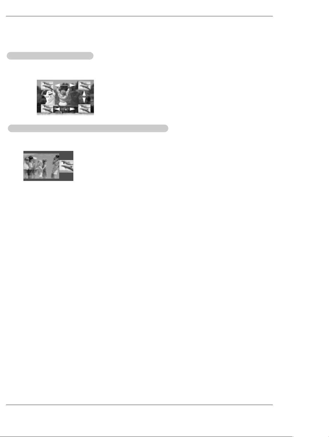
Operation
Moving the PIP
Moving the PIP
In PIP mode, press the
screen.
Adjusting Main and Sub Picture Sizes for TT
Adjusting Main and Sub Picture Sizes for
Use the
i.e)
/ F / G button to change main and sub picture sizes in Twin Picture mode.
D / E
sub picture
sub picture
/ F / G
D / E
If screen is adjusted to the
maximal size, the large
screen appears the black
part at both the up and
down sides.
button to move the sub picture to a different location on the
win Picture
win Picture
Owner’s Manual 3737 DLP Projection TV
Page 39
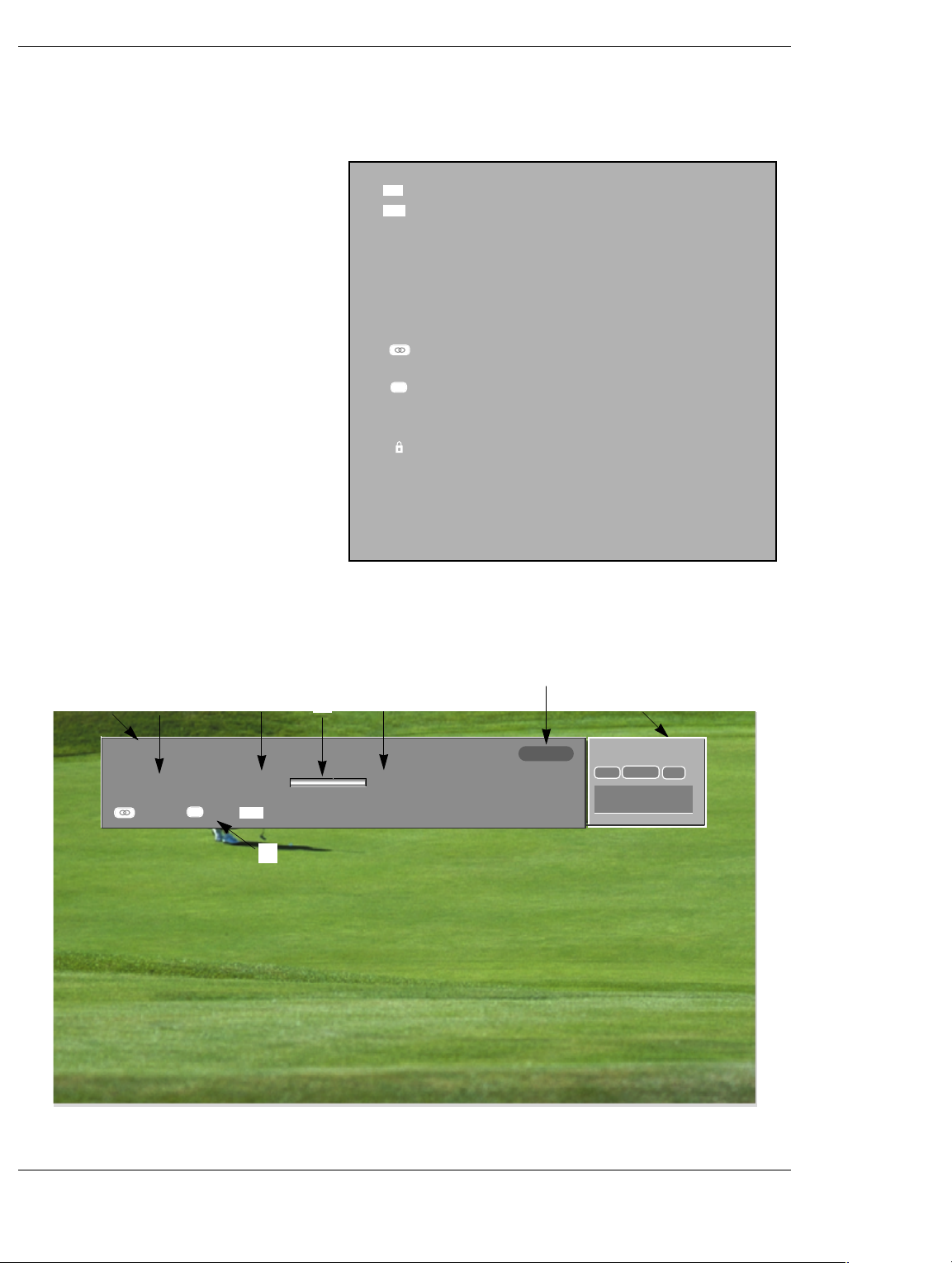
Operation
Brief Info.
Operation: • Watching TV/DTV/CATV/CADTV
• Watching Video1, Video2, Video3
• Watching IEEE 1394
• In Component1, Component2, RGB,
HDMI/DVI modes, INFO button is not
working.
Function: • Show the present screen information.
• On Watching with the upper Input signal,
press the INFO button.
• Press the INFO button or EXIT button to
exit.
A: Banner information
B: Program title
C: Day, Month, Year
D: Program start time
E: Program finish time
F: Show the prosessing rate
G: Present time
H: Added information. Refer to the icon
explanation.
4 : 3
Screen Ratio of Input Signal 4:3
16 : 9
Screen Ratio of Input Signal 16:9
480i
Resolution of Input Signal 720x480i
480p
Resolution of Input Signal 720x480p
720p
Resolution of Input Signal 1280x720p
1080i
Resolution of Input Signal 1920x1080i
Multilingual : Input Signal have over two Audio information. Press the SAP button to select wanted Audio.
CC
Caption: Input Signal have over one Close service.
Press the CC button to select wanted Closed caption.
Input Signal has rating information . Refer to the
<Lock Menu>.
D (Dialogue), L (Language), S (Sex), V (Violence), FV
(Fantasy Violence)
B
C
Live Eden 1080I
Sat, Dec 20, 2003
Multilingual
CC
Caption
D
7:00PM
Wide
16 : 9
H
G
TV 6-0
MONO
A
STEREO
CNBC
SAP
F
E
3:11AM
9:00PM
Owner’s Manual 3838 DLP Projection TV
Page 40
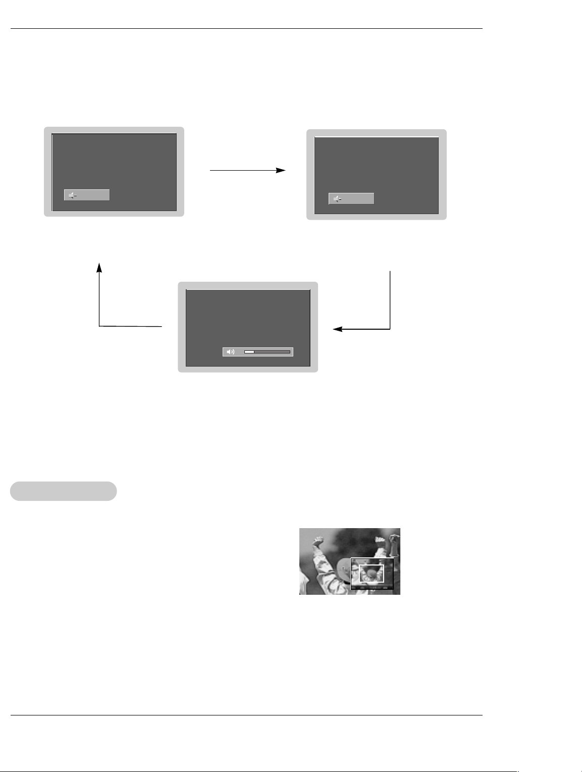
EZ Mute
- If you set the Caption on, nothing to do with the MUTE button, Caption function operates as Caption on or off.
- When you repeatedly press the MUTE button, the screen is displayed in turn. (Refer to the lower picture)
Operation
Mute
Mute : Sound is muted.
Mute Off : Sound is enabled.
Note: EZ Mute only operates in DTV/Analog/Video/Front Video.
EZ Mute
EZ Mute : a special mute mode to
activate the closed caption,
automatically.
24
Freeze & Magnify
- Enlarges the picture with correct proportions.
- When enlarging the picture, the image may become distorted.
1. Press the FREEZE button in DTV 720p, or 1080i modes.
2. Use the
3. To return to normal viewing, press the FREEZE button again.
39 DLP Projection TV Owner’s Manual 39
/ F / G buttons to select the screen split zoom section.
D / E
Page 41
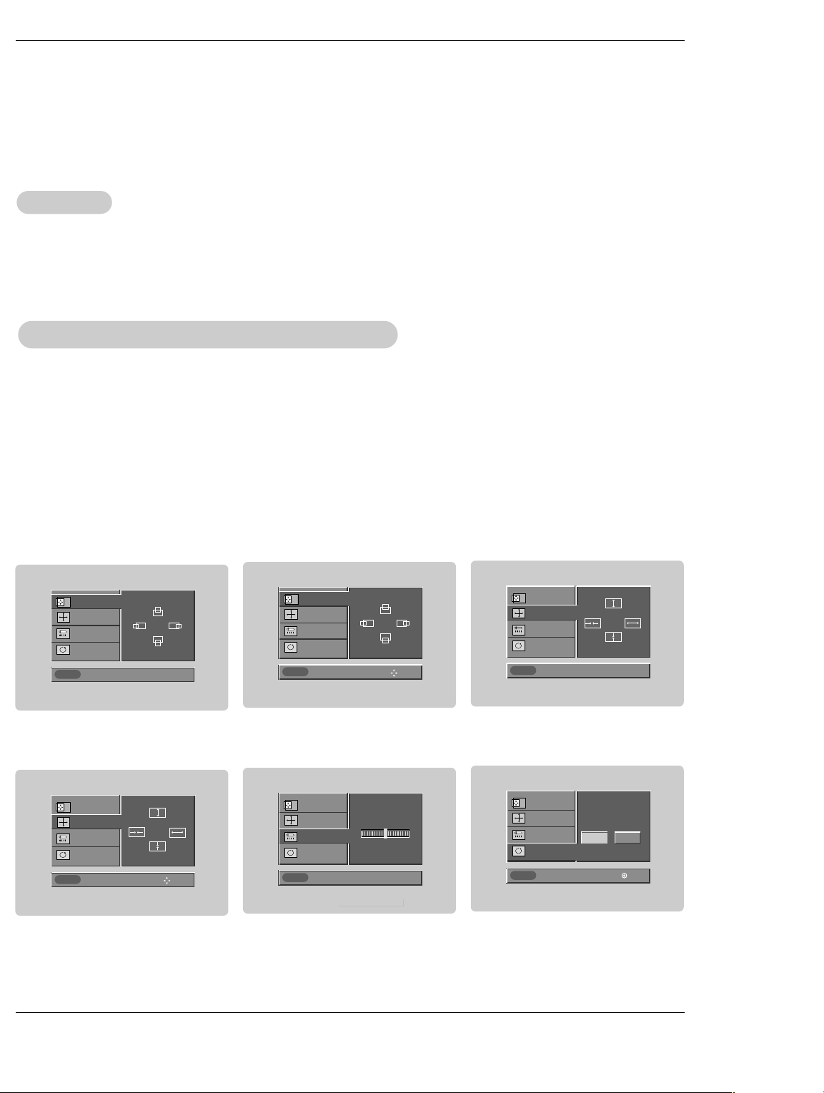
Operation
Screen Setup for PC mode
Operation
Operation
• When RGB connect to PC input and select the RGB-PC in Main Input, this function is used.
• When HDMI/DVI connect to PC input and select HDMI/DVI input, this function is used.
• In RGB-DTV mode, SIZE and PHASE is not available.
Adjustment for screen Position, Size, Phase, Reset
Adjustment for screen Position, Size, Phase, Reset
•After connecting RGB-PC or HDMI/DVI to PC input and checking the screen quality.
- Display PC Adjust Menu using ADJUST button.
- Position : Adjust the screen position. After displaying the Adjust, select the screen position.
- Size : Adjust the screen size.
- Phase : Adjust the phase of Pixel clock.
(Only available in RGB-PC mode)
- Reset : Initializating Size, Position, Phase adjustment .
Adjust
Adjust
POSITION
SIZE
PHASE
RESET
Previous
POSITION
SIZE
PHASE
RESET
Previous
POSITION G
SIZE
PHASE
RESET
Adjust
POSITION
SIZE
PHASE
RESET
Adjust
Close
Previous
D
F
G
E
D
F
G
E
Size
FF
F
Phase 0
POSITION
D
G
E
SIZE G
PHASE
D
F
G
E
RESET
Close
Move
Adjust
POSITION
SIZE
GG
PHASE
Initialize Settings
No Yes
RESET
F
Previous
G
F
Control
Adjust
G
Move Select
Owner’s Manual 4040 DLP Projection TV
Page 42

Programming the Remote
Programming the Remote
Programming the Remote
G The remote is a multi-brand or a universal remote . It can be programmed to operate most remote-controllable devices of
other manufacturers.
Note that the remote may not control all models of other brands.
Programming a code into a remote mode
Programming a code into a remote mode
1. To find out whether your remote can operate the device without programming, turn on the device such as a VCR and press the
corresponding device button on the remote.
After that, press the POWER button. If the device is turned off then it responds properly and the remote need not to be programmed. If not, the remote should be programmed to operate the device. The programming procedures are explained below.
2. Press the MENU and MUTE button continuously at the same time for 2 seconds, the current selected device button will be illuminated.
If you don't press any button for 20 seconds, the light on the device button will be turned off. In that case, you have to repeat from
step 2.
3. Enter code numbers using the number button on the remote by refering the code table on the following pages. When pressing
the button, the light blinks at a time. If the device turned off, the programming is successful.
4. Press the MENU button to store the code. After blinking twice, this code is stored.
5. Test the remote functions to see if the device responds properly. If not, repeat from step 2.
41 DLP Projection TV Owner’s Manual 41
Page 43
Programming Codes
Programming Codes
Programming Codes
VCRs
VCRs
Brand Codes Brand Codes Brand Codes Brand Codes
AIWA 034
AKAI 016 043 046 124
AMPRO 072
ANAM 031 033 103
AUDIO DYNAMICS
BROKSONIC 035 037 129
CANON 028 031 033
CAPEHART 108
CRAIG 003 040 135
CURTIS MATHES 031 033 041
DAEWOO 005 007 010 064
DAYTRON 108
DBX 012 023 039 043
DYNATECH 034 053
ELECTROHOME 059
EMERSON 006 017 025 027
FISHER 003 008 009 010
FUNAI 034
GE 031 033 063 072
GO VIDEO 132 136
HARMAN KARDON
HITACHI 004 018 026 034
INSTANTREPLAY 031 033
JCL 031 033
JCPENNY 012 013 015 033
JENSEN 043
JVC 012 031 033 043
125 146
012 023 039 043
06 5 1 08 11 0 111
112 116 117 119
029 031 034 035
036 037 046 101
129 131 138 153
107 109 144 147
012 045
043 063 137 150
040 066 101
048 050 055 060
130 150 152
KENWOOD 014 034 039 043
LG (GOLDSTAR) 001 012 013 020
LLOYD 034
LXI 003 009 013 014
MAGIN 040
MAGNAVOX 031 033 034 041
MARANTZ 012 031 033 067
MARTA 101
MATSUI 027 030
MEI 031 033
MEMOREX 003 010 014 031
MGA 045 046 059
MINOLTA 013 020
MITSUBISHI 013 020 045 046
MTC 034 040
MULTITECH 024 034
NEC 012 023 039 043
NORDMENDE 043
OPTONICA 053 054
PANASONIC 066 070 074 083
PENTAX 013 020 031 033
PHILCO 031 034 067
PHILIPS 031 033 034 054
PILOT 101
PIONEER 013 021 048
047 048
101 106 114 123
017 034 101 106
067 068
069
033 034 053 072
101 102 134 139
049 051 059 061
151
048
133 140 145
063
067 071 101
PORTLAND 108
PULSAR 072
QUARTZ 011 014
QUASAR 033 066 075 145
RCA 013 020 033 034
REALISTIC 003 008 010 014
RICO 058
RUNCO 148
SALORA 014
SAMSUNG 032 040 102 104
SANSUI 022 043 048 135
SANYO 003 007 010 014
SCOTT 017 037 112 129
SEARS 003 008 009 010
SHARP 031 054 149
SHINTOM 024
SONY 003 009 031 052
SOUNDESIGN 034
STS 013
SYLVANIA 031 033 034 059
SYMPHONIC 034
TANDY 010 034
040 041 062 063
107 109 140 144
145 147
031 033 034 040
053 054 101
105 107 109 112
113 115 120 122
125
102 134
131
013 014 017 020
031 042 073 081
101
056 057 058 076
077 078 149
067
TATUNG 039 043
TEAC 034 039 043
TECHNICS 031 033 070
TEKNIKA 019 031 033 034
THOMAS 034
TMK 006
TOSHIBA 008 013 042 047
TOTEVISION 040 101
UNITECH 040
VECTOR RESEARCH
VICTOR 048
VIDEO CONCEPTS
VIDEOSONIC 040
WARDS 003 013 017 024
YAMAHA 012 034 039 043
ZENITH 034 048 056
101
059 082 112 131
012
012 034 046
031 033 034 040
053 054 131
058 072 080 101
TV
CACATV
Brand Codes Brand Codes Brand Codes Brand Codes
ABC 003 004 039 042
AJIN 112
ANTRONIK 014
ARCHER 005 007 014 024
CABLE STAR 026
CENTURION 092
CENTURY 007
CITIZEN 007
COLOUR VOICE 065 090
COMBANO 080 081
COMTRONICS 019 030
DIAMOND 023
EAGLE 020 030 040
EASTERN 057 062 066
ELECTRICORD 032
GE 072
GEMINI 008 022 025 054
GI 052 074
046 052 053
GOLDEN CHANNEL
HAMLIN 049 050 055
HITACHI 052 055
HOSPITALITY 070 077
JERROLD 002 003 004 008
LG (GOLDSTAR) 001 106 101 005
M-NET 037
MACOM 033
MAGNAVOX 010 012 064 079
MEMOREX 100
MOVIE TIME 028 032
NSC 015 028 038 071
OAK 016 031 037 053
PANASONIC 044 047
PARAGON 100
PHILIPS 006 012 013 020
030
009 010 052 069
074
073
PIONEER 034 051 052 063
POST NEWS WEEK
PRUCER 059
PTS 011 048 071 072
PULSAR 100
RCA 047
REGAL 049 050
REGENCY 057
REMBRANT 025
SAMSUNG 102 107 030 068
SCIENTIFIC ATLANTA
SHERITECH 022
SIGNAL 030
SIGNATURE 052
SL MARX 030
065 085 090
076
016
073 074
003 011 041 042
043 045 046
SPRUCER 047 078
STARCOM 002 004 008 009
STARGATE 008 030
TADIRAN 030
TAEKWANG 110
TAIHAN 105
TANDY 017
TEXSCAN 029
TOCOM 039 040 056
TOSHIBA 100
UNIKA 007 014 024
UNITED CABLE 004 053
UNIVERSAL 005 007 014 024
VIEWSTAR 012 015 018 086
ZENITH 100 114 060 093
026 027 032 035
087 088 089
Owner’s Manual 4242 DLP Projection TV
Page 44
Programming Codes
HDSTB
HDSTB
Brand Codes Brand Codes Brand Codes Brand Codes
ALPHASTAR DSR
AMPLICA 050
BIRDVIEW 051 126 129
CHANNEL MASTER
CHAPARRAL 008 009 012 077
CITOH 054
CURTIS MATHES 050 145
DRAKE 005 006 007 010
DX ANTENNA 024 046 056 076
ECHOSTAR 038 040 057 058
ELECTRO HOME 089
EUROPLUS 114
FUJITSU 017 021 022 027
Audio
Audio
123
013 014 015 018
036 055
011 052 112 116
141
093 094 095 096
097 098 099 100
122
133 134
GENERAL INSTRUMENT
HITACHI 139 140
HOUSTON TRACKER
HUGHES 068
JANIEL 060 147
JERROLD 061
KATHREIN 108
LEGEND 057
LG 001
LUTRON 132
LUXOR 062 144
MACOM 010 059 063 064
MEMOREX 057
NEXTWAVE 028 124 125
NORSAT 069 070
003 004 016 029
031 059 101
033 037 039 051
057 104
065
PACE SKY SATELLITE
PANASONIC 060 142
PANSAT 121
PERSONAL CABLE 117
PHILIPS 071
PICO 105
PRESIDENT 019 102
PRIMESTAR 030 110 111
PROSAT 072
RCA 066 106
REALISTIC 043 074
SAMSUNG 123
SATELLITE SERVICE CO
SCIENTIFIC ATLANTA
SONY 103
STARCAST 041
SUPER GUIDE 020 124 125
TEECOM 023 026 075 087
143
028 035 047 057
085
032 138
088 090 107 130
TOSHIBA 002 127
UNIDEN 016 025 042 043
VIEWSTAR 115
WINEGARD 128 146
ZENITH 081 082 083 084
137
044 045 048 049
078 079 080 086
101 135 136
091 120
Brand Codes Brand Codes Brand Codes Brand Codes
AIWA 014 028 070 096
AKAI 163
ANAM 003 014 017 023
BURMECTER 252
CARVER 086
CLARION 199
DAEWOO 027 053 060 084
DENON 015 075 130 143
FANTASIA 071
FINEARTS 022
FISHER 089 099
LG(GOLDSTAR) 001 021 024 029
HAITAI 034 035 188 222
HARMAN/KARDON 068
INKEL 037 058 062 069
DVD
DVD
Brand Codes Brand Codes Brand Codes Brand Codes
APEX DIGITAL 022
DENON 020 014
GE 005 006
HARMAN KARDON 027
JVC 012
LG 001 010 016 025
125 129 139 229
230
059 106 189 216
217 235 236
102 148 198 221
087 107 108 110
190 191 192 210
211 212 239
078 079 095 121
122 149 150 151
152 153 154 155
157 158 159 160
189 207 222 224
225 226 227 243
247
JVC 004 013 141
KEC 185 186 187
KENWOOD 038 050 067 089
KOHEL 030
NAD 045 046
LOTTE 014 016 036 098
LXI 103
MAGNAVOX 111
MARANTZ 002 018 020 025
MCINTOSH 049
MCS 104
MEMOREX 107
NAD 046
ONKYO 013 040 041 047
OPTIMUS 158
PANASONIC 007 033 064 113
PENNEY 104
MAGNAVOX 013
MARANTZ 024
MITSUBISHI 002
NAD 023
ONKYO 008 017
PANASONIC 003 009
170 171 197 206
215 222
100 172 173 174
175 176 177 178
179 180 181 183
201 202 208 213
214 219 223 232
238 240
034 041 081 090
097 112
048 056 057 132
133 140
142 220 241 251
PHILIPS 026 112 143
PIONEER 039 042 043 063
QUASAR 113
RCA 080
RCX 092
REALISTIC 103 106
SAMSUNG 124 145 146 182
SANSUI 011 135 138 144
SANYO 019 083 234
SCOTT 106 186
SHARP 031 032 051 052
SHERWOOD 005 006 158
SONY 044 045 109 114
TAEKWANG 012 020 073 074
TEAC 010 085 106 136
TECHNICS 101 113 128 134
PHILIPS 013
PIONEER 004 026
PROCEED 021
PROSCAN 005 006
RCA 005 006
SAMSUNG 011 015
065 091 093 094
115 123 127 250
193 194 195 203
204 244 245 246
072 082 117 119
156 184 199 200
206 209
118 126 248 249
076 077 105 161
162 163 164 165
166 167 168 169
205 231 233 242
185 187 237
TOSHIBA 137
THE 061
VICTOR 088 131
WARDS 089
YAMAHA 054 055 066 092
SONY 007
THOMPSON 005 006
TOSHIBA 019 008
YAMAHA 009 018
ZENITH 010 016 025
147 218
199
43 DLP Projection TV Owner’s Manual 43
Page 45
Troubleshooting Checklist
roubleshooting Checklist
TTroubleshooting Checklist
• Check whether the TV is turned on.
No picture &
No sound
Picture OK &
No sound
The remote control
doesn’t work
Picture appears slowly
after switching on
• Is the power cord inserted into wall power outlet?
• Test the wall power outlet, plug another product’s power cord into the outlet
where the TV’s power cord was plugged in.
• Press the VOLUME (G) button.
• Sound muted? Press MUTE button.
• Check to see if there is any object between the TV and the remote control
causing obstruction.
• Are batteries installed with correct polarity (+ to +, - to -)?
(Refer to p.11)
• Correct remote operating mode set: TV, VCR etc.?
• Install new batteries. (Refer to p.11)
• This is normal, the image is muted during the TV startup process. Please
contact your service center, if the picture has not appeared after five minutes.
No or poor color
or poor picture
Horizontal/vertical bars
or picture shaking
•Select Color in the Picture menu and press the G button.
(Refer to p.62)
• Keep a sufficient distance between the TV and the VCR.
• Activate any function to restore the brightness of the picture.
(If still picture is on the screen for more than 5 minutes, the screen gets dark.)
• Check for local interference such as an electrical appliance or power tool.
Owner’s Manual 4444 DLP Projection TV
Page 46
Troubleshooting Checklist
No output from one of
the speakers
Unusual sound from
inside the TV
Poor TV input
signal
Poor Video
signal
• Adjust Balance in the AUDIO menu. (Refer to p.63)
• A change in ambient humidity or temperature may result in the unit turning off
and does not indicate a fault with the TV.
• Check ANTENNA and CABLE connection.
• Check ANTENNA and CABLE connection.
No channel or a few
• Start EZ Scan.
channel
Unsuitable
Aspect Ratio
• You can adjust the RATIO button or Aspect Ratio in the OPTION menu.
My Guide listings
disappeared after a power
• You should begin to receive listings again within 24 hours.
failure
45 DLP Projection TV Owner’s Manual 45
Page 47
Troubleshooting Checklist
roubleshooting Checklist
TTroubleshooting Checklist
Some channel numbers
in the Guide are incor-
rect.
I have not received any
Guide listings.
A show I set to Record
did not occur.
• You can correct them using Change Channel Display under Setup.
• Listings usually appear within 24 hours after a successful Setup.
• It may take up to a week to fill the Listings grid with the full 8 days of listings.
• If you see a Listings grid with the message "No Listings" displayed you should
start to receive updated program listings within 24 hours. To receive listings:
W
Make sure the cable box is left On, if applicable.
W
Turn off your recorder when not in use.
• If the message "No data for this screen" is displayed:
W
Check the connections between the TV, cable, antenna, and the IR cable
if using a cable box.
W
Verify Setup information under Change System Settings.
W
Make sure the cable box is On, if applicable.
W
If this message is still displayed after multiple days, please contact the
LG® Brand Customer Support.
• Make sure your recorder is turned Off before the recording begins.
• Make sure there is a tape.
• Check the Schedule menu and verify that the show is listed before recording
begins.
• Check the placement of the IR cable in front of your recorder.
I set a show to Auto-Tune
and it did not.
I set a show with the
Power On TV option and
it did not.
• Check the Schedule menu and verify that the show is listed as a Reminder.
• Highlight the show under Listings and do the following:
W
Press the Menu key on the remote.
W
Use the down arrow to highlight Edit Reminder, and press ENTER.
W
Verify the Auto-Tune option reads Yes.
• The TV must be On at the scheduled time for Auto-Tune.
• If you have a cable box, check the IR cable.
• Check the Schedule menu and verify that the show is listed as a Reminder.
• Highlight the show under Listings and do the following:
W
Press the Menu key on the remote.
W
Use the down arrow to highlight Edit Reminder, and press ENTER.
W
Verify the Power On TV option reads Yes.
Owner’s Manual 4646 DLP Projection TV
Page 48
Maintenance
Maintenance
- Early malfunctions can be prevented. Careful and regular cleaning can extend the amount of time you will have your
new TV. Be sure to turn the power off and unplug the power cord before you begin any cleaning.
Cleaning the Screen
Cleaning the Screen
1. Here’s a great way to keep the dust off your screen for a while. Wet a soft cloth in a mixture of lukewarm water and
a little fabric softener or dish washing detergent. Wring the cloth until it’s almost dry, and then use it to wipe the
screen.
2. Make sure the excess water is off the screen, and then let it air-dry before you turn on your TV.
Cleaning the Cabinet
Cleaning the Cabinet
To remove dirt or dust, wipe the cabinet with a soft, dry, lint-free cloth.
Please be sure not to use a wet cloth.
Maintenance
Extended
Extended
Absence
Absence
If you expect to leave your TV dormant for a long time (such as a vacation), it’s a good idea to unplug
the power cord to protect against possible damage from lightning or power surges.
47 DLP Projection TV Owner’s Manual 47
Page 49
Product Specification
Product Specifications
Product Specifications
MODEL
Horizontal Size (inches)
Height (inches)
Depth (inches)
Weight (lbs.)
Power requirement
Television System
Program Coverage
Power Consumption (W)
Antenna
Audio Output (W)
Supplied Accessories
Z44SZ80
39.2
29.2
14.4
50.7
AC120V ~ 60Hz
NTSC-M, ATSC, 64 & 256 QAM
VHF 2 ~ 13, UHF 14 ~ 69, CATV 1 ~ 135, CADTV 1 ~ 135. DTV 2 ~ 69
210W
75 ohm External Terminal for VHF/UHF
20Wx2
Remote control, 2 size AA batteries, D-sub 15 pin Cable
Z52SZ80
47.5
33.8
15.7
66.1
• The specifications shown above may be changed without prior notice for quality improvement.
48 DLP Projection TV
 Loading...