

LG 42PX5D - 42 Plasma Integrated HDTV, 42PX4D, 42PX5D, 42PX4D-UB, 42PX5D-UB Owner's Manual

1:2 _ _4i /
.OD_LS: 4zPX D,4 _PX5D
42PX4DoUB/42PX5D-U8
DI GITAL X_r_,o
Please read thus manual careiully and completely betore
operating your TV
Retain this Inanual for future reference
Record model number and senal number o_ _he TV in _he
spaces p_osqded belo_.
See tile label attsched on the back cover and relate _hus
mrfformatmonto your dealer m[you requue set!ice
Model Number "
Serial Number
Warning/Caution
WARNING/CAUTION
WARNiNG/CAUTiON:
TO REDUCE THE RISK OF ELECTRIC SHOCK DO NOT REMOVE COVER (OR BACK), NO USER
SERVICEABLE PARTS INStDE, REFER TO QUALIFIED SERVICE PERSONNEL,
,_ The lightning flash with arrowhead symbo!, within an equilateral triangle, is intended to alert the user to
the presence of uninsulated "dangerous voltage" within the product's enclosure that may be of suffi-
cient magnitude to constitute a risk of electric shock to persons,
,_ The exclamation point within an equilateral triangle is intended to alert the user to the presence of
important operating and maintenance (servicing) instructions in the literature accompanying the appli-
ance,
WARNiNG/CAUTiON:
TO PREVENT FIRE OR SHOCK HAZARDS, DO NOT EXPOSE THIS PRODUCT TO RAtN OR MOISTURE,
FCC NOTICE
A Ctass B digitam device
This equipment has been tested and found to comply with the limits for a Class B digital device, pursuant to Part
15 of the FCC Rules, These limits are designed to provide reasonable protection against harmful interference in
a residential installation, This equipment generates, uses and can radiate radio frequency energy and, if not
installed and used in accordance with the instructions, may cause harmful interference to radio communications,
However, there is no guarantee that interference will not occur in a particular installation, If this equipment does
cause harmful interference to radio or television reception, which can be determined by turning the equipment off
and on, the user is encouraged to try to correct the interference by one or more of the following measures:
- Reorient or relocate the receiving antenna,
- Increase the separation between the equipment and receiver,
- Connect the equipment into an outlet on a circuit different from that to which the receiver is connected,
- Consult the dealer or an experienced radio/TV technician for help,
o Any changes or modifications not expressly approved by the party responsibme for compmi-
ance could void the user's authority to operate the equipment,
Do not attempt to modify this product in any way without written authorization from LG Electronics, Unauthorized mod-
ification could void the user's authority to operate this product,
COMPLIANCE:
The responsible party for this product's compliance is:
LG Electronics U.S.A, Inc
1000 Sylvan Avenue, Englewood Cliffs, NJ 07632
! -800-243-0000
http://w_Jv.lgu sa.com
J
WARNmNG/CAUTION
TO REDUCE THE RISK OF FIRE AND ELECTRIC SHOCK, DO NOT EXPOSE THIS PRODUCT TO
RAIN OR MOISTURE,
2 Plasma TV

Trademark Notice
In the United States, TV GUIDE and other related marks are registered marks of Gemstar-TV Guide International, Inc. and/or
one of its affiliates. In Canada, TV GUIDE is a registered mark of Transcontinental Inc., and is used under license by
Gemstar-TV Guide International, Inc.
Aux Etats Unis TV GUIDE et d'autres marques relatives sont des marques d_pos_es de Gemstar-TV Guide International,
Inc. et/ou d'une de ses soci6t6s affili6es. Au Canada TV GUIDE est une marque d_posee de Transcontinental Inc., utilis6e
sous licence de Gemstar-TV Guide International, Inc.
License Notice
The TV Guide On Screen system is manufactured under license from Gemstar-TV Guide International, Inc. and/or one of its
affiliates.
Le syst6me TV Guide On Screen est fabriqu6s sous licence de Gemstar-TV Guide International, Inc. et/ou d'une de ses soci_t_s
affiliees.
Patent Notice
The TV Guide On Screen system is protected by one or more of the following issued United States patents 8,498,898,
8,418,588, 8,331,877; 8,239,794; 8,184,203; 8,940,073; 4,908,713; 4,781,578; 4,706,121.
Le syst_me TV Guide On Screen est proteges par un ou plusieurs brevets _mis aux Etats Unis, comme le 6,498,898,
6,418,886, 6,331,877; 8,239,794; 8,154,203; 5,940,073; 4,908,713; 4,751,878; 4,708,12!.
Tbl
Use of the CableCARD TradeMark.
"CableCARD TM is a trademark of Cable Television Laboratories, Inc."
This digital television is capable of receiving basic ana!og, digital basic and digital premium cable television programming by
direct connection to a cable system providing such programming. A security card provided by your cable operator is required
to view encrypted digital programming. Cable operator enhanced program (For example, electronic program guide provided
by the cable operator), and data enhanced television service may require the use of a set top box. For more information con-
tact your local cable operator.
Owner's Manual 3

Safetyinstructions
iMPORTANT SAFETY iNSTRUCTiONS
important safety instructions shall be provided with each apparatus. This information shall be given in a separate booklet or
sheet, or be located before any operating instructions in an instruction for installation for use and supplied with the appara-
tus. This information shall be given in a language acceptable to the country where the apparatus is intended to be used. The
important safety instructions sha!l be entitled "important Safety Instructions". The fo!lowing safety instructions sha!l be includ-
ed where applicable, and, when used, shall be verbatim as follows. Additional safety information may be included by adding
statements after the end of the following safety instruction list. At the manufacturer's option, a picture or drawing that illus-
trates the intent of a specific safety instruction may be placed immediately adiacent to that safety instruction :
1. Read these instructions.
2. Keep these instructions.
3. Heed all warnings.
4. Follow all instructions.
5. Do not use this apparatus near water.
6. C_ean only with dry cloth.
7. Do not block any ventilation openings. Install in accordance with the manufacturer's instructions.
8. Do not install near any heat sources such as radiators, heat registers, stoves, or other apparatus (incmuding ampH-
tiers}that produce heat.
9. Do not defeat the safety purpose of the polarized or grounding-type p_ug. A pomarized p_ug has two blades with
one wider than the other. A grounding type p_ug has two blades and a third grounding prong, The wide blade or the
third prong are provided for your safety. If the provided p_ug does not fit into your outlet, consult an electrician for
replacement of the obsolete outlet.
10. Protect the power cord from being walked on or pinched particularly at p_ugs, convenience receptacles, and the
point where they exit from the apparatus.
11. Only use attachments/accessories specified by the manufacturer.
12. Use only with the cart, stand, tripod, bracket, or table specified by the manufacturer, or sold with the apparatus.
When a cart is used, use caution when moving the cart/apparatus combination to avoid injury from tip=over.
Q
PORTABLE CART WARNING
J
4 Plasma TV

Safetyinstructions
J
13. Unplug this apparatus during _ightning storms or when unused for _ong periods of time.
14. Refer aH servicing to qualified service personnel Servicing is required when the apparatus has been damaged
in any way, such as power_supp_y cord or p_ug is damaged, _iquid has been spilled or objects have fallen into
the apparatus, the apparatus has exposed to rain or moisture, does not operate normally, or has been dropped.
15. CAUTION concerning the Power Cord :
Most appliances recommend they be p_aced upon a dedicated circuit; that
is, a singme out_et circuit which powers only that appliance and has no
additiona_ out_ets or branch circuits. Check the specification page of
this owner's manua_ to be certain.
Do not ovedosd wall out_ets. Overloaded wall out_ets, _oose or damaged
wall out_ets, extension cords, frayed power cords, or damaged or
cracked wire insulation are dangerous. Any of these conditions could
result in e_ectric shock or fire. Periodically examine the cord of your
appliance, and if its appearance indicates damage or deterioration,
unplug it, discontinue use of the appliance, and have the cord replaced
with an exact replacement part by an authorized servicer.
Protect the power cord from physiea_ or mechanica_ abuse, such as being
twisted, kinked, pinched, c_osed in a door, or walked upon. Pay
particular attention to pmugs,wall out_ets, and the point where the
cord exits the appliance.
16. Outdoor Use Marking :
WARNING - To Reduce The Risk Of Fire Or E_ectrie Shock, Do Not Expose This Appliance To Rain Or Moisture.
17. Wet Location Marking :
Apparatus shah not be exposed to dripping or splashing and no objects filled with _iquids, such as vases, shah
be p_aced on the apparatus.
\
J
Owner_Manua/ 5
Contents
Warning/Caution ................................ 2
Digital Cable Compatibility ......................... 3
Safety Instructions ............................. 4-5
Introduction
Controls ............................... 8
Connection Options ...................... 9
Remote Control Key Functions .......... 10-11
Installation
Accessories ............................. 12
Installation Instructions .................. 12~ 13
Joining the TV assembly to the wallto protect the set turn+
bling ................................. 12
Swivel function .......................... 13
External Equipment Connections .......... 14- ! 9
Antenna or Cable Connection ........... 14~15
VCR Setup ........................... 15
External A/V Source Setup ................ 16
DVD Setup ............................ 16
CabbCARD TM Setup ..................... 17
HDSTB Setup ......................... 17
PC Setup ............................. 18
Monitor Out Setup ...................... 19
Digital Audio Output ..................... 19
HDMI ............................... 20-22
TV Guide On Screen Setup .............. 23-32
tEEE 1394 ................................ 33-40
TV Guide On Screen TM System ............. 41~59
Operation
Turning the TV On ........................ 60
TV Setup
On-screen Menus Language Ssbction ....... 61
Setup Menu Options
EZ Scan (Channsl Search) ................ 62
Manual Scan .......................... 62
Channel Edit ........................... 63
DTV Signal Strength ..................... 63
Channel Label Setup .................... 64
Main Picture Source Ssbction ............. 64
Input Label ............................ 64
Video Menu Options
EZ Picture ........................... 65
Manual Picture Control (Custom Option) ...... 65
Color Temperature Control ................ 65
Video Reset ........................... 65
Audio Menu Options
Audio Language ........................ 66
EZ SoundRite / EZ Sound ................. 66
Manual Sound Control (Custom Option) ...... 66
Front Surround ......................... 67
Set:u p and
TV Speakers On/Off Setup ................ 67
BBE ................................ 68
Stereo/SAP Broadcasts Setup .............. 68
Tims Menu Options
Auto Clock Setup ....................... 69
Manua! Clock Setup ..................... 69
On/Off Timer Setup ..................... 69
Sleep Timer / Auto Off .................... 70
Option Menu Features
Aspect Ratio Control ..................... 71
Cinema 3:2 Mode Sstup .................. 71
Caption ............................... 72
Caption / Text .......................... 72
Caption Option ........................ 73
ISM Method ........................... 74
Low Power ............................ 75
Auto Dsmo ........................... 75
Lock Menu Options
Lock Menu Options ...................... 76
Parental Lock Setup ..................... 77
CabbCARD TM Function
Cable menu options ..................... 78
Scrambled channel ...................... 78
Cable Channel List ...................... 79
Emergency Alert Message ................ 79
XSTUO_O ......................... 80~85
Remote Control
PIP (Picture-in+Picture)/POP/Twin Picture ....... 86
Watching PIP/POP/Twin Picture ............. 86
Selectingan Input Signal Source for PIP/TwinPicture..86
Swapping PIP/Twin Picture ................ 86
TV Program Selection for PtP .............. 86
Moving the PIP sub picture ................ 87
AdjustingMain and SubPictureSizes forTwin Picture. ,87
POP(Picture-out-of-Picture: Channe! Scan) .... 87
APM(Adaptiva Picture Mode) ................ 88
Brief Info ................................ 89
EZ Mute ................................ 90
Freeze & Magnify ......................... 90
Scresn Setup for PC mode .................. 91
Externa_ Contro_ Device Setup ................ 92~97
IR Codes ................................ 98~99
Programming the Remote ..................... 100
Programming Codes ..................... 101 ++102
TrouMeshooting ChesMist ..................... 103
Maintenance ................................ 104
Product Specifications ........................ 105
Warranty ............................... 107+408
Operation Checklist
Setup and Operation Chscklist
(Sse pages 14-19 for availab!e connection and operational setup options.)
f. Unpack TV and all accessories. 5. Turn vidso source squipment on.
2. Connect all external video and audio equipmsnt.
see pages 15-19.
6. Select viewing source for TV.
See pages 64.
3 Install batteries in remote control.
See page 11.
4. Turn TV on.
See page 60.
7. Fine-tune source image and sound to your personal prefer-
ence or as required by source.
Ses pages 65~ 68.
8. Additional features set up
See Contents above.
6 Plasma TV
After rsading this manual, keep it handy for future reference.

introduction
What is a Plasma Display Panem (PDP)?
A plasma display panel is the latest display technology and the best way to achieve flat panel displays with excellent image quality
and large screen sizes that are easily viewab]ea The PDP can be thought of as a descendant of the neon lamp and it can be also
be viewed as a series of fluorescent lampSa
How does it work?
PDP is an array of ceils, known as pixels, which are comprised of 3 sub pixels, corresponding to the colors red, green, and blUea
Gas in a plasma state is used to react with phosphors in each sub-pixel to produce colored light (red, green, or blUe)a These phos-
phors are the same types used in Cathode Ray Tube (CRT) devices such as televisions and common computer monitors,
You get the rich, dynamic colors that you expect, Each sub-pixet is individually controlled by advanced electronics to produce over
16 million different CoIOrSaAll of these mean that you get perfect images that are easily viewable in a display that is less than 5
inches thick,
160 ° = Wide angle range of vision
Your flat pane! plasma screen offers an exceptionally broad viewing angle -- over 160 degrees, This means that the display is
clear and visible to viewers anywhere in the room who can see the screen,
Wide Screen
The screen of the Plasma Display is so wide that your viewing experience is as if you are in a theater,
Mumtimedia
Connect your plasma display to a PC and you can use it for conferencing, games, and Intemet browsing, The Picture-in-Picture
feature allows you to view "our PC and video images simultaneouSlya
Versatime
The light weight and thin size makes it easy to install your plasma display in a variety of locations where conventional TVs will not
fita
The PDP Manufacturing Process: a few minute colored dots may be present on the PDP screen
The PDP (Plasma Display Panel), which is the display device of this product, is composed of 0=9 to 2=2 million ceils= A few cell
defects will normally occur in the PDP manufacturing process= Several tiny, minute colored dots visible on the screen should be
acceptable= This also occurs in other PDP manufacturers' products= The tiny dots appearing does not mean that this PDP is defec-
tive= Thus a few cell defects are not sufficient cause for the PDP to be exchanged or returned= Our production technology mini-
mizes these cell defects during the manufacture and operation of this product=
Owner_Manuaf 7

Introduction
- This is a simplified representation of a front panel.
- Here shown may be somewhat different from your TV.
i:- "-iT-.
(... 42PX5D .)
-1
(i 42PXaD [)
1
mNBEX
-- Switches
LED
Display on
or off=
Remote Contro_
Sensor
L_C ANL_N Power Standby mndicator
illuminates orange in
B EL (_', A) Buttons standby mode.
When the TV is turned on,
VOLUME (4,_) Buttons the indicator will blink
MENU Button green for 3-4 seconds
TV/VIDEO Button before the picture is seen.
TV GUIDE Button
POWER Button
8 Plasma TV
introduction
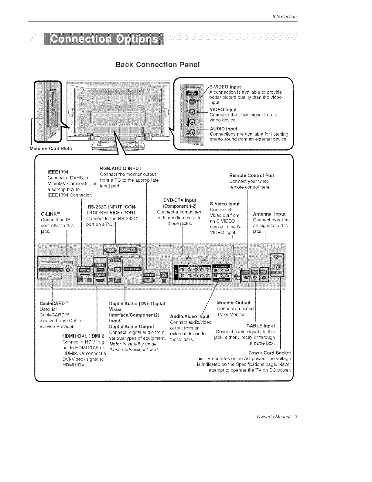
Back Connection Pane_
mnput
connection is available to provide
better picture quality than the video
input.
VIDEO mnput
Connects the video signal from a
video device.
BGB/AUDIO mNPUT
IEEE1394
Connect the monitor output
Connect a DVHS, a from a PC to the appropriate
MicroMV Camcorder, or input port.
a set-top box to
IEEE1394 Connector.
G.LmNKTM
Connect an IR
controller to this
jack.
RS-232C INPUT (CON-
TROL/SERVICE} PORT
Connect to the RS-232C
port on a PC.
DVD/DTV Input
(Component 1-2)
Connect a component
video/audio device to
these jacks.
Remote Contro_ Port
Connect your wired
remote control here.
S-Video mnput
Connect S-
Video out from
an S-VIDEO
device to the S-
VIDEO input.
Antenna Input
Connect over-the-
air signals to this
CaMeCARD TM
Used for
CableCARD TM
received from Cable
Service Provider.
NBMN/DVm, HDMI 2
Digita_ Audio (DVI: Digita_
Visual
Interface/Component2) Audio/Video mn it
input/ Connect audio/video
Digita_ Audio Output output from an
Connect digital audio from external device to
various types of equipment, these iacks.
Connect a HDMI sig- Note." In standby mode,
nal to RDMil/DVI or these ports wifl not work.
HDMI2. Or connect a
DVI(Video) signal to
HDMI1/DVI.
Monitor Output
Connect a second
TV or Monitor.
CABLE Input
Connect cable signals to this
jack, either directly or through
a cable box.
Power Cord Socket
This TV operates on an AC power. The voltage
is indicated on the Specifications page. Never
attempt to operate the TV on DC power.
Owner's Manual 9

/nstallation
- When using the remote control, aim it at the remote control sensor on the TV.
POWER .
Turns your TV or any other programmed
equipment on or off, depending on mode.
Selects the remote operating mode: TV,
DVD, VCR, AUDIO, CABLE or STB. Select
a mode other than TV, for the remote to
operate an external device.
MENU
Brings up the main menu to the screen.
Enters or exits a Panel Menu inthe TV Guide
On Screen system.
EXIT
Clears all on-screen displays and returns to
TV viewing from any menu.
MUTE
Switches the sound on or off.(Refer to p.90)
TIMER \
Lets you select the amount of time before
your TV turns itself off automatically. \.
ADJUST
Ad}usts screen position, size, and phase in
PC mode.
EZ P[C
Selects a factory preset picture mode
depending on the viewing environment.
Freezes the currently-viewed picture. Main
picture is frozen in PIPfTwin picture mode.
TV/V[DEO
put modes rotate in regular
sequence: Antenna, Cable, Video, Front
Video, Component 1-2, RGB-DTV (or
RGB-PC), HDMI!/DVI and HDMI2 input
sources.
(Video, Front Video, Component 1-2 input
sources are linked automatically, only if
these are connected )
TV GUIDE
Brings up the TV Guide On Screen sys-
tem to the screen.
Mark
Selects a photo or music you want to
view or play in Xstudio mode.
" - FAV
Scrolls the Favorite channels.
.....FLASHBK
J"" Tunes to the recent channels.
PIP
Switches to PiP, POP (Picture-out-of-
Picture) and Twin picture modes in regu-
lar sequence.
Switches the video window locking or
unlocking in the Listings Grid.
P[PCR-/P[PCH+
Changes to the next higher/lower PIP
channel.
PIP INPUT
Selects the input source for the sub pic-
ture in PiP/Twin picture mode.
SWAP
Exchanges the main/sub images in
picture mode,
Starts the demonstration to explain the main
features of this TV.
UGRT
Illuminates the remote control
buttons of selected mode.
I0 Plasma TV
Installation
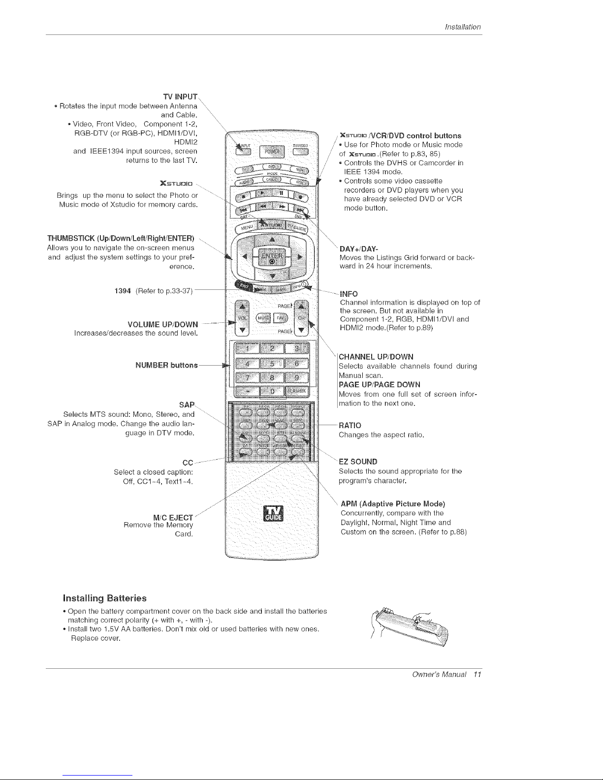
TV mNPUT
\
Rotates the input mode between Antenna
and Cable.
Video, Front Video, Component 1-2,
RGB-DTV (or RGB-PC), HDMI!/DVi,
HDMi2
and IEEE1394 input sources, screen
returns to the last TV.
N
x
x
x
]_STUFJI[_
Brings up the menu to select the Photo or
Music mode of Xstudio for memory cards.
THUMBSTICK (Up/Down/Left/Right/ENTER)
Allows you to navigate the on-screen menus
and adjust the system settings to your pref-
erence.
1394 (Refer to p.33-37)
VOLUME UP/DOWN
Increases/decreases the sound level
NUMBER
SAP ........
Selects MTS sound: Mono, Stereo, and ...........
SAP in Analog mode. Change the audio lan-
guage in DTV mode.
CC
Select a closed caption:
Off, CC1 ~4, Text1 ~4.
M/C EJECT
Remove the Memory
Card.
, XSTUUmO/VCR/DVD contro_ buttons
J • Use for Photo mode or Music mode
," of XsTurJl_.(Refer to p.83, 85)
,; • Controls the DVHS or Camcorder in
IEEE 1394 mode.
Controls some video cassette
recorders or DVD players when you
have already selected DVD or VCR
mode button.
"DAY+/DAY-
Moves the Listings Grid forward or back-
ward in 24 hour increments.
...... INFO
Channel information is displayed on top of
the screen. But not available in
Component 1-2, RGB, HDMI1/DVI and
HDMI2 mode.(Refer to p.89)
CHANNEL UP/DOWN
Selects availabb channels found during
Manual scan.
PAGE UP/PAGE DOWN
Moves from one full set of screen infor-
mation to the next one.
Changes the aspect ratio.
EZ SOUND
Selects the sound appropriate for the
program's character.
APM (Adaptive Picture Mode}
Concurrently, compare with the
Daylight, Normal, Night Time and
Custom on the screen. (Refer to p.88)
Installing Batteries
Open the battery compartment cover on the back side and install the batteries
matching correct polarity (+ with +, - with -).
Install two 1.5V AA batteries. Don't mix old or used batteries with new ones.
Replace cover.
Owner's Manual 11
/nstalladon
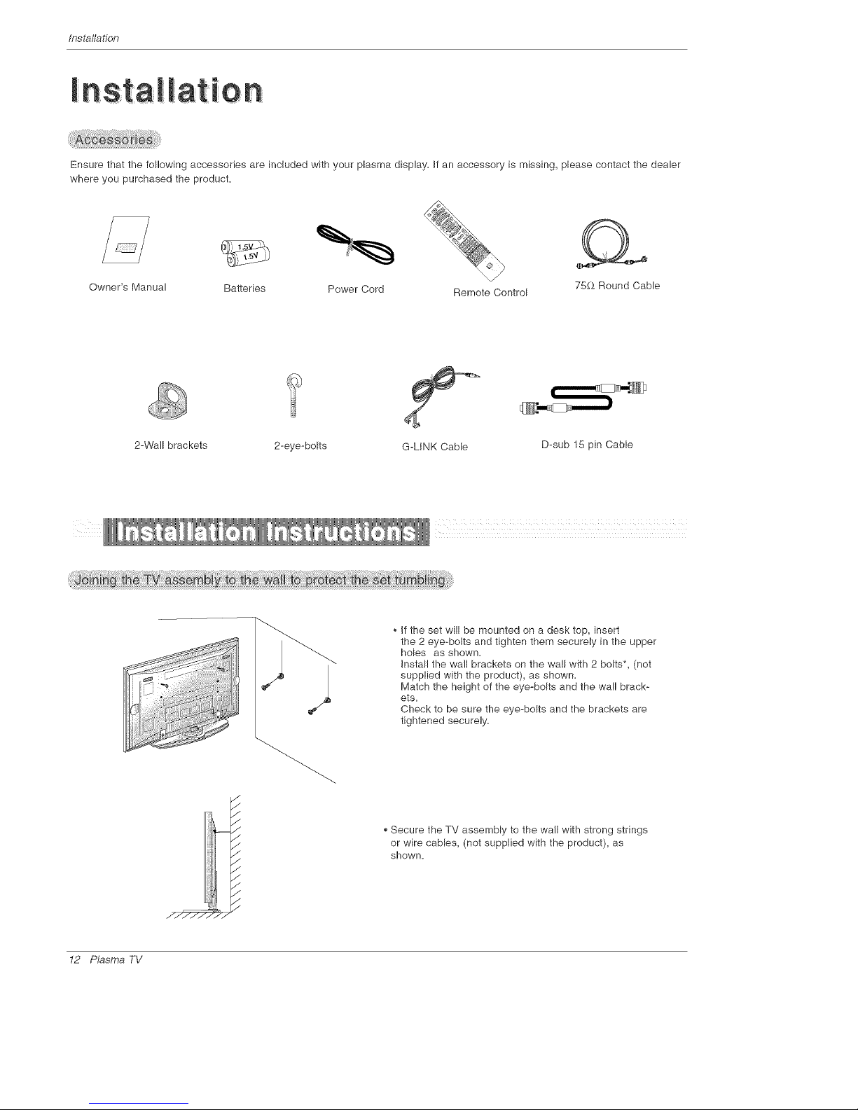
Ensure that the following accessories are included with your plasma display. If an accessory is missing, please contact the dealer
where you purchased the product.
Owner's Manual Batteries Power Cord Remote Control 75£_ Round Cable
2-Wall brackets 2-eye-bolts
D-sub 15 pin Cable
/
/
,/
/
./
,/
/
,/
.//_ >/-
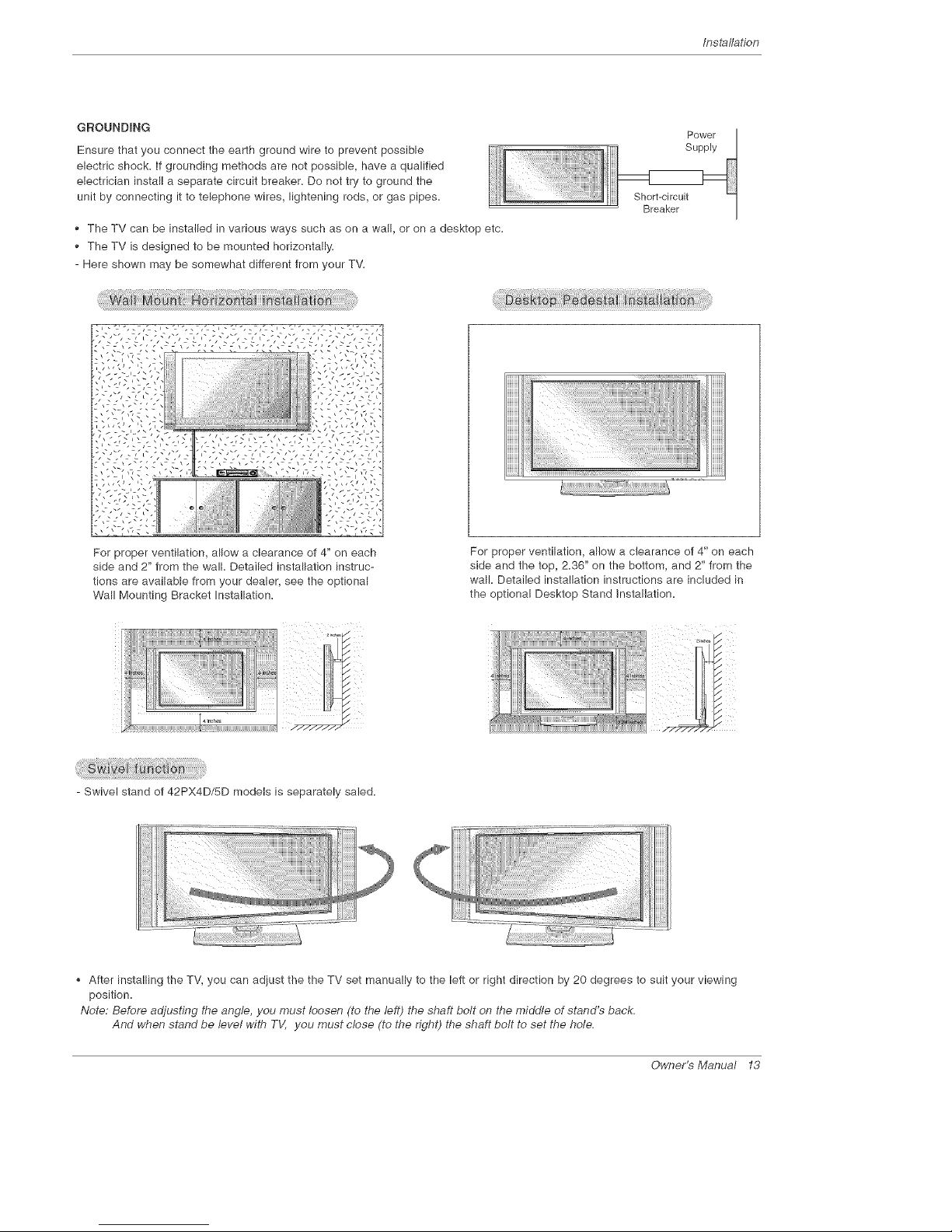
,, If the set will be mounted on a desk top, insert
the 2 eye-bolts and tighten them securely in the upper
holes as shown.
InstaWthe wall brackets on the wa!l with 2 bolts*, (not
supplied with the product), as shown.
Match the height of the eye-bolts and the wall brack-
ets.
Check to be sure the eye-bolts and the brackets are
tightened securely.
,,Secure the TV assembly to the wall with strong strings
or wire cables, (not supplied with the product), as
shown.
12 Plasma TV
Installation
GROUNDING
Ensure that you connect the earth ground wire to prevent possible
electric shock, if grounding methods are not possible, have a qualified
electrician install a separate circuit breaker. Do not try to ground the
unit by connecting it to telephone wires, lightening rods, or gas pipes.
The TV can be installed in various ways such as on a wall, or on a desktep etc.
The TV is designed to be mounted horizontally.
- Here shown may be somewhat different from your TV.
Power
Supply
Short-circuit
Breaker
t ..... ,zz,c:".',_z,._"-',zz,c:".',_z,._"l
For proper ventilation, allow a clearance of 4" on each
side and 2" from the wall. Detailed installation instruc-
tions are available from your dealer, see the optional
Wall Mounting Bracket Installation.
For proper ventilation, allow a clearance of 4" on each
side and the top, 2.36" on the bottom, and 2" from the
wall. Detailed installation instructions are included in
the optional Desktop Stand installation.
- Swivel stand of 42PX4D/SD models is separately saled.
After installing the TV, you can adiust the the TV set manually to the left or right direction by 20 degrees to suit your viewing
position.
Note: Before adjusting the angle, you must loosen (to the left) the shaft bolt on the middle of stand's back.
And when stand be level with TV, you must close (to the right) the shaft bolt to set the hole.
Owner's Manual 13

/nstalladon
1. Analog and Digitam TV eigname provided on antenna
- Wall Antenna Socket or Outdoor Antenna without a Cable Box Connection
- For optimum picture quality, adjust antenna direction if needed,
Multi-family Dwellings/Apartments
(Connect to wall antenna socket)
Wall Antenna
Socket
VHF Antenna
UHF Antenna
Outdoor
Antenna
Bronze Wire
f
Turn clockwise to tighten,
s/Houses
(Connect to wall jack for outdoor antenna)
Bronze Wire
Be careful not to bend the bronze wire when
connecting the antenna,
J
J
2. Analog and Digita_ TV signals provided on cabme
j-
CableTV Wall
Turn clockwise to tighten,
_J
I4 Plasma TV
Installation
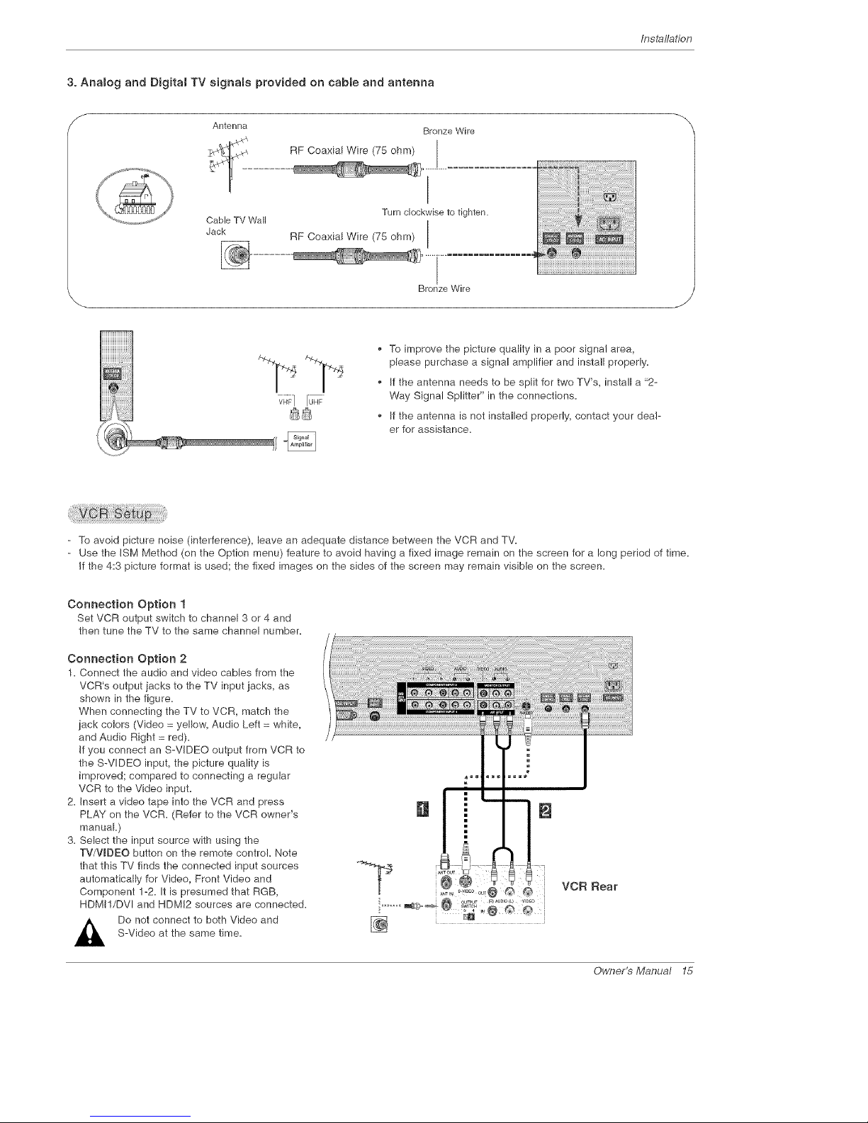
3. Anamog and Digitat TV signals provided on cable and antenna
f
Antenna
Cable TV Wall
Jack
Bronze Wire
Turn clockwiseto tighten.
RF Coaxial Wire (75 ohm)
Bronze Wire
_J
• To improve the picture quality in a poor signal area,
please purchase a signal amplifier and install properly.
• If the antenna needs to be split for two TV's, install a "2-
Way Signal Splitter" in the connections.
If the antenna is not installed properly, contact your deal-
er for assistance.
- To avoid picture noise (interference), leave an adequate distance between the VCR and TV.
- Use the ISM Method (on the Option menu) feature to avoid having a fixed image remain on the screen for a long period of time.
If the 4:3 picture format is used; the fixed images on the sides of the screen may remain visible on the screen.
Connection Option 1
Set VCR output switch to channel 3 or 4 and
then tune the TV to the same channel number.
Connection Option 2
1. Connect the audio and video cables from the
VCR's output iacks to the TV input jacks, as
shown in the figure.
When connecting the TV to VCR, match the
iack colors (Video = yellow, Audio Left = white,
and Audio Right = red).
If you connect an S-VIDEO output from VCR to
the S-VDEO input, the picture quality is
improved; compared to connecting a regular
VCR to the Video input.
2=insert a video tape into the VCR and press
PLAY on the VCR. (Refer to the VCR owner's
manual.)
3=Select the input source with using the
TV/WDEO button on the remote control. Note
that this TV finds the connected input sources
automatically for Video, Front Video and
Component 1-2. It is presumed that RGB,
HDMI1/DVl and HDM!2 sources are connected.
Do not connect to both Video and
S-Video at the same time.
Owner's Manual 15
Installation
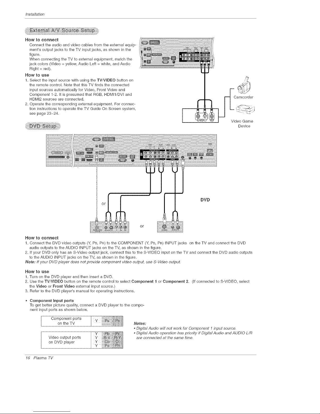
How to COnnect
Connect the audio and video cables from the external equip-
ment's output jacks to the TV input jacks, as shown in the
figure=
When connecting the TV to external equipment, match the
jack colors (Video = yellow, Audio Left = white, and Audio
Right = red).
How to use
1. Select the input source with using the TV/VIDEO button on
the remote control. Note that this TV finds the connected
input sources automatically for Video, Front Video and
Component 1-2. It is presumed that RGB, HDMI!/DVI and
HDMI2 sources are connected.
2. Operate the corresponding external equipment. For connec-
tion instructions to operate the TV Guide On Screen system,
see page 23~24.
Camcorder
Video Game
Device
DVD
or
How to connect
1. Connect the DVD video outputs (Y, PB, PR) to the COMPONENT (Y, PB, PR) INPUT jacks on the TV and connect the DVD
audio outputs to the AUDIO INPUT iacks on the TV, as shown in the figure.
2. If your DVD only has an S-Video output jack, connect this to the S-VIDEO input on the TV and connect the DVD audio outputs
to the AUDIO INPUT jacks on the TV, as shown in the figure.
Note: If your DVD player does not provide component video output, use S-Video outpuL
_OW tO USe
1. Turn on the DVD player and then insert a DVD.
2. Use the TV/VmDEO button on the remote control to select Component 1 or Component 2. (if connected to S-VIDEO, select
the Video or Front Video external input source.)
3. Refer to the DVD player's manual for operating instructions.
Component Input ports
To get better picture quality, connect a DVD player to the compo-
nent input ports as shown below.
Component ports
on the TV
Video output ports
on DVD player
Y ii!!!!!!!i
v
Y
Notes:
• Digital Audio will not work for Component 1input source.
. Digital Audio operation has priority if Digital Audio and AUDIO L/R
are connected at the same time.
16 Plasma TV
Installation
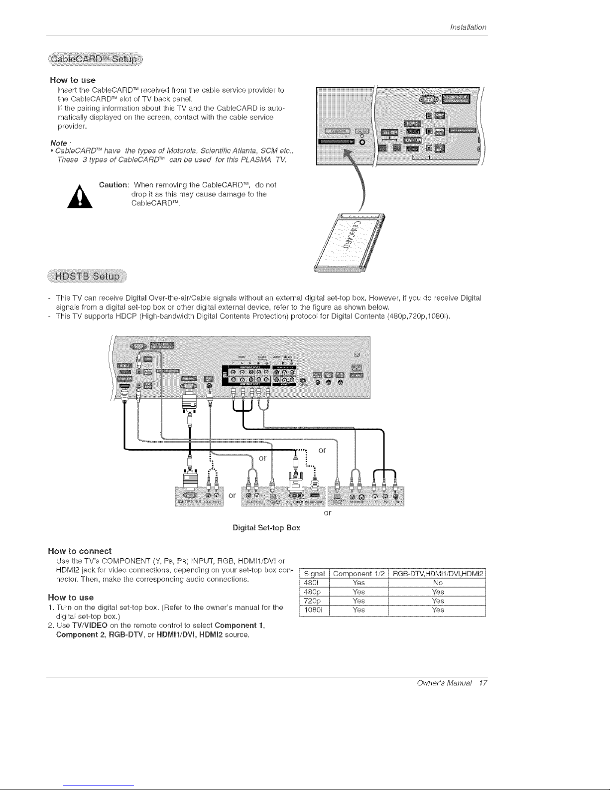
How to use
Insert the CableCARD TM received from the cable service provider to
the CableCARD TM slot of TV back panel.
If the pairing information about this TV and the CabieCARD is auto-
matica!ly displayed on the screen, contact with the cable service
provider.
Note :
, CableCARD TM have the types of Motorola, Scientific Atlanta, SCM etc..
These 3 types of CableCARD TM can be used for this PLASMA TV.
Caution: When removing the CableCARD TM, do not
drop it as this may cause damage to the
CableCAR DTM.
- This TV can receive Digital Over-the-air/Cable signals without an external digital set-top box. However, if you do receive Digital
signals from a digital set-top box or other digital external device, refer to the figure as shown below.
- This TV supports HDCP (High-bandwidth Digital Contents Protection) protocol for Digital Contents (480p,720p,1080i).
or
Digita_ Set-top Box
How to connect
Use the TV's COMPONENT (Y, PB, PR) INPUT, RGB, HDMWDVI or
HDMI2 jack for video connections, depending on your set-top box con-
nector= Then, make the corresponding audio connections.
How to use
1. Turn on the digital set-top box. (Refer to the owner's manual for the
digital set-top box.)
2. Use TV/WDEO on the remote control to select Component 1,
Component 2, RGB-DTV, or HDMN/DVL HDMm2 source.
or
Signal Component 1/2 RGB-DTV, HDMI!/DVI,HDMI2
480i Yes No
480p Yes Yes
720p Yes Yes
1080i Yes Yes
Owner_Manual 17

Installation
- This TV provides Plug and Play capability, meaning that the PC adiusts automatically to the TV's settings.
- The TV perceives 840x480, 80Hz as DTV 480p based on the PC graphic card, change the screen scanning rate for the graphic
card accordingly=
<When the PC supports DVS>
HOW to Connect
1. Connect the PC to HDMtl/DVI port of this TV with an HDMI-to-DVI cable(not supplied with this product).
If you do not need to connect audio, HDMI2 port is also available for the DVl video connection.
2. If the PC(or the sound card of the PC) has a fiber optic digital audio output connector, connect the PC's audio output to DlGI-
TAL AUDIO(OPTICAL) port for DVl INPUT.
3. If the PC(or the sound card of the PC) has an analog audio output connector, connect the PC's audio output to AUDIO INPUT
port located on the right side of RGB INPUT port.
How To Use
1. To get the best picture quality, adjust the PC graphics card to 1024x788, 60Hz=
2. Select HDMI!/DVl input source in main input option of SETUP menu.(Refer to R84)
TV/VmDEO button is also available for this purpose.
3. Check the image on your TV. There may be noise associated with the resolution, vertical pattern, contrast or brightness in PC
mode. If noise is present, change the PC output to another resolution, change the refresh rate to another rate or adiust the
brightness and contrast on the VIDEO menu until the picture is clear. If the refresh rate of the PC graphic card can not be
changed, change the PC graphic card or consult the manufacturer of the PC graphic card.
<When the PC supports RGB>
HOW to connect
1. Connect the PC to RGB INPUT port of this TV with a RGB cable(not supplied with this product).
2. If the PC(or the sound card of the PC) has an analog audio output connector, connect the PC's audio output to AUDIO INPUT
port located on the right side of RGB INPUT port.
How To Use
1. To get the best picture quality, adiust the PC graphics card to 1024x788, 80 Hz.
2=Select RGB_PC input source in main input option of SETUP menu=(Refer to R84)
Once you select RGB-PC in main input option of SETUP menu, TV/WDEO button is also available for this purpose.
3=Check the image on your TV=There may be noise associated with the resolution, vertical pattern, contrast or brightness in PC
mode. if noise is present, change the PC output to another resolution, change the refresh rate to another rate or adjust the
brightness and contrast on the VIDEO menu until the picture is clear. If the refresh rate of the PC graphic card can not be
changed, change the PC graphic card or consult the manufacturer of the PC graphic card.
Monitor Dispmay Specifications (RGB-PC)
Resolution
720x400
840x480
Horizontam
Frequency(KHz)
31=489
37.927
31=489
37=881
37=500
43=269
Vertiea_
Frequeney(Hz)
70,08
85=03
89=94
72,80
75=00
85=00
Resolution
800x600
1024x788
18 P_sma TV
Horizonta_
Frequeney(KHz)
38=158
37.879
48.077
48=875
83=674
48=363
88=478
80=023
Vertieam
Frequeney(Hz)
58=25
80=3!
72.18
75=00
85.06
60=00
70=06
75=02
lns_llation
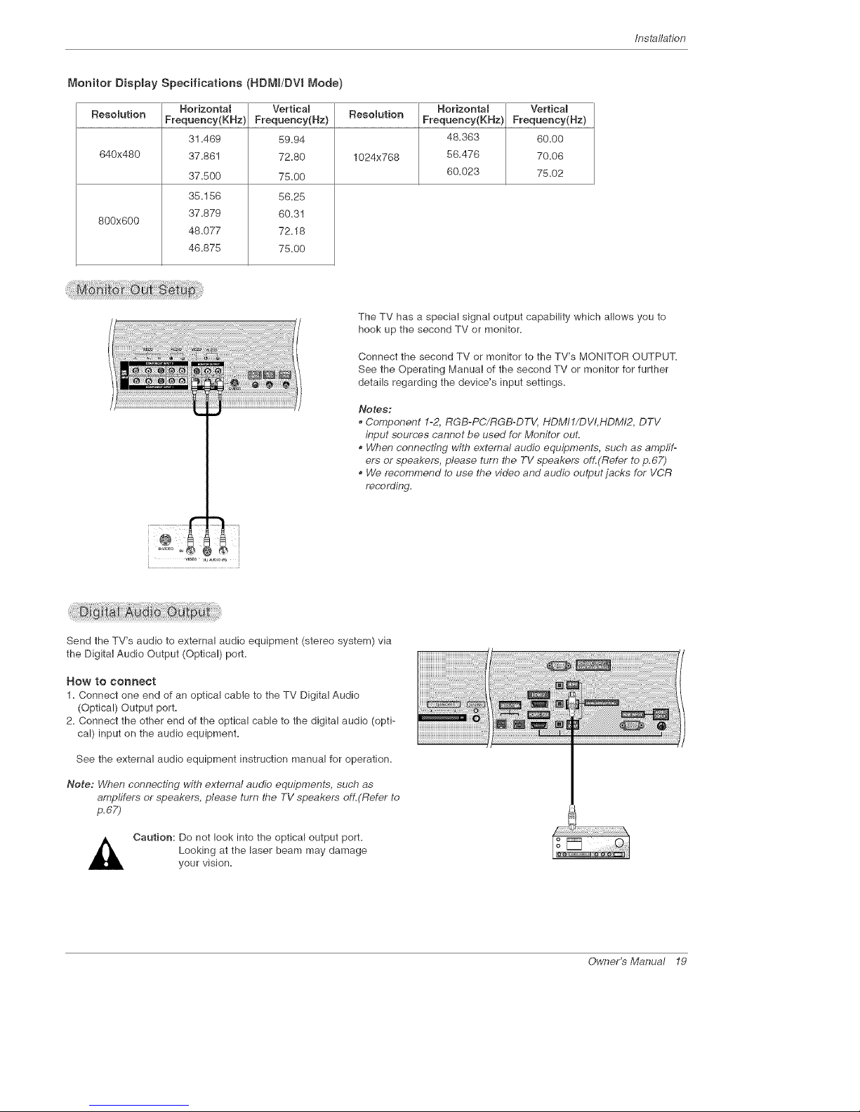
Monitor Dispmay Specifications (HDMI/DV8 Mode)
Horizonta_ Vertica_ Horizonta_ Vertica_
Resolution Frequency(KHz) Frequency(Hz) Resolution Frequency(KHz) Frequency(Hz)
31.489 89.94 48.363 80.00
840x480 37.881 72.80 1024x768 88.478 70.08
37.500 78.00 80.023 75.02
35.158 5825
37.879 80.31
800x800
48.077 72.18
48.878 75.00
The TV has a special signal output capability which allows you to
hook up the second TV or monitor.
Connect the second TV or monitor to the TV's MONITOR OUTPUT.
See the Operating Manual of the second TV or monitor for further
details regarding the device's input settings.
Notes:
• Component 1-2, RGB-PC/RGB-DTV, HDMI1/DVI, HDMI2, DTV
input sources cannot be used for Monitor out.
, When connecting with external audio equipments, such as amplff-
ors or speakers, please turn the TV speakers off.(Refer to p.67)
, We recommend to use the video and audio output jacks for VCR
recording,
Send the TV's audio to external audio equipment (stereo system) via
the Digital Audio Output (Optical) port.
How to connect
1=Connect one end of an optical cable to the TV Digital Audio
(Optical) Output port=
2= Connect the other end of the optical cable to the digital audio (opti-
cal) input on the audio equipment=
See the external audio equipment instruction manual for operation.
Note: When connecting with external audio equipments, such as
ampfifers or speakers, please turn the TV speakers off.(Refer to
p,67)
Caution: Do not look into the optical output port.
Looking at the laser beam may damage
your vision.
Owner_Manual 19
lnstaflation
HIGH DEFINITION MULTIMEDIA INTERFACE
- HDMI TM, the HDMI logo and High-Definition Multimedia Interface is a trademark or registered trademark of HDMI Licensing.
- This TV can receive the High-Definition Multimedia Interface(HDMI) or the Digital Visual h7terface(DVI).
- This TV supports HDCP(High-bandwidth Digital Contents Protection) Protocol for 720x480p, 1280x720p, and 1920x!0801 resolu-
tion.
- When you connect this TV with a source device(DVD player, Set Top Box or PC) supporting Auto HDMI/DVl function, the output
resolution of the source device will be automatically set to 1280x720p.
- If the source device does not support Auto HDMI/DVl, you need to set the output resolution appropriately.
To get the best picture qualify, adjust the DVD Player or Set Top Box's output resolution to 1280x720p, and the PC graphics card's
output resolution to !024x768, 60Hz.
- If the source device has an HDMI output, no other audio connection is necessary because HDMI-to-HDMI connection includes
both video and audio.
- If the source device has a DVI output and no HDMI output, a separated audio connection is necessary.
<When the source device(DVD player or Set Top Box) supports HDMI>
How To Connect
1. Connect the source device to HDMI!/DVI or HDMI2 port of this TV with an HDMI cable(not supplied with this product).
2. No separated audio connection is necessary.
How To Use
- If the source device supports Auto HDMI function, the output resolution of the source device will be automatically set to 1280x720p.
- If the source device does not support Auto HDMI, you need to set the output resolution appropriately.
To get the best picture quality, adiust the output resolution of the source device to 1280x720p.
- Select HDMI!/DVI or HDMI2 input source in main input option on the SETUP menu.(Refer to R64)
TV/WDEO button is also available for this purpose.
<When the source device(DVD player or Set Top Box) supports DVI>
How To Connect
1. Connect the source device to HDMI!/DVI port of this TV with a HDMI-to-DVI cable(not supplied with this product).
Do not use HDMI2 port for DVI connection if you want to connect audio.
2. A separated audio connection is necessary.
3. If the source device has a fiber optic digital audio output, connect the audio output to DIGITAL AUDIO(OPTICAL) port for DVl
iNPUT.
4. Connect the PC's audio output to AUDIO INPUT port located on the right side of RGB INPUT port.
How To Use
- If the source device supports Auto DVl function, the output resolution of the source device will be automatically set to 1280x720p.
- If the source device does not support Auto DVI, you need to set the output resolution appropriately.
To get the best picture quality, adjust the output resolution of the source device to 1280x720p.
- Select HDMI1/DVl input source in main input option on the SETUP menu.(Refer to R64)
TV/WDEO button is also available for this purpose.
20 P_sma TV
Installation
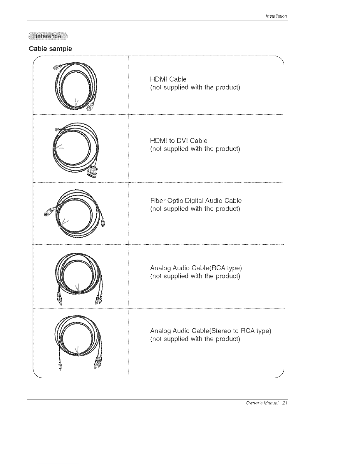
Cable sample
f
X
Owner's Manual 21
HDM[ CaMe
(not supplied with the product)
C HDM[ to DV[ CaMe
Y (not supplied with the product)
Fiber Optic Digital Audio CaMe
(not supplied with the product)
Analog Audio Cab[e(RCA type)
(not supplied with the product)
Analog Audio CaMe(Stereo to RCA type)
(not supplied with the product)

Installation
_OW to use
1=Connect the HDMI1/DVI Source Devices(DVD Player or Set Top Box or PC) and the TV SET=
2. Turn on the display by pressing the POWER button on the TV SET and HDMI1/DVl Source Devices remote control.
3. Select HDMtl/DVl Input source in Main Input option on the SETUP menu.(Refer to R84)
4. Check the image on your TV SET= There may be noise associated with the resolution, vertical pattern, contrast or brightness in
HDMI!/DVl Source Devices. If noise is present, change the HDMI1/DVl Source Devices to another resolution, change the
refresh rate or adjust the brightness and contrast on the menu until the picture is clear. If the refresh rate of the PC graphics
card can not changed, change the PC graphics card or consult the manufacturer of the PC graphics card.
Notes:
- Depending on the graphics card, DOS mode may not work if a HDMI to DVI Cable is in use.
- Avoid keeping a fixed image on the screen for a long period of time. The fixed image may become permanently imprinted on the
screen. Use the Orbiter feature on the ISM Method menu.
- When Soume Devices connected with HDM!I/DW Input, output PC Resolution(VGA, SVGA, XGA), Position and Size may not fit
to Screen. As shown the picture below, press the ADJUST button to adjust the screen Position of TV SET and contact an PC
graphics card service centei:
- When Soume Devices connected with HDMI1/DVI Input, output TV SET Resolution(480p, 720p, 1080i) and TV SET Display fit
EIAJCEA-861-B Specification to Screen. If not, refer to the Manual of HDMI1/DVI Source Devices or contact your service cen-
ter:
- In case HDMI1/DW Soume Devices is not connected Cable or poor cable connection, "NO SIGNAL" OSD display in HDMI1/DW
lnpuL In case that Video Resolution is not supported TV SET output in HDMI1/DW Soume Devices, "INVALID FORMAT" OSD
display. Refer to the Manual of HDMI1/DW Soume Devices or contact your service center.
PC mode
in This Mode, the Supported TV SET Resolution Specification
- 1920x 1080 I @ 59=94Hz / 80Hz, 16:9
- 1280 x 720 P @ 59=94Hz / 60Hz, 16:9(preferred format)
- 720 x 480 P @ 59=94Hz / 6OHz, 16:9
- 720 x 480 P @ 59=94Hz / 80Hz, 4:3
_nThis Mode, the Supported PC Resolution Specification
- 840 x 480 @ 80Hz
- 840 x 480 @ 72Hz
- 840 x 480 @ 75Hz
- 800 x 600 @ 88Hz
- 800 x 600 @ 8OHz
- 800 x 600 @ 72Hz
- 800 x 890 @ 75Hz
- 1024 x 788 @ 80Hz(preferred format)
- 1024 x 788 @ 70Hz
- 1024 x 788 @ 75Hz
22 Plasma TV

Installation
- The TV Guide On Screen system uses Setup information to provide you with show listings and lineups in your area--which are
updated several times a day.
- Once you set up the TV according to manufacturer's instructions, you are ready to set up the TV Guide On Screen system.
- To download program listings the TV Guide On Screen system needs to be able to change channels on your cable box when
the TV is not in use. Please connect the supplied G-LINK cable to the G-LINK jack of the TV. After rou connect the G-LINK
cable you will be able to control your cable box using the TV's remote.
Notes:
• The TV Guide On Screen system provides listings for cable-ready, cable box, and digital cable services as well as over-the-air
broadcast. It does not provide listings for satellite services.
You may use to connect directly without Cable Box.
How to connect VCR and Cable Box
VCR Rear
VCR Front
VCR Rear
Owner's Manual 23

/nstallat/on
VCR Front
Cable Box Front
I I
_____d
o_ , _@ ¢3 @ I VCR Rear
CabUe Rex Rear
VCR Front
nn a _i _ i 61
VCR Front
CabUe Re× Front
I _ + I
24 Plasma TV
Installation
Note:
•TheG-L/Nf<r_"cable is necessary for the TV Guide On Screen system to work with your Cab/e Box and VCR. See Page
23-24 for G-LINK TMconnection instructions.
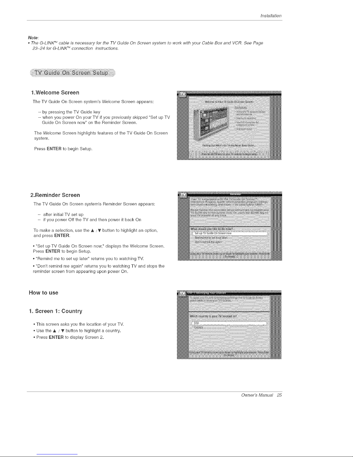
1.Welcome Screen
The TV Guide On Screen system's Welcome Screen appears:
-- by pressing the TV Guide key
-- when you power On your TV if you previously skipped "Set up TV
Guide On Screen now" on the Reminder Screen,
The Welcome Screen highlights features of the TV Guide On Screen
system,
Press ENTER to begin Setup,
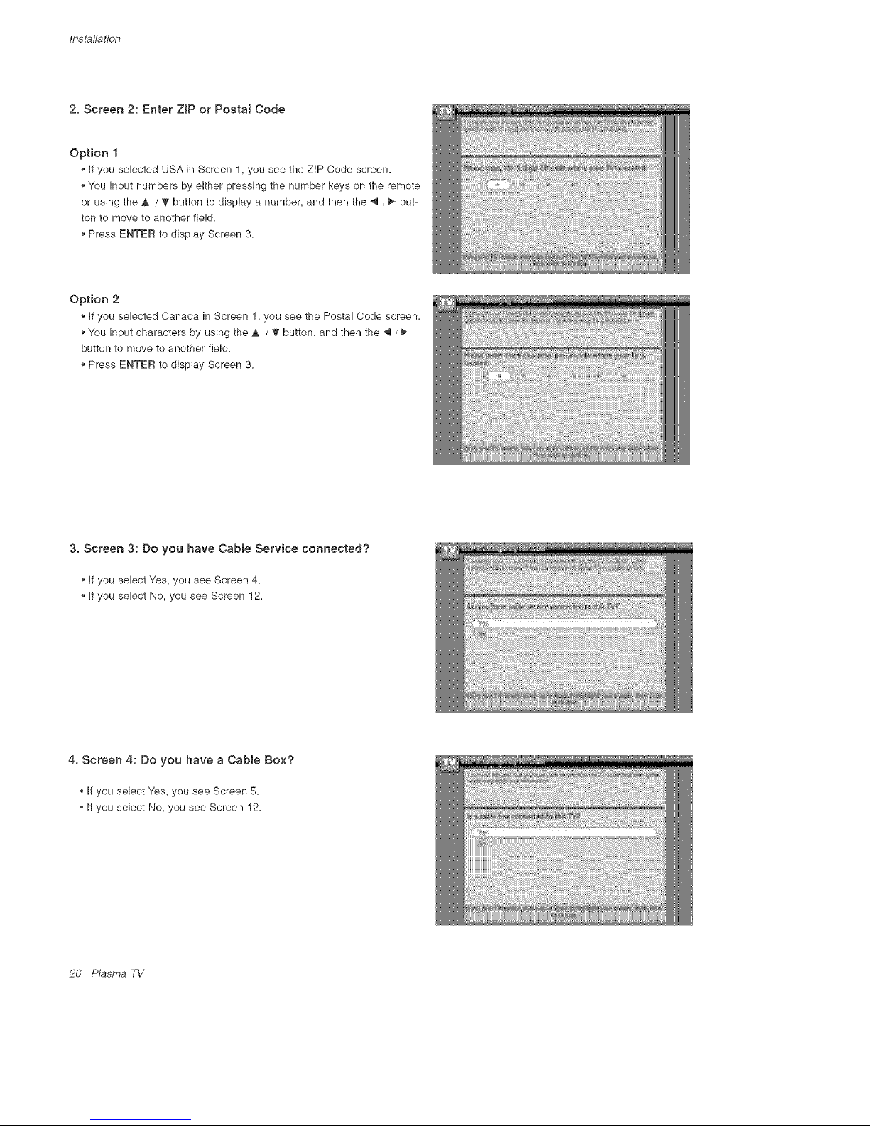
2.Reminder Screen
The TV Guide On Screen system's Reminder Screen appears:
-- after initial TV set up
-- if you power Off the TV and then power it back On
To make a selection, use the A / _' button to highlight an option,
and press ENTER,
• "Set up TV Guide On Screen now," displays the Welcome Screen,
Press ENTER to begin Setup,
• "Remind me to set up later" returns you to watching TV,
"Don't remind me again" returns you to watching TV and stops the
reminder screen from appearing upon power On,
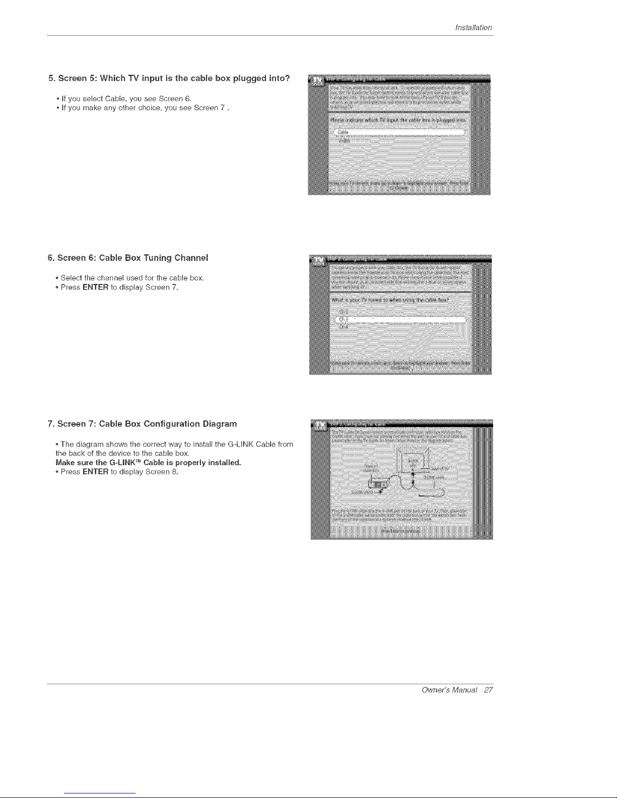
How to use
1. Screen 1: Country
This screen asks you the location of your TV,
Use the A / _" button to highlight a country,
Press ENTER to display Screen 2,
Owner_Manual 25
Installation
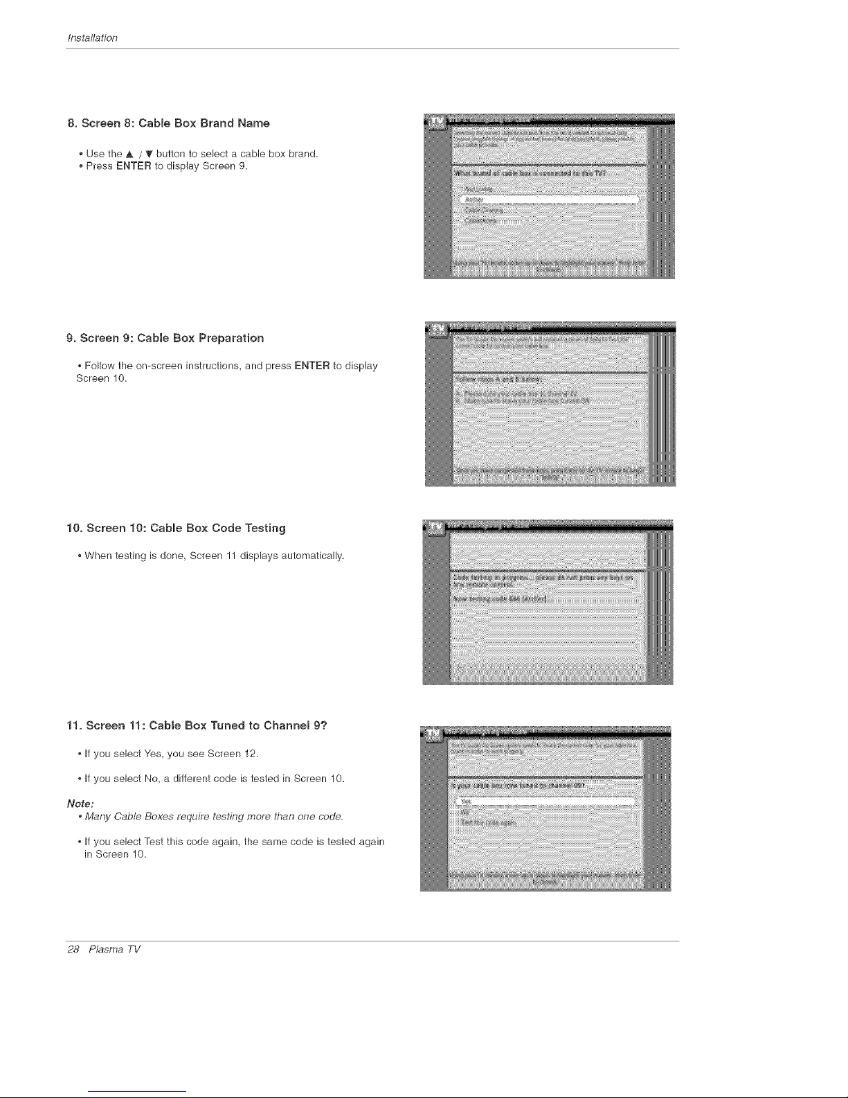
2. Screen 2: Enter ZiP or Postam Code
Option 1
• If you selected USA in Screen 1, you see the ZiP Code screen.
• You input numbers by either pressing the number keys on the remote
or using the A / _" button to display a number, and then the _ / _ but-
ton to move to another field.
Press ENTER to display Screen 3.
Option 2
*,If you selected Canada in Screen 1, you see the Postal Code screen.
*,You input characters by using the ,& / _ button, and then the 4 /
button to move to another field.
. Press ENTER to display Screen 3.
3. Screen 3: Do you have Cabme Service connected?
• if you select Yes, you see Screen 4.
•, If you select No, you see Screen 12.
4. Screen 4: Do you have a Cabte Box?
,, If you select Yes, you see Screen 5.
,, If you select No, you see Screen 12.
26 P_sma TV
Installation
5. Screen 5: Which TV input is the cabme box pmugged into?
, if you select Cable, you see Screen 6=
, If you make any other choice, you see Screen 7 =
6. Screen 6: CaNe Box Tuning Channel
Select the channel used for the cable box=
Press ENTER to display Screen 7=
7. Screen 7: Cabte Box Configuration Diagram
The diagram shows the correct way to install the G-LINK Cable from
the back of the device to the cable box=
Make sure the G-LmNKTM Cable is property installed.
* Press ENTER to display Screen 8=
Owner's Manual 27
Installation
8. Screen 8: Cabme Box Brand Name
• Use the _. / '_" button to select a cable box brand.
• Press ENTER to display Screen 9=
9. Screen 9: CaNe Box Preparation
Follow the on-screen instructions, and press ENTER to display
Screen 10=
10. Screen 10: Cabme Box Code Testing
When testing is done, Screen 11 displays automatically=
11. Screen 11: Cable Box Tuned to Channel 9?
If you select Yes, you see Screen 12=
If you select No, a different code is tested in Screen 10=
No_e:
• Many Cable Boxes require testing more than one code.
If you select Test this code again, the same code is tested again
in Screen 10=
28 P_sma TV

Installation
12. Screen 12: Do you have an antenna connected?
If you select Yes, you see Screen 13=
Note:
, If you selected No in Screen 3 then you must
select Yes in this screen to receive a channel
lineup and listings.
• If you select No, you see Screen 13=
13. Screen 13: Are your basic settings correct?
If you select Yes, you see Screen 14=
, If you select No, you see Screen 1=
14. Screen 14: Congratulations
Press ENTER to display Screen 15=
Owner_Manual 29
Installation
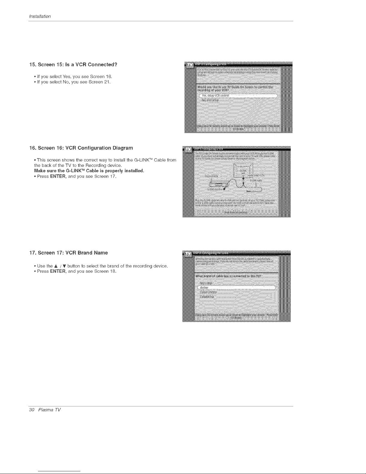
15. Screen 15: ts a VC£ Connected?
If you select Yes, you see Screen 16.
• If you select No, you see Screen 21.
l& Screen 16: VC£ Configuration Diagram
This screen shows the correct way to install the G-LINK rMCable from
the back of the TV to the Recording device.
Make sure the G_UNK TMCable is property instaHe&
• Press ENTER, and you see Screen 17.
17. Screen 17: VCR Brand Name
• Use the _, / ? button to select the brand of the recording device,
• Press ENTER, and you see Screen 18,
30 P_sma TV
 Loading...