

LG 42"" PDP SVC, MN-42PZ10 Training Manual

42
42 42
42 Inch(Wide)
Inch(Wide)Inch(Wide)
Inch(Wide) PDP SVC Training Manual
PDP SVC Training Manual PDP SVC Training Manual
PDP SVC Training Manual
LG Electronics / DND QA
Contents
ContentsContents
Contents
Ⅰ
ⅠⅠ
Ⅰ. Usage/Service Points to be concerned
Ⅱ
ⅡⅡ
Ⅱ. Module formation & spec
Ⅲ
ⅢⅢ
Ⅲ. Screen defect diagnosis
1. 4/7 or 3/7 of screen is not displayed.
2. Screen by Data COF is not displayed.
3. one or more of Data COF IC have regular vertical lines.
4. Data COF IC unit error pattern
5. The screen by Scan COF is not displayed.
6. Regular- interval vertical line in the whole screen.
7. Vertical data copy
8. One or more vertical bars.
9. One or more horizontal bars.
10. Input signal pattern is displayed but the whole brightness of screen is dark.
11. In full white pattern, foreign color is displayed or in full black pattern, misdischarge is partially occurred..
12. In full white pattern, the brightness is getting darker toward the center.
13. A specific brightness of one color is not clear.
Ⅳ
ⅣⅣ
Ⅳ. Non-picture defect diagnosis
!
!!
!. One Point Service Guide(42 Inch, 40 Inch)
LG Electronics/DND QA
LG Electronics/DND QA LG Electronics/DND QA
LG Electronics/DND QA Gr
GrGr
Gr
ⅠⅠⅠⅠ.
. .
. Usage/Service points to be concerned
Usage/Service points to be concernedUsage/Service points to be concerned
Usage/Service points to be concerned
SUGGGESTIONS
1. Static precaution
Drive section circuit is C-MOS circuit, so to protect against static electricity, wear static-proof wrist band.
2. Cleaning
when wiping panel, do not use liquid cleaner or other chemicals . Use a damp cloth for cleaning .
3. handling
Color PDP uses high voltage(Max.500V). Be aware of electronic shock when handling PDP Unit and don’t touch drive circuit.
and even driver circuit’s capacitor is turned off but charge still remains there, so to touch drive circuit, be sure to wait at least 1 minute.
4. Warning when connecting signal & Power Connector in operation
do not touch connector while Color PDP is operating.
5. PDP servicing and guarantee
Glass Panel and Drive Circuit section are linked and operating together.
if you disassemble and assemble the product in your own hands , LGE is exempted from the guarantee of function, quality and etc.
6. Damage in still image
Color PDP uses fluorescent material. The quality of PDP fluorescence by nature becomes deteriorated if using it in the same condition of CRT.
To prevent this symptom, input full-screen regularly or use screensaver software.
So do not display the still image for a long time.
7. Temperature & ventilation
Color PDP’s Glass Panel section and Drive circuit section emit the heat so the temperature shall be kept under 40.
the temperature of glass panel section is pretty high because built-in drive circuit emits the heat.
PDP is operating with high voltage therefore be sure to keep it away from conductive objects.
8. Warning when handling Module
be aware that PDP shall not be touched by metal or hard objects and shocked by the heat or mechanical force.
be careful when disassembling or handling.
be sure to wear glove for preventing injury when the glass’s broken.
Color PDP is a display device consisting of Panel section & Drive section. Panel section is composed of electrode,
fluorescent substances ,dielectrics and gases, and drive section is a combination of electrical circuit section and
PCB section. We call this concrete as PDP Module Ass’y and the following shows warning.
LG Electronics/DND QA
LG Electronics/DND QA LG Electronics/DND QA
LG Electronics/DND QA Gr
GrGr
Gr
Service warning
1. One DVM ( FLUKE 87 or similar type )
2. Digital Oscilloscope ( over 200MHZ )
Defect diagnosis tool
1. When inserting parts or PCB, fasten the lead line to terminal before soldering.
2. When inserting high- voltage resistance(metal oxide film resistance or metal film resistance), keep 10mm away from PCB
3. High-voltage or high-temperature parts shall be away from the lead line.
4. This chassis is insulation(cold) chassis but for safety, it is better to use insulation trance.
when servicing power board, be sure to use insulation trance.
5. While PDP Module is in operatio n, d o not connect or remove lines.
"
""
" With COF or panel defect, report it to LGE PDP module service department.
LG Electronics/DND QA
LG Electronics/DND QA LG Electronics/DND QA
LG Electronics/DND QA Gr
GrGr
Gr
Power : 220V 60Hz
Power : 220V 60HzPower : 220V 60Hz
Power : 220V 60Hz
Power consumption : 340W
Power consumption : 340WPower consumption : 340W
Power consumption : 340W
#056
#056#056
#056
#259
#259#259
#259
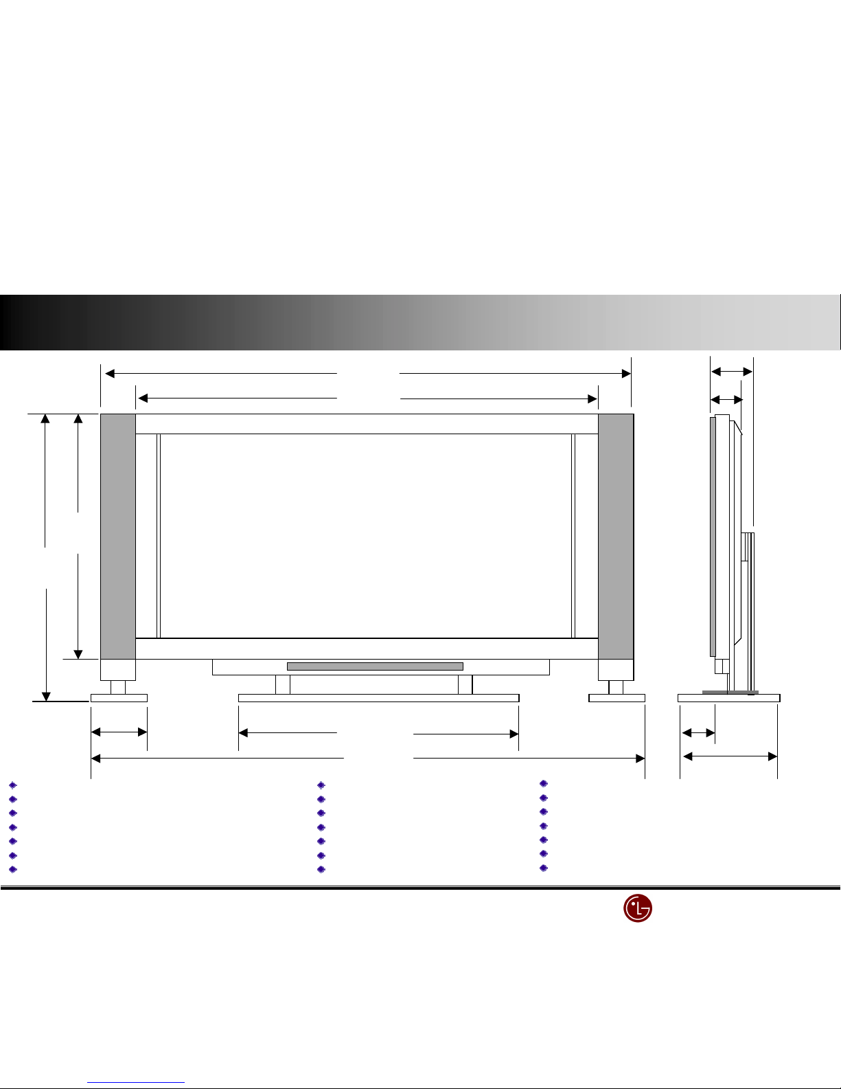
635
635635
635
693.5
693.5693.5
693.5
220
220220
220
779.5
779.5779.5
779.5
#379
#379#379
#379
##4.8
##4.8##4.8
##4.8
28#
28#28#
28#
82
8282
82
9#.5
9#.59#.5
9#.5
aspect ratio: #6:9
aspect ratio: #6:9 aspect ratio: #6:9
aspect ratio: #6:9
screen size (H X V) : 920.# X 5#8.4mm
screen size (H X V) : 920.# X 5#8.4mmscreen size (H X V) : 920.# X 5#8.4mm
screen size (H X V) : 920.# X 5#8.4mm
resolution : 852 X 480 (VGA)
resolution : 852 X 480 (VGA)resolution : 852 X 480 (VGA)
resolution : 852 X 480 (VGA)
Cell Pitch (H X V) : 0.36 X #.08
Cell Pitch (H X V) : 0.36 X #.08Cell Pitch (H X V) : 0.36 X #.08
Cell Pitch (H X V) : 0.36 X #.08
displayable colors (R,G,B) : #,677K (256 X 256 X 256)
displayable colors (R,G,B) : #,677K (256 X 256 X 256)displayable colors (R,G,B) : #,677K (256 X 256 X 256)
displayable colors (R,G,B) : #,677K (256 X 256 X 256)
brightness : 250
brightness : 250 brightness : 250
brightness : 250 cd
cdcd
cd////$$$$ (w/o filter : 550
(w/o filter : 550 (w/o filter : 550
(w/o filter : 550 cd
cdcd
cd////$$$$ ))))
contrast ratio : 250:# (w/o filter ; 700:# )
contrast ratio : 250:# (w/o filter ; 700:# )contrast ratio : 250:# (w/o filter ; 700:# )
contrast ratio : 250:# (w/o filter ; 700:# )
color temperature : over 8500
color temperature : over 8500color temperature : over 8500
color temperature : over 8500%%%% K
K K
K
viewing angle : over #60
viewing angle : over #60viewing angle : over #60
viewing angle : over #60%%%%
input signal : NTSC, HD, VGA ,SVGA
input signal : NTSC, HD, VGA ,SVGAinput signal : NTSC, HD, VGA ,SVGA
input signal : NTSC, HD, VGA ,SVGA
Twin Picture : PC/AV
Twin Picture : PC/AVTwin Picture : PC/AV
Twin Picture : PC/AV
PC input : D
PC input : DPC input : D
PC input : D----SUB #5
SUB #5SUB #5
SUB #5
Control : D
Control : DControl : D
Control : D----SUB25 / STB connection
SUB25 / STB connectionSUB25 / STB connection
SUB25 / STB connection
Video input : CVBS
Video input : CVBSVideo input : CVBS
Video input : CVBS
SSSS----Video input
Video inputVideo input
Video input
DVD input(Y,
DVD input(Y,DVD input(Y,
DVD input(Y,Cb
CbCb
Cb,Cr)/R,L : Y/Y.
,Cr)/R,L : Y/Y. ,Cr)/R,L : Y/Y.
,Cr)/R,L : Y/Y. Pb
PbPb
Pb////Cb
CbCb
Cb, Pr/Cr+R/L
, Pr/Cr+R/L, Pr/Cr+R/L
, Pr/Cr+R/L
Audio input : R/L
Audio input : R/LAudio input : R/L
Audio input : R/L
Power Cable : 3
Power Cable : 3Power Cable : 3
Power Cable : 3&&&& ((((Ground terminal)
Ground terminal)Ground terminal)
Ground terminal)
Sound Output (Speaker) : R.L Out
Sound Output (Speaker) : R.L OutSound Output (Speaker) : R.L Out
Sound Output (Speaker) : R.L Out
R,G,B input : D
R,G,B input : DR,G,B input : D
R,G,B input : D----SUB25 (RGBHV) : STB connection
SUB25 (RGBHV) : STB connectionSUB25 (RGBHV) : STB connection
SUB25 (RGBHV) : STB connection
AC Input : 220V 60Hz
AC Input : 220V 60HzAC Input : 220V 60Hz
AC Input : 220V 60Hz
MN
MNMN
MN----42PZ10 Spec & Features
42PZ10 Spec & Features42PZ10 Spec & Features
42PZ10 Spec & Features
LG Electronics/DND QA
LG Electronics/DND QA LG Electronics/DND QA
LG Electronics/DND QA Gr
GrGr
Gr
ITEMS SPECIFICATIONS(Tentative)
Screen Size: 42 inch/ 106cm diagonal
Aspect Ratio: 16 :9 (width:height)
Resolution: 852 x 480 Pixels(SD grade)
Peak Brightness : typ.240cd/m² (with filter 60%)
Contrast Ratio: 700:1(Dark Room & with filter 45%)
Viewing Angle: 160° horizontally and vertically
Displayable Colors: 16.7 million
Weight: kg (MNT), kg(D/stand), kg(spk.)x2
Life: >25,000 hours
(elapsed time to 50% of initial brightness)
Dimensions(MNT) : 105.6cm wide, 63.4cm high, 8.2cm deep
Input Terminals : RF terminal(PAL/SECAM/NTSC)
(Set Top Box) Composite Video input(RCA) X 2, S-Video
Audio L&R input(RCA) X 2
Component Video (Y,Pb,Pr) + R/L for DVD
Component Video (Y,Pb,Pr)+ R/L for HDTV Stb.
RGB-SUB 15 pin for HDTV Stb.(480p/720p/1080i)
Analog RGB-SUB 15pin(PC VGA ~SVGA)
Stereo Input for PC Audio
Output Terminals : Analog RGB-SUB 15 pin(PC/DTV input bypass)
(Set Top Box) Audio L&R(RCA)
RGB-SUB 25 Pin for MNT(RGB/HV in & Control)
Composite Video output + R/L output
Input Terminals : Analog RGB-SUB 15 pin (Compatible with PC
(MNT) VGA ~SVGA, Compressed XGA)
RGB-SUB 25 Pin for STB(RGB/HV in & Control)
Component Video (Y,Pb,Pr) for DVD & DTV Stb.
Composite Video input(PAL/SECAM/NTSC)
Audio L&R input(RCA)X2
Display Frequency : 15.73kHz to 60kHz horizontally, 50Hz to 75Hz(V)
Picture : PIP(2Tuner:STB), Twin Picture, Digital Comb filter,
Digital Video Enhancer(Jagging free )
Sound : A2 stereo, AVL, Dolby Virtual, 2x10Wrms
Remote Control : Included(Unified)
External Control : D-sub 25-pin connector
Power Source : 110-240V , 50/60 Hz
Power Consumption: 300 watts( with Max. Audio : 320W)
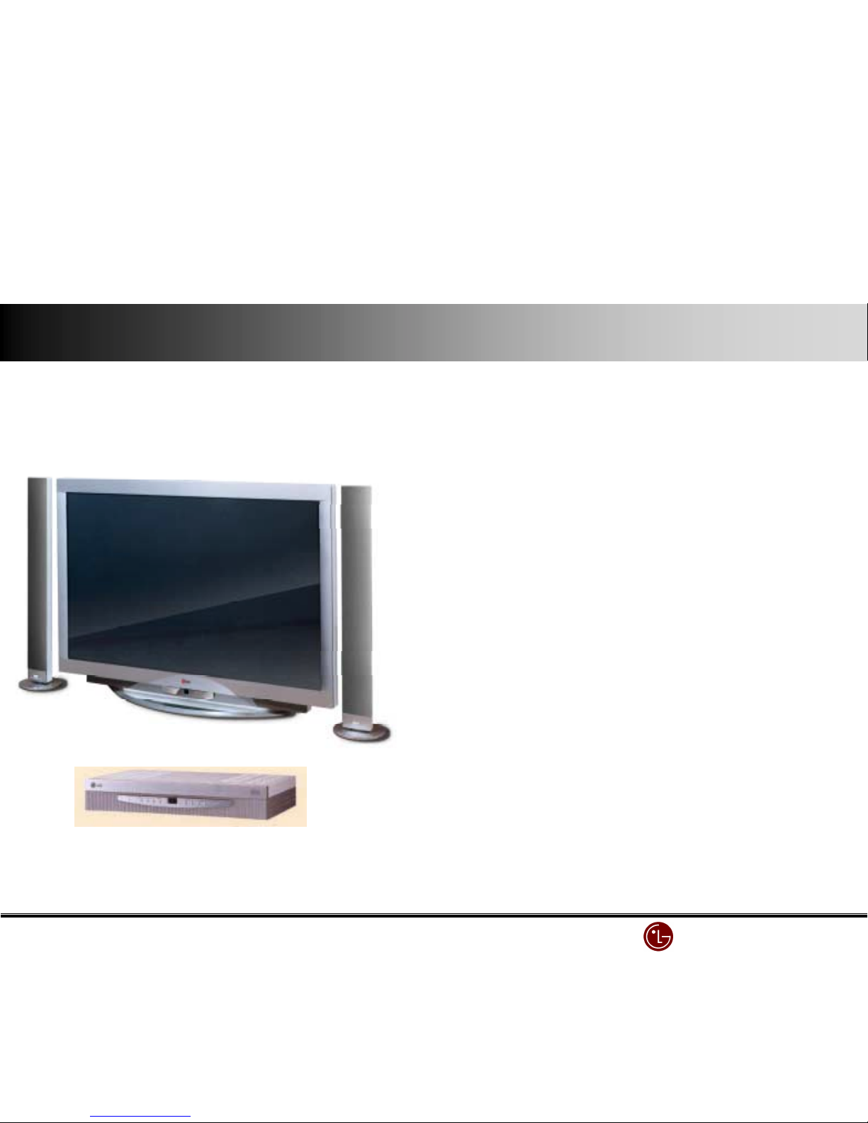
MN-42PZ10(42”W PDP MNT)
Market : Korea / N_ America / S_America
Market : Korea / N_ America / S_AmericaMarket : Korea / N_ America / S_America
Market : Korea / N_ America / S_America
(200#. July ~)
(200#. July ~)(200#. July ~)
(200#. July ~)
Spec of Models
Spec of ModelsSpec of Models
Spec of Models
RN
RNRN
RN----BA##(3 System Multi STB)
BA##(3 System Multi STB)BA##(3 System Multi STB)
BA##(3 System Multi STB)
430(W)X78(H)X280mm(D)
((((Example of Desk Top Type)
Example of Desk Top Type)Example of Desk Top Type)
Example of Desk Top Type)
LG Electronics/DND QA
LG Electronics/DND QA LG Electronics/DND QA
LG Electronics/DND QA Gr
GrGr
Gr
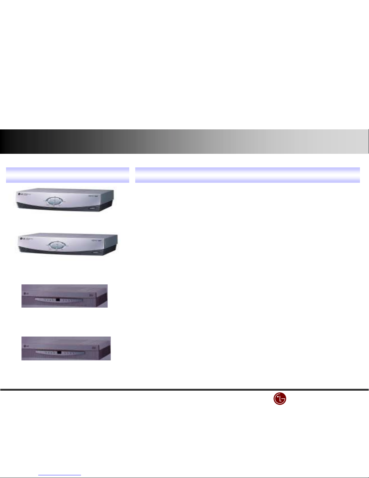
DIGITAL SET TOP BOX ( SK
DIGITAL SET TOP BOX ( SKDIGITAL SET TOP BOX ( SK
DIGITAL SET TOP BOX ( SK----0##T )
0##T )0##T )
0##T )
DIGITAL SET TOP BOX ( SK
DIGITAL SET TOP BOX ( SKDIGITAL SET TOP BOX ( SK
DIGITAL SET TOP BOX ( SK----0#0T )
0#0T )0#0T )
0#0T )
ANALOG SET TOP BOX ( RN
ANALOG SET TOP BOX ( RNANALOG SET TOP BOX ( RN
ANALOG SET TOP BOX ( RN----BA#0 )
BA#0 )BA#0 )
BA#0 )
ANALOG SET TOP BOX ( RN
ANALOG SET TOP BOX ( RNANALOG SET TOP BOX ( RN
ANALOG SET TOP BOX ( RN----BA## )
BA## )BA## )
BA## )
MN
MNMN
MN----40PA#0, MN
40PA#0, MN40PA#0, MN
40PA#0, MN----40PA#0A only
40PA#0A only40PA#0A only
40PA#0A only
MN
MNMN
MN----42PZ#0 only
42PZ#0 only42PZ#0 only
42PZ#0 only
MN
MNMN
MN----40X3M , MN
40X3M , MN40X3M , MN
40X3M , MN----40PA#0, MN
40PA#0, MN40PA#0, MN
40PA#0, MN----40PA#0A, MN
40PA#0A, MN40PA#0A, MN
40PA#0A, MN----42PZ#0, MN
42PZ#0, MN42PZ#0, MN
42PZ#0, MN----60PZ#0
60PZ#060PZ#0
60PZ#0
MN
MNMN
MN----40PA#0, MN
40PA#0, MN40PA#0, MN
40PA#0, MN----40PA#0A, MN
40PA#0A, MN40PA#0A, MN
40PA#0A, MN----42PZ#0, MN
42PZ#0, MN42PZ#0, MN
42PZ#0, MN----60PZ#0
60PZ#060PZ#0
60PZ#0
All but MN
All but MNAll but MN
All but MN----40X3M can be used
40X3M can be used40X3M can be used
40X3M can be used
SET TOP BOX
SET TOP BOX SET TOP BOX
SET TOP BOX Compatible Model
Compatible Model Compatible Model
Compatible Model
Only related model can be used.
Only related model can be used.Only related model can be used.
Only related model can be used.
Only related model can be used
Only related model can be usedOnly related model can be used
Only related model can be used
all Model can be connected but because of noise problem with int
all Model can be connected but because of noise problem with intall Model can be connected but because of noise problem with int
all Model can be connected but because of noise problem with internal
ernalernal
ernal
fan, it is terminated.Be sure that MN
fan, it is terminated.Be sure that MNfan, it is terminated.Be sure that MN
fan, it is terminated.Be sure that MN----40X3M is not compatible with SK
40X3M is not compatible with SK40X3M is not compatible with SK
40X3M is not compatible with SK----0##T
0##T 0##T
0##T
Separately : dedicated cable (AP
Separately : dedicated cable (APSeparately : dedicated cable (AP
Separately : dedicated cable (AP----EA#0)
EA#0)EA#0)
EA#0)
separately : dedicated cable (AP
separately : dedicated cable (APseparately : dedicated cable (AP
separately : dedicated cable (AP----EA#0)
EA#0)EA#0)
EA#0)
PDP STB type & compatible model
PDP STB type & compatible modelPDP STB type & compatible model
PDP STB type & compatible model
LG Electronics/DND QA
LG Electronics/DND QA LG Electronics/DND QA
LG Electronics/DND QA Gr
GrGr
Gr
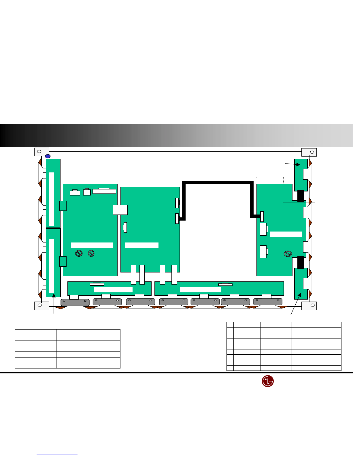
P3 P2
VR2 VR1
VR1
Y SUS B/D ASSY CTRL B/D ASSY
ZSUS B/D ASSY
X RIGHT B/D ASSY
Label
P2
P100
P300
P1
X LEFT B/D ASS’Y
P4
P6
P5
Y DRV Upper B/D ASSYY DRV Lower B/D ASSY
P1
P2
ⅡⅡⅡⅡ.... Module diagram & spec
Module diagram & specModule diagram & spec
Module diagram & spec
P'RT()O. p*+du,-(.am/0-a.da*d
1 6871QTH003B PWB(PCB)('SSY ZC)T(TOP(B23('SSY
26871 QZH002B PWB(PCB)('SSY ZSUS(B23('SSY(
36871 QTH004B PWB(PCB)('SSY ZC)T(BOTTOM(B23('SSY(
46871 Q4H012' PWB(PCB)('SSY X(45FT(BOTTOM(B23('SSY
56871 QRH010' PWB(PCB)('SSY X(RI6HT(BOTTOM(B23('SSY
66871 Q3P016B PWB(PCB)('SSY Y3RV(Upp/*(B23('SSY(
76871 Q3P017B PWB(PCB)('SSY Y3RV(4+w/*(B23('SSY(
86871 QYH015' PWB(PCB)('SSY YSUS(B23('SSY(
YDRV B/D ASSY
ZCNT TOP B/D ASSY
ZCNT BOTTOM B/D ASSY
5XT5R)'4(C'B45(CO))5CTIO)
5XT5R)'4(C'B45(CO))5CTIO)5XT5 R )'4(C ' B 45(CO))5CTIO)
5XT5R)'4(C'B45(CO))5CTIO)
,+../,-+* 0upp7y(08g.a7
P1~P2[X(B23] 5V,(15V,(V'
P3[Y(SUS( B23] VSC,(VS5TUP
P2[Y(SUS( B23] 5V,(15V,(VS
P1[Z(SUS(B23] 5V,(15V,(VS
P300[CTR4(B23] 5V
P100[CTR4(B23] ((((((((((((VI35O(SI6)'4
LG Electronics/DND QA
LG Electronics/DND QA LG Electronics/DND QA
LG Electronics/DND QA Gr
GrGr
Gr
YYYY----Board
BoardBoard
Board
Controller
ControllerController
Controller
Board
BoardBoard
Board
ZZZZ----Board
BoardBoard
Board
CN#
CN#C N#
CN#
CN2
CN2C N2
CN2
Local key
Local keyLocal key
Local key
EMI Filter
EMI FilterEMI Filter
EMI Filter
VSC
VSCVSC
VSC
Board
BoardBoard
Board
POWER
POWERPOWER
POWER
Board
BoardBoard
Board
X
X X
X – Board ( R )
Board ( R )Board ( R )
Board ( R )
X
X X
X – Board ( L )
Board ( L )Board ( L )
Board ( L )
Y
YY
Y-
--
- Drive
DriveDrive
Drive
Y
YY
Y-
--
- Drive
DriveDrive
Drive
Main Power
Main PowerMain Power
Main Power
LG Electronics/DND QA
LG Electronics/DND QA LG Electronics/DND QA
LG Electronics/DND QA Gr
GrGr
Gr
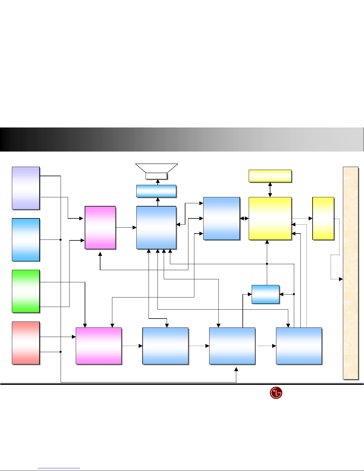
STB
STBSTB
STB
STB
STBSTB
STB
PC
PCPC
PC
PC
PCPC
PC
Video
VideoVideo
Video
Video
VideoVideo
Video
DVD
DVDDVD
DVD
DVD
DVDDVD
DVD
LA7222
LA7222LA7222
LA7222
LA7222
LA7222LA7222
LA7222
VPC3230
VPC3230VPC3230
VPC3230
VPC3230
VPC3230VPC3230
VPC3230
SDA94#0
SDA94#0SDA94#0
SDA94#0
SDA94#0
SDA94#0SDA94#0
SDA94#0
CXA2#0#
CXA2#0#CXA2#0#
CXA2#0#
CXA2#0#
CXA2#0#CXA2#0#
CXA2#0#
THS8083
THS8083THS8083
THS8083
THS8083
THS8083THS8083
THS8083
CXA2022S
CXA2022SCXA2022S
CXA2022S
CXA2022S
CXA2022SCXA2022S
CXA2022S
MX88L284
MX88L284MX88L284
MX88L284
MX88L284
MX88L284MX88L284
MX88L284
Buffer
BufferBuffer
Buffer
HC54#
HC54#HC54#
HC54#
Buffer
BufferBuffer
Buffer
HC54#
HC54#HC54#
HC54#
LA4282
LA4282LA4282
LA4282
LA4282
LA4282LA4282
LA4282
MICOM
MICOMMICOM
MICOM
CXP7500#0
CXP7500#0CXP7500#0
CXP7500#0
HC74
HC74HC74
HC74
HC74
HC74HC74
HC74
PDP MPDULE
PDP MPDULEPDP MPDULE
PDP MPDULE
2222MMMM----SDRAM
SDRAMSDRAM
SDRAM
2222MMMM----SDRAM
SDRAMSDRAM
SDRAM
Monitor Block diagram
Monitor Block diagramMonitor Block diagram
Monitor Block diagram
LG Electronics/DND QA
LG Electronics/DND QA LG Electronics/DND QA
LG Electronics/DND QA Gr
GrGr
Gr
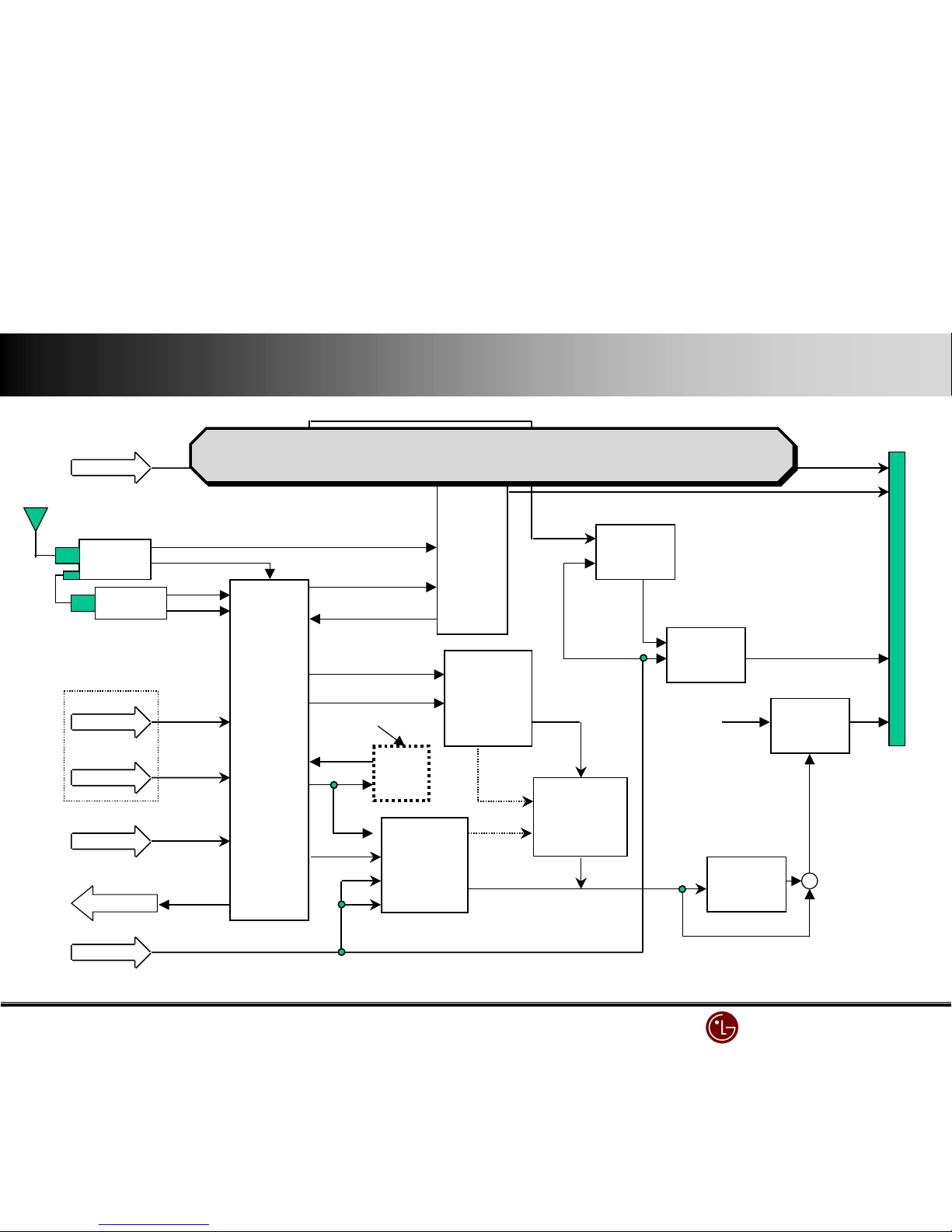
MICOM
EEPROM
X2416P
VIDEO
SWITCH
(M52758FP)
AUDIO
L
R
AUDIO AMP
LA4282(L&R)
5
5
RGBHV
RGBHV
3
H/V
SOG
COLOR DECODER
(VPC3230D)
DEINTERLACE
(FLI2200)
MEMORY
(4M-BYTE)
ENHANCER
(FLI2220)
COLOR CONTROL
&
VIDEO SWITCH
(CXA2101Q)
3
Y,Pb,Pr(STB)
3Y,Pb,Pr(MNT)
A/D CONVERTER
(CXA3516R)
SCALER
(JAG200)
MEMORY (6M-BYTE )
EPLD
(GEN. CLAMP)
Buffer
(74F574 x 4)
H
V
Clamp
2H/V
H
H
V
2PLLH/CLK
5
H/V/CLK/
HBLK/VBLK
4
H/V/DE/CLK
DISP_EN
5
RGBHV
3RGB
3RGB
5Y,U,V,H,V
Sound
Processor
(MSP3401G)
2H/V
MONOSTALE MULTIBIB.
SOG_OUT
CLAMP_AD
PORT EXP
(M62320X3)
ROM
(AT29C010)
(74HCT373)
YCbCr/
YPbPr
CVBS
2
YUV
41P
8
4
H/V/
FIELD/
LLC1
MN-42PZ10 VSC(JAG200 & FLI2200) Block Diagram
LG Electronics/DND QA
LG Electronics/DND QA LG Electronics/DND QA
LG Electronics/DND QA Gr
GrGr
Gr
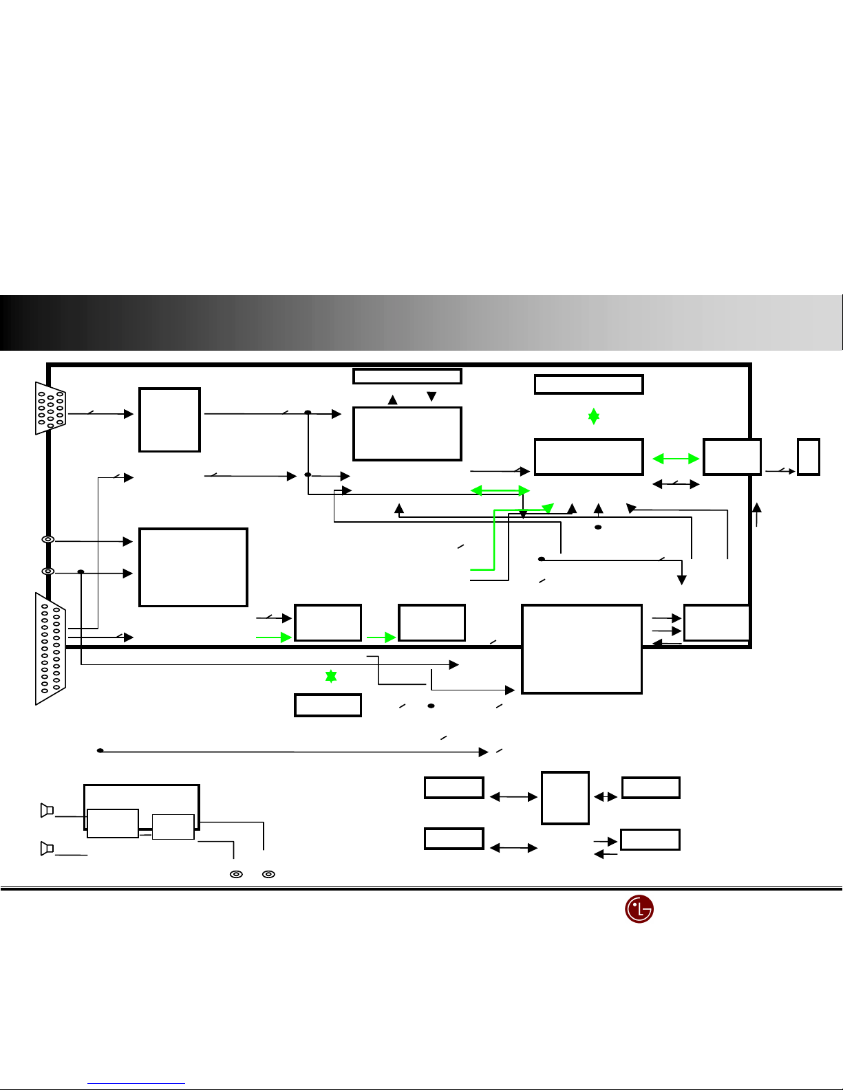
TUNER.1
9:;<
9:;<9:;<
9:;<1
CXA2069Q
A/V SW
V, L/R
V, L/R
S-VHS
Y / C
==== AUDIO >?
>?>?
>?
MSP3401G
Sound
Processor
2’nd SiF
L/R(tv)
DVD/DTV
(RCA JACK)
VPC3230D
(MAIN)
Vido
Proessor
Y,Cr,Cb (DVD)
DVD_Y
VPC3230D
(SUB)
Video
Proessor
MS81V04160
FRAME
MEMORY
PC
L / R
Y,Pb,Pr(DTV)
Y,Pb,Pr(DTV)
RGB(PC)
CVBS
RGB
M52758FP
RGB/YUV
S/W
DCF
RE
WE
RN-BA11(Tuner Receiver) Block - Diagram
RN-BA11(Tuner Receiver) Block - Diagram
Ro
Lo
Y/C
9:;<
9:;<9:;<
9:;<2
MNT_OUT
CVBS
Y/C
OPTION
TUNER.2
TV (M)
TV (S)
L/R(tv)
Y/C
M52756FP
RGB/YUV
S/W
RGB (DTV)
RGB(OSD)
LGTV1001
DRP
CXA2119M
S/W
+
YUV
L/R
LG Electronics/DND QA
LG Electronics/DND QA LG Electronics/DND QA
LG Electronics/DND QA Gr
GrGr
Gr
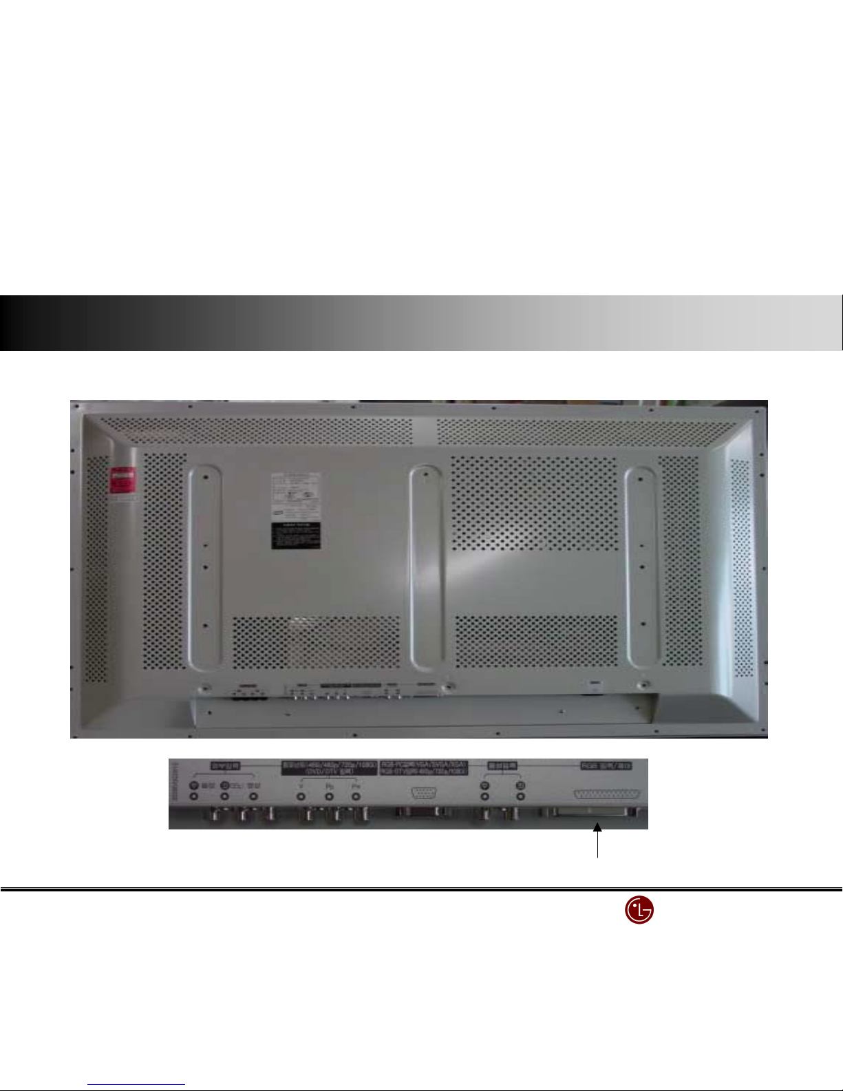
Connecting 25 Pin cable
Connecting 25 Pin cableConnecting 25 Pin cable
Connecting 25 Pin cable
(when connecting 25 Pin cable,
(when connecting 25 Pin cable,(when connecting 25 Pin cable,
(when connecting 25 Pin cable,
Connect external equipment to STB)
Connect external equipment to STB)Connect external equipment to STB)
Connect external equipment to STB)
Product back & monitor in/output section
Product back & monitor in/output sectionProduct back & monitor in/output section
Product back & monitor in/output section

LG Electronics/DND QA
LG Electronics/DND QA LG Electronics/DND QA
LG Electronics/DND QA Gr
GrGr
Gr
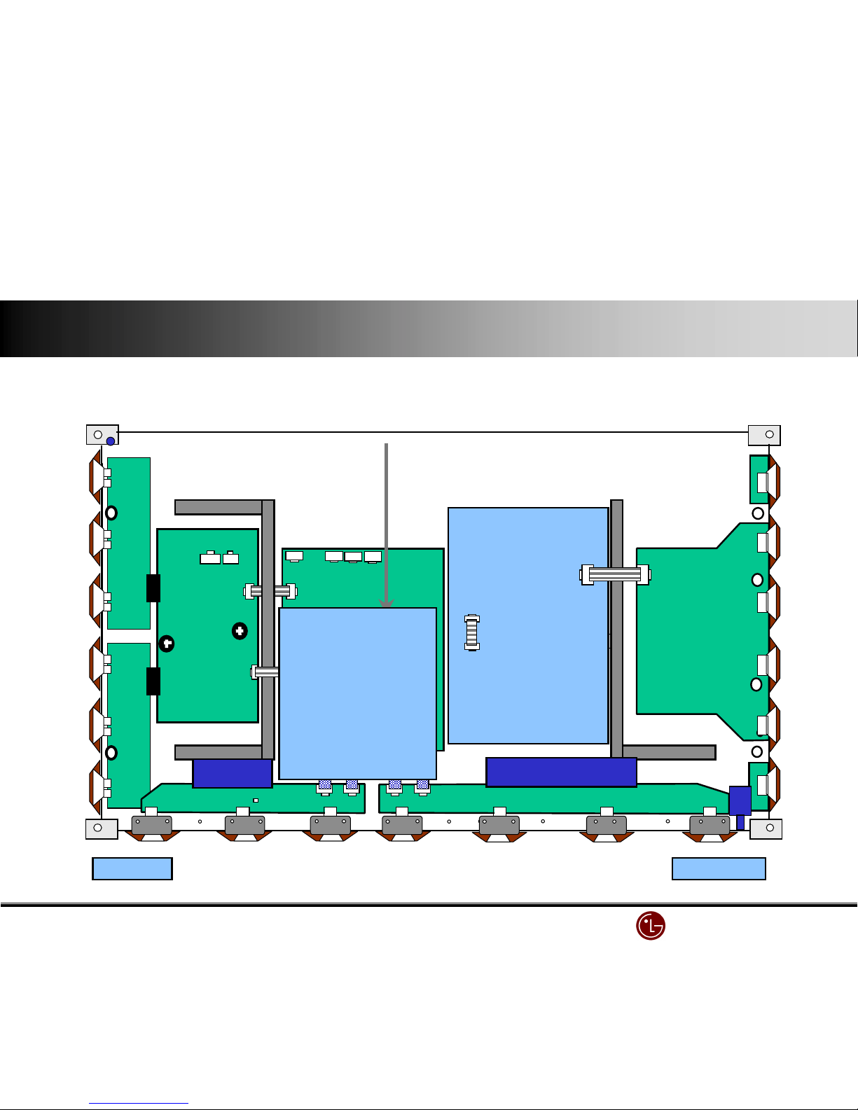
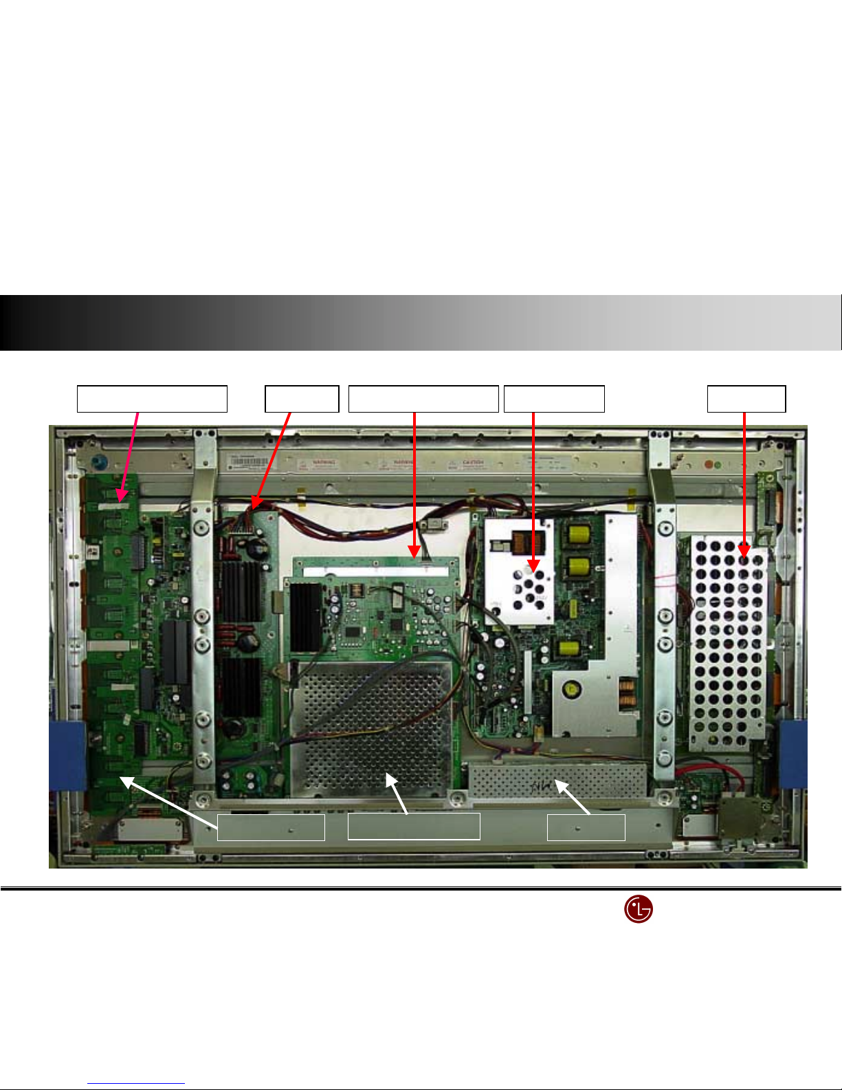
Power Board
Power BoardPower Board
Power Board
YYYY----Drive (TOP)
Drive (TOP)Drive (TOP)
Drive (TOP)
YYYY----Board
BoardBoard
Board
VSC Board
VSC BoardVSC Board
VSC Board
YYYY----Drive (Bottom)
Drive (Bottom)Drive (Bottom)
Drive (Bottom)
ZZZZ----Board
BoardBoard
Board
Controller Board
Controller BoardController Board
Controller Board
EMI Filter
EMI FilterEMI Filter
EMI Filter
Connection diagram (back cover
Connection diagram (back coverConnection diagram (back cover
Connection diagram (back cover’s open)
s open)s open)
s open)
LG Electronics/DND QA
LG Electronics/DND QA LG Electronics/DND QA
LG Electronics/DND QA Gr
GrGr
Gr
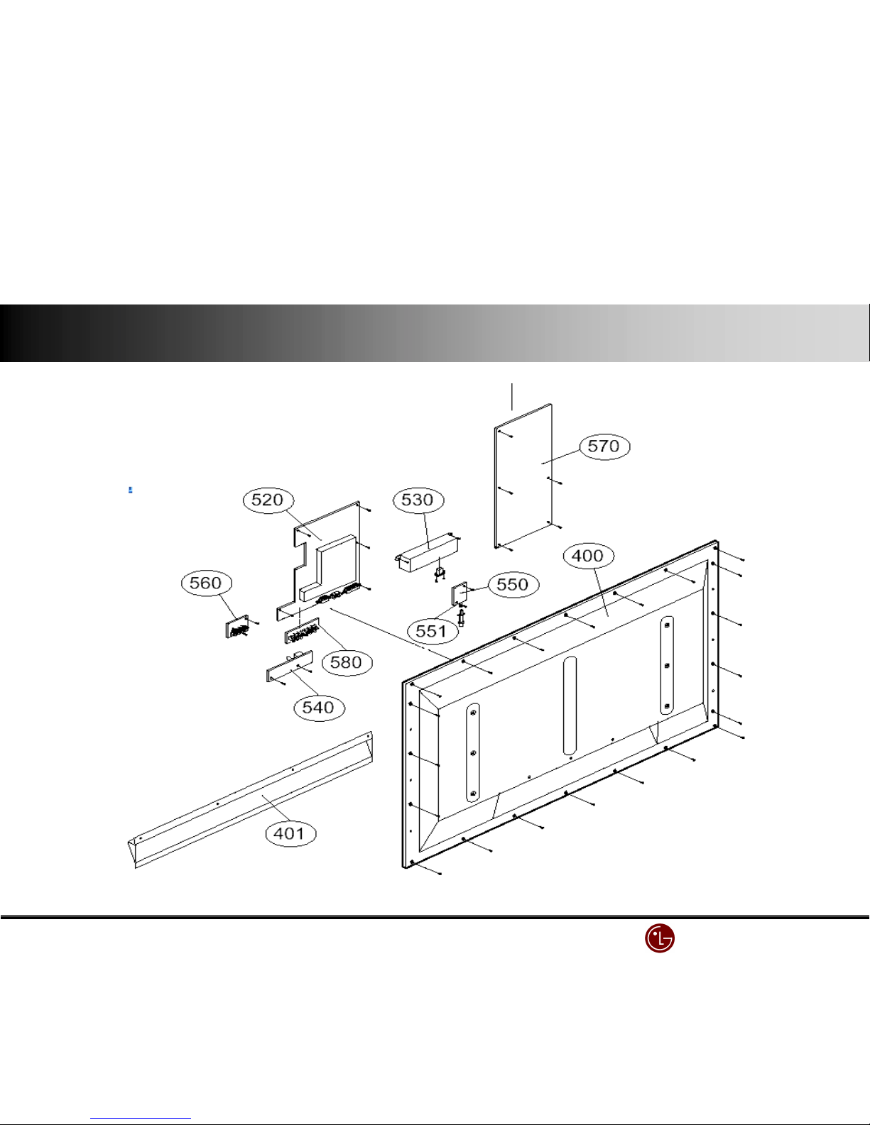
BACK COVER
BACK COVERBACK COVER
BACK COVER
POWER BOARD
POWER BOARDPOWER BOARD
POWER BOARDVSC BOARD
VSC BOARDVSC BOARD
VSC BOARDEMI Filter
EMI FilterEMI Filter
EMI Filter
Exploded view (Back Cover, VSC, EMI, Power )
Exploded view (Back Cover, VSC, EMI, Power )Exploded view (Back Cover, VSC, EMI, Power )
Exploded view (Back Cover, VSC, EMI, Power )
LG Electronics/DND QA
LG Electronics/DND QA LG Electronics/DND QA
LG Electronics/DND QA Gr
GrGr
Gr
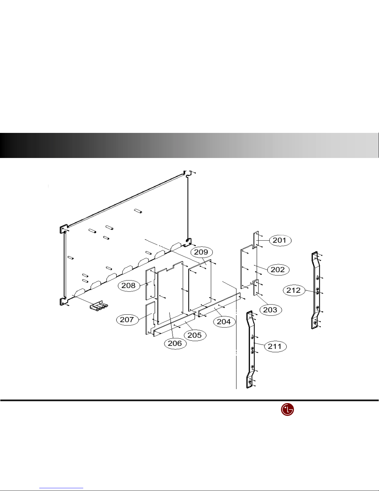
PANEL
PANELPANEL
PANEL
YYYY----BOARD
BOARDBOARD
BOARD
ZZZZ----BOARD
BOARDBOARD
BOARD
CONTROL
CONTROLCONTROL
CONTROL
BOARD
BOARDBOARD
BOARD
XXXX----BOARD
BOARDBOARD
BOARD
XXXX----BOARD
BOARDBOARD
BOARD
YYYY----Drive BOARD
Drive BOARDDrive BOARD
Drive BOARD
YYYY----Drive BOARD
Drive BOARDDrive BOARD
Drive BOARD
Exploded view (Module)
Exploded view (Module)Exploded view (Module)
Exploded view (Module)
LG Electronics/DND QA
LG Electronics/DND QA LG Electronics/DND QA
LG Electronics/DND QA Gr
GrGr
Gr
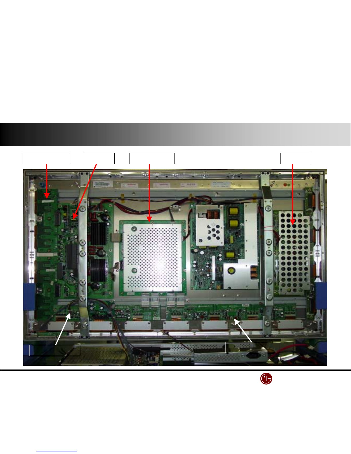
VSC Board(Front)
VSC Board(Front)VSC Board(Front)
VSC Board(Front)
EMI Filter
EMI FilterEMI Filter
EMI Filter
Power Board
Power BoardPower Board
Power Board ZZZZ----Board
BoardBoard
BoardYYYY----Board
BoardBoard
Board Control Board(Back)
Control Board(Back)Control Board(Back)
Control Board(Back)YYYY----Drive Board (Top)
Drive Board (Top)Drive Board (Top)
Drive Board (Top)
YYYY----3*8v/(B+a*d
3*8v/(B+a*d3*8v/(B+a*d
3*8v/(B+a*d
Main Power
Main Power Main Power
Main Power
Switch
SwitchSwitch
Switch
Parts (back covers open)
Parts (back covers open)Parts (back covers open)
Parts (back covers open)
LG Electronics/DND QA
LG Electronics/DND QA LG Electronics/DND QA
LG Electronics/DND QA Gr
GrGr
Gr
XXXX----Board ( Right)
Board ( Right) Board ( Right)
Board ( Right)
XXXX----Board ( Left )
Board ( Left )Board ( Left )
Board ( Left )
Control Board
Control BoardControl Board
Control Board ZZZZ----Board
BoardBoard
BoardYYYY----Board
BoardBoard
BoardYYYY----Drive Board
Drive BoardDrive Board
Drive Board
EMI Filter & VSC Board are separated
EMI Filter & VSC Board are separatedEMI Filter & VSC Board are separated
EMI Filter & VSC Board are separated

LG Electronics/DND QA
LG Electronics/DND QA LG Electronics/DND QA
LG Electronics/DND QA Gr
GrGr
Gr
Power well power Board-Korean market Murata Power Board
Power Board ( SMPS )
Power Board ( SMPS )Power Board ( SMPS )
Power Board ( SMPS )

LG Electronics/DND QA
LG Electronics/DND QA LG Electronics/DND QA
LG Electronics/DND QA Gr
GrGr
Gr
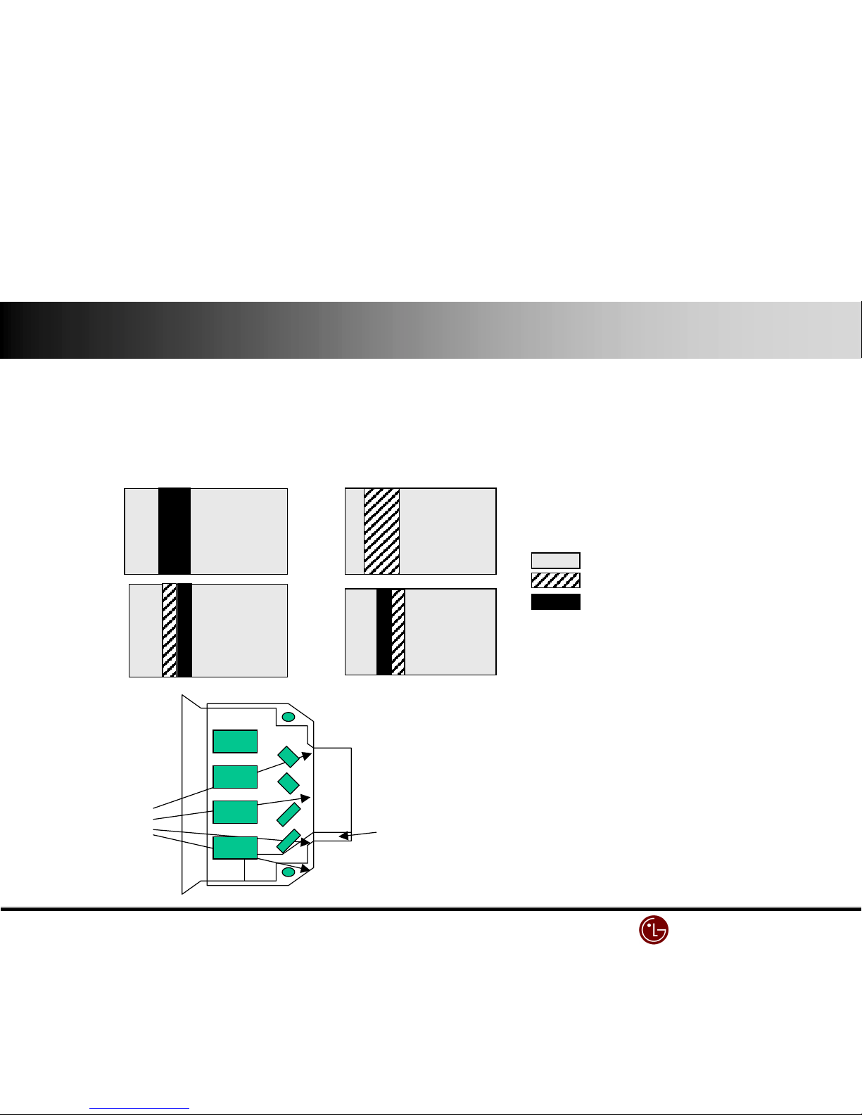
1. The 4/7 or 3/7 of screen is not displayed.
1) Check the X B/D power connector.
2) Check the connector between CTRL B/D and X B/D.
3) Replace the X B/D.
"
""
" relations between screen and X B/D
screen X B/D
left 4/7 of screen ↔ Right X B/D
right 3/7 of screen ↔ Left X B/D
"
""
" type
i) screen’s left(4/7)
ii) Screen’s right(3/7)
Non-displaying part
Displaying part
ⅢⅢⅢⅢ.... Screen defect diagnosis
LG Electronics/DND QA
LG Electronics/DND QA LG Electronics/DND QA
LG Electronics/DND QA Gr
GrGr
Gr
2. No image by Data COF. (the case one Data COF is totally or partially not displayed included)
1) It is mainly caused by related Data COF and X B/D connection error.
2) Check the connector between that Data COF & X B/D.
3) When Data COF has a defect, replace the related X B/D.
"
""
" examples of screen display type
( beside the below, any out of 7 Data COF can be occurred. )
partially displaying
ok
Non-image
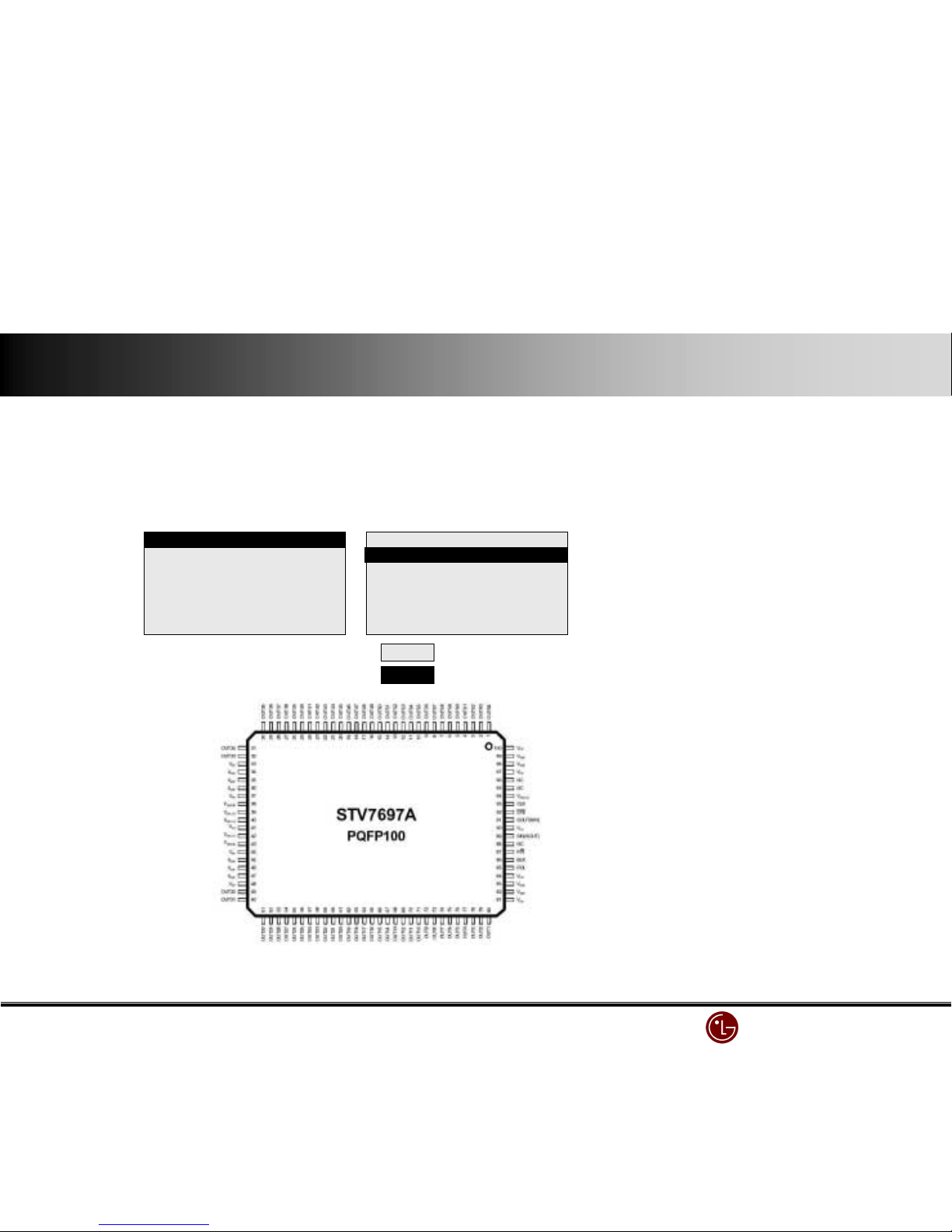
Set ① pattern( GND ) to ANODE,
② Pattern (resistance joint part ) to CATHOD,
Test diode forward and backward.
Measure @ resistance value.(10A)
① GND
②
resistance
"
""
" Data COF IC test method
LG Electronics/DND QA
LG Electronics/DND QA LG Electronics/DND QA
LG Electronics/DND QA Gr
GrGr
Gr
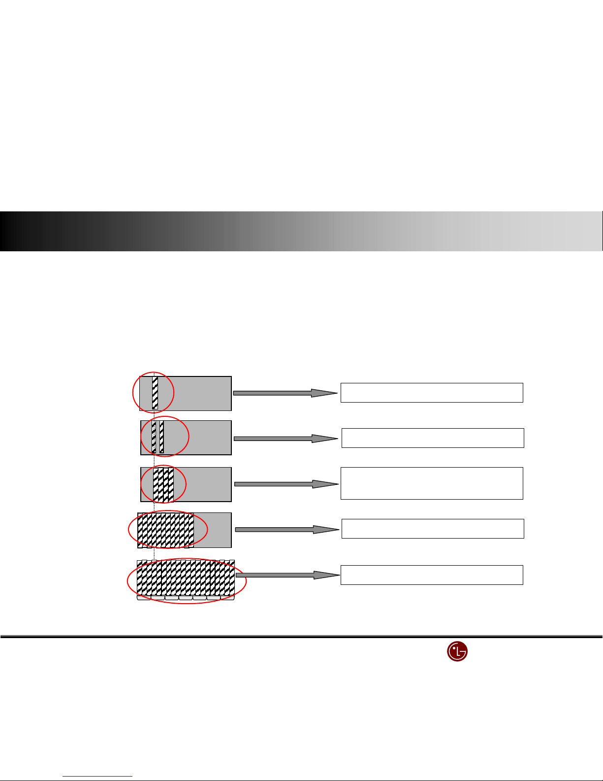
3. Data COF IC unit error
1) As pictures below, this is caused by the clock error of Data COF IC
2) With <case 1>, <case 2>, <case 3>, check Data COF connector and replace the X B/D.
3) With <case 4>, <case 5>, check the connector between CTRL B/D & X B/D and replace X B/D or CTRL B/D.
"
""
" Cases
Two every-second IC error in one
<case 1>
4 IC errors in one COF
<case 2>
Data COF IC unit error in the whole X B/D
<case 3>
Data COF IC unit error in the whole screen.
<case 4>
One IC error in one COF
<case 5>
LG Electronics/DND QA
LG Electronics/DND QA LG Electronics/DND QA
LG Electronics/DND QA Gr
GrGr
Gr
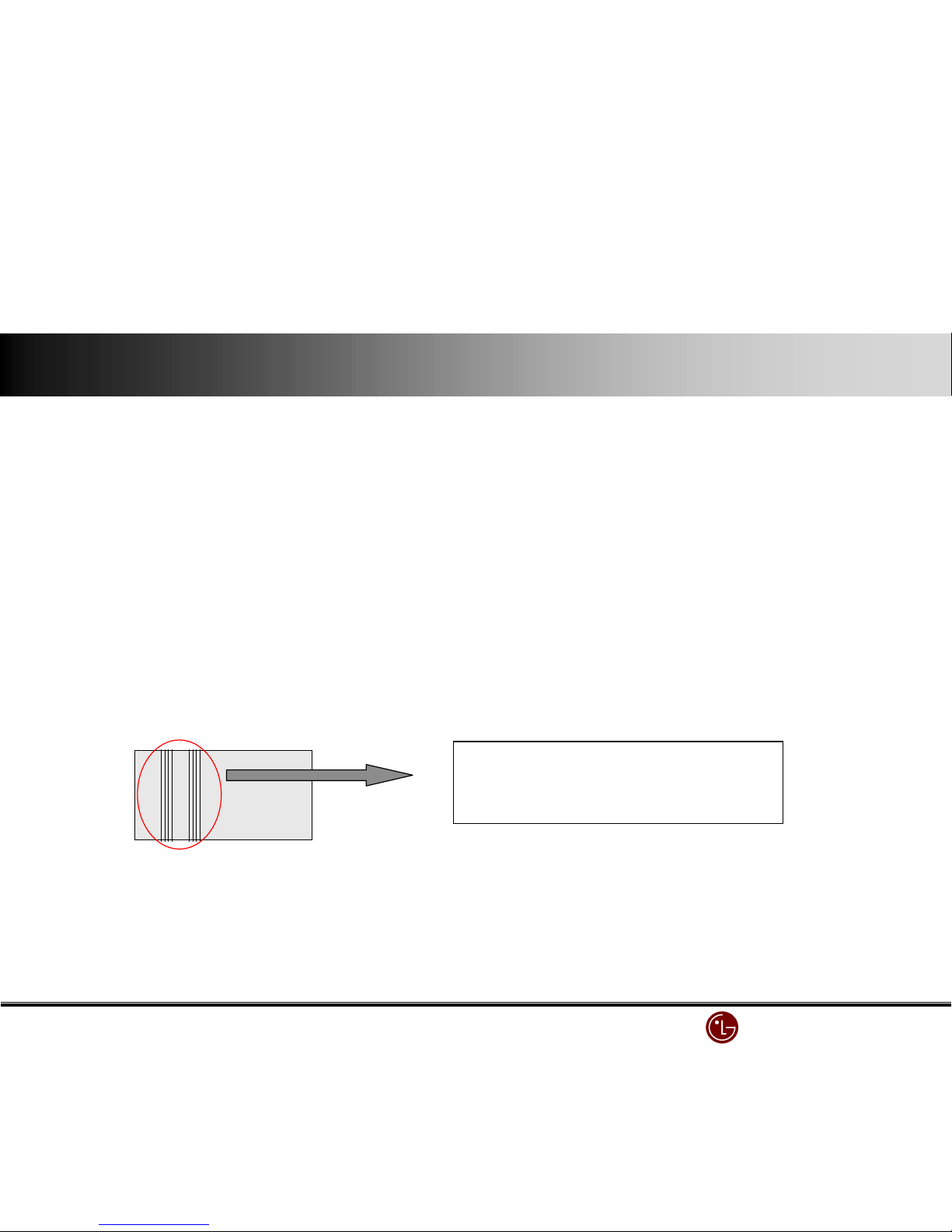
"
""
" case
Partial error or total error with One or more ICs
defect.
4. Regular vertical line with one or more Data COF IC
1) Regular vertical line with one Data COF IC is mainly caused by X B/D output terminal buffer’s output error. When two Data COF ICs have regular
vertical lines, it means the data transfer from Controller B/D to X B/D has an error.
2) Check the related X B/D connector.
3) Replace that X B/D or CTRL B/D
screen X B/D
left 4/7 of bottom screen ↔ Right X B/D
right 3/7 of bottom screen ↔ Left X B/D
"
""
" relation between screen & X B/D
LG Electronics/DND QA
LG Electronics/DND QA LG Electronics/DND QA
LG Electronics/DND QA Gr
GrGr
Gr
5. The screen by Scan FFC is not displayed
1) It is mainly caused by the bad connection between Scan FFC & Y B/D.
2) Check the related connector between Scan COF & Y B/D.
3) When Scan IC has a defect, replace the related Y DRV B/D.
"
""
" case
1/8 of the screen
total or partial non- image
"
""
" SCAN IC check
Set Vpp Pin to ANODE, GND pin to CATHOD and test diode forward and backward.
OK
B
B
B
 Loading...