

LG 42LGX User Manual
Please read this manual carefully before operating
your set.
Retain it for future reference.
Record model number and serial number of the set.
See the label attached on the back cover and quote
this information to your dealer
when you require service.
LCD TV PLASMA TV
OWNER’S MANUAL
LCD TV MODELS
32LG30 37LG50
37LG30 42LG50
42LG30 47LG50
42LGX 52LG50
32LG60 32LG70
37LG60 42LG70
42LG60 47LG70
47LG60 52LG70
52LG60
47LG90
PLASMA TV MODELS
42PG25
50PG25
50PG60
60PG60
50PG70
60PG70
P/NO : SAC30708020 (0805-REV06)
www.lgusa.com / www.lg.ca
As an ENERGY STAR Partner
LG Electronics USA, Inc.
has determined that this
product meets the ENERGY
STAR guidelines for energy
efficiency.
ENERGY STAR is a set of power-saving
guidelines issued by the U.S.
Environmental Protection Agency (EPA).
A
WARNING / CAUTION
WARNING / CAUTION
To prevent fire or shock hazards, do not expose
this product to rain or moisture.
FCC NOTICE
Class B digital device
This equipment has been tested and found to comply
with the limits for a Class B digital device, pursuant to
Part 15 of the FCC Rules. These limits are designed
to provide reasonable protection against harmful
interference in a residential installation. This equipment
generates, uses and can radiate radio frequency energy
and, if not installed and used in accordance with the
instructions, may cause harmful interference to radio
communications. However, there is no guarantee that
interference will not occur in a particular installation.
If this equipment does cause harmful interference to
radio or television reception, which can be determined
by turning the equipment off and on, the user is
encouraged to try to correct the interference by one
or more of the following measures:
- Reorient or relocate the receiving antenna.
- Increase the separation between the equipment and
receiver.
- Connect the equipment to an outlet on a circuit
different from that to which the receiver is connected.
- Consult the dealer or an experienced radio/TV
technician for help.
Any changes or modifications not expressly approved
by the party responsible for compliance could void
the user’s authority to operate the equipment.
CAUTION
Do not attempt to modify this product in any way
without written authorization from LG Electronics.
Unauthorized modification could void the user’s
authority to operate this product
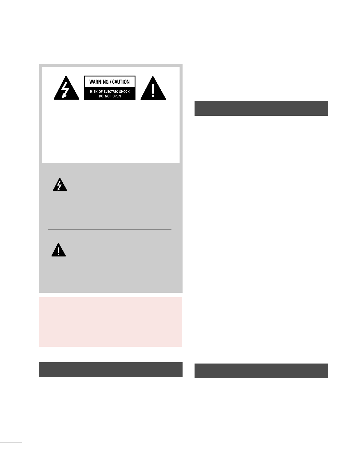
The lightning flash with arrowhead
symbol, within an equilateral triangle, is
intended to alert the user to the presence
of uninsulated “dangerous voltage” within the
product’s enclosure that may be of sufficient
magnitude to constitute a risk of electric shock to
persons.
The exclamation point within an equilateral
triangle is intended to alert the user to
the presence of important operating and
maintenance (servicing) instructions in the literature accompanying the appliance.
TO REDUCE THE RISK OF ELECTRIC SHOCK
DO NOT REMOVE COVER (OR BACK). NO
USER SERVICEABLE PARTS INSIDE. REFER TO
QUALIFIED SERVICE PERSONNEL.
WARNING/CAUTION
TO REDUCE THE RISK OF FIRE AND ELECTRIC
SHOCK, DO NOT EXPOSE THIS PRODUCT TO
RAIN OR MOISTURE.
NOTE TO CABLE/TV INSTALLER
This reminder is provided to call the CATV system
installer’s attention to Article 820-40 of the National
Electric Code (U.S.A.). The code provides guidelines for
proper grounding and, in particular, specifies that the
cable ground shall be connected to the grounding system
of the building, as close to the point of the cable entry
as practical.
1
IMPORTANT SAFETY INSTRUCTIONS
SAFETY INSTRUCTIONS
Read these instructions.
Keep these instructions.
Heed all warnings.
Follow all instructions.
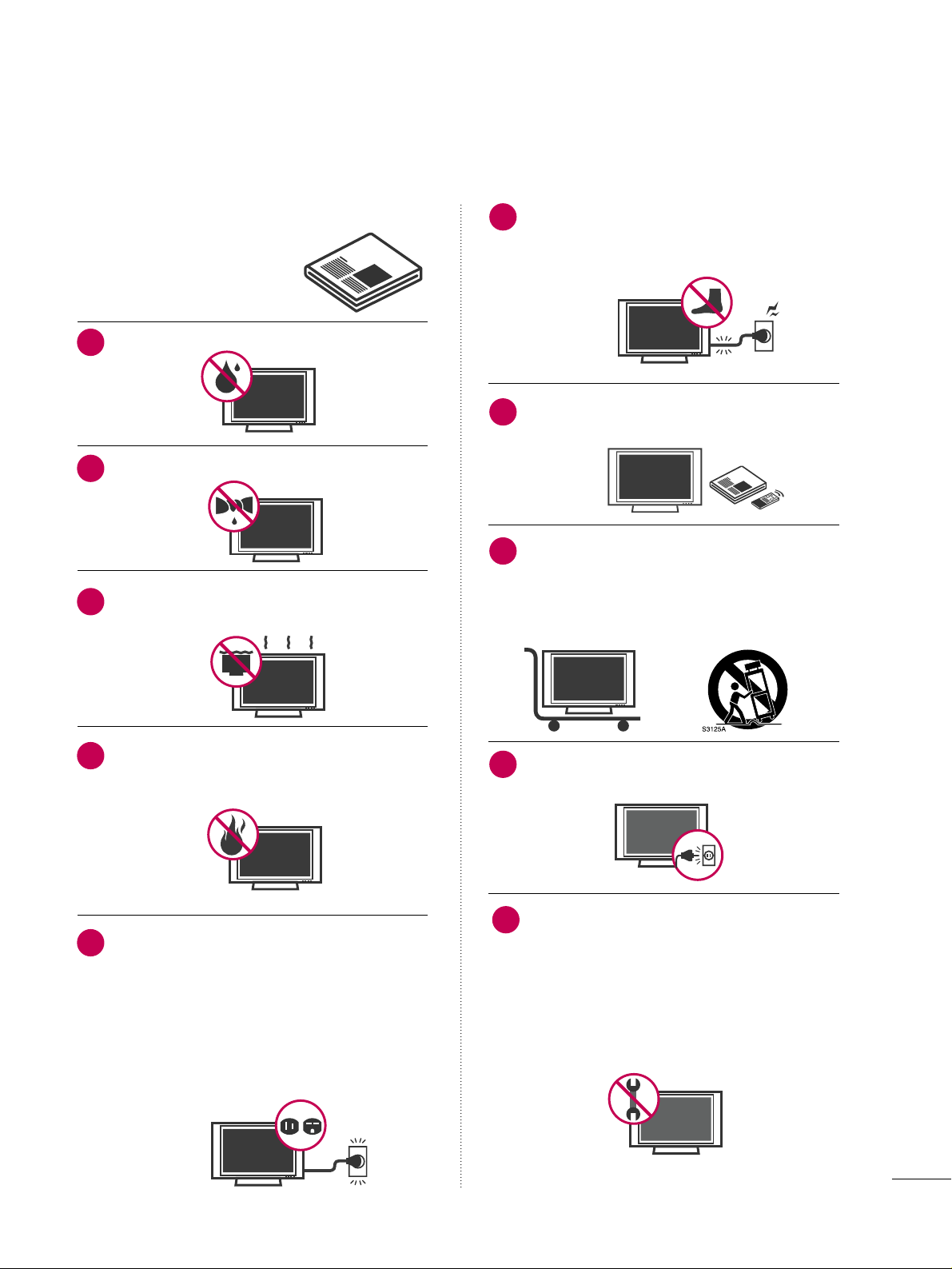
Do not use this apparatus near water.
Clean only with dry cloth.
Do not block any ventilation openings. Install in
accordance with the manufacturer’s instructions.
Do not install near any heat sources such as
radiators, heat registers, stoves, or other
apparatus (including amplifiers)that produce
heat.
Do not defeat the safety purpose of the polarized
or grounding-type plug. A polarized plug has
two blades with one wider than the other. A
grounding type plug has two blades and a
third grounding prong, The wide blade or the
third prong are provided for your safety. If the
provided plug does not fit into your outlet,
consult an electrician for replacement of the
obsolete outlet.
Protect the power cord from being walked on
or pinched particularly at plugs, convenience
receptacles, and the point where they exit from
the apparatus.
Only use attachments/accessories specified by
the manufacturer.
Use only with the cart, stand, tripod, bracket,
or table specified by the manufacturer, or sold
with the apparatus. When a cart is used, use
caution when moving the cart/apparatus combination to avoid injury from tip-over.
Unplug this apparatus during lighting storms
or when unused for long periods of time.
Refer all servicing to qualified service personnel.
Servicing is required when the apparatus has
been damaged in any way, such as powersupply cord or plug is damaged, liquid has
been spilled or objects have fallen into the
apparatus, the apparatus has been exposed to
rain or moisture, does not operate normally, or
has been dropped.
1
2
3
4
5
7
8
6
9
10
2
SAFETY INSTRUCTIONS
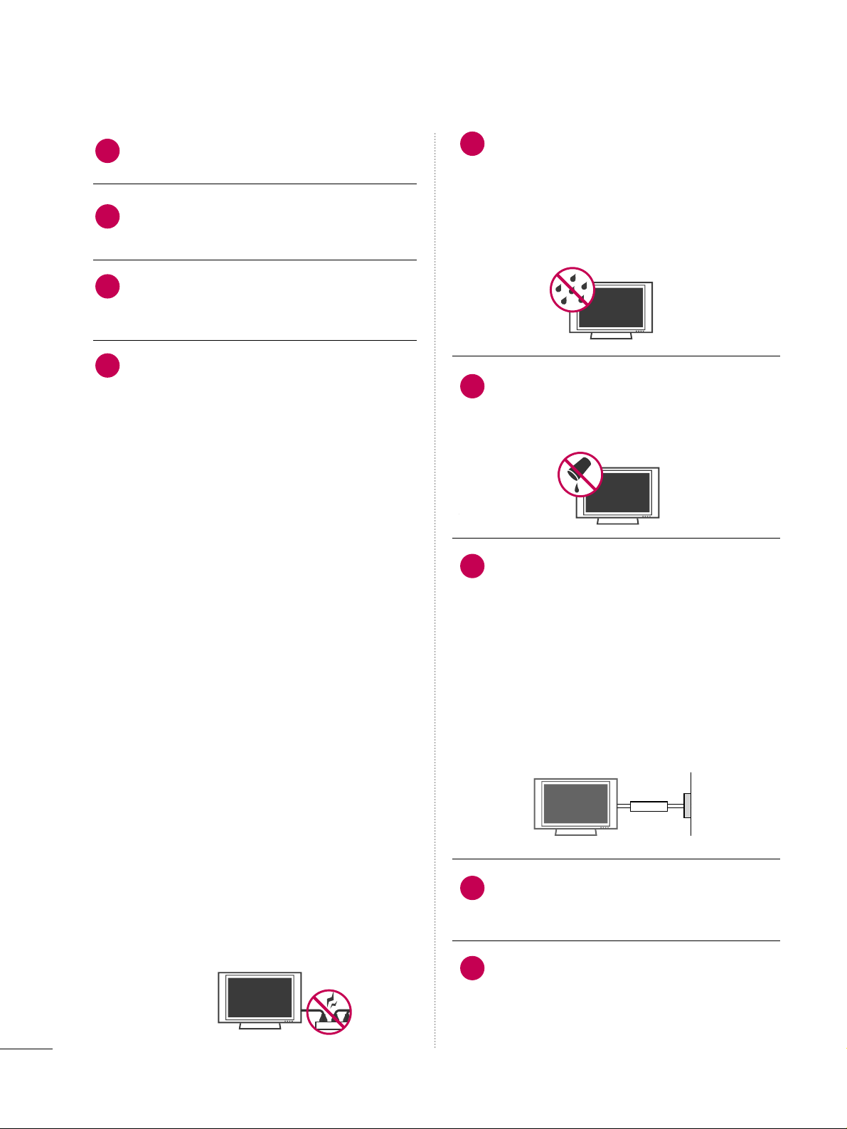
Never touch this apparatus or antenna during
a thunder or lighting storm.
When mounting a TV on the wall, make sure
not to install the TV by the hanging power and
signal cables on the back of the TV.
Do not allow an impact shock or any objects to
fall into the product, and do not drop onto the
screen with something.
CAUTION concerning the Power Cord:
It is recommend that appliances be placed
upon a dedicated circuit; that is, a single
outlet circuit which powers only that appliance
and has no additional outlets or branch
circuits. Check the specification page of this
owner's manual to be certain.
Do not connect too many appliances to the
same AC power outlet as this could result in
fire or electric shock.
Do not overload wall outlets. Overloaded wall
outlets, loose or damaged wall outlets, extension
cords, frayed power cords, or damaged or
cracked wire insulation are dangerous. Any of
these conditions could result in electric shock
or fire. Periodically examine the cord of your
appliance, and if its appearance indicates damage
or deterioration, unplug it, discontinue use of
the appliance, and have the cord replaced with
an exact replacement part by an authorized
servicer. Protect the power cord from physical
or mechanical abuse, such as being twisted,
kinked, pinched, closed in a door, or walked
upon. Pay particular attention to plugs, wall
outlets, and the point where the cord exits the
appliance.
Do not make the TV with the power cord
plugged in. Do not use a damaged or loose
power cord. Be sure do grasp the plug when
unplugging the power cord. Do not pull on the
power cord to unplug the TV.
WARNING - To reduce the risk of fire or electrical
shock, do not expose this product to rain,
moisture or other liquids. Do not touch the TV
with wet hands. Do not install this product
near flammable objects such as gasoline or
candles or expose the TV to direct air
conditioning.
Do not expose to dripping or splashing and do
not place objects filled with liquids, such as
vases, cups, etc. on or over the apparatus (e.g.
on shelves above the unit).
GGRROOUU NNDDIINNGG
Ensure that you connect the earth ground wire
to prevent possible electric shock (i.e. a TV
with a three-prong grounded AC plug must be
connected to a three-prong grounded AC outlet). If grounding methods are not possible,
have a qualified electrician install a separate
circuit breaker.
Do not try to ground the unit by connecting it
to telephone wires, lightening rods, or gas
pipes.
DDIISSCCOONNNNEECCTTIINNGG DDEEVVIICCEE FFRROOMM MMAAIINNSS
Mains plug is the disconnecting device. The
plug must remain readily operable.
Keep the product away from direct sunlight.
12
11
14
13
16
17
18
19
Power
Supply
Short-circuit
Breaker
15
3
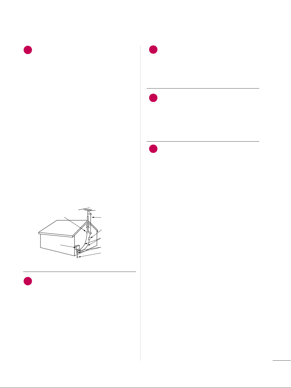
AANN TTEENNNN AASS
OOuuttddoooo rr aa nntteennnn aa ggrroouunnddii nngg
If an outdoor antenna is installed, follow the
precautions below. An outdoor antenna system
should not be located in the vicinity of overhead power lines or other electric light or
power circuits, or where it can come in contact
with such power lines or circuits as death or
serious injury can occur.
Be sure the antenna system is grounded so as
to provide some protection against voltage
surges and built-up static charges.
Section 810 of the National Electrical Code
(NEC) in the U.S.A. provides information with
respect to proper grounding of the mast and
supporting structure, grounding of the lead-in
wire to an antenna discharge unit, size of
grounding conductors, location of antenna discharge unit, connection to grounding electrodes and requirements for the grounding
electrode.
AAnntteennnnaa ggrroouunnddiinngg aaccccoorrddiinngg ttoo tthhee
NNaattiioonnaall EElleeccttrriiccaall CCooddee,, AANNSSII//NNFFPPAA 7700
CC lleeaa nniinn gg
When cleaning, unplug the power cord and
scrub gently with a soft cloth to prevent
scratching. Do not spray water or other liquids
directly on the TV as electric shock may occur.
Do not clean with chemicals such as alcohol,
thinners or benzene.
MMoovvii nngg
Make sure the product is turned off,
unplugged and all cables have been removed. It
may take 2 or more people to carry larger TVs.
Do not press against or put stress on the front
panel of the TV.
VV ee nnttii llaattii oo nn
Install your TV where there is proper ventilation. Do not install in a confined space such as
a bookcase. Do not cover the product with
cloth or other materials (e.g.) plastic while
plugged in. Do not install in excessively dusty
places.
If you smell smoke or other odors coming from
the TV or hear strange sounds, unplug the
power cord contact an authorized service center.
22
20
23
24
21
Antenna Lead in Wire
Antenna Discharge Unit
(NEC Section 810-20)
Grounding Conductor
(NEC Section 810-21)
Ground Clamps
Power Service Grounding
Electrode System (NEC
Art 250, Part H)
Ground Clamp
Electric Service
Equipment
NEC: National Electrical Code

4
CONTENTS
WARNING / CAUTION
. . . . . . . . . . . . . . . . . . . . . . . . . . . . A
SAFETY INSTRUCTIONS
. . . . . . . . . . . . . . . . . . . . . . . . . . 1
FEATURE OF THIS TV
. . . . . . . . . . . . . . . . . . . . . . . . . . . . . . . 6
PREPARATION
Accessories
. . . . . . . . . . . . . . . . . . . . . . . . . . . . . . . . . . . . . . . . . . . . . . . . . . . . . . 7
Front Panel Information . . . . . . . . . . . . . . . . . . . . . . . . . . . . . . . . . . . . . 8
Back Panel Information
. . . . . . . . . . . . . . . . . . . . . . . . . . . . . . . . . . . .
10
Stand Instruction
. . . . . . . . . . . . . . . . . . . . . . . . . . . . . . . . . . . . . . . . . . . . .
13
VESA Wall Mounting
. . . . . . . . . . . . . . . . . . . . . . . . . . . . . . . . . . . . . . . .
17
Cable Management
. . . . . . . . . . . . . . . . . . . . . . . . . . . . . . . . . . . . . . . . . .
18
Desktop Pedestal Installation
. . . . . . . . . . . . . . . . . . . . . . . . . . .
20
Swivel Stand
. . . . . . . . . . . . . . . . . . . . . . . . . . . . . . . . . . . . . . . . . . . . . . . . . . . 20
Attaching the TV to a Desk
. . . . . . . . . . . . . . . . . . . . . . . . . . . . . . 20
Securing the TV to the wall to prevent falling when
the TV is used on a stand
. . . . . . . . . . . . . . . . . . . . . . . . . . . . . . . .
21
Antenna or Cable Connection
. . . . . . . . . . . . . . . . . . . . . . . . . .
22
EXTERNAL EQUIPMENT SETUP
HD Receiver Setup
. . . . . . . . . . . . . . . . . . . . . . . . . . . . . . . . . . . . . . . . .
23
DVD Setup
. . . . . . . . . . . . . . . . . . . . . . . . . . . . . . . . . . . . . . . . . . . . . . . . . . . . .
29
VCR Setup
. . . . . . . . . . . . . . . . . . . . . . . . . . . . . . . . . . . . . . . . . . . . . . . . . . . . . 33
Other A/V Source Setup
. . . . . . . . . . . . . . . . . . . . . . . . . . . . . . . . . 36
PC Setup
. . . . . . . . . . . . . . . . . . . . . . . . . . . . . . . . . . . . . . . . . . . . . . . . . . . . . . . .
37
USB Connection
. . . . . . . . . . . . . . . . . . . . . . . . . . . . . . . . . . . . . . . . . . . .
46
Audio Out Connection . . . . . . . . . . . . . . . . . . . . . . . . . . . . . . . . . . . 47
WATCHING TV / CHANNEL CONTROL
Remote Control Functions
. . . . . . . . . . . . . . . . . . . . . . . . . . . . . . . 48
Turning On the TV
. . . . . . . . . . . . . . . . . . . . . . . . . . . . . . . . . . . . . . . . . .
50
Channel Selection
. . . . . . . . . . . . . . . . . . . . . . . . . . . . . . . . . . . . . . . . . . .
50
Volume Adjustment
. . . . . . . . . . . . . . . . . . . . . . . . . . . . . . . . . . . . . . . . .
50
Quick Menu
. . . . . . . . . . . . . . . . . . . . . . . . . . . . . . . . . . . . . . . . . . . . . . . . . . . .
51
Initial Setting
. . . . . . . . . . . . . . . . . . . . . . . . . . . . . . . . . . . . . . . . . . . . . . . . . .52
On-Screen Menus Selection
. . . . . . . . . . . . . . . . . . . . . . . . . . . .54
Channel Setup
- Auto Scan (Auto Tuning)
. . . . . . . . . . . . . . . . . . . . . . . . . . . 56
- Add / Delete Channel (Manual Tuning) . . . . . . 57
- Channel Editing
. . . . . . . . . . . . . . . . . . . . . . . . . . . . . . . . . . . . . . . .
58
Input List
. . . . . . . . . . . . . . . . . . . . . . . . . . . . . . . . . . . . . . . . . . . . . . . . . . . . . . . .59
Input Label
. . . . . . . . . . . . . . . . . . . . . . . . . . . . . . . . . . . . . . . . . . . . . . . . . . . . . 60
AV Mode
. . . . . . . . . . . . . . . . . . . . . . . . . . . . . . . . . . . . . . . . . . . . . . . . . . . . . . . .61
SIMPLINK
. . . . . . . . . . . . . . . . . . . . . . . . . . . . . . . . . . . . . . . . . . . . . . . . . . . . . . .
62
USB
Entry Modes . . . . . . . . . . . . . . . . . . . . . . . . . . . . . . . . . . . . . . . . . . . . . . . . . . .
64
Photo List
. . . . . . . . . . . . . . . . . . . . . . . . . . . . . . . . . . . . . . . . . . . . . . . . . . . . . . . 65
Music List
. . . . . . . . . . . . . . . . . . . . . . . . . . . . . . . . . . . . . . . . . . . . . . . . . . . . . . . 69
PICTURE CONTROL
Picture Size (Aspect Ratio) Control
. . . . . . . . . . . . . . . . . . 72
Preset Picture Settings
- Picture Mode - Preset
. . . . . . . . . . . . . . . . . . . . . . . . . . . . . . .
74
- Color Tone - Preset
. . . . . . . . . . . . . . . . . . . . . . . . . . . . . . . . . . . 75
Manual Picture Adjustment
- Picture Mode - User Mode
. . . . . . . . . . . . . . . . . . . . . . . .
76
- Picture Mode - Expert Control
. . . . . . . . . . . . . . . . . .
77
Picture Improvement Technology
. . . . . . . . . . . . . . . . . . . . . 78
Advanced Control - Black (Darkness) Level
. . . . . . .
79
Advanced Control - Eye Care
. . . . . . . . . . . . . . . . . . . . . . . . . . .
80
Advanced Control - Real Cinema/Film Mode
. . . . . 81
Advanced Control - TruMotion
. . . . . . . . . . . . . . . . . . . . . . . .
82
TruMotion Demo
. . . . . . . . . . . . . . . . . . . . . . . . . . . . . . . . . . . . . . . . . . . .
82
Local Dimming
. . . . . . . . . . . . . . . . . . . . . . . . . . . . . . . . . . . . . . . . . . . . . . . . 83
Local Dimming Demo
. . . . . . . . . . . . . . . . . . . . . . . . . . . . . . . . . . . . . .
83
Picture Reset
. . . . . . . . . . . . . . . . . . . . . . . . . . . . . . . . . . . . . . . . . . . . . . . . .
84
Power Indicator
. . . . . . . . . . . . . . . . . . . . . . . . . . . . . . . . . . . . . . . . . . . . . .
85
Image Sticking Minimization (ISM) Method
. . . . . .
86
Power Saving Picture Mode
. . . . . . . . . . . . . . . . . . . . . . . . . . . . . .
87

5
SOUND & LANGUAGE CONTROL
Auto Volume Leveler (Auto Volume) . . . . . . . . . . . . . . . . . 88
Preset Sound Settings (Sound Mode)
. . . . . . . . . . . . . . 89
Sound Setting Adjustment - User Mode
. . . . . . . . . . .
90
Clear Voice
. . . . . . . . . . . . . . . . . . . . . . . . . . . . . . . . . . . . . . . . . . . . . . . . . . . . . 91
Balance
. . . . . . . . . . . . . . . . . . . . . . . . . . . . . . . . . . . . . . . . . . . . . . . . . . . . . . . . . .
92
TV Speakers On/Off Setup
. . . . . . . . . . . . . . . . . . . . . . . . . . . . . .
93
Audio Reset
. . . . . . . . . . . . . . . . . . . . . . . . . . . . . . . . . . . . . . . . . . . . . . . . . . . 94
Stereo/SAP Broadcast Setup
. . . . . . . . . . . . . . . . . . . . . . . . . . . 95
Audio Language
. . . . . . . . . . . . . . . . . . . . . . . . . . . . . . . . . . . . . . . . . . . . . . 96
On-Screen Menus Language Selection
. . . . . . . . . . . . . . 97
Caption Mode
- Analog Broadcasting System Captions
. . . . . . .
98
- Digital Broadcasting System Captions
. . . . . . . .
99
- Caption Option
. . . . . . . . . . . . . . . . . . . . . . . . . . . . . . . . . . . . . 10 0
TIME SETTING
Clock Setting
- Auto Clock Setup
. . . . . . . . . . . . . . . . . . . . . . . . . . . . . . . . . . .
101
- Manual Clock Setup
. . . . . . . . . . . . . . . . . . . . . . . . . . . . . . . 102
Auto On/Off Time Setting . . . . . . . . . . . . . . . . . . . . . . . . . . . .
10 3
Sleep Timer Setting
. . . . . . . . . . . . . . . . . . . . . . . . . . . . . . . . . . . . . . .
10 4
Auto Shut-off Setting . . . . . . . . . . . . . . . . . . . . . . . . . . . . . . . . . . . . . 10 5
PARENTAL CONTROL / RATINGS
Set Password & Lock System
. . . . . . . . . . . . . . . . . . . . . . . . . .
10 6
Channel Blocking
. . . . . . . . . . . . . . . . . . . . . . . . . . . . . . . . . . . . . . . . . . 10 9
Movie & TV Rating
. . . . . . . . . . . . . . . . . . . . . . . . . . . . . . . . . . . . . . . .
110
Downloadable Rating
. . . . . . . . . . . . . . . . . . . . . . . . . . . . . . . . . . . . .
115
External Input Blocking
. . . . . . . . . . . . . . . . . . . . . . . . . . . . . . . . . . .
116
Key lock . . . . . . . . . . . . . . . . . . . . . . . . . . . . . . . . . . . . . . . . . . . . . . . . . . . . . . . . .
117
APPENDIX
Troubleshooting
. . . . . . . . . . . . . . . . . . . . . . . . . . . . . . . . . . . . . . . . . . . . . 118
Maintenance
. . . . . . . . . . . . . . . . . . . . . . . . . . . . . . . . . . . . . . . . . . . . . . . . . 12 0
Product Specifications . . . . . . . . . . . . . . . . . . . . . . . . . . . . . . . . . . .
121
Programming the Remote Control
. . . . . . . . . . . . . . . . . . 124
IR Codes
. . . . . . . . . . . . . . . . . . . . . . . . . . . . . . . . . . . . . . . . . . . . . . . . . . . . .127
External Control Through RS-232C
. . . . . . . . . . . . . . . . .12 9
Open Source License
. . . . . . . . . . . . . . . . . . . . . . . . . . . . . . . . . . . . . .13 6
6
FEATURE OF THIS TV
is a trademark of SRS Labs, Inc.
TruSurround XT technology is incorporated under
license from SRS Labs, Inc.
Manufactured under license from Dolby Laboratories.
“
Dolby
“and the double-D symbol are trademarks of
Dolby Laboratories.
THX (Thomlinson Holman’s Experiment) is the audio
and video certification standard of THX established
by George Lucas, who directed the movie Star Wars,
and Thomlinson.
This is the product to be certified in THX display area
and guarantees screen quality that exceeds the display
standard specification in both hardware and software.
FOR LCD TV
■
If the TV feels cold to the touch, there may be a small “flicker” when it is turned on. This is normal, there is
nothing wrong with TV.
■
Some minute dot defects may be visible on the screen, appearing as tiny red, green, or blue spots. However, they
have no adverse effect on the monitor's performance.
■
Avoid touching the LCD screen or holding your finger(s) against it for long periods of time. Doing so may produce
some temporary distortion effects on the screen.
On Disposal (Only Hg lamp used LCD TV)
The fluorescent lamp used in this product contains a small amount of mercury. Do not dispose of this product with
general household waste. Disposal of this product must be carried out in accordance to the regulations of your local
authority.
PREPARATION
7
PREPARATION
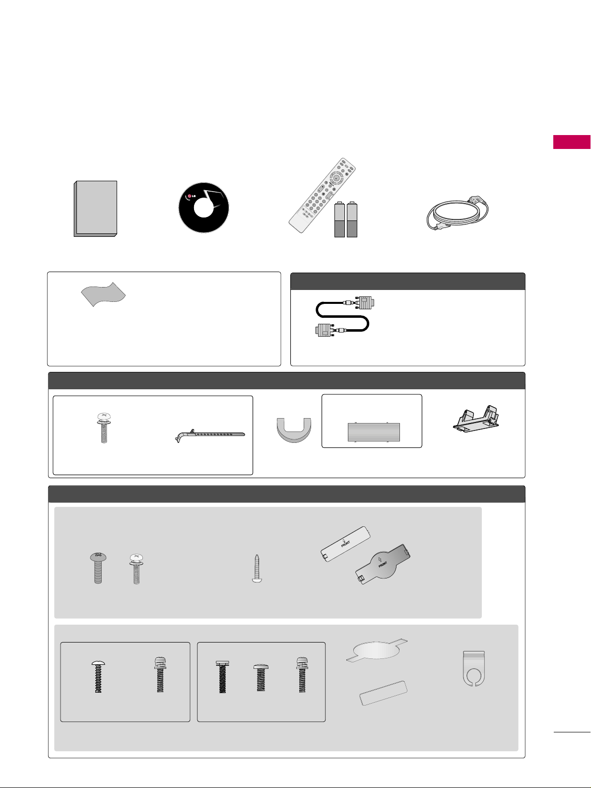
ACCESSORIES
Ensure that the following accessories are included with your TV. If an accessory is missing, please contact the
dealer where you purchased the TV.
The accessories included may differ from the images below.
OOppttiioonn EExxttrraass
FFoorr LLCCDD TTVV mmooddeellss
FFoorr PPllaassmmaa TTVV mmooddeellss
* Wipe spots on the exterior only with
the polishing cloth.
* Do not wipe roughly when removing
stain. Excessive pressure may cause
scratch or discoloration.
Polishing Cloth
(This feature is not available
for all models.)
Copyright© 2007 LGE,
All Rights Reserved.
D-sub 15 pin Cable
1.5V 1.5V
Owner’s Manual Power Cord
Remote Control,
Batteries
I
N
P
U
T
FAV
M
U
T
E
T
V
S
T
B
P
OW
E
R
Q
.
M
E
N
U
M
E
N
U
A
V
M
O
D
E
R
E
T
U
R
N
ENTER
V
O
L
C
H
123
456
78
0
9
F
L
A
S
H
B
K
P
A
G
E
D
V
D
V
C
R
CD Manual
When using the VGA (D-sub 15 pin
cable) PC connection, the user
must use shielded signal interface
cables with ferrite cores to maintain
standards compliance.
32/37/42LG30, 37/42/47/52LG50, 32/42/47/52LG70, 47LG90
Bolts for stand assembly
(Refer to P.16)
(Only 32/37/42LG30, 37/42LG50,
32/42LG70)
Protection Cover
Screw for stand fixing
(Refer to P.20)
(Only 32LG30/70,
42LG30/50)
x 4 x 4
32/37/42/47/52LG60, 42LGX
Protection Cover Cable Management
Clip
2EA 4EA 1EA 4EA 32LG60: 3EA
37LG60: 4EA
Bolts for stand assembly
(Refer to P.14)
(Only 32/37LG60)
(Only 42LG60, 42LGX)
Cable Management Clip
Protection Cover
(Only 50PG25,
50/60PG60, 50/60PG70)
(Only 42PG25)
or
or
Cable Holder
Bolts for stand assembly
(Refer to P.13)
x 4
PREPARATION
8
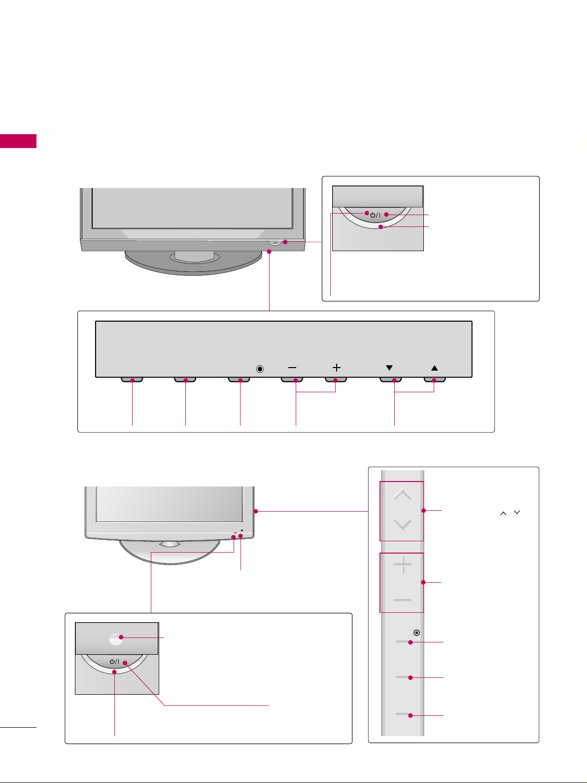
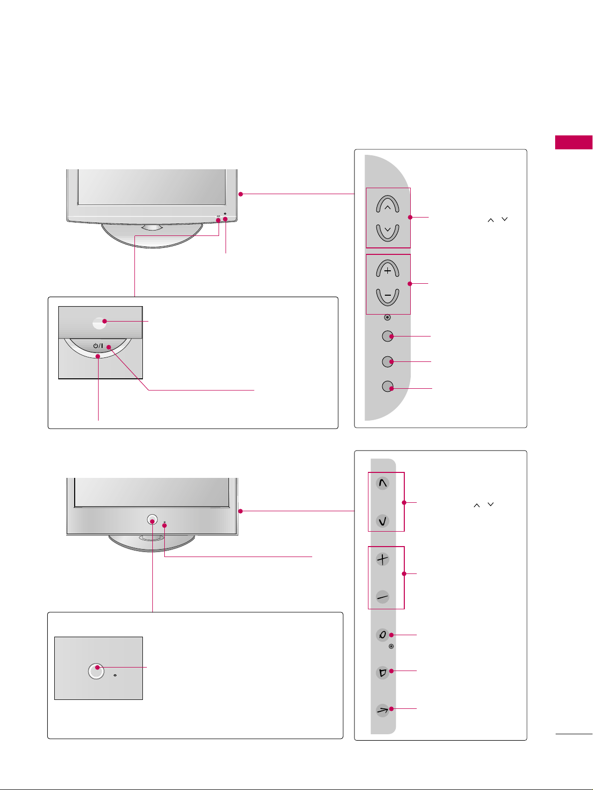
FRONT PANEL INFORMATION
PREPARATION
■
Image shown may differ from your TV.
■
NOTE: If your TV has a protection tape attached, remove the tape.
And then wipe the TV with a cloth (If a polishing cloth is included with your TV, use it).
Plasma TV Models
INPUT
Button
MENU
Button
ENTER
Button
VOLUME
(-, +) Buttons
CHANNEL
(
EE,DD
)Buttons
Remote Control Sensor
POWER Button
Power/Standby Indicator
Illuminates red in standby mode.
Illuminates blue when the TV is switched on.
LCD TV Models
POWER Button
Power/Standby Indicator
Illuminates red in standby mode.
Illuminates blue when the set is switched on.
(Can be adjusted using
PPoowweerr IInnddiiccaattoo rr
in
the OPTION menu.
GG
pp..8855
)
CHANNEL ( , )
Buttons
VOLUME (+, -)
Buttons
ENTER Button
MENU Button
INPUT Button
Intelligent Sensor
Adjusts picture according to the surrounding
conditions
32/42/47/52LG70, 47LG90
Remote Control Sensor
INPUT
MENU
ENTER
VOL
CH
CH
VOL
ENTER
MENU
INPUT
PREPARATION
9
LCD TV Models
POWER Button
Power/Standby Indicator
Illuminates red in standby mode.
Illuminates blue when the set is switched on.
(Can be adjusted using
PPoowweerr IInnddiiccaattoo rr
in
the OPTION menu.
GG
pp..8855
)
CHANNEL ( , )
Buttons
VOLUME (+, -)
Buttons
ENTER Button
MENU Button
INPUT Button
Intelligent Sensor
Adjusts picture according to the
surrounding conditions.
Intelligent Sensor (Except 32/37/42LG30)
Adjusts picture according to the surrounding
conditions
CHANNEL ( , )
Buttons
VOLUME (+, -)
Buttons
ENTER Button
MENU Button
INPUT Button
32/37/42LG30, 37/42/47/52LG50
32/37/42/47/52LG60, 42LGX
POWER Button
Remote Control Sensor
Power/Standby Indicator
Illuminates red in standby mode.
Illuminates white when the set is switched on.
(Can be adjusted using
PPoowweerr IInn ddiicc aattoo rr
in
the OPTION menu.
GG
pp..8855
)
Remote Control Sensor
CH
VOL
ENTER
MENU
INPUT
CH
VOL
ENTER
MENU
INPUT
PREPARATION
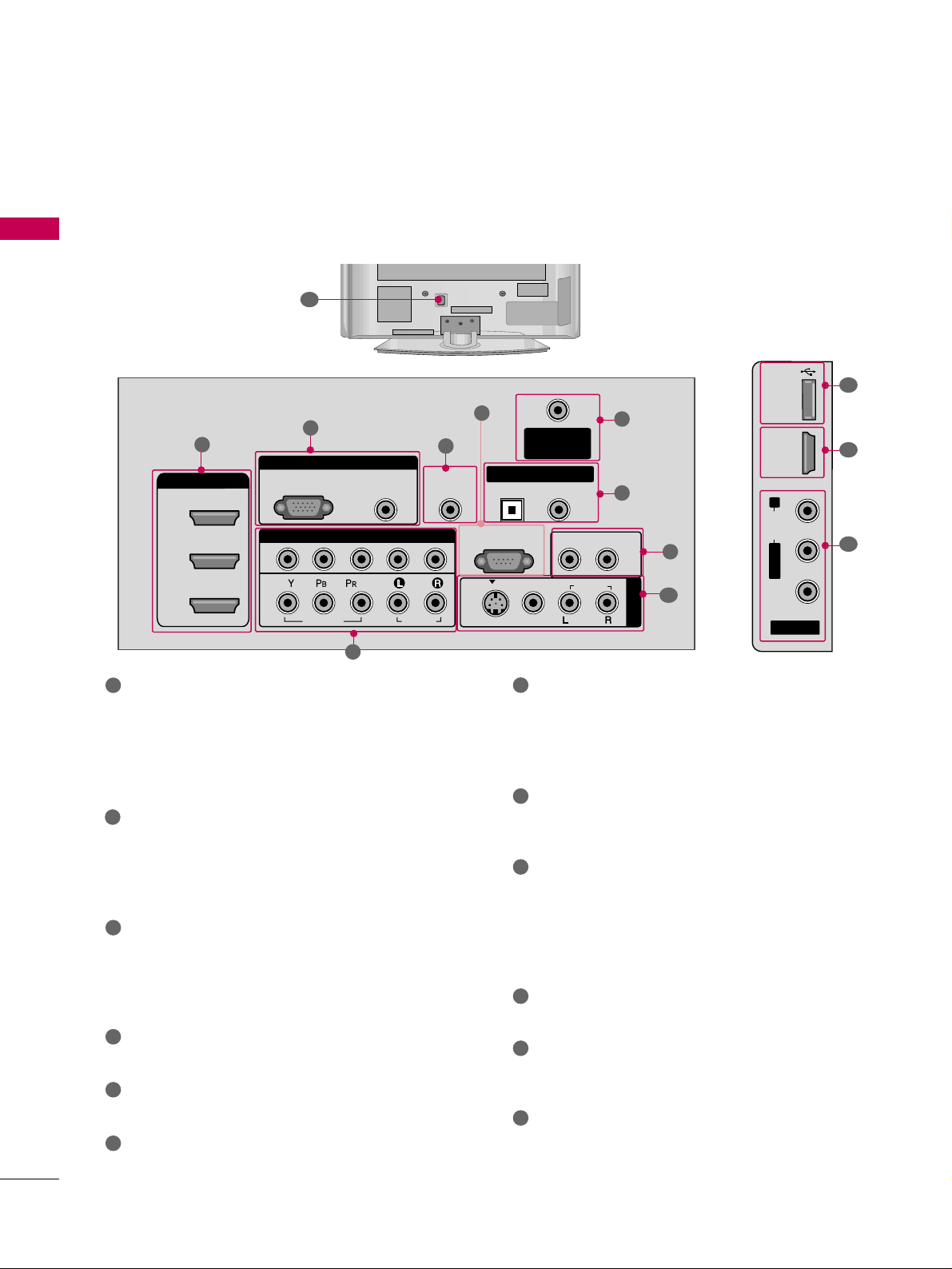
10
BACK PANEL INFORMATION
PREPARATION
Plasma TV Models
■
Image shown may differ from your TV.
R
12
AV IN 2
L/ MONO
R
AUDIO
VIDEO
USB IN
HDMI IN 4
9
10
1
R
RGB IN
COMPONENT IN
AUDIO
(RGB/DVI)
RGB(PC)
ANTENNA/
CABLE IN
1
2
RS-232C IN
(CONTROL & SERVICE)
VIDEO
AUDIO
VIDEO
AUDIO OUT
OPTICAL COAXIAL
MONO
( )
AUDIO
S-VIDEO
DIGITAL AUDIO OUT
AV IN 1
HDMI/DVI IN
3
2
1
REMOTE
CONTROL IN
1
3
4
6
7
8
2
9
5
HDMI/DVI IN, HDMI IN
Digital Connection.
Supports HD video and Digital audio. Doesn’t
support 480i.
Accepts DVI video using an adapter or HDMI to
DVI cable (not included).
COMPONENT IN
Analog Connection.
Supports HD.
Uses a red, green, and blue cable for video & red
and white for audio.
RGB (PC)
Analog PC Connection. Uses a D-sub 15 pin cable
(VGA cable).
AUDIO (RGB/DVI)
1/8” headphone jack for analog PC audio input.
REMOTE CONTROL IN PORT
For a wired remote control.
RS-232C IN (CONTROL & SERVICE) PORT
Used by third party devices.
ANTENNA/CABLE IN
Connect over-the air signals to this jack.
Connect cable signals to this jack.
DIGITAL AUDIO OUT
Digital audio output for use with amps and home
theater systems.
Includes an optical and/or coaxial connection.
Note: In standby mode, these ports do not work.
AUDIO OUT
Analog audio output for use with amps and home
theater systems.
AV (Audio/Video) IN
Analog composite connection. Supports standard
definition video only (480i).
S-VIDEO
Better quality than standard composition.
Supports standard definition video only (480i).
USB INPUT
Used for viewing photos and listening to MP3s.
USB SERVICE ONLY or RS-232C IN (SERVICE
ONLY)
Used for software updates.
Power Cord Socket
For operation with AC power.
Caution: Never attempt to operate the TV on DC
power.
1
2
3
4
5
6
9
10
11
12
7
8
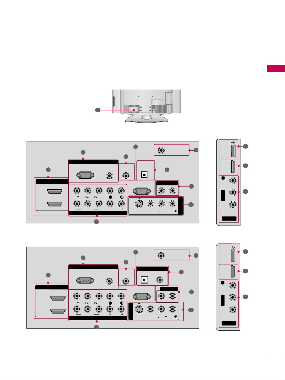
PREPARATION
11
LCD TV Models
AV IN 2
L/ MONO
R
AUDIO
VIDEO
HDMI IN 3 USB IN
RGB IN
COMPONENT IN
AUDIO
(RGB/DVI)
RGB(PC)
REMOTE
CONTROL IN
ANTENNA/
CABLE IN
1
2
RS-232C IN
(CONTROL & SERVICE)
VIDEO
AUDIO
OPTICAL COAXIAL
DIGITAL AUDIO OUT
AUDIO OUT
AV IN 1
R
HDMI/DVI IN
2
1
VIDEO
MONO
( )
AUDIO
S-VIDEO
1
3
4
6
7
8
2
9
9
5
RGB IN
COMPONENT IN
AUDIO
(RGB/DVI)
RGB(PC)
REMOTE
CONTROL IN
ANTENNA/
CABLE IN
1
2
RS-232C IN
(CONTROL & SERVICE)
VIDEO
AUDIO
DIGITAL
AUDIO OUT
OPTICAL
AUDIO OUT
AV IN 1
R
VIDEO
MONO
( )
AUDIO
S-VIDEO
2
1
HDMI/DVI IN
1
3
4
6
7
8
2
9
5
10
1
AV IN 2
L/ MONO
R
AUDIO
VIDEO
USB
SERVUCE ONLY
HDMI IN 3
9
11
1
37/42/47/52LG50, 32LG70
32/37/42LG30
R
12
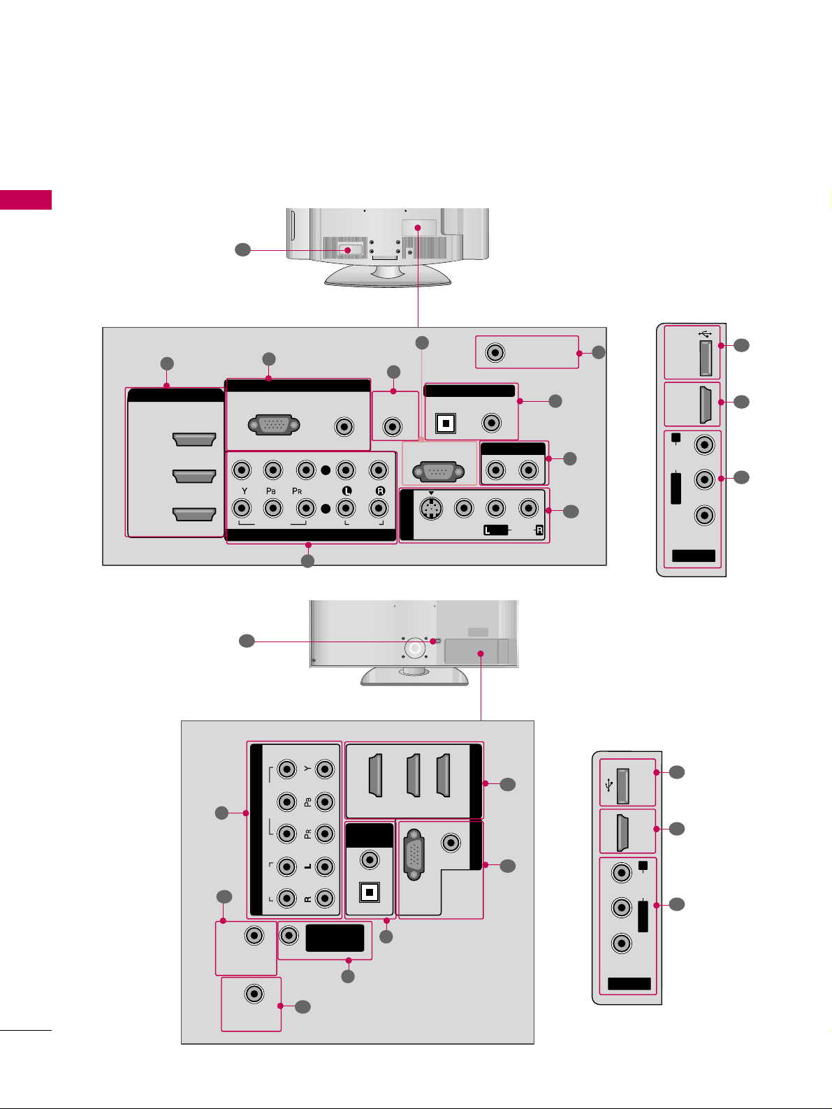
PREPARATION
12
PREPARATION
R
AV IN 2
L/ MONO
R
AUDIO
VIDEO
HDMI IN 4 USB IN
9
10
1
■
Image shown may differ from your TV.
32/37/42/47/52LG60, 42LGX
42/47/52LG70, 47LG90
LCD TV Models
R
12
12
RGB IN
COMPONENT IN
AUDIO
(RGB/DVI)
RGB(PC)
REMOTE
CONTROL IN
ANTENNA/
CABLE IN
RS-232C IN
(CONTROL & SERVICE)
VIDEO
AUDIO
OPTICAL COAXIAL
DIGITAL AUDIO OUT
AUDIO OUT
AV IN 1
R
HDMI/DVI IN
2
3
1
VIDEO
MONO
( )
AUDIO
S-VIDEO
2
1
1
3
4
6
7
8
2
9
5
AV IN
L/ MONO
R
AUDIO
VIDEO
HDMI IN 4 USB IN
9
10
1
(RGB/DVI)
AUDIO
RGB(PC)
REMOTE
CONTROL IN
RS-232C IN
(SERVICE ONLY)
OPTICAL
COAXIAL
DIGITAL
AUDIO OUT
R
123
COMPONENT IN
2
1
VIDEO
AUDIO
HDMI/DVI IN RGB IN
ANTENNA/
CABLE IN
2
7
4
1
3
6
11
PREPARATION
13
STAND INSTRUCTION
■
Image shown may differ from your TV.
Carefully place the TV screen side down on a
cushioned surface to protect the screen from
damage.
Assemble the TV as shown.
Fix the 4 bolts securely using the holes in the
back of the TV.
1
2
3
INSTALLATION (
Only 42PG25)
Plasma TV models
DETACHMENT
Carefully place the TV screen side down on a
cushioned surface to protect the screen from
damage.
1
Loose the bolts from TV.
2
42PG25 50PG25/60/70 60PG60/70
Detach the stand from TV.
3
After removing the stand, install the included
pprrootteeccttiioo nn ccoo vv ee rr
over the hole for the stand.
Press the
PPRROO TTEECC TTIIOO NN CCOOVVEERR
into the TV
until you hear it click.
PROTECTION COVER
GG
When assembling the desk type stand, make sure
the bolt is fully tightened (If not tightened fully,
the TV can tilt forward after the product installation). Do not over tighten.
NOTE
!
PREPARATION
14
PREPARATION
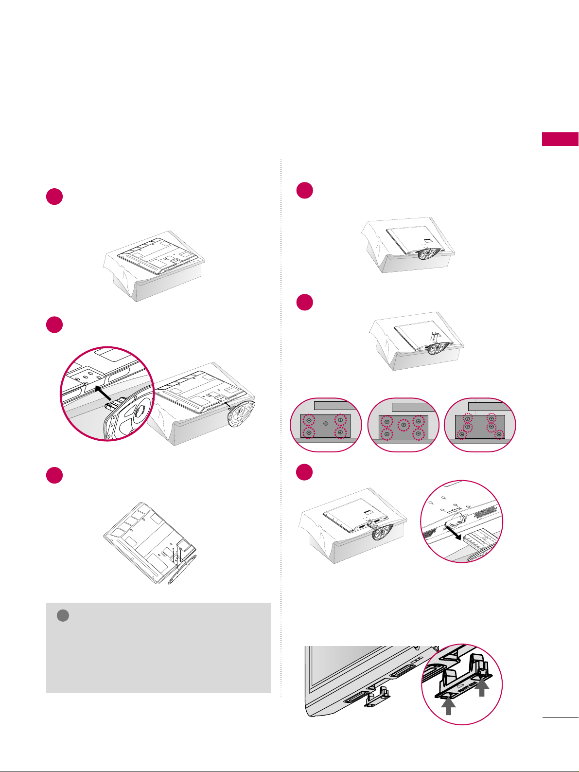
32/37/42/47/52LG60, 42LGX
Assemble the parts of the
SSTTAA NNDD BB OODDYY
with
CCOOVV EE RR BB AASSEE
of the TV.
2
Assemble the TV as shown.
3
Fix the 4 bolts securely using the holes in the
back of the TV.
4
Carefully place the TV screen side down on a
cushioned surface to protect the screen from
damage.
1
32LG60 37LG60 42LG60, 42LGX
SSTTAANNDD BBOO DDYY SSTTAANNDD BBOO DDYY
CCOOVV EE RR BB AASSEE
SSTTAANNDD BBOO DDYY
CCOOVV EE RR BB AASSEE
CCOOVV EE RR BB AASSEE
INSTALLATION (
Only 32/37/42LG60, 42LGX)
■
Image shown may differ from your TV.
GG
When assembling the desk type stand, make sure the
bolt is fully tightened (If not tightened fully, the TV
can tilt forward after the product installation). Do not
over tighten.
NOTE
!
PREPARATION
15
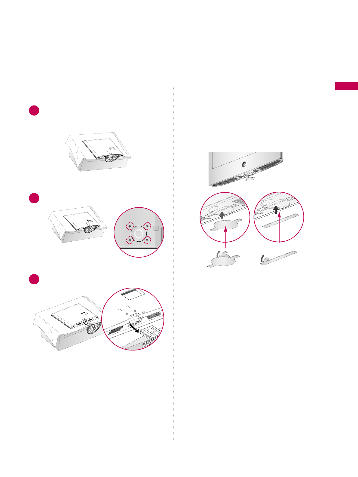
DETACHMENT
Carefully place the TV screen side down on a
cushioned surface to protect the screen from
damage.
1
Loose the bolts from TV.
2
Detach the stand from TV.
3
After removing the stand, install the included
pprr oo--
ttee ccttii oonn cc oovveerr
over the hole for the stand.
After removing the protection paper from the
protection cover, adhere it to the TV as shown.
PROTECTION COVER
PREPARATION
16
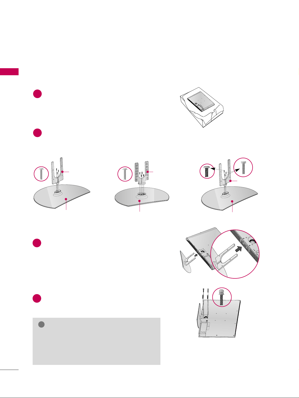
32/37/42LG30, 37/42/47/52LG50, 32/42/47/52LG70, 47LG90
PREPARATION
■
Image shown may differ from your TV.
Assemble the parts of the
SSTTAA NNDD BB OODDYY
with
CCOOVV EE RR BB AASSEE
of the TV.
2
Assemble the TV as shown.
3
Fix the 4 bolts securely using the holes in the
back of the TV.
4
SSTTAANNDD BBOO DDYY
CCOOVV EE RR BB AASSEE
Carefully place the TV screen side down on a cushioned surface to protect the screen from damage.
1
INSTALLATION
(
Only 32/37/42LG30, 37/42LG50, 32/42LG70)
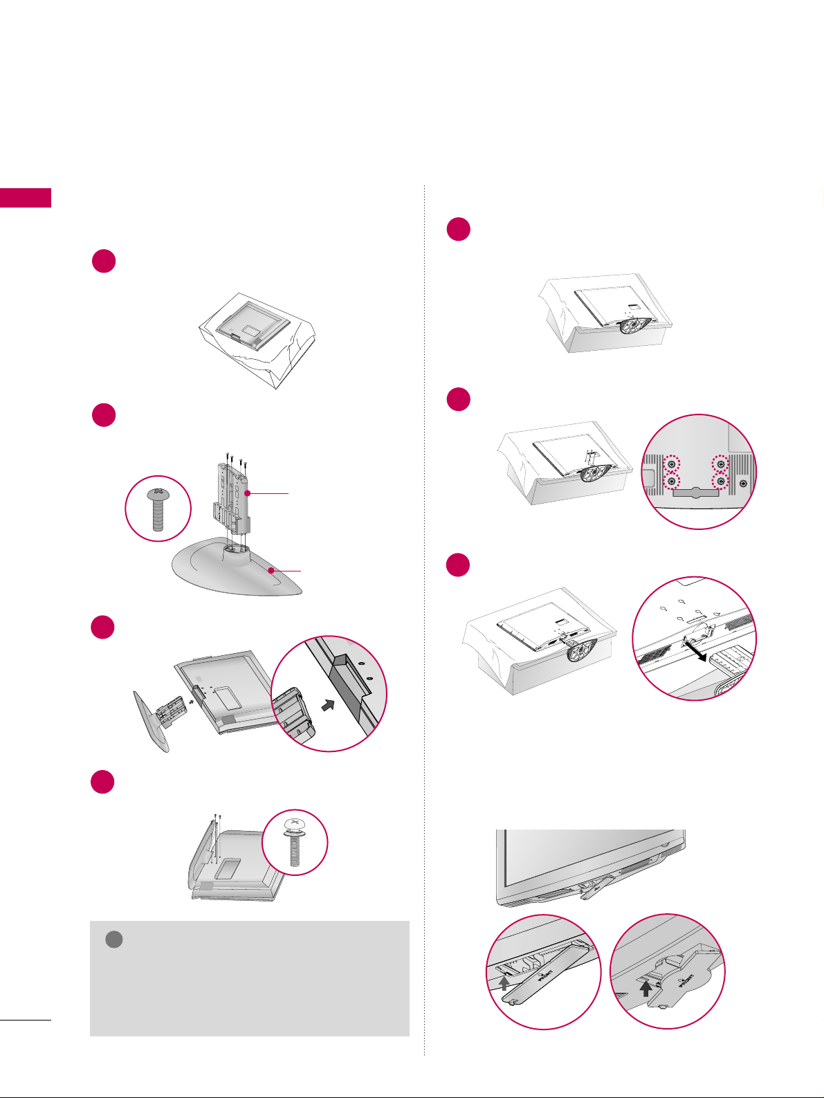
DETACHMENT
Carefully place the TV screen side down on a
cushioned surface to protect the screen from
damage.
1
Loose the bolts from TV.
2
Detach the stand from TV.
3
After removing the stand, install the included
pprrootteeccttiioo nn ccoo vv ee rr
over the hole for the stand.
Press the
PPRROO TTEECC TTIIOO NN CCOOVVEERR
into the TV
until you hear it click.
PROTECTION COVER
GG
When assembling the desk type stand, make sure
the bolt is fully tightened (If not tightened fully,
the TV can tilt forward after the product installation). Do not over tighten.
NOTE
!
PREPARATION
17
VESA WALL MOUNTING
Install your wall mount on a solid wall perpendicular to the floor. When attaching to other building materials, please
contact your nearest dealer.
If installed on a ceiling or slanted wall, it may fall and result in severe personal injury.
We recommend that you use an LG brand wall mount when mounting the TV to a wall.
LG recommends that wall mounting be performed by a qualified professional installer.
GG
Do not install your wall mount kit while your TV is turned on. It may result in personal injury due to electric
shock.
CAUTION
GG
Screw length needed depends on the wall mount
used. For further information, refer to the instructions included with the mount.
GG
Standard dimensions for wall mount kits are shown
in the table.
GG
When purchasing our wall mount kit, a detailed
installation manual and all parts necessary for
assembly are provided.
GG
Do not use screws longer then the standard dimension, as they may cause damage to the inside to
the TV.
GG
For wall mounts that do not comply with the VESA
standard screw specifications, the length of the
screws may differ depending on their specifications.
GG
Do not use screws that do not comply with the
VESA standard screw specifications.
Do not use fasten the screws too strongly, this may
damage the TV or cause the TV to a fall, leading to
personal injury. LG is not liable for these kinds of
accidents.
GG
LG is not liable for TV damage or personal injury
when a non-VESA or non specified wall mount is
used or the consumer fails to follow the TV installation instructions.
NOTE
!
AA
BB
Product Model
VESA
(A *B)
Standard Screw Quantity
32LG30, 32LG60, 32LG70
37LG30, 37LG60, 37LG50
42LG30, 42LG50, 42LG60, 42LG70, 42LGX
47LG50, 47LG60, 47LG70, 47LG90
52LG50, 52LG60, 52LG70
42PG25
50PG25, 50PG60, 50PG70
60PG60, 60PG70
200* 10 0
200* 200
800* 400
400* 400
600* 400
M4
M6
M6
M6
M8
4
4
4
4
4
LCD TV
PLASMA TV
PREPARATION
18
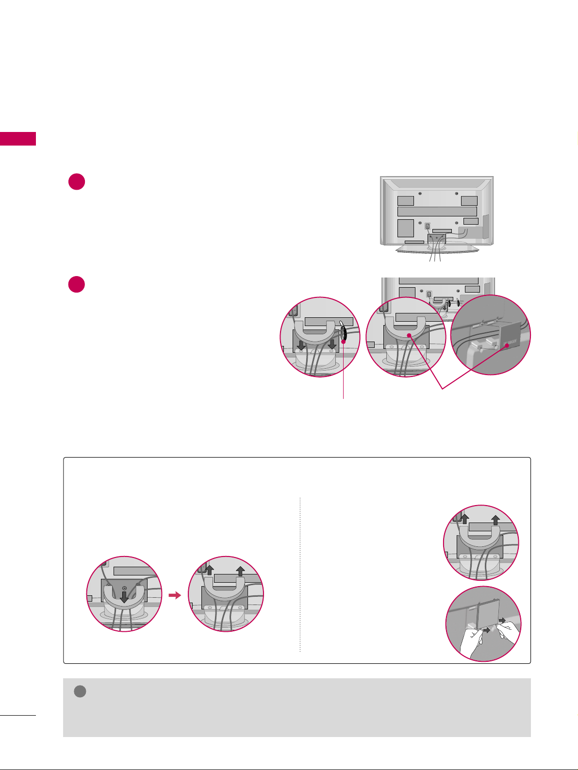
CABLE MANAGEMENT
PREPARATION
■
Image shown may differ from your TV.
Plasma TV Models
Connect the cables as necessary.
To connect additional equipment, see the
EXTERNAL EQUIPMENT SETUP section.
Install the CABLE MANAGEMENT CLIP as
shown.
If your TV has the CABLE HOLDER, install it
as shown and bundle the cables.
1
2
GG
Do not hold the CABLE MANAGEMENT CLIP when moving the TV.
- If the TV is dropped, you may be injured or the product may be broken.
NOTE
!
How to remove the CABLE MANAGEMENT CLIP
GG
First, press the cable management. Hold the
CCAABBLLEE MMAANNAA GGEE MMEE NNTT CCLLIIPP
with both
hands and pull it upward.
GG
Separate
CC AABBLLEE MM AANN--
AAGG EEMM EENN TT CCLLIIPP
from TV
by pressing two latches.
GG
Hold the CABLE MANAGEMENT CLIP with both
hands and pull it upward.
42PG25
50PG25, 50/60PG60, 50/60PG70
CABLE MANAGEMENT CLIP
CABLE HOLDER
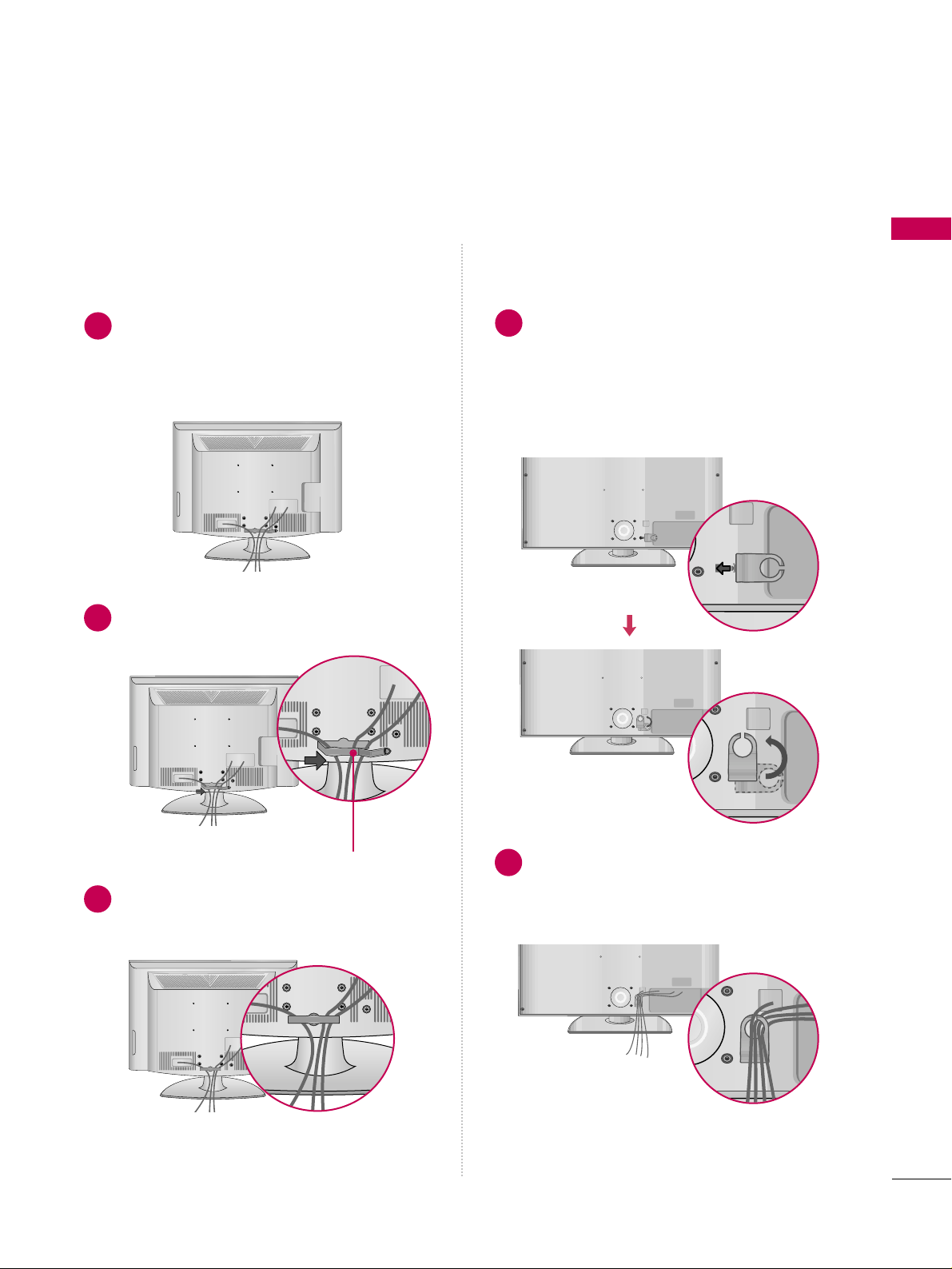
PREPARATION
19
LCD TV Models
Connect the cables as necessary.
To connect additional equipment, see the
EXTERNAL EQUIPMENT SETUP section.
Install the CABLE MANAGEMENT CLIP as
shown.
CABLE MANAGEMENT CLIP
1
2
Align the hole with the tab on the
CC AABBLLEE
MMAANN AAGGEEMMEENN TT CCLLIIPP
.
Turn the
CCAABBLLEE MMAANNAA GGEE MMEE NNTT CCLLIIPP
as
shown.
Note: This cable management clip can be bro-
ken by excessive pressure.
Connect the cables as necessary.
To connect additional equipment, see the
EXTERNAL EQUIPMENT SETUP section.
1
2
Put the cables inside the CABLE MANAGEMENT
CLIP and snap it closed.
3
32/37/42/47/52LG60, 42LGX32/37/42LG30, 37/42/47/52LG50,
32/42/47/52LG70, 47LG90
PREPARATION
20
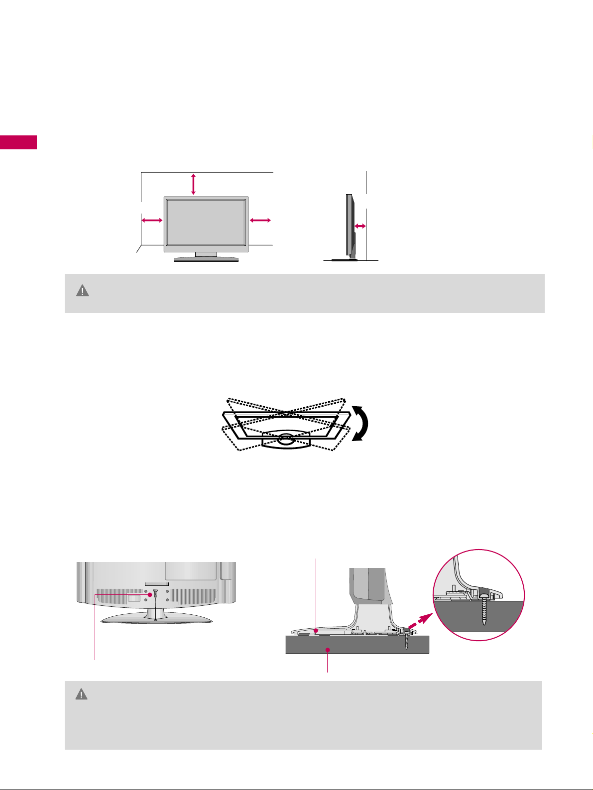
DESKTOP PEDESTAL INSTALLATION
PREPARATION
For proper ventilation, allow a clearance of 4 inches on all four sides from the wall.
■
Image shown may differ from your TV.
4 inches
4 inches
4 inches
4 inches
SWIVEL STAND
After installing the TV, you can adjust the TV set manually to the left or right direction by 20 degrees to suit
your viewing position.
GG
Ensure adequate ventilation by following the clearance recommendations.
GG
Do not mount near or above any type of heat source.
CAUTION
ATTACHING THE TV TO A DESK (Only 32LG30/70, 42LG30/50)
The TV must be attached to a desk so it cannot be pulled in a forward/backward direction, potentially causing
injury or damaging the product.
GG
To prevent TV from falling over, the TV should be securely attached to the floor/wall per installation
instructions. Tipping, shaking, or rocking the machine may cause injury.
WARNING
1-Screw
(provided as parts of the product)
Desk
Stand
PREPARATION
21
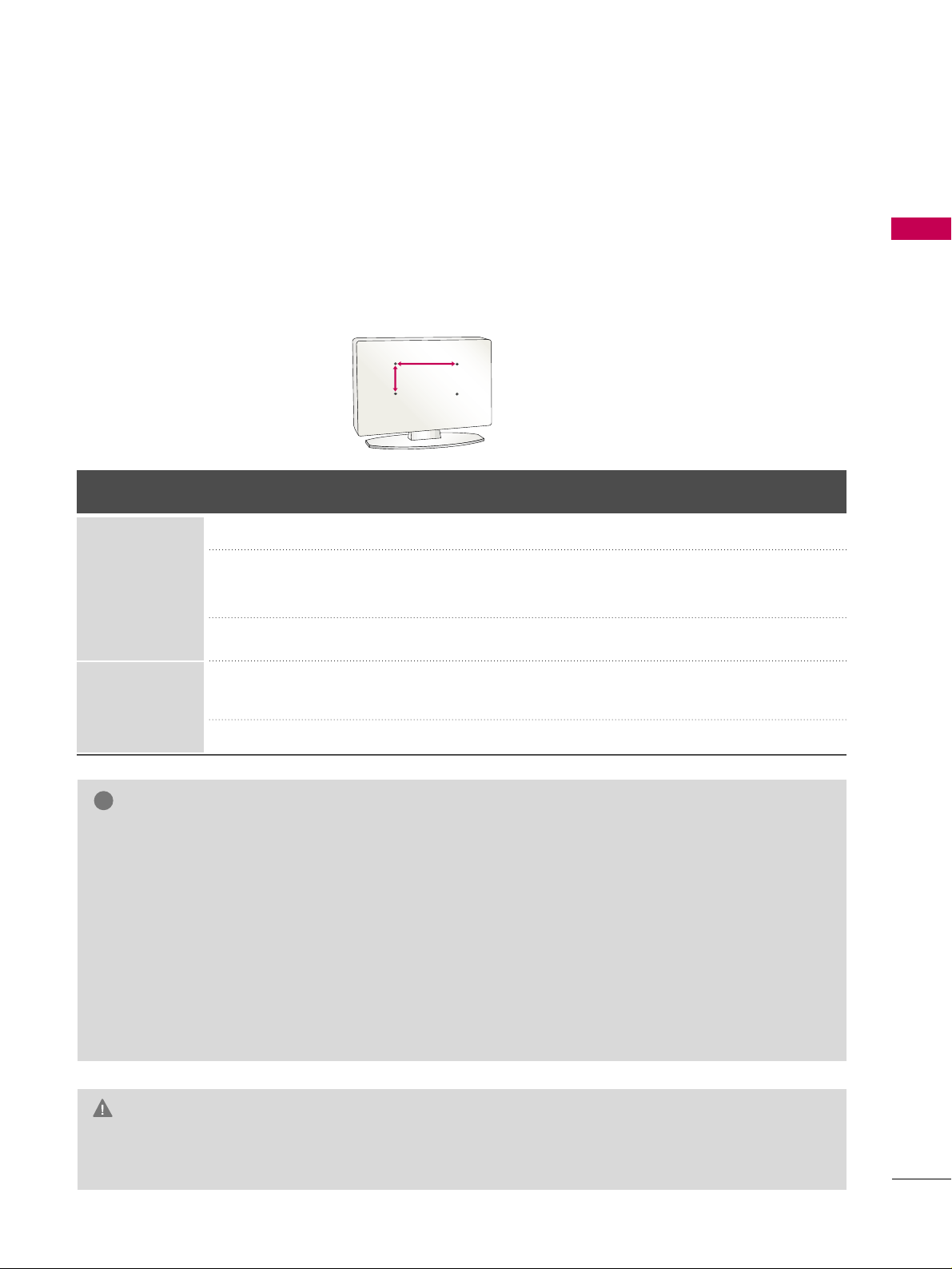
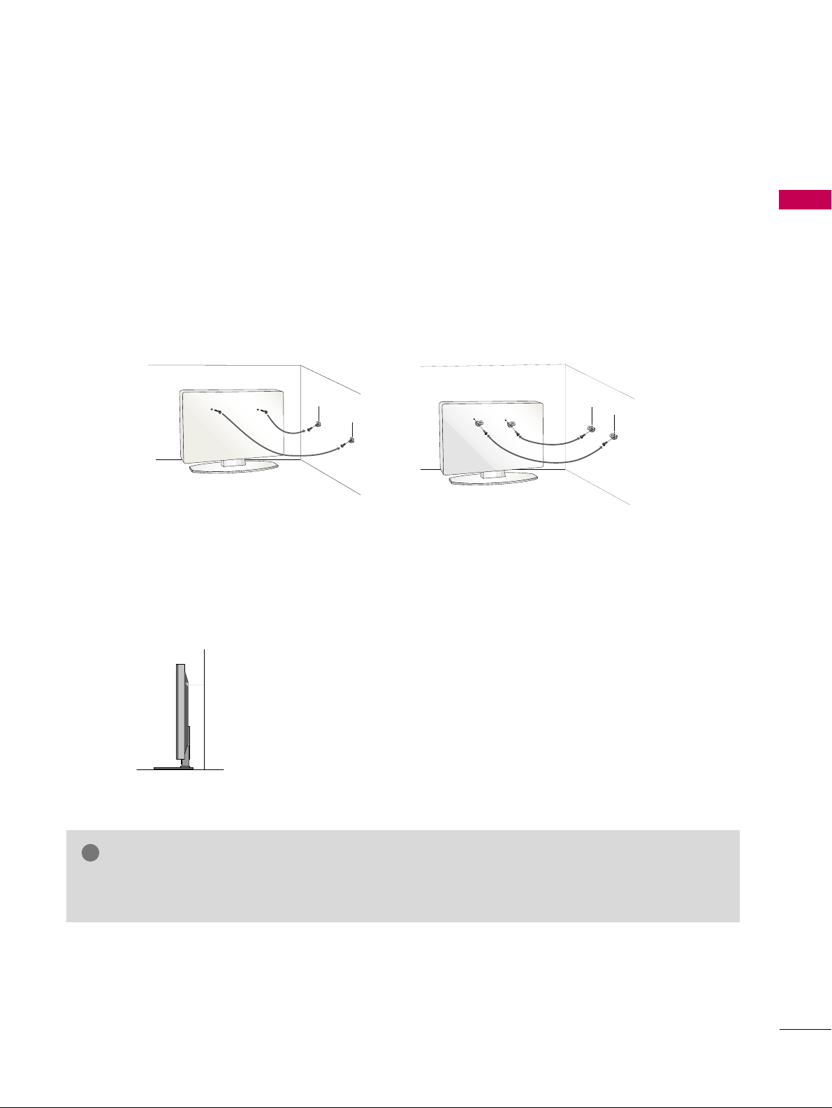
SECURING THE TV TO THE WALL TO PREVENT FALLING WHEN THE TV IS USED ON A STAND
We recommend that you set up the TV close to a wall so it cannot fall over if pushed backwards.
Additionally, we recommend that the TV be attached to a wall so it cannot be pulled in a forward direction,
potentially causing injury or damaging the product.
Caution: Please make sure that children don’t climb on or hang from the TV.
■
Insert the eye-bolts (or TV brackets and bolts) to tighten the product to the wall as shown in the picture.
*If your product has the bolts in the eye-bolts position before inserting the eye-bolts, loosen the bolts.
* Insert the eye-bolts or TV brackets/bolts and tighten them securely in the upper holes.
Secure the wall brackets with the bolts (sold separately) to the wall. Match the height of the bracket that is
mounted on the wall to the holes in the product.
Ensure the eye-bolts or brackets are tightened securely.
■
Use a sturdy rope (sold separately) to tie the product. It is safer to tie
the rope so it becomes horizontal between the wall and the product.
■
You should purchase necessary components to prevent TV from falling off of the stand.
■
Image shown may differ from your TV.
GG
Use a platform or cabinet strong enough and large enough to support the size and weight of the TV.
GG
To use the TV safely make sure that the height of the bracket on the wall and the one on the TV are the same.
NOTE
!
PREPARATION
22
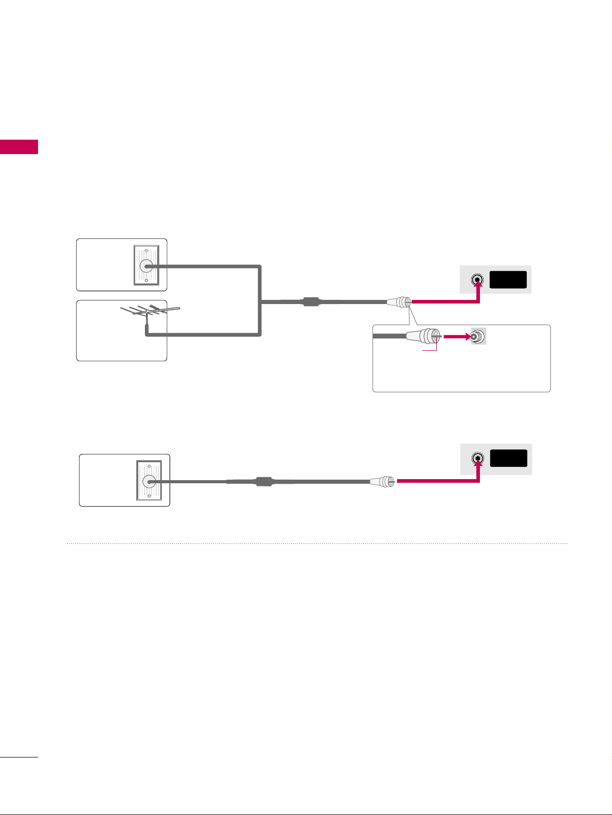
ANTENNA OR CABLE CONNECTION
PREPARATION
1. Antenna (Analog or Digital)
Wall Antenna Socket or Outdoor Antenna without a Cable Box
Connection.
For optimum picture quality, adjust the antenna direction if needed.
2. Cable
Wa ll
Antenna
Socket
Outdoor
Antenna
(VHF, UHF)
Cable TV
Wall Jack
Multi-family Dwellings/Apartments
(Connect to wall antenna socket)
RF Coaxial Wire (75 ohm)
RF Coaxial Wire (75 ohm)
Single-family Dwellings /Houses
(Connect to wall jack for outdoor antenna)
Be careful not to bend the copper wire
when connecting the antenna.
Copper Wire
■
To improve the picture quality in a poor signal area, please purchase a signal amplifier and install properly.
■
If the antenna needs to be split for two TV’s, install a 2-Way Signal Splitter.
■
If the antenna is not installed properly, contact your dealer for assistance.
ANTENNA/
CABLE IN
R
ANTENNA/
CABLE IN
R
■
To prevent damage do not connect to the power outlet until all connections are made between the devices.
EXTERNAL EQUIPMENT SETUP
23
EXTERNAL EQUIPMENT SETUP
HD RECEIVER SETUP
This TV can receive digital over-the-air/digital cable signals without an external digital set-top box. However, if
you do receive digital signals from a digital set-top box or other digital external device.
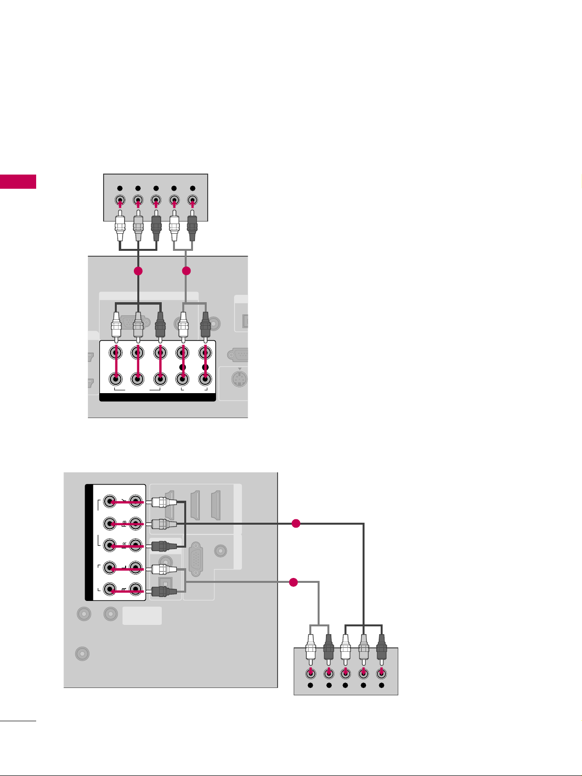
Component Connection
1. How to connect
Connect the video outputs (Y, P
B, P
R
)
of the digital set-
top box to the
CC OOMMPP OONNEENN TT II NN VVIIDDEEOO 11
jacks on
the TV. Match the jack colors (Y = green, P
B
= blue, and
P
R
= red).
Connect the audio output of the digital set-top box to
the
CC OOMMPP OONNEENN TT IINN AAUUDD IIOO 11
jacks on the TV.
2
1
2. How to use
■
Turn on the digital set-top box.
(
Refer to the owner’s manual for the digital set-top box. operation
)
■
Select the
CC oo mmppoonnee nntt 11
input source on the TV using
the
IINNPP UUTT
button on the remote control.
■
If connected to
CC OOMMPP OONN EENN TT IINN22
input, select the
CC oo mmppoonneenntt 22
input source on the TV.
■
To prevent the equipment damage, never plug in any power cords until you have finished connecting all equipment.
■
Image shown may differ from your TV.
Y, C
B/
P
B, CR/
P
R
Supported Resolutions
Horizontal Vertical
Frequency(KHz)Frequency(Hz
)
15.73 59.94
15.73 60.00
31.47 59.94
31.50 60.00
44.96 59.94
45.00 60.00
33.72 59.94
33.75 60.00
26.97 23.976
27.00 24.00
33.71 29.97
33.75 30.00
67.432 59.94
67.50 60.00
Resolution
720x480i
720x480p
1280x720p
1920x1080i
1920x1080p
Signal
480i
480p
720p
10 8 0 i
10 8 0 p
Component
Yes
Yes
Yes
Yes
Yes
HDMI
No
Yes
Yes
Yes
Yes
EXTERNAL EQUIPMENT SETUP
24
EXTERNAL EQUIPMENT SETUP
RGB IN
AUDIO
(RGB/DVI)
RGB(PC)
REMOTE
CONTROL IN
RS-232
(CONTROL &
OPT
DIGI
S-VIDEO
COMPONENT IN
1
2
VIDEO
LYP
BPR
R
AUDIO
Y L RPB PR
1
2
(RGB/DVI)
AUDIO
RGB(PC)
REMOTE
CONTROL IN
RS-232C IN
(SERVICE ONLY)
OPTICAL
COAXIAL
DIGITAL
AUDIO OUT
123
HDMI/DVI IN RGB IN
ANTENNA/
CABLE IN
COMPONENT IN
2
1
VIDEO
AUDIO
YL R PB PR
1
2
32/37/42/47/52LG60, 42LGX
Plasma TV, 32/37/42LG30, 37/42/47/52LG50,
32/42/47/52LG70, 47LG90
EXTERNAL EQUIPMENT SETUP
25
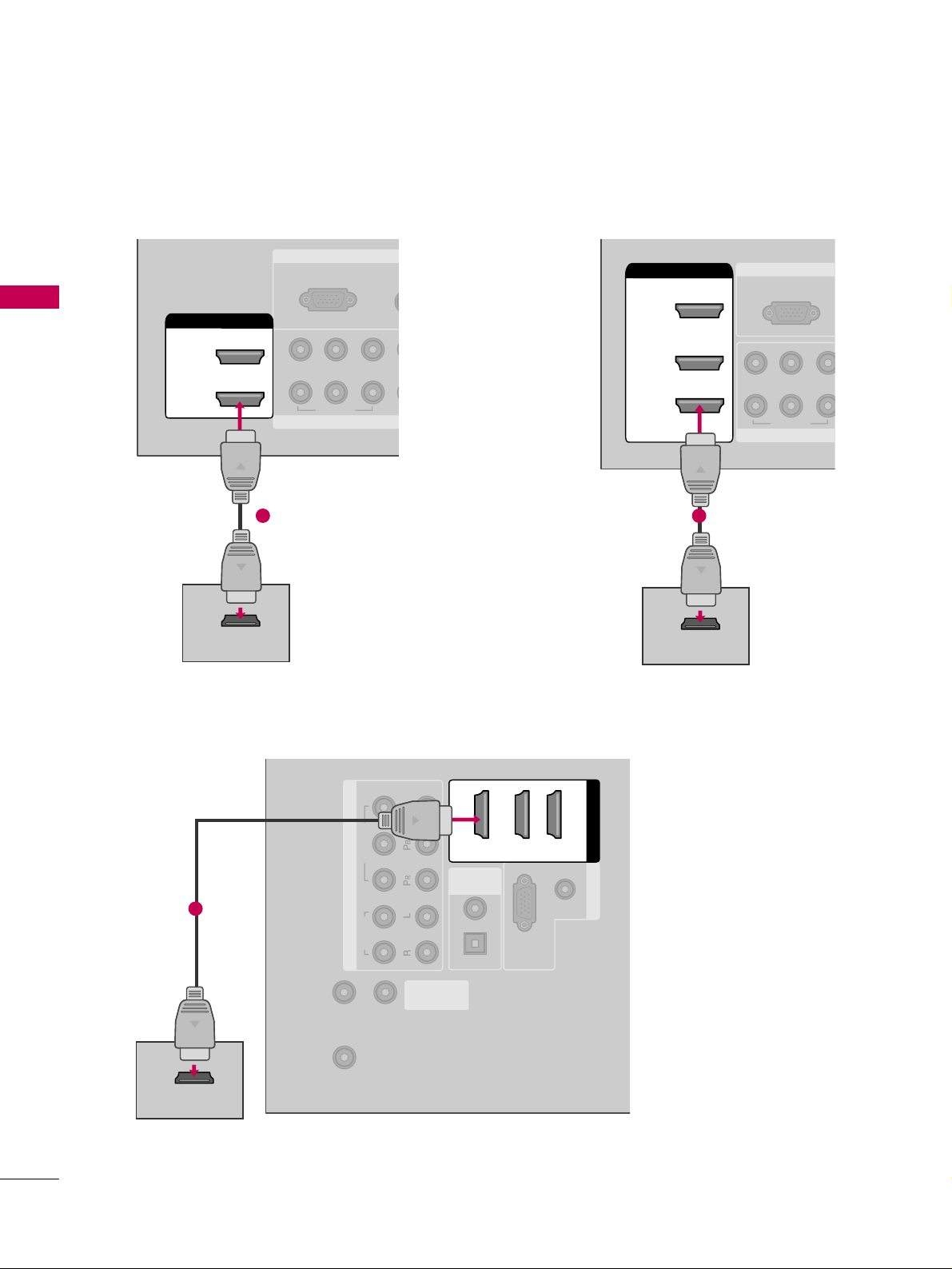
HDMI Connection
Connect the digital set-top box to
HHDDMMII//DDVVII IINN11
,
22, 33
, or
44
jack on the TV.
No separate audio connection is necessary.
HDMI supports both audio and video.
1. How to connect
2. How to use
■
Turn on the digital set-top box.
(
Refer to the owner’s manual for the digital set-top box.
)
■
Select the
HHDDMMII11, HHDDMMII22, HHDDMMII33
, or
HHDDMMII44
input
source on the TV using the
IINNPPUUTT
button on the remote
control.
2
1
HDMI-DTV
Horizontal Vertical
Frequency(KHz)Frequency(Hz
)
31.47 59.94
31.50 60.00
44.96 59.94
45.00 60.00
33.72 59.94
33.75 60.00
26.97 23.976
27.00 24.00
33.71 29.97
33.75 30.00
67.432 59.939
67.50 60.00
Resolution
720x480p
1280x720p
1920x1080i
1920x1080p
EXTERNAL EQUIPMENT SETUP
26
EXTERNAL EQUIPMENT SETUP
RGB IN
COMPONENT
A
(RG
RGB(PC)
1
2
VIDEO
YP
B
P
R
HDMI/DVI IN
2
1
HDMI-DTV OUTPUT
1
RGB IN
COMPON
RGB(PC)
VIDEO
YP
B
P
R
2
3
( )
HDMI/DVI IN
1
HDMI-DTV OUTPUT
1
(RGB/DVI)
AUDIO
RGB(PC)
REMOTE
CONTROL IN
RS-232C IN
(SERVICE ONLY)
OPTICAL
COAXIAL
DIGITAL
AUDIO OUT
RGB IN
ANTENNA/
CABLE IN
COMPONENT IN
2
1
VIDEO
AUDIO
HDMI/DVI IN
123
HDMI-DTV OUTPUT
1
32/37/42/47/52LG60, 42LGX
32/37/42LG30, 37/42/47/52LG50, 32LG70 Plasma TV, 42/47/52LG70, 47LG90
EXTERNAL EQUIPMENT SETUP
27
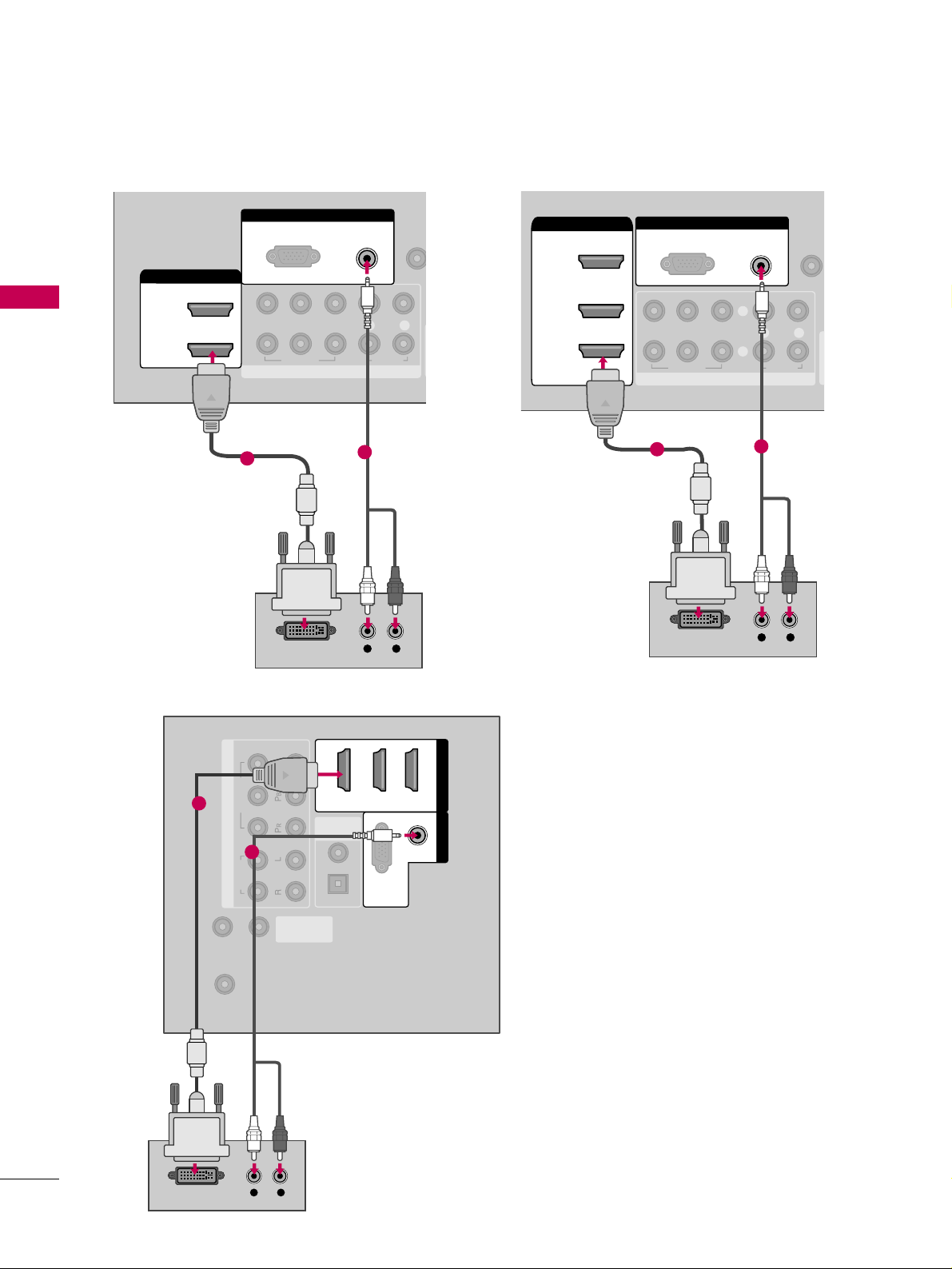
DVI to HDMI Connection
32/37/42LG30, 37/42/47/52LG50, 32LG70, Plasma TV
- Connect the DVI output of the digital set-top box to the
HHDDMM II //DD VV II IINN 11, 22
, or 33jack on the TV.
32/37/42/47/52LG60, 42/47/52LG70, 42LGX, 47LG90
- Connect the DVI output of the digital set-top box to the
HHDDMMII//DDVVII IINN 11, 22, 33
, or 44jack on the TV.
Connect the PC audio output to the
AA UUDD II OO
((
RR GGBB// DDVVII
))
jack on the TV.
1. How to connect
2. How to use
■
Turn on the digital set-top box. (Refer to the owner’s manual for the digital set-top box.
)
■
32/37/42LG30, 37/42/47/52LG50, 32LG70, Plasma TV
- Select the
HHDDMMII11,HHDDMMII22
,or
HHDDMMII33
input source on the TV using the
IINNPPUUTT
button on the remote control.
■
32/37/42/47/52LG60, 42/47/52LG70, 42LGX, 47LG90
- Select the
HHDDMMII11,HHDDMMII22,HHDDMMII33
,or
HHDDMMII44
input source on the TV using the
IINNPPUUTT
button on the remote
control.
2
1
GG
A DVI to HDMI cable or adapter is required for this connection. DVI doesn't support audio,
so a separate audio connection is necessary.
NOTE
!
EXTERNAL EQUIPMENT SETUP
28
EXTERNAL EQUIPMENT SETUP
REMOTE
CONTROL IN
RS-232C IN
(SERVICE ONLY)
OPTICAL
COAXIAL
DIGITAL
AUDIO OUT
ANTENNA/
CABLE IN
COMPONENT IN
2
1
VIDEO
AUDIO
HDMI/DVI IN
123
(RGB/DVI)
AUDIO
RGB(PC)
RGB IN
L R
DVI-DTV OUTPUT
1
2
32/37/42/47/52LG60, 42LGX
RGB IN
COMPONENT IN
AUDIO
(RGB/DVI)
RGB(PC)
REMO
CONTRO
1
2
VIDEO
LYP
BPR
R
AUDIO
HDMI/DVI IN
2
1
L R
DVI-DTV OUTPUT
1
2
32/37/42LG30, 37/42/47/52LG50, 32LG70
( )
RGB IN
COMPONENT IN
AUDIO
(RGB/DVI)
RGB(PC)
REMOT
CONTROL
(
VIDEO
LYP
BPR
R
AUDIO
AV IN 1
2
3
2
1
( )
HDMI/DVI IN
1
L R
DVI-DTV OUTPUT
1
Plasma TV, 42/47/52LG70, 47LG90
2
 Loading...