

LG 37LG700HUA, 42LG700HUA User Manual

Please read this manual carefully before operating
your set.
Retain it for future reference.
Record model number and serial number of the set.
See the label attached on the back cover and quote
this information to your dealer
when you require service.
LCD TV
OWNER’S MANUAL
32LG700H
37LG700H
42LG700H
Inst
aller Reference for Commercial Mode
MPI/PPV Card Setup see page 19
Commercial Mode Setup see pages 87-104
P/NO : SAC30708043 (0810-REV00)
www.lgcommercial.com
This product qualifies for ENERGY STAR in the “factory default
(Home mode)” setting and this is the setting in which power
savings will be achieved.
Changing the factory default picture setting or enabling other
features will increase power consumption that could exceed the
limits necessary to quality for Energy Star rating.

1
WARNING / CAUTION
WARNING / CAUTION
To prevent fire or shock hazards, do not expose
this product to rain or moisture.
FCC NOTICE
Class B digital device
This equipment has been tested and found to comply
with the limits for a Class B digital device, pursuant to
Part 15 of the FCC Rules. These limits are designed
to provide reasonable protection against harmful
interference in a residential installation. This equipment
generates, uses and can radiate radio frequency energy
and, if not installed and used in accordance with the
instructions, may cause harmful interference to radio
communications. However, there is no guarantee that
interference will not occur in a particular installation.
If this equipment does cause harmful interference to
radio or television reception, which can be determined
by turning the equipment off and on, the user is
encouraged to try to correct the interference by one
or more of the following measures:
- Reorient or relocate the receiving antenna.
- Increase the separation between the equipment and
receiver.
- Connect the equipment to an outlet on a circuit
different from that to which the receiver is connected.
- Consult the dealer or an experienced radio/TV
technician for help.
Any changes or modifications not expressly approved
by the party responsible for compliance could void
the user’s authority to operate the equipment.
CAUTION
Do not attempt to modify this product in any way
without written authorization from LG Electronics.
Unauthorized modification could void the user’s
authority to operate this product
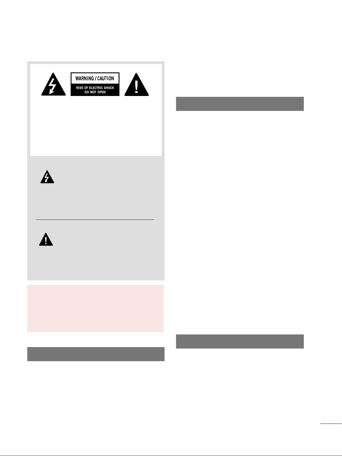
The lightning flash with arrowhead
symbol, within an equilateral triangle, is
intended to alert the user to the presence
of uninsulated “dangerous voltage” within the
product’s enclosure that may be of sufficient
magnitude to constitute a risk of electric shock to
persons.
The exclamation point within an equilateral
triangle is intended to alert the user to
the presence of important operating and
maintenance (servicing) instructions in the literature accompanying the appliance.
TO REDUCE THE RISK OF ELECTRIC SHOCK
DO NOT REMOVE COVER (OR BACK). NO
USER SERVICEABLE PARTS INSIDE. REFER TO
QUALIFIED SERVICE PERSONNEL.
WARNING/CAUTION
TO REDUCE THE RISK OF FIRE AND ELECTRIC
SHOCK, DO NOT EXPOSE THIS PRODUCT TO
RAIN OR MOISTURE.
NOTE TO CABLE/TV INSTALLER
This reminder is provided to call the CATV system
installer’s attention to Article 820-40 of the National
Electric Code (U.S.A.). The code provides guidelines for
proper grounding and, in particular, specifies that the
cable ground shall be connected to the grounding system
of the building, as close to the point of the cable entry
as practical.
Read these instructions.
Keep these instructions.
Heed all warnings.
Follow all instructions.
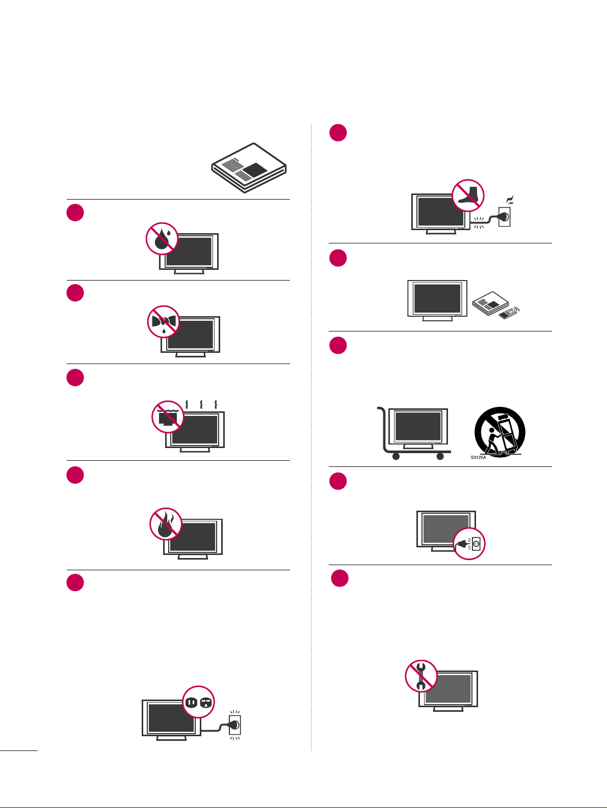
Do not use this apparatus near water.
Clean only with dry cloth.
Do not block any ventilation openings. Install in
accordance with the manufacturer’s instructions.
Do not install near any heat sources such as
radiators, heat registers, stoves, or other apparatus
(including amplifiers)that produce heat.
Do not defeat the safety purpose of the polarized
or grounding-type plug. A polarized plug has
two blades with one wider than the other. A
grounding type plug has two blades and a third
grounding prong, The wide blade or the third
prong are provided for your safety. If the provided
plug does not fit into your outlet, consult an
electrician for replacement of the obsolete outlet.
Protect the power cord from being walked on
or pinched particularly at plugs, convenience
receptacles, and the point where they exit from
the apparatus.
Only use attachments/accessories specified by
the manufacturer.
Use only with the cart, stand, tripod, bracket,
or table specified by the manufacturer, or sold
with the apparatus. When a cart is used, use
caution when moving the cart/apparatus
combination to avoid injury from tip-over.
Unplug this apparatus during lighting storms or
when unused for long periods of time.
Refer all servicing to qualified service personnel.
Servicing is required when the apparatus has been
damaged in any way, such as power-supply cord or
plug is damaged, liquid has been spilled or objects
have fallen into the apparatus, the apparatus has
been exposed to rain or moisture, does not operate
normally, or has been dropped.
2
IMPORTANT SAFETY INSTRUCTIONS
SAFETY INSTRUCTIONS
1
2
3
4
5
7
8
6
9
10
3
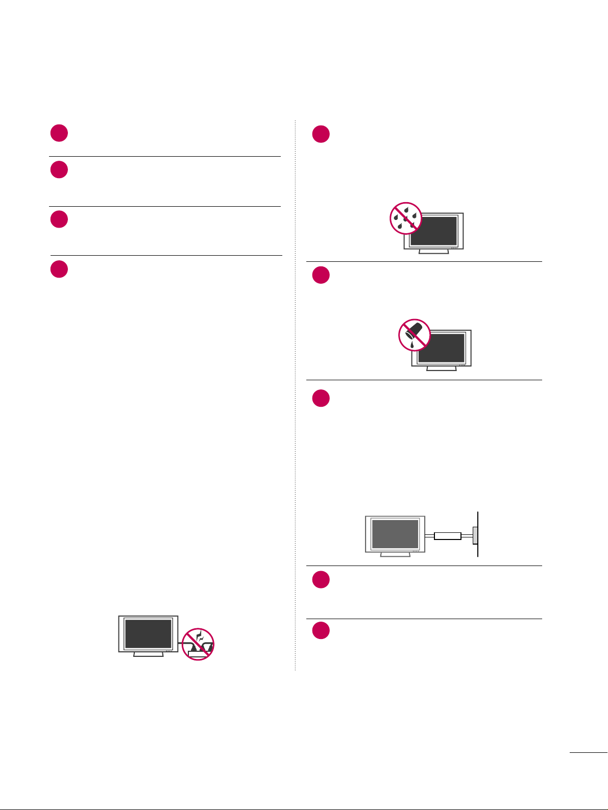
Never touch this apparatus or antenna during a
thunder or lighting storm.
When mounting a TV on the wall, make sure not to
install the TV by the hanging power and signal
cables on the back of the TV.
Do not allow an impact shock or any objects to fall
into the product, and do not drop onto the screen
with something.
CAUTION concerning the Power Cord :
It is recommend that appliances be placed upon a
dedicated circuit; that is, a single outlet circuit which
powers only that appliance and has no additional
outlets or branch circuits. Check the specification
page of this owner's manual to be certain.
Do not connect too many appliances to the same
AC power outlet as this could result in fire or electric shock.
Do not overload wall outlets. Overloaded wall outlets, loose or damaged wall outlets, extension cords,
frayed power cords, or damaged or cracked wire
insulation are dangerous. Any of these conditions
could result in electric shock or fire. Periodically
examine the cord of your appliance, and if its
appearance indicates damage or deterioration,
unplug it, discontinue use of the appliance, and
have the cord replaced with an exact replacement
part by an authorized servicer. Protect the power
cord from physical or mechanical abuse, such as
being twisted, kinked, pinched, closed in a door, or
walked upon. Pay particular attention to plugs, wall
outlets, and the point where the cord exits the
appliance.
Do not make the TV with the power cord plugged
in. Do not use a damaged or loose power cord. Be
sure do grasp the plug when unplugging the power
cord. Do not pull on the power cord to unplug the
TV.
WARNING - To reduce the risk of fire or electrical
shock, do not expose this product to rain, moisture
or other liquids. Do not touch the TV with wet
hands. Do not install this product near flammable
objects such as gasoline or candles or expose the
TV to direct air conditioning.
Do not expose to dripping or splashing and do not
place objects filled with liquids, such as vases, cups,
etc. on or over the apparatus (e.g. on shelves above
the unit).
GGRROOUUNNDDIINNGG
Ensure that you connect the earth ground wire to
prevent possible electric shock. (i.e. a TV with a
three-prong grounded AC plug must be connected
to a three-prong grouned AC outlet) If grounding
methods are not possible, have a qualified electrician install a separate circuit breaker.
Do not try to ground the unit by connecting it to
telephone wires, lightening rods, or gas pipes.
DDIISSCCOONNNNEECCTTIINNGG DDEEVVIICCEE FFRROOMM MMAAIINNSS
Mains plug is the disconnecting device. The plug
must remain readily operable.
Keep the product away from direct sunlight.
12
11
14
13
16
17
18
19
Power
Supply
Short-circuit
Breaker
15
4
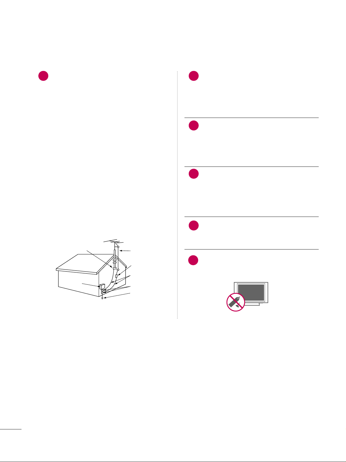
AANNTTEENNNNAASS
OOuuttddoooorr aanntteennnnaa ggrroouunnddiinngg
If an outdoor antenna is installed, follow the precautions below. An outdoor antenna system should not
be located in the vicinity of overhead power lines or
other electric light or power circuits, or where it can
come in contact with such power lines or circuits as
death or serious injury can occur.
Be sure the antenna system is grounded so as to provide some protection against voltage surges and
built-up static charges.
Section 810 of the National Electrical Code (NEC) in
the U.S.A. provides information with respect to proper grounding of the mast and supporting structure,
grounding of the lead-in wire to an antenna discharge unit, size of grounding conductors, location of
antenna discharge unit, connection to grounding
electrodes and requirements for the grounding electrode.
AAnntteennnnaa ggrroouunnddiinngg aaccccoorrddiinngg ttoo tthhee
NNaattiioonnaall EElleeccttrriiccaall CCooddee,, AANNSSII//NNFFPPAA 7700
Cleaning
When cleaning, unplug the power cord and scrub
gently with a soft cloth to prevent scratching. Do not
spray water or other liquids directly on the TV as
electric shock may occur. Do not clean with chemicals such as alcohol, thinners or benzene.
Moving
Make sure the product is turned off, unplugged
and all cables have been removed. It may take 2 or
more people to carry larger TVs. Do not press
against or put stress on the front panel of the TV.
Ventilation
Install your TV where there is proper ventilation. Do
not install in a confined space such as a bookcase.
Do not cover the product with cloth or other materials (e.g.) plastic while plugged in. Do not install in
excessively dusty places.
If you smell smoke or other odors coming from the
TV or hear strange sounds, unplug the power cord
contact an authorized service center.
Do not press strongly upon the panel with a hand or
sharp object such as nail, pencil or pen, or make a
scratch on it.
22
20
Antenna Lead in Wire
Antenna Discharge Unit
(NEC Section 810-20)
Grounding Conductors
(NEC Section 810-21)
Ground Clamps
Power Service Grounding
Electrode System (NEC
Art 250, Part H)
Ground Clamp
Electric Service
Equipment
NEC: National Electrical Code
23
24
21
25

5
CONTENTS
WARNING / CAUTION
. . . . . . . . . . . . . . . . . . . . . . . . . . . . 1
SAFETY INSTRUCTIONS
. . . . . . . . . . . . . . . . . . . . . . . . . .
2
FEATURES OF THIS TV
. . . . . . . . . . . . . . . . . . . . . . . . . . . . . 7
PREPARATION
Accessories
. . . . . . . . . . . . . . . . . . . . . . . . . . . . . . . . . . . . . . . . . . . . . . . . . . . . . . 8
Front Panel Information
. . . . . . . . . . . . . . . . . . . . . . . . . . . . . . . . . . . . . 9
Back Panel Information
. . . . . . . . . . . . . . . . . . . . . . . . . . . . . . . . . . . . 10
Stand Instruction
. . . . . . . . . . . . . . . . . . . . . . . . . . . . . . . . . . . . . . . . . . . . .12
Cable Management
. . . . . . . . . . . . . . . . . . . . . . . . . . . . . . . . . . . . . . . . .13
Desktop Pedestal Installation
. . . . . . . . . . . . . . . . . . . . . . . . . . . . 14
Swivel Stand
. . . . . . . . . . . . . . . . . . . . . . . . . . . . . . . . . . . . . . . . . . . . . . . . . . . . 14
Attaching the TV to a desk
. . . . . . . . . . . . . . . . . . . . . . . . . . . . . . . 15
VESA Wall Mounting
. . . . . . . . . . . . . . . . . . . . . . . . . . . . . . . . . . . . . . . .
16
Securing the TV to the wall to prevent falling
When the TV is used on a stand
. . . . . . . . . . . . . . . . . . . . . . . . . . 17
Antenna or Cable Connection
. . . . . . . . . . . . . . . . . . . . . . . . . . 18
MPI Card Slot / PPV Card Installation
. . . . . . . . . . . . . . . 19
EXTERNAL EQUIPMENT SETUP
HD Receiver Setup
- Component Connection
. . . . . . . . . . . . . . . . . . . . . . . . . . . 20
- HDMI Connection
. . . . . . . . . . . . . . . . . . . . . . . . . . . . . . . . . . . . . 21
- DVI to HDMI Connection
. . . . . . . . . . . . . . . . . . . . . . . . . . 22
DVD Setup
- Component Connection
. . . . . . . . . . . . . . . . . . . . . . . . . . . . 23
- HDMI Connection
. . . . . . . . . . . . . . . . . . . . . . . . . . . . . . . . . . . . 24
VCR Setup
- Antenna Connection
. . . . . . . . . . . . . . . . . . . . . . . . . . . . . . . . . 25
- Composite (RCA) Connection
. . . . . . . . . . . . . . . . . . . 25
Other A/V Source Setup
. . . . . . . . . . . . . . . . . . . . . . . . . . . . . . . . . 26
PC Setup
- VGA (D-Sub 15 pin) Connection
. . . . . . . . . . . . . . . 27
- DVI to HDMI Connection
. . . . . . . . . . . . . . . . . . . . . . . . . . 28
- Screen Setup for PC mode
. . . . . . . . . . . . . . . . . . . . . . . . 29
Audio Out Connection
. . . . . . . . . . . . . . . . . . . . . . . . . . . . . . . . . . . . 33
WATCHING TV / CHANNEL CONTROL
Remote Control Functions . . . . . . . . . . . . . . . . . . . . . . . . . . . . . . . 34
Turning On TV
. . . . . . . . . . . . . . . . . . . . . . . . . . . . . . . . . . . . . . . . . . . . . . . . 36
Channel Selection
. . . . . . . . . . . . . . . . . . . . . . . . . . . . . . . . . . . . . . . . . . . 37
Volume Adjustment
. . . . . . . . . . . . . . . . . . . . . . . . . . . . . . . . . . . . . . . . .37
On-Screen Menus Selection
. . . . . . . . . . . . . . . . . . . . . . . . . . . . . 38
Channel Setup
- Auto Scan (Auto Tuning)
. . . . . . . . . . . . . . . . . . . . . . . . . . . 39
- Add / Delete Channel (Manual Tuning)
. . . . . . 40
- Channel Editing
. . . . . . . . . . . . . . . . . . . . . . . . . . . . . . . . . . . . . . . . 41
Channel Label
. . . . . . . . . . . . . . . . . . . . . . . . . . . . . . . . . . . . . . . . . . . . . . . . . 42
Input List
. . . . . . . . . . . . . . . . . . . . . . . . . . . . . . . . . . . . . . . . . . . . . . . . . . . . . . . . 43
PICTURE CONTROL
Picture Size (Aspect Ratio) Control
. . . . . . . . . . . . . . . . . . 44
Preset Picture Settings
- Picture Mode - Preset
. . . . . . . . . . . . . . . . . . . . . . . . . . . . . . . 47
- Color Tone - Preset
. . . . . . . . . . . . . . . . . . . . . . . . . . . . . . . . . . 48
Manual Picture Adjustment
- Picture Mode - User Mode
. . . . . . . . . . . . . . . . . . . . . . . . 49
Picture Improvement Technology
. . . . . . . . . . . . . . . . . . . . . 50
Advanced Control - Black (Darkness) Level
. . . . . . . 51
Eye Care
. . . . . . . . . . . . . . . . . . . . . . . . . . . . . . . . . . . . . . . . . . . . . . . . . . . . . . . . .52
Advanced Control -
Film Mode . . . . . . . . . . . . . . . . . . . . . . . . .53
Picture Reset
. . . . . . . . . . . . . . . . . . . . . . . . . . . . . . . . . . . . . . . . . . . . . . . . . 54
SOUND & LANGUAGE CONTROL
Auto Volume Leveler (Auto Volume) . . . . . . . . . . . . . . . . . 55
Preset Sound Settings (Sound Mode)
. . . . . . . . . . . . . . 56
Sound Setting Adjustment - User Mode
. . . . . . . . . . . 57
- SRS TruSurround XT
. . . . . . . . . . . . . . . . . . . . . . . . . . . . . . . . . 58
Clear Voice
. . . . . . . . . . . . . . . . . . . . . . . . . . . . . . . . . . . . . . . . . . . . . . . . . . . . . 59
Balance
. . . . . . . . . . . . . . . . . . . . . . . . . . . . . . . . . . . . . . . . . . . . . . . . . . . . . . . . . .60
TV Speakers On/Off Setup
. . . . . . . . . . . . . . . . . . . . . . . . . . . . . . 61
Audio Reset
. . . . . . . . . . . . . . . . . . . . . . . . . . . . . . . . . . . . . . . . . . . . . . . . . . . 62
Stereo/SAP Broadcast Setup
. . . . . . . . . . . . . . . . . . . . . . . . . . . 63
Audio Language
. . . . . . . . . . . . . . . . . . . . . . . . . . . . . . . . . . . . . . . . . . . . . . 64
On-Screen Menus Language Selection
. . . . . . . . . . . . . 65
Caption Mode
- Analog Broadcasting System Captions
. . . . . . . 66
- Digital Broadcasting System Captions
. . . . . . . . 67
- Caption Option
. . . . . . . . . . . . . . . . . . . . . . . . . . . . . . . . . . . . . . . 68
TIME SETTING
Clock Setting
- Auto Clock Setup
. . . . . . . . . . . . . . . . . . . . . . . . . . . . . . . . . . . . 69
- Manual Clock Setup
. . . . . . . . . . . . . . . . . . . . . . . . . . . . . . . . . 70
Auto On/Off Time Setting
. . . . . . . . . . . . . . . . . . . . . . . . . . . . . . 71
Sleep Timer Setting
. . . . . . . . . . . . . . . . . . . . . . . . . . . . . . . . . . . . . . . . .72
Auto Shut-off Setting
. . . . . . . . . . . . . . . . . . . . . . . . . . . . . . . . . . . . . . . 73

6
PARENTAL CONTROL / RATINGS
Set Password & Lock System . . . . . . . . . . . . . . . . . . . . . . . . . . . 74
Channel Blocking
. . . . . . . . . . . . . . . . . . . . . . . . . . . . . . . . . . . . . . . . . . . . 77
Movie & TV Rating
. . . . . . . . . . . . . . . . . . . . . . . . . . . . . . . . . . . . . . . . . . 78
Downloadable Rating
. . . . . . . . . . . . . . . . . . . . . . . . . . . . . . . . . . . . . . . 81
External Input Blocking
. . . . . . . . . . . . . . . . . . . . . . . . . . . . . . . . . . . . 82
Example Electronic Program Guide
. . . . . . . . . . . . . . . . . . . 83
Interactive TV Setup
. . . . . . . . . . . . . . . . . . . . . . . . . . . . . . . . . . . . . . . . 84
PIP (Picture-In-Picture)
. . . . . . . . . . . . . . . . . . . . . . . . . . . . . . . . . . . . 85
COMMERCIAL MODE SETUP
Installer Overview . . . . . . . . . . . . . . . . . . . . . . . . . . . . . . . . . . . . . . . . . . . .87
Interactive TV Overview
. . . . . . . . . . . . . . . . . . . . . . . . . . . . . . . . . . . 88
Commercial Mode Setup for Master TV
. . . . . . . . . . . . 89
TLL-1100A Cloning Connections/Learning Setup
. . . . . . . . . . . . . . . . . . . . . . . . . . . . . . . . . . . . . . . . . . . . . . . . . . . . . . . . . . . . . . . . . . . . . .
90
LT2002 Cloning Connections/Learning Setup
. . 91
LT2002 Cloning Learning Setup
. . . . . . . . . . . . . . . . . . . . . . 92
Cloning Connections/Teaching Setup
. . . . . . . . . . . . . . 93
Installer Menu
. . . . . . . . . . . . . . . . . . . . . . . . . . . . . . . . . . . . . . . . . . . . . . . . . 94
Reference: Detailed Instructions For Making A
Master TV
. . . . . . . . . . . . . . . . . . . . . . . . . . . . . . . . . . . . . . . . . . . . . . . . . . . . .
10 0
Reference: Procedures for adding Channel Label
Icons/Custom Channel Labels (2-5-4 + MENU
Mode)
. . . . . . . . . . . . . . . . . . . . . . . . . . . . . . . . . . . . . . . . . . . . . . . . . . . . . . . . . .101
Reference: Clonable Menu Features
. . . . . . . . . . . . . . . . 10 2
Reference: Power Saving Setup
. . . . . . . . . . . . . . . . . . . . . . .10 3
TV Aux Input Configuration
. . . . . . . . . . . . . . . . . . . . . . . . . . . 10 3
TV Camport Auto Sense Operation
. . . . . . . . . . . . . . . . 10 4
APPENDIX
Troubleshooting . . . . . . . . . . . . . . . . . . . . . . . . . . . . . . . . . . . . . . . . . . . . 10 5
Reference: LT2002 Cloning Procedure
Troubleshooting
. . . . . . . . . . . . . . . . . . . . . . . . . . . . . . . . . . . . . . . . . . . . 10 7
Troubleshooting Flow Chart
. . . . . . . . . . . . . . . . . . . . . . . . . . . 10 8
Commercial Mode Check
. . . . . . . . . . . . . . . . . . . . . . . . . . . . . . . 10 9
Glossary of Terms
. . . . . . . . . . . . . . . . . . . . . . . . . . . . . . . . . . . . . . . . . . 110
Maintenance
. . . . . . . . . . . . . . . . . . . . . . . . . . . . . . . . . . . . . . . . . . . . . . . . . .111
Product Specifications
. . . . . . . . . . . . . . . . . . . . . . . . . . . . . . . . . . . . 111
Programming the Remote Control
. . . . . . . . . . . . . . . . . . . 112
IR Codes
. . . . . . . . . . . . . . . . . . . . . . . . . . . . . . . . . . . . . . . . . . . . . . . . . . . . . . . 115
7
FEATURES OF THIS TV
is a trademark of SRS Labs, Inc.
TruSurround XT technology is incorporated under
license from SRS Labs, Inc.
Manufactured under license from Dolby Laboratories.
“
Dolby
“and the double-D symbol are trademarks of
Dolby Laboratories.
USB IN
SERVUCE ONLYSERVUCE ONLY
USB port shall be used for software update by service
personnel only.
FOR LCD TV
■
If the TV feels cold to the touch, there may be a small “flicker” when it is turned on. This is normal, there is nothing wrong
with TV.
■
Some minute dot defects may be visible on the screen, appearing as tiny red, green, or blue spots. However, they have no adverse
effect on the monitor's performance.
■
Avoid touching the LCD screen or holding your finger(s) against it for long periods of time. Doing so may produce some
temporary distortion effects on the screen.
On Disposal
The fluorescent lamp used in this product contains a small amount of mercury. Do not dispose of this product with general
household waste. Disposal of this product must be carried out in accordance to the regulations of your local authority.
HDMITM, the HDMI logo and High-Definition
Multimedia Interface are trademarks or registered
trademarks of HDMI Licensing."
8
PREPERATION
ACCESSORIES
Ensure that the following accessories are included with your TV. If an accessory is missing, please contact the
dealer where you purchased the TV.
The accessories included may differ from the images below.
Copyright© 2007 LGE,
All Rights Reserved.
Owner’s Manual
Power Cord
CD Manual
Protective Bracket and
Bolt for Power Cord
(Refer to P.13)
Cable Holder
(Refer to P.13)
* Wipe spots on the exterior only with the pol-
ishing cloth.
* Do not wipe roughly when removing stains.
Excessive pressure may cause scratches or
discoloration.
Polishing Cloth
(This feature is not avail-
able for all models.)
OOppttiioonn EExxttrraass
D-sub 15 pin Cable
When using the VGA (D-sub 15 pin
cable) PC connection, the user
must use shielded signal interface
cables with ferrite cores to maintain
standards compliance.
x 2
Torx plus
Star head screw
(Refer to P.12)
M4xL22
(Machine Screw)
Screw for stand fixing
(Refer to P.15)
Ø
4xL20
(Plastic Screw)
Bolts for stand assembly
(Refer to P.12)
x 4 x 4
M4xL26
(Machine Screw)
Ø
4xL20
(Plastic Screw)
PREPARATION
9
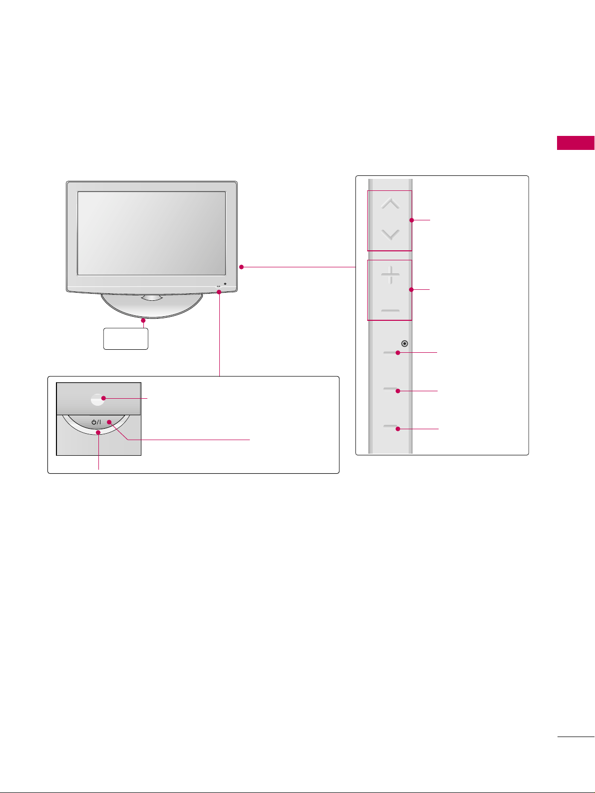
FRONT PANEL INFORMATION
■
Image shown may differ from your TV.
■
NOTE: If your TV has a protection tape attached, remove the tape.
And then wipe the TV with a cloth (If a polishing cloth is included with your TV, use it).
POWER Button
Power/Standby Indicator
Illuminates red in standby mode.
Illuminates blue when the set is switched on.
VOLUME (+, -)
Buttons
ENTER Button
MENU Button
INPUT Button
Remote Control Sensor
CHANNEL(+, -)
Buttons
Stand
CH
VOL
ENTER
MENU
INPUT
PREPARATION
10
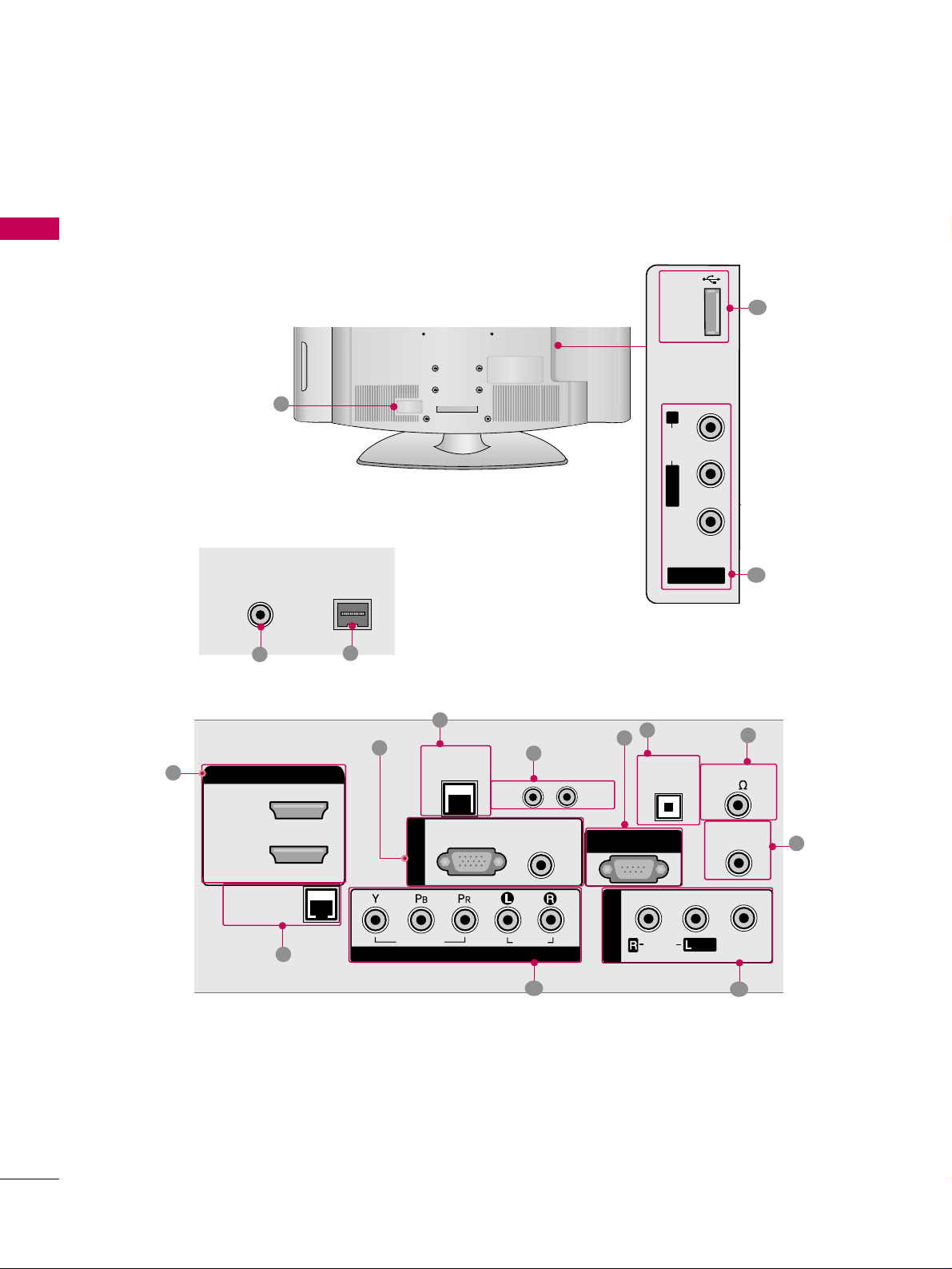
PREPARATION
■
Image shown may differ from your TV.
BACK PANEL INFORMATION
R
8
2
4
R
ANTENNA IN
M.P.I.
7
1
3
5
6
9
10
11
12
13
15
14
11
USB
SERVICE ONLY
ANTENNA IN
HDMI/DVI IN
2
1(DVI)
M.P.I.
LAN
(SERVICE ONLY)
RGB(PC)
RESET
AUDIO
(RGB/DVI)
UPDATE
RS-232C IN
(SERVICE ONLY)
R
AUDIO
L/ MONO
VIDEO
AV I N 2
OPTICAL
DIGITAL
AUDIO OUT
SPEAKER OUT
8
REMOTE
CONTROL OUT
RGB IN
RJP
INTERFACE
VIDEO
COMPONENT IN
AUDIO
AV IN 1
AUDIO
MONO
/
VIDEO

PREPARATION
11
REMOTE CONTROL OUT
IR output for controlling an auxiliary device.
RJP INTERFACE (REMOTE JACK PACK PORT)
Connect to remote jack pack control output port.
COMPONENT IN
Analog Connection.
Supports HD.
Uses a red, green, and blue cable for video & a red
and white cable for audio.
AV (Audio/Video) IN
Analog composite connection. Supports standard
definition video only (480i).
Used for PC/DTV audio input jack.
USB SERVICE ONLY
Used for software updates.
ANTENNA IN
Connect over-the air signals to this jack.
M.P. I.
Power Cord Socket
For operation with AC power.
Caution: Never attempt to operate the TV on DC
power.
HDMI/DVI IN
Digital Connection. Supports HD video and Digital
audio.
Accepts DVI video using an adapter or HDMI to
DVI cable (not included)
LAN (SERVICE ONLY)
Connect to control network.
UPDATE
Software downloads and debug mode enable/disable.
RESET
Hardware reset to PTC microcontroller.
OPTICAL DIGITAL AUDIO OUT
Digital audio output for use with amps and home
theater systems.
Includes an optical connection.
Note: In standby mode, these ports do not work.
SPEAKER OUT 8
Ω
Connect to external speaker input.
RGB IN (PC)
Analog PC Connection. Uses a D-sub 15 pin cable
(VGA cable).
AUDIO (RGB/DVI)
1/8” headphone jack for analog PC audio input.
RS-232C IN (SERVICE ONLY)
Used for software updates.
1
2
3
4
5
9
8
6
7
10
11
12
13
14
15
PREPARATION
12
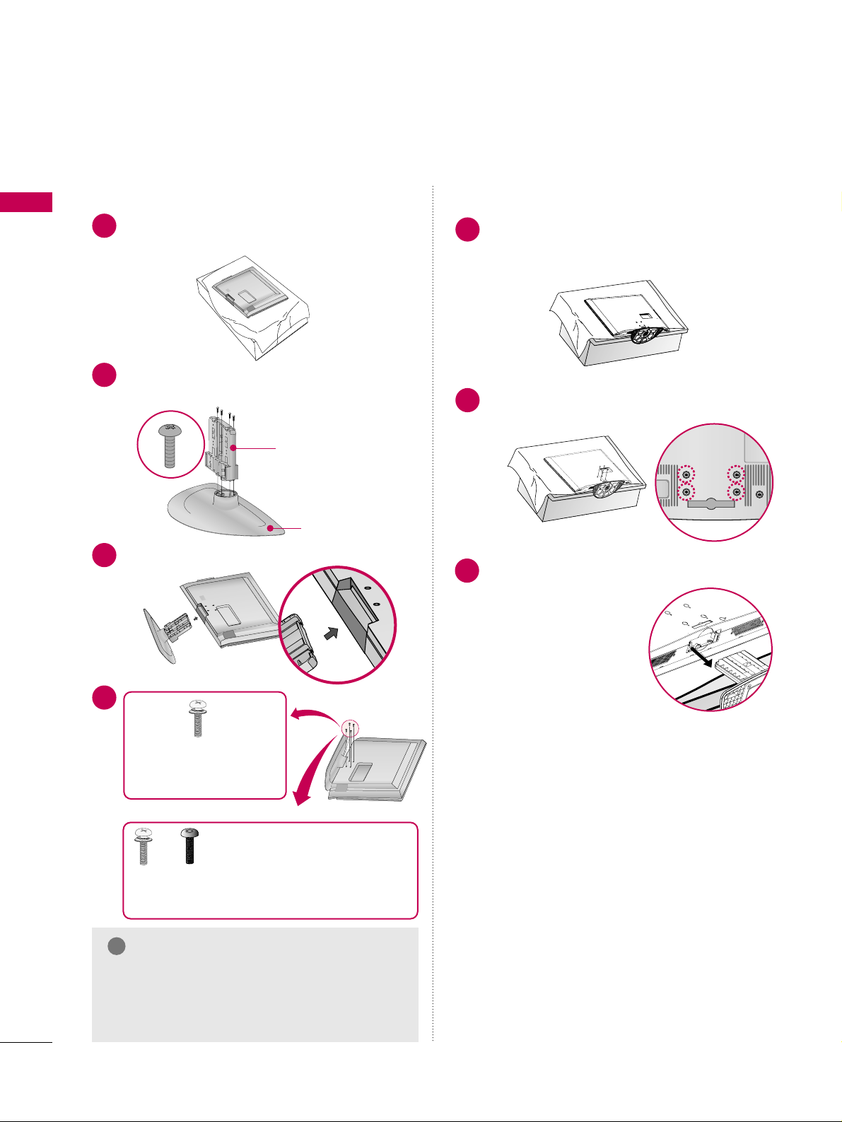
STAND INSTRUCTION
PREPARATION
Carefully place the TV screen side down on a
cushioned surface to protect the screen from
damage.
Assemble the parts of the
SSTTAA NN DD BB OODDYY
with
CCOOVVEE RR BB AASSEE
of the TV.
1
2
Insert the stand as shown.
3
SSTTAA NNDD BB OODD YY
CCOOVVEE RR BB AASSEE
■
Image shown may differ from your TV.
GG
Make sure the screws in the stand are fully
tightened. (If not tightened fully, the product
could tilt forward and fall). But do not over
tighten, over-tightening can damage the threads
on the screws.
NOTE
!
DETACHMENT
Carefully place the TV screen side down on a
cushioned surface to protect the screen from
damage.
1
Remove the four screws that hold the base on.
2
Detach the stand from TV.
3
INSTALLATION
4
or
x 4
Tighten the stand with the
four screws (provided as parts
of the TV).
Tighten the two of these four screws
and the two Torx plus star head screws
(provided as parts of the TV) to secure the TV. Tighten
the two Torx plus star head screws with a star head driver bit (not provided as parts of the TV).
x 2
x 2
PREPARATION
13
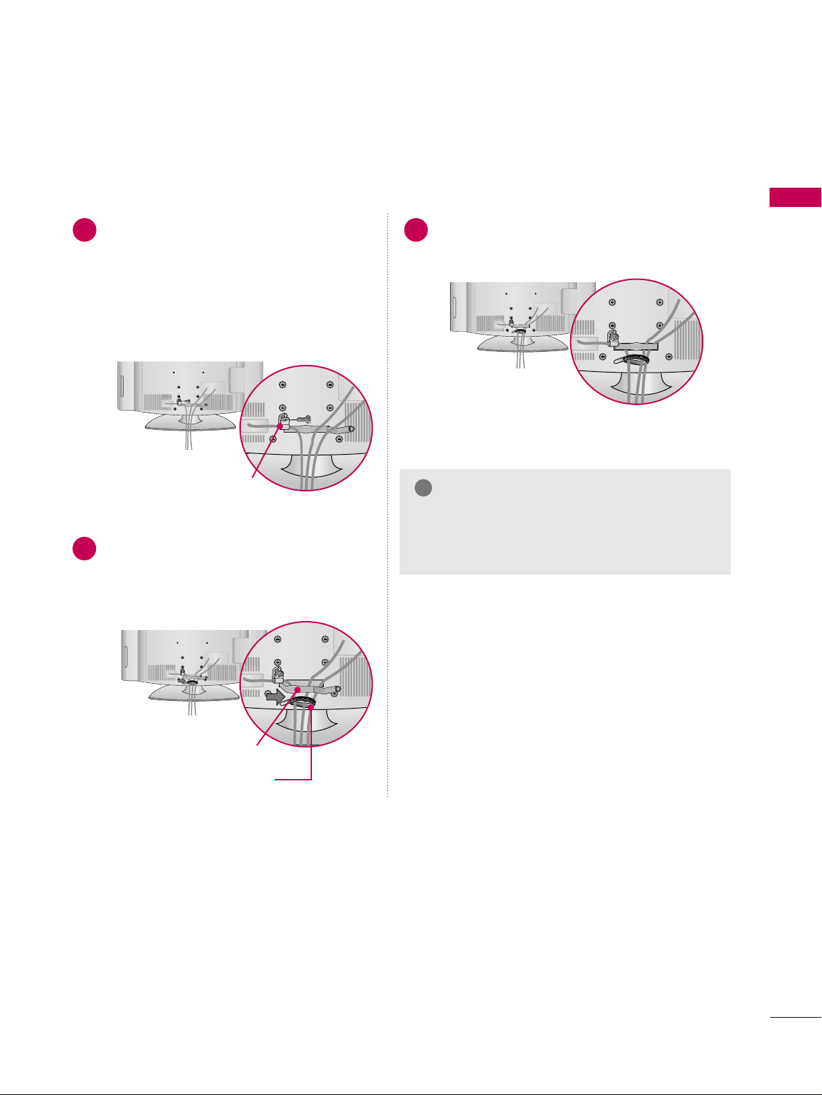
CABLE MANAGEMENT
■
Image shown may differ from your TV.
Connect the cables as necessary.
To connect additional equipment, see the
EXTERNAL EQUIPMENT SETUP section.
Secure the power cable with the
PROTECTIVE BRACKET and the screw as
shown. It will help prevent the power cable
from being removed by accident.
Install the CABLE MANAGEMENT CLIP as
shown.
If your TV has the CABLE HOLDER, install it
as shown and bundle the cables.
1
2
Put the cables inside the CABLE MANAGEMENT
CLIP and snap it closed.
3
PROTECTIVE BRACKET
(This feature is not available
for all models.)
GG
Do not hold the CABLE MANAGEMENT CLIP
when moving the TV.
- If the TV is dropped, you may be injured or the
product may be broken.
NOTE
!
CABLE MANAGEMENT CLIP
CABLE HOLDER
PREPARATION
14
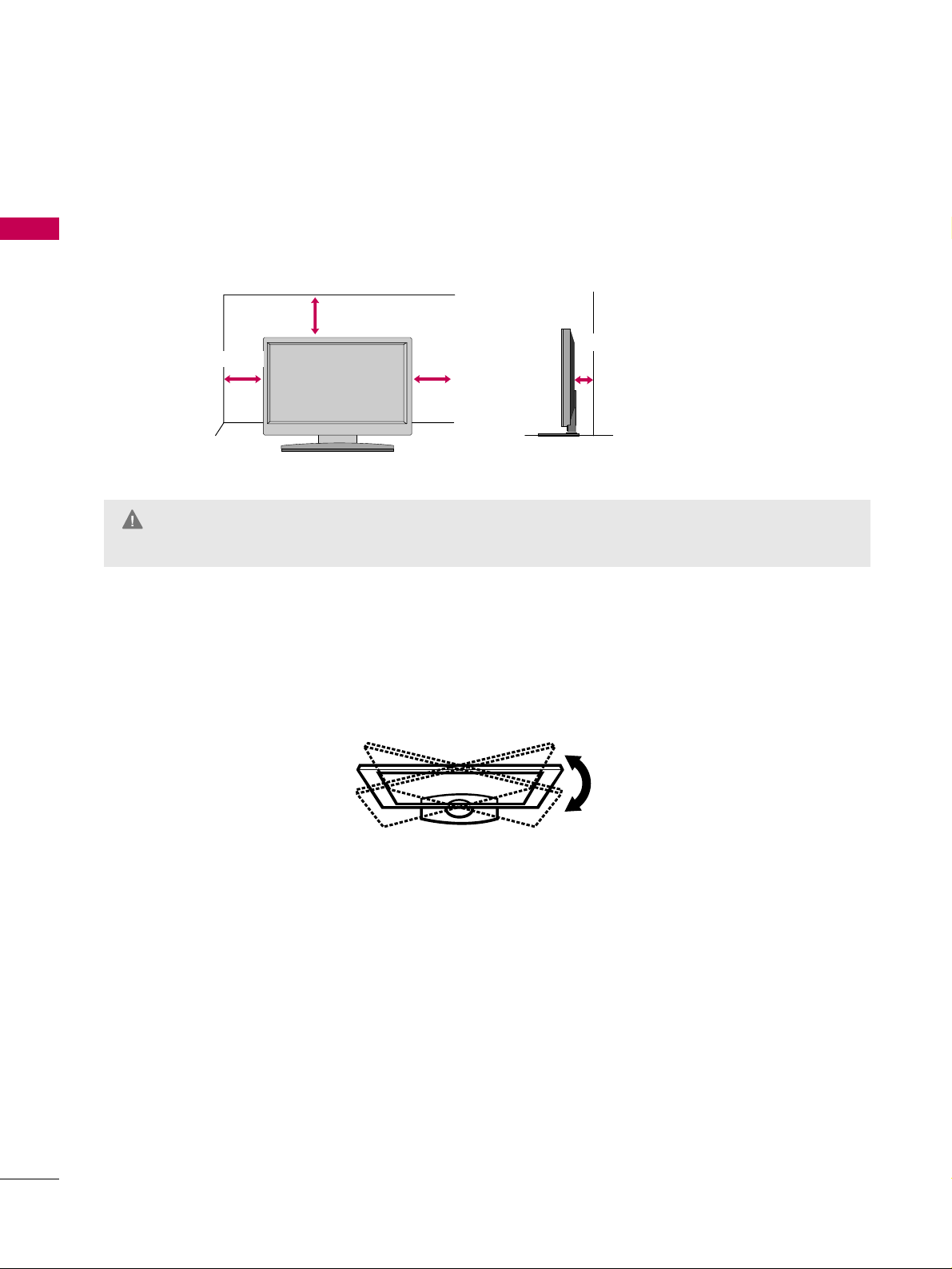
PREPARATION
DESKTOP PEDESTAL INSTALLATION
For proper ventilation, allow a clearance of 4 inches on all four sides.
■
Image shown may differ from your TV.
* This feature is not available for all models.
4 inches
4 inches
4 inches
4 inches
SWIVEL STAND
The TV can be conveniently swivelled on its stand 90° to the left or right to provide the optimum viewing angle.
GG
Ensure adequate ventilation by following the clearance recommendations.
GG
Do not mount near or above any type of heat source.
CAUTION
 Loading...