

LG 42LG350H User manual
Please read this manual carefully before operating
your TV.
Retain it for future reference.
Record model number and serial number of the TV.
Refer to the label on the back cover and quote this
information.
To your dealer when requiring service.
Model :
Serial No. :
LCD TV
OWNER’S MANUAL
LCD TV MODELS
3322LLGG3355
****
3377LLGG3355
****
4422LLGG3355
****
Trade Mark of the DVB Digital Video
Broadcasting Project (1991 to 1996)
ENGLISH
II DD NNuummbbeerr((ss)) ::
6605 : 32LG 350H -TA
6606 : 37LG350H-TA
6607 : 42LG350H-TA
PP// NNOO :: MMFFLL3344444411 6677 77 ((00 990066--RR EEVV00 22))
PP rriinnttee dd iinn KKoo rree aa
Manufactured under license from Dolby Laboratories. “
Dolby
“and the double-D symbol are
trademarks of Dolby Laboratories.
• There is a possibility that when HDMI mode, some DVD players do not make SPDIF
sound. At that time, set the output of the digital audio of the DVD player to PCM.
(In HDMI, DOLBY DIGITAL PLUS is not supported.)
HDMI, the HDMI logo and High-Definition Multimedia Interface are
trademarks or registered trademarks of HDMI Licensing LLC.
1
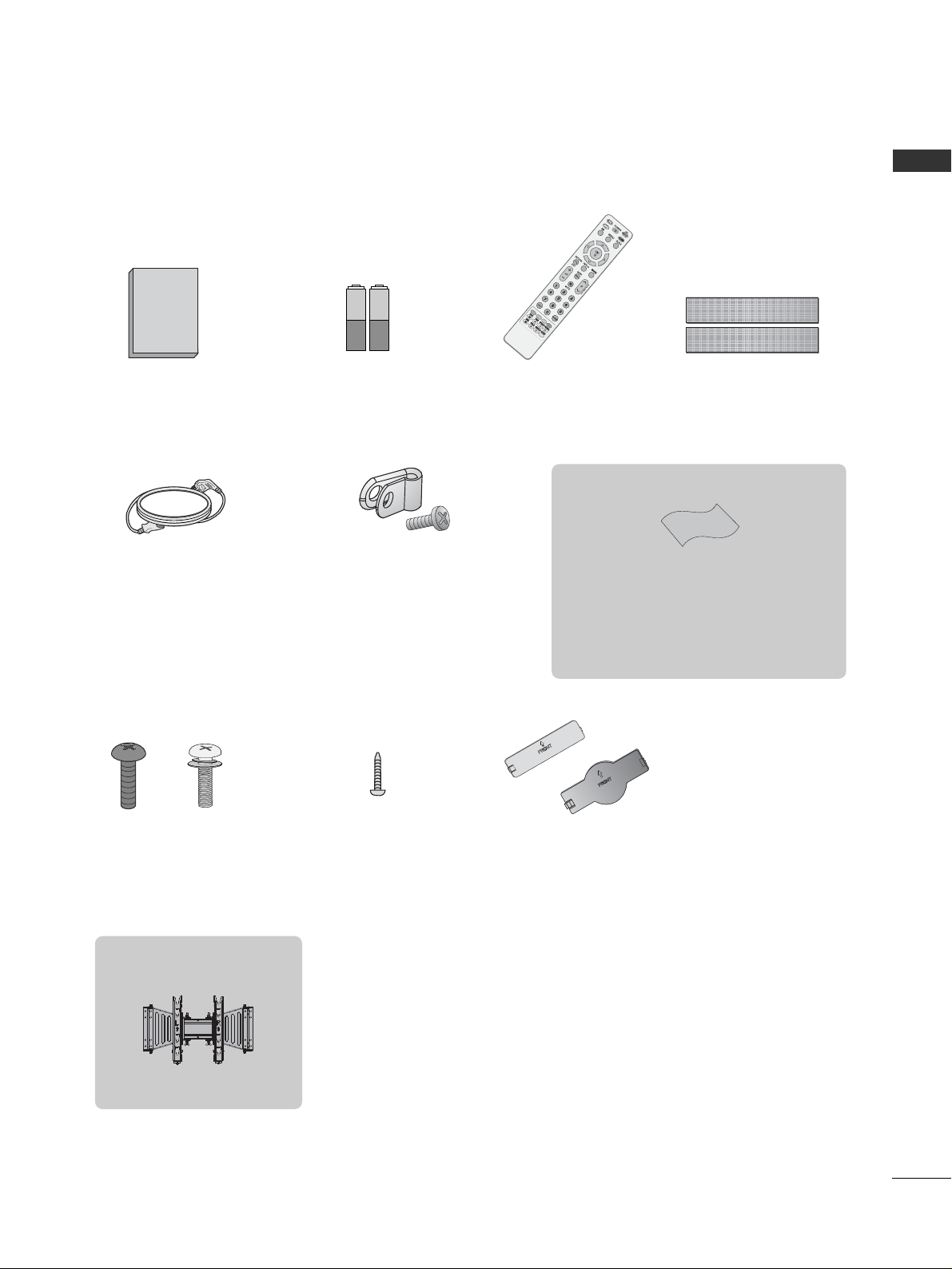
ACCESSORIES
ACCESSORIES
Ensure that the following accessories are included with your TV. If an accessory is missing, please contact the
dealer where you purchased the TV.
The accessories included may differ from the images below.
Batteries Remote Control
Power Cord
Polishing Cloth
Polishing cloth for use on the screen.
Lightly wipe any stains or fingerprints on the surface
of the TV with the polishing cloth.
Do not use excessive force. This may cause scratching
or discolouration.
This item is not included for all models.
Screw for stand fixing
(Refer to P.6)
Bolts for stand assembly
(Refer to P.6)
x 4 x 4
Protection Cover
(Refer to P.9)
or
Owner’s Manual
Protective Bracket and Bolt for Power Cord
(
This item is not included for all models.
)
(Refer to P.8)
Dual Lock™
(
This item is not included for all
models.
)
(Refer to P.9)
Wall Mounting Bracket
(Separate purchase)
AW-47LG30M

CONTENTS
ACCESSORIES
. . . . . . . . . . . . . . . . . . . . . . . . . . . . . . . . . . . . . . . . . . . . .
1
PREPARATION
Front Panel Controls . . . . . . . . . . . . . . . . . . . . . . . . 4
Back Panel Information . . . . . . . . . . . . . . . . . . . . . . 5
Stand Installation . . . . . . . . . . . . . . . . . . . . . . . . . . . 6
Attaching the TV to a desk . . . . . . . . . . . . . . . . . . . . 6
Careful installation advice . . . . . . . . . . . . . . . . . . . 7
Back Cover for Wire Arrangement . . . . . . . . . . . . . . 8
Swivel Stand . . . . . . . . . . . . . . . . . . . . . . . . . . . . . . . . 8
How to use Dual Lock™ . . . . . . . . . . . . . . . . . . . . . 9
Protection cover . . . . . . . . . . . . . . . . . . . . . . . . . . . . .9
Desktop Pedestal Installation . . . . . . . . . . . . . . . . . 10
Wall Mount: Horizontal installation . . . . . . . . . . . . 10
Antenna Connection . . . . . . . . . . . . . . . . . . . . . . . . 11
EXTERNAL EQUIPMENT SETUP
HD Receiver Setup . . . . . . . . . . . . . . . . . . . . . . . . 12
DVD Setup . . . . . . . . . . . . . . . . . . . . . . . . . . . . . . . . 14
VCR Setup . . . . . . . . . . . . . . . . . . . . . . . . . . . . . . . . 16
Speaker Output Setup . . . . . . . . . . . . . . . . . . . . . . .18
Audio Out Setup . . . . . . . . . . . . . . . . . . . . . . . . . . .18
Digital Audio Out Setup . . . . . . . . . . . . . . . . . . . . . .19
Other A/V Source Setup . . . . . . . . . . . . . . . . . . . . 20
Usb in Setup . . . . . . . . . . . . . . . . . . . . . . . . . . . . . . .20
PC Setup . . . . . . . . . . . . . . . . . . . . . . . . . . . . . . . . . .21
- Screen Setup for PC Mode . . . . . . . . . . . . . . . 24
WATCHING TV / PROGRAMME CONTROL
Remote Control Key Functions . . . . . . . . . . . . . . . . 28
Turning on the TV . . . . . . . . . . . . . . . . . . . . . . . . . . 30
Initializing setup . . . . . . . . . . . . . . . . . . . . . . . . 30
Programme Selection . . . . . . . . . . . . . . . . . . . . . . . 30
Volume Adjustment . . . . . . . . . . . . . . . . . . . . . . . . . 30
On-Screen Menus Selection and Adjustment . . . . 31
Auto Programme Tuning . . . . . . . . . . . . . . . . . . . . . 32
Manual Programme Tuning (In Digital Mode) . . . . 33
Manual Programme Tuning (In Analogue Mode) . . 34
Programme Edit . . . . . . . . . . . . . . . . . . . . . . . . . . . . 36
Booster . . . . . . . . . . . . . . . . . . . . . . . . . . . . . . . . . . 39
Software Update . . . . . . . . . . . . . . . . . . . . . . . . . . . 40
Diagnostics . . . . . . . . . . . . . . . . . . . . . . . . . . . . . . . 42
Selecting the Programme Table . . . . . . . . . . . . . . 43
Input Label . . . . . . . . . . . . . . . . . . . . . . . . . . . . . . . 44
TO USE THE USB DEVICE
When Connecting the USB Device . . . . . . . . . . . . 45
Photo List . . . . . . . . . . . . . . . . . . . . . . . . . . . . . . . . 46
Music List . . . . . . . . . . . . . . . . . . . . . . . . . . . . . . . . . 50
EPG (ELECTRONIC PROGRAMME
GUIDE) (IN DIGITAL MODE)
Switch On/ Off EPG . . . . . . . . . . . . . . . . . . . . . . . . 53
Select Programme . . . . . . . . . . . . . . . . . . . . . . . . . . 53
Button Function in NOW/NEXT Guide Mode . . . . . 53
Button Function in 8 Day Guide Mode . . . . . . . . . . 54
Button Function in Date Change Mode . . . . . . . . . . 54
PICTURE CONTROL
Picture Size (Aspect Ratio) Control . . . . . . . . . . . . 55
Preset Picture Settings
- Picture Mode-Preset . . . . . . . . . . . . . . . . . . . . 57
Manual Picture Adjustment
- Picture Mode-User option . . . . . . . . . . . . . . . . 58
Picture Improvement Technology . . . . . . . . . . . . . . . . . 59
Advanced - Black(Darkness) Level . . . . . . . . . . . . . 60
Eye Care . . . . . . . . . . . . . . . . . . . . . . . . . . . . . . . . . . 61
Advanced - Film Mode . . . . . . . . . . . . . . . . . . . . . . 62
Picture Reset . . . . . . . . . . . . . . . . . . . . . . . . . . . . . . 63
Power Indicator . . . . . . . . . . . . . . . . . . . . . . . . . . . . 64
2
CONTENTS

CONTENTS
SOUND & LANGUAGE CONTROL
Auto Volume Leveler . . . . . . . . . . . . . . . . . . . . . . . . 65
Preset Sound Settings - Sound Mode . . . . . . . . . . 66
Sound Setting Adjustment - User Mode . . . . . . . . . . 67
Balance . . . . . . . . . . . . . . . . . . . . . . . . . . . . . . . . . . . 68
Audio Reset . . . . . . . . . . . . . . . . . . . . . . . . . . . . . . . 69
I/II
-
Stereo/Dual Reception (In Analogue Mode Only)
. . . . 70
-
NICAM Reception (In Analogue Mode Only) . . . . . . .
71
- Speaker Sound Output Selection . . . . . . . . . . 71
On-Screen Menu Language/Country Selection
. . . . . . . . 72
Language selection (In Digital Mode only) . . . . . . 73
TIME SETTING
Clock Setup . . . . . . . . . . . . . . . . . . . . . . . . . . . . . . . 74
Auto On/ Off Timer Setting . . . . . . . . . . . . . . . . . . 75
Auto Shut-off Setting . . . . . . . . . . . . . . . . . . . . . . . 76
Time Zone Setup . . . . . . . . . . . . . . . . . . . . . . . . . . . 76
Sleep Timer Setting . . . . . . . . . . . . . . . . . . . . . . . . . 77
Alarm setting . . . . . . . . . . . . . . . . . . . . . . . . . . . . . . 77
PARENTAL CONTROL / RATINGS
Set Password & Lock System . . . . . . . . . . . . . . . . . 78
Block Programme . . . . . . . . . . . . . . . . . . . . . . . . . . . 79
Parental Control . . . . . . . . . . . . . . . . . . . . . . . . . . . 80
Key Lock . . . . . . . . . . . . . . . . . . . . . . . . . . . . . . . . . . 81
TELETEXT
Switch On/ Off . . . . . . . . . . . . . . . . . . . . . . . . . . . . 82
SIMPLE Text . . . . . . . . . . . . . . . . . . . . . . . . . . . . . . . 82
TOP Text . . . . . . . . . . . . . . . . . . . . . . . . . . . . . . . . . 82
FASTEXT . . . . . . . . . . . . . . . . . . . . . . . . . . . . . . . . . 83
Special Teletext Functions . . . . . . . . . . . . . . . . . . . . 83
APPENDIX
Initializing (Reset to original factory setting) . . . . 84
Troubleshooting . . . . . . . . . . . . . . . . . . . . . . . . . . . 85
Maintenance . . . . . . . . . . . . . . . . . . . . . . . . . . . . . . 87
Product Specifications . . . . . . . . . . . . . . . . . . . . . . 88
Programming the Remote control . . . . . . . . . . . . . .89
IR Codes . . . . . . . . . . . . . . . . . . . . . . . . . . . . . . . . . 90
External Control Device Setup . . . . . . . . . . . . . . . 92
3
PREPARATION
4
PREPARATION
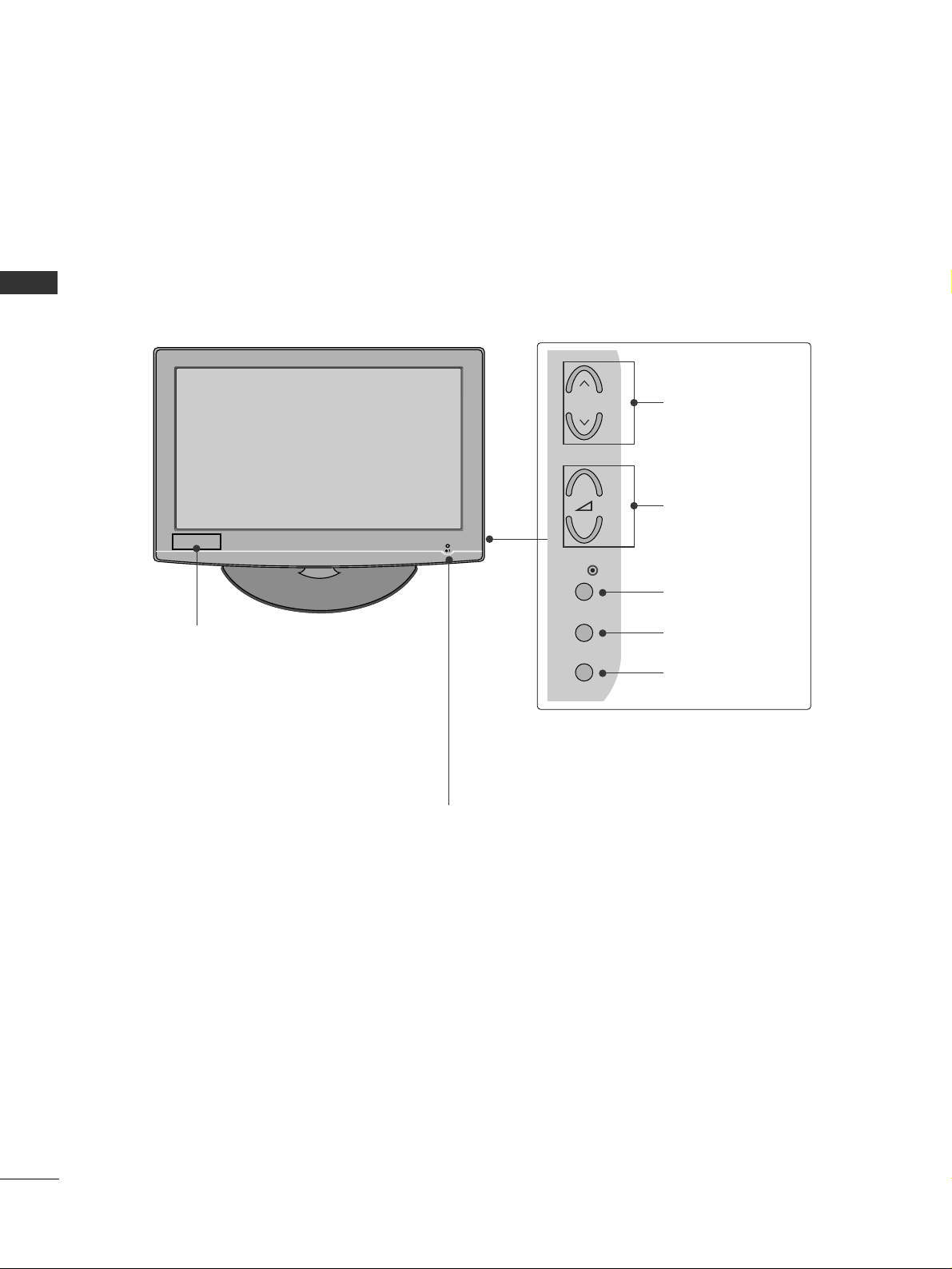
FRONT PANEL CONTROLS
■
Image shown may differ from your TV.
POWER
Remote Control Sensor
Power/Standby Indicator
• illuminates red in standby mode.
• illuminates blue when the TV is switched on.
Note:
You can adjust
PPoowweerr IInnddiiccaattoorr
in
the
OPTION menu.
MENU
INPUT
OK
+
-
P
PROGRAMME
VOLUME
OK
MENU
INPUT
Clock LED
32/37/42LG35
**
PREPARATION
5
(
CONTROL & SER & SERVICE
)
SPEAKER
OUTPUT
(
STEREO
)
VOLUME
CONTROL
/ DVI IN
2 3 4 5
131210
8
6
7
9 11
15
14
1
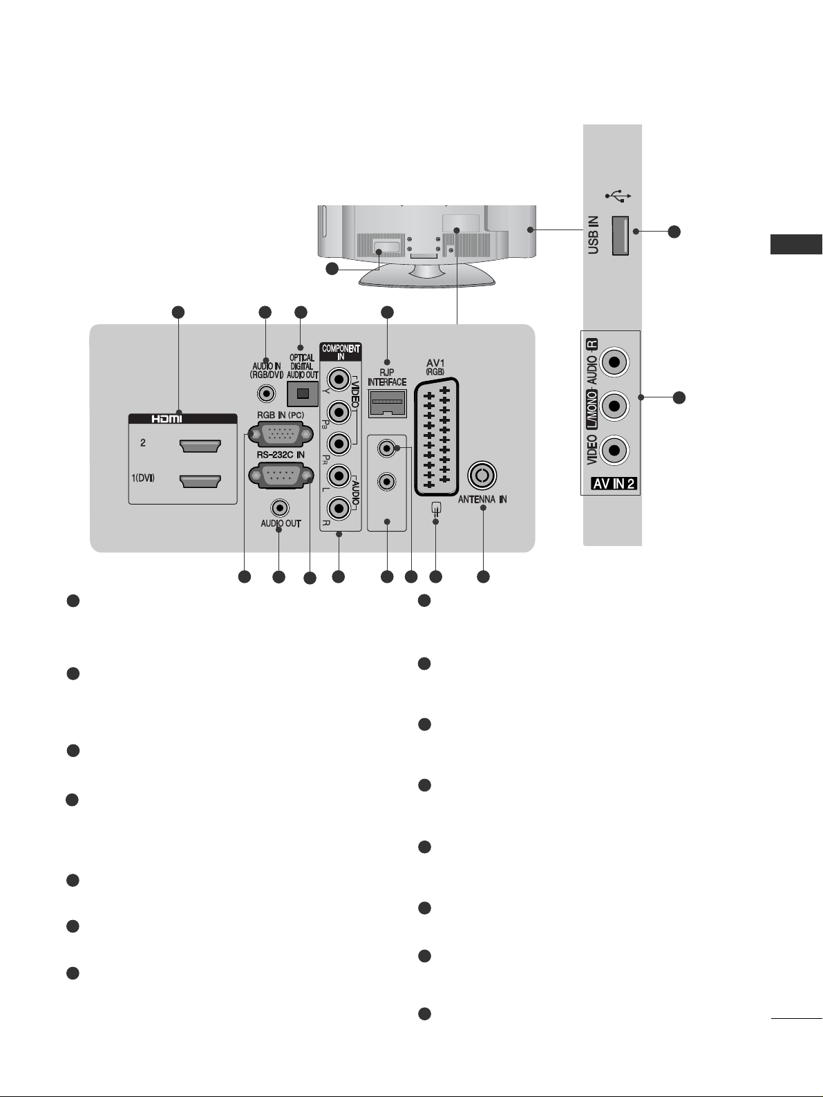
Power Cord Socket
This TV operates on an AC power. The voltage is
indicated on the Specifications page. Never
attempt to operate the TV on DC power.
HDMI/DVI IN Input
Connect an HDMI signal to HDMI IN.
Or DVI(VIDEO)signal to HDMI/DVI port with DVI
to HDMI cable.
RGB/DVI Audio Input
Connect the audio from a PC or DTV.
OPTICAL DIGITAL AUDIO OUT
Connect digital audio to various types of equipment.
Connect to a Digital Audio Component.
Use an Optical audio cable.
RJP INTERFACE
Connect control line (RJ45) for RJP(Remote Jack pack)
RGB IN Input
Connect the output from a PC.
Audio Output
Connect to the Home Theater.(or amp)
RS-232C IN (CONTROL & SERVICE) PORT
Connect to the RS-232C port on a PC.
This port is used for Service or Hotel mode.
Component Input
Connect a component video/audio device to
these jacks.
SPEAKER OUTPUT(STEREO)
The phone socket for external speaker is on this
jack.
VOLUME CONTROL
Use the VOLUME CONTROL to adjust sound
from the SPEAKER OUTPUT.
Euro Scart Socket (AV1(RGB))
Connect scart socket from an external device to
this jack.
Antenna Input
Connect antenna or cable to this jack.
Audio/Video Input(AV IN 2)
Connect audio/video output from an external
device to these jacks.
USB Input
Connect USB storage device to this jack.
1
2
3
4
5
6
7
8
9
10
11
12
13
14
15
BACK PANEL INFORMATION
■
Image shown may differ from your TV.
PREPARATION
6
PREPARATION
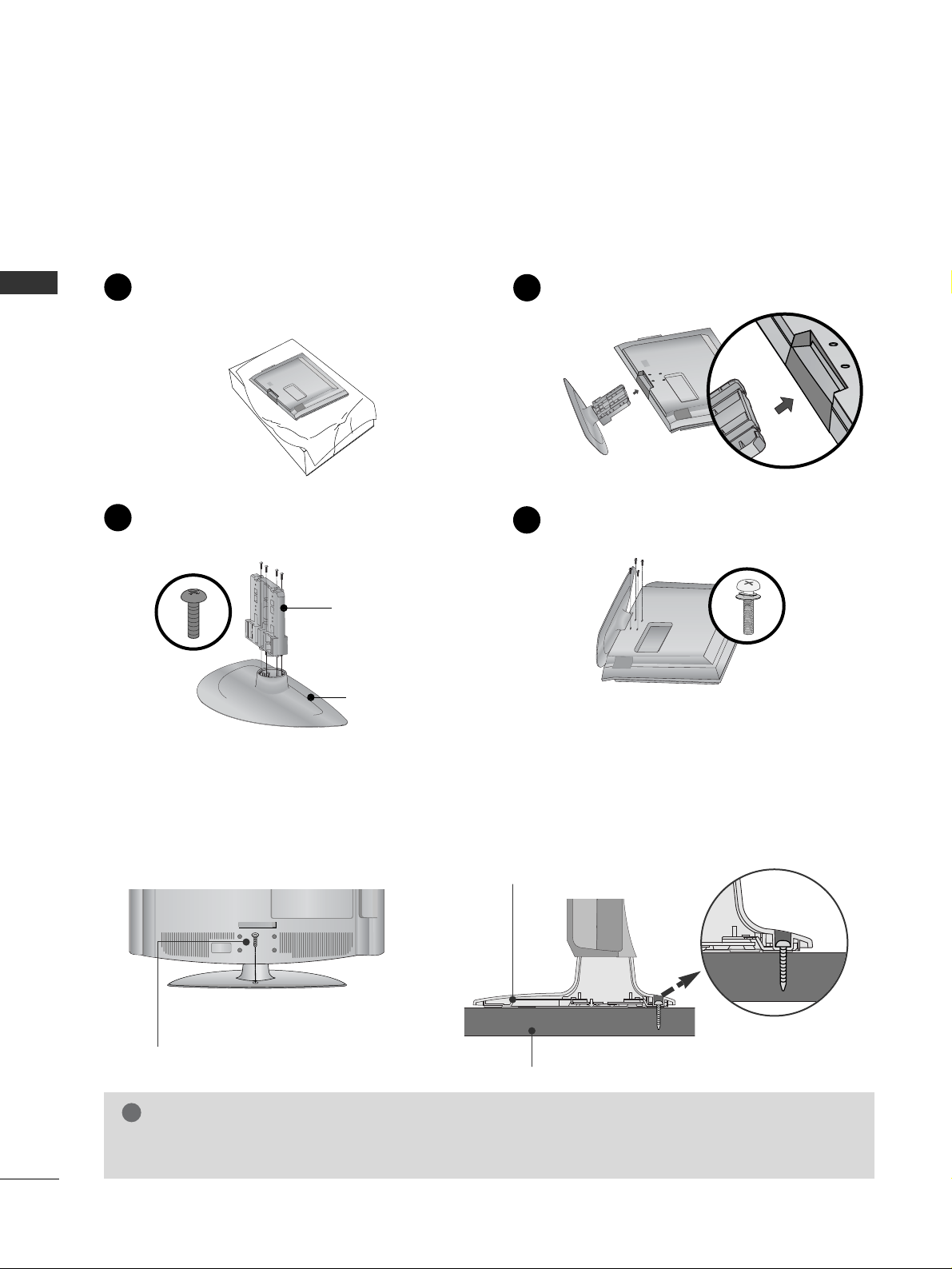
STAND INSTALLATION
■
Image shown may differ from your TV.
■
When assembling the desk type stand, check whether the bolt is fully tightened. (If not tightened fully, the
product can tilt forward after the product installation.) If you tighten the bolt with excessive force, the bolt can
deviate from abrasion of the tightening part of the bolt.
Assemble the parts of the
SS TT AANN DD BBOODDYY
with
SS TT AANN DD BBAASSEE
of the TV.
2
Assemble the TV as shown.
3
Fix the 4 bolts securely using the holes in the
back of the TV.
4
SS TT AA NNDD BBOO DDYY
SS TT AANN DD BBAASSEE
Carefully place the TV screen side down on a
cushioned surface to protect the screen from
damage.
1
ATTACHING THE TV TO A DESK
WARNING
!
GG
To prevent TV from falling over, the TV should be securely attached to the floor/wall per installation
instructions. Tipping, shaking, or rocking the machine may cause injury.
The TV must be attached to desk so it cannot be pulled in a forward/backward direction, potentially causing
injury or damaging the product. Use only an attached screw.
1-Screw
(provided as parts of the product)
Desk
Stand
PREPARATION
7
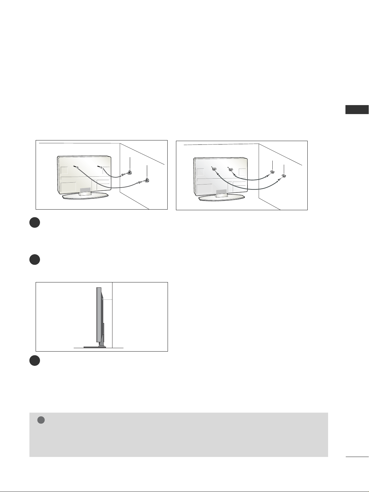
CAREFUL INSTALLATION ADVICE
■
You should purchase necessary components to fix the TV to the wall on the market.
■
Position the TV close to the wall to avoid the possibility of it falling when pushed.
■
The instructions shown below are a safer way to set up the TV, which is to fix it to the wall, avoiding the
possibility of it falling forwards if pulled. This will prevent the TV from falling forward and causing injury. This
will also prevent the TV from damage. Ensure that children do not climb or hang from the TV.
NOTE
!
G
When moving the TV undo the cords first.
G
Use a platform or cabinet strong and large enough to support the size and weight of the TV.
G
To use the TV safely make sure that the height of the bracket on the wall and on the TV is the same.
3
1
2
Use the eye-bolts or TV brackets/bolts to fix the TV to the wall as shown in the picture.
(If your TV has bolts in the eyebolts, loosen these bolts.)
* Insert the eye-bolts or TV brackets/bolts and tighten them securely in the upper holes.
Secure the wall brackets with the bolts on the wall. Match the height of the bracket that is mounted on the
wall.
3
Use a sturdy rope to tie the TV. It is safer to tie the rope so it becomes horizontal between the wall and the
TV.
2
2
1
PREPARATION
8
PREPARATION
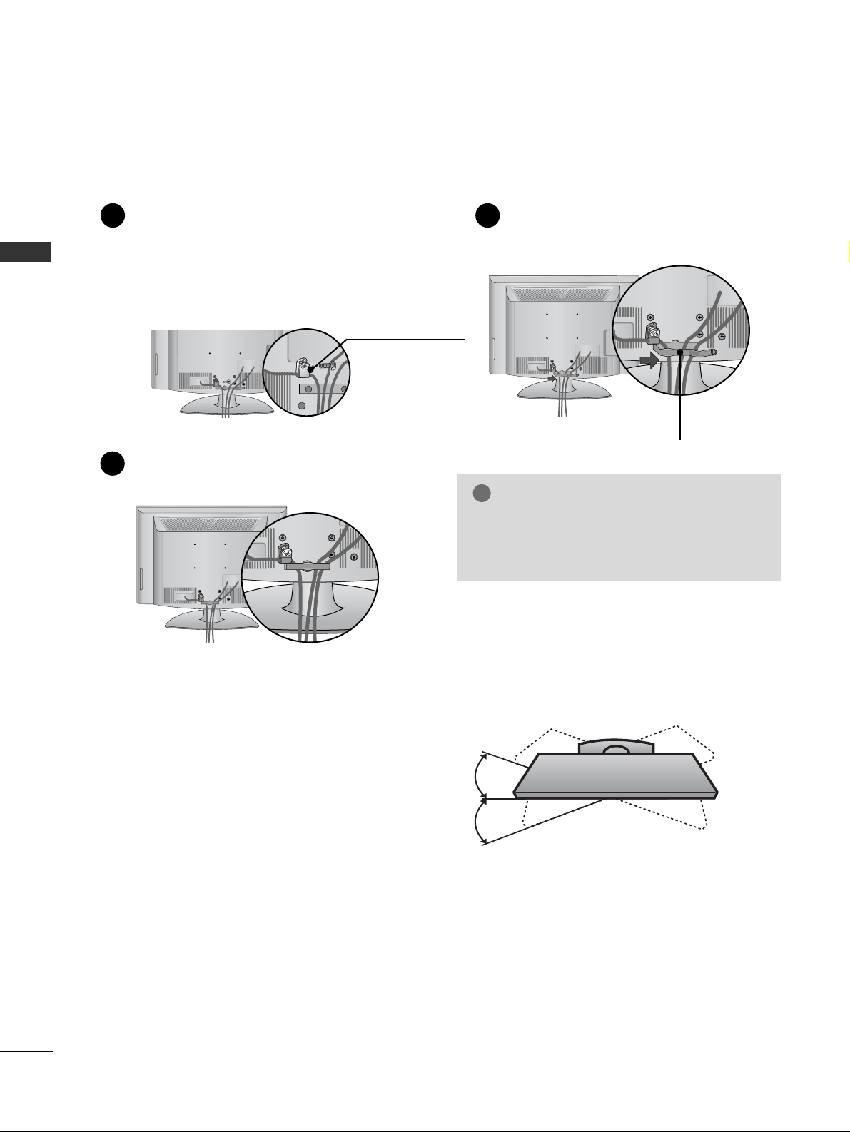
BACK COVER FOR WIRE ARRANGEMENT
A
Image shown may differ from your TV.
Connect the cables as necessary.
To connect additional equipment, see the
EXTERNAL EQUIPMENT SETUP section.
Secure the power cable with the PROTECTIVE BRACKET
and the screw as shown. It will help prevent the power cable
from being removed by accident.
Install the CABLE MANAGEMENT CLIP as
shown.
1
2
Put the cables inside the CABLE MANAGEMENT
CLIP and snap it closed.
3
GG
Do not hold the CABLE MANAGEMENT
CLIP when moving the TV.
- If the TV is dropped, you may be injured or
the product may be broken.
NOTE
!
SWIVEL STAND
After installing the TV, you can adjust the TV manually
to the left or right direction by 20 degrees to suit your
viewing position.
PROTECTIVE
BRACKET
(This feature is not
available for all models.)
CABLE MANAGEMENT CLIP
PREPARATION
9
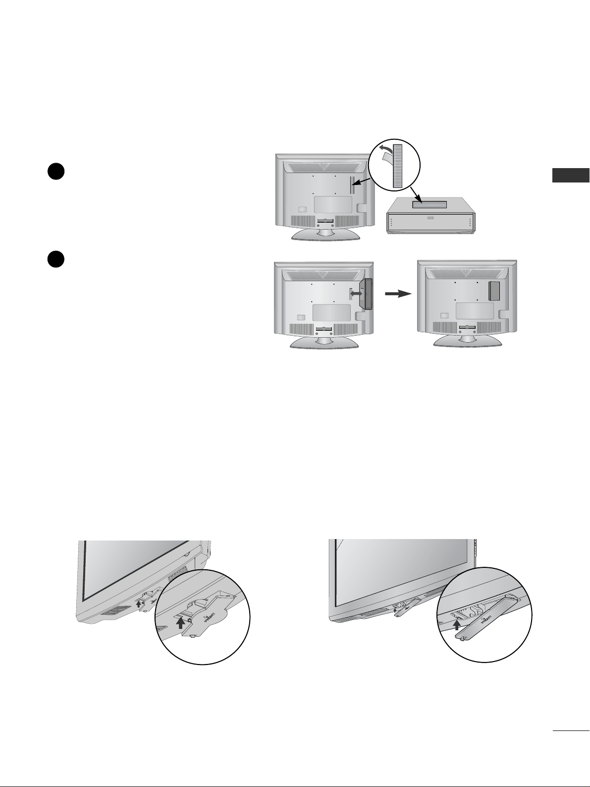
HOW TO USE DUAL LOCK™
(This feature is not available for
all models.)
Fix the set-top box to the TV and use it when you want to.
After removing the protection paper from
the Dual Lock, stick it to the TV and the
set-top box as shown.
Attach the set-top box to the TV by pressing
the Velcro strips together.
1
2
PROTECTION COVER
■
Image shown may differ from your TV.
When installing the wall-mounted unit, use the protection cover for desk-type stand installation. Insert the
PPRROOTT EE CC TTIIOONN CCOOVVEERR
into the TV until clicking sound.
or
PREPARATION
10
PREPARATION
A
The TV can be installed in various ways such as on
a wall, or on a desktop etc.
A
The TV is designed to be mounted horizontally.
Power Supply
Circuit breaker
EARTHING
Ensure that you connect the earth wire to prevent
possible electric shock. If grounding methods are not
possible, have a qualified electrician install a separate
circuit breaker.
Do not try to earth the TV by connecting it to telephone wires, lightening rods or gas pipes.
DESKTOP PEDESTAL INSTALLATION
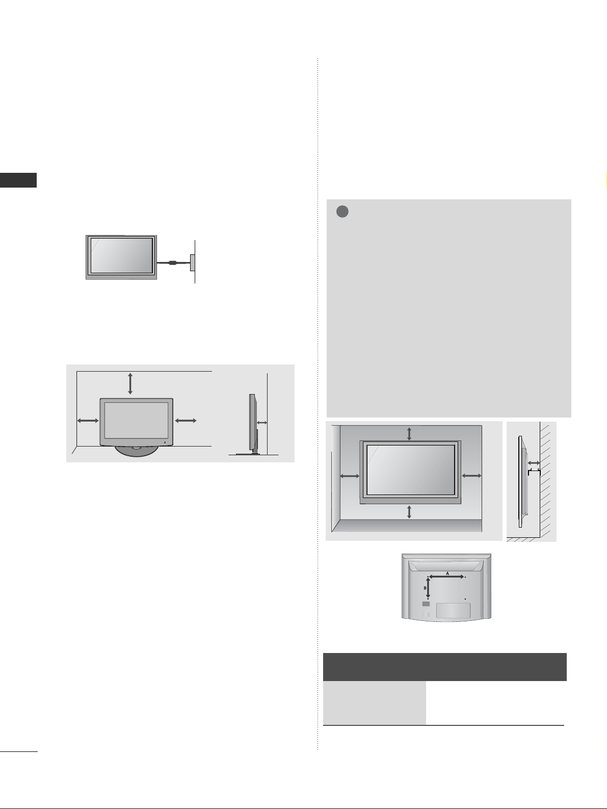
For adequate ventilation allow a clearance of 4”
(10cm) all around the TV.
WALL MOUNT: HORIZONTAL
INSTALLATION
A
We recommend the use of a LG Brand wall mounting
bracket when mounting the TV to a wall.
A
We recommend that you purchase a wall mounting
bracket which supports VESA standard.
A
LG recommends that wall mounting be performed by a
qualified professional installer.
4 inches
4 inches
4 inches
4 inches
4 inches
NOTE
!
G Should Install wall mount on a solid wall perpendicular to
the floor.
G Should use a special wall mount, if you want to install it to
ceiling or slanted wall.
G The surface that wall mount is to be mounted on should
be of sufficient strength to support the weight of TV set;
e.g. concrete, natural rock, brick and hollow block.
G Installing screw type and length depends on the wall
mount used. Further information, refer to the instructions
included with the mount.
G LG is not liable for any accidents or damage to property or
TV due to incorrect installation:
- Where a non-compliant VESA wall mount is used.
- Incorrect fastening of screws to surface which may cause
TV to fall and cause personal injury.
- Not following the recommended Installation method.
Model
VESA
(A *B)
Standard
Screw
Quantity
32LG35**
37LG35**
42LG35**
200 * 10 0
200 * 200
200 * 200
M4
M6
M6
4
4
4
4 inches
4 inches 4 inches 4 inches
PREPARATION
11
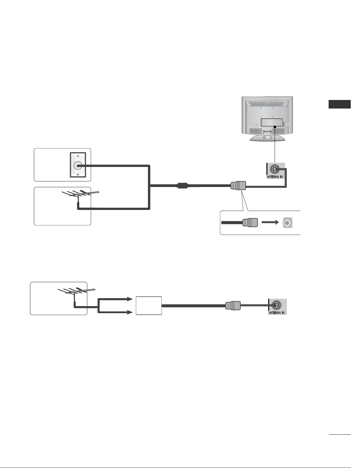
■
For optimum picture quality, adjust antenna direction.
■
An antenna cable and converter are not supplied.
Multi-family Dwellings/Apartments
(Connect to wall antenna socket)
Single-family Dwellings /Houses
(Connect to wall jack for outdoor antenna)
Outdoor
Antenna
(VHF, UHF)
Wall
Antenna
Socket
RF Coaxial Wire (75 ohm)
ANTENNA CONNECTION
Antenna
UHF
Signal
Amplifier
VHF
■
In poor signal areas, to achieve better picture quality it may be necessary to install a signal amplifier to the
antenna as shown above.
■
If signal needs to be split for two TVs, use an antenna signal splitter for connection.
■
To prevent damage do not connect to the mains outlet until all connections are made between the devices.
EXTERNAL EQUIPMENT SETUP
12
EXTERNAL EQUIPMENT SETUP
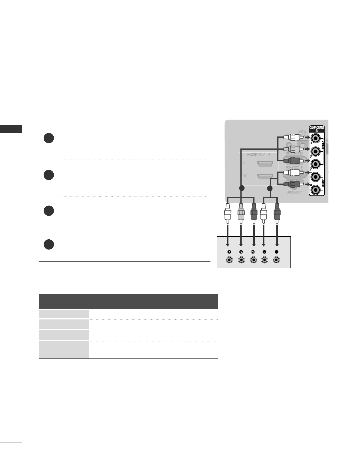
Connect the video outputs (Y, PB
, PR
)
of the digital set
top box to the
CC OOMMPPOO NNEENNTT II NN VVII DDEEOO
jacks on the TV.
Connect the audio output of the digital set-top box to
the
CC OOMMPPOO NNEENNTT II NN AAUU DDII OO
jacks on the TV.
Turn on the digital set-top box.
(
Refer to the owner’s manual for the digital set-top box.
)
Select
CCoomm pp oo nneenn tt
input source using the
IINN PP UU TT
button
on the remote control.
2
3
4
1
HD RECEIVER SETUP
■
To avoid damaging any equipment, never plug in any power cords until you have finished connecting all equipment.
■
This section on EXTERNAL EQUIPMENT SETUP mainly uses diagrams for the 42LG35**models.
■
Image shown may differ from your TV.
Connecting with a component cable
/ DVI IN
1
2
■
This TV can receive Digital RF/Cable signals without an external digital set-top box. However, if you do receive
Digital signals from a digital set-top box or other digital external device, refer to the diagram as shown below.
Signal
480i/576i
480p/576p
720p/1080i
10 8 0 p
Component
O
O
O
O
(50/60Hz only)
HDMI
X
O
O
O
(24Hz/30Hz/50Hz/60Hz)
EXTERNAL EQUIPMENT SETUP
/ DVI IN
/ DVI IN
/ DVI IN
13
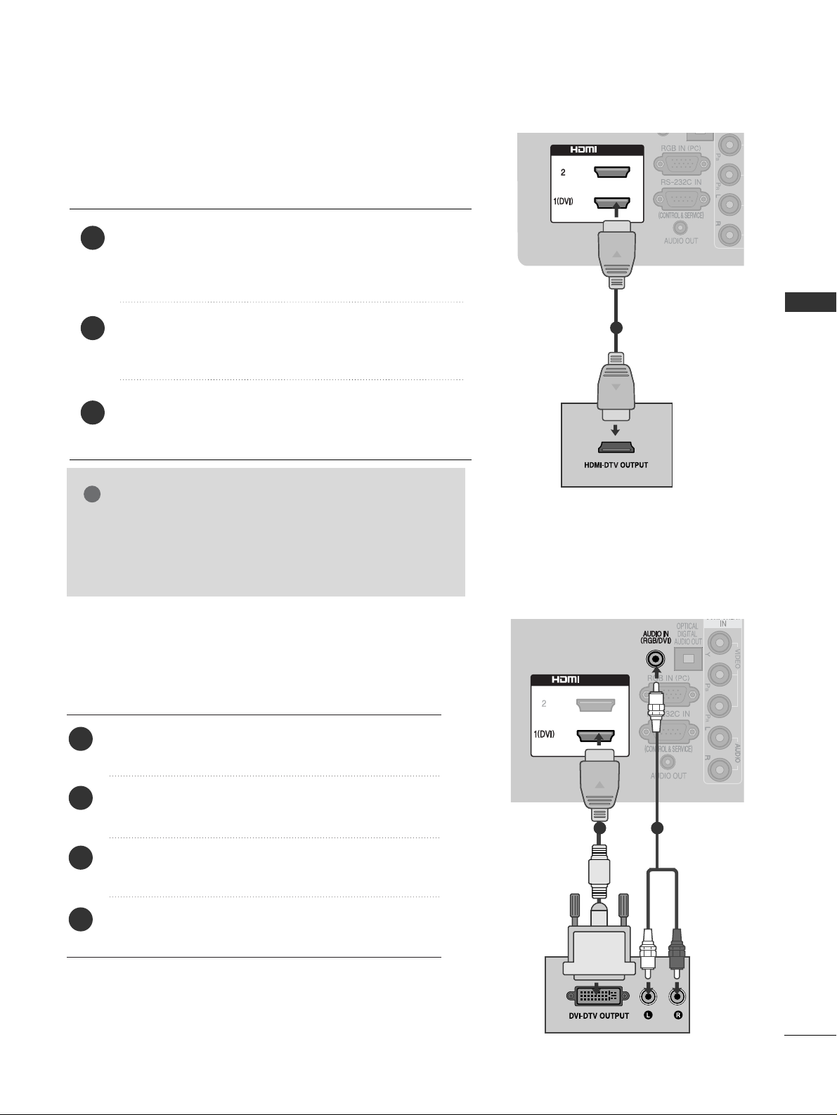
Connecting a set-top box with an HDMI cable
Connect the HDMI output of the digital set-top box to the
HHDDMMII//DD VVII IINN 11(( DDVVII))
or
HHDDMMII//DD VVII IINN 22
jack on the
TV.
Turn on the digital set-top box.
(
Refer to the owner’s manual for the digital set-top box.
)
Select HDMI1 or HDMI2 input source using the
IINNPPUU TT
but-
ton on the remote control.
2
3
1
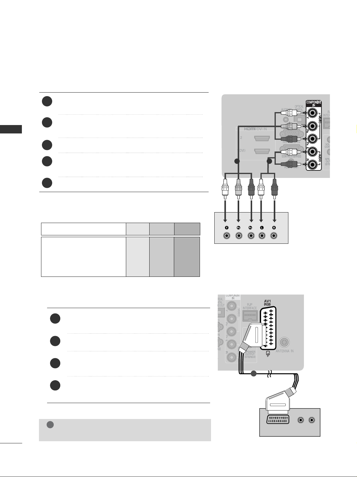
1
Connect the digital set-top box to
HHDD MMII//DD VV II II NN
11((DD VV II ))
jack on the TV.
Connect the audio output of the digital set-top box to
the
AA UUDD IIOO IINN ((RRGG BB// DDVVII))
jack on the TV.
Turn on the digital set-top box. (Refer to the owner’s
manual for the digital set-top box.
)
Select
HHDD MMII 11
input source using the
IINN PP UU TT
button
on the remote control.
2
3
4
1
Connecting with a HDMI to DVI cable
1
2
GG
Check that your HDMI cable is version 1.3 or higher.
If the HDMI cables don’t support HDMI version 1.3, flickering or no screen display can result. Please use the latest
cables that support at least HDMI version 1.3.
NOTE
!
EXTERNAL EQUIPMENT SETUP
(R) AUDIO (L)
AUDIO/
VIDEO
14
EXTERNAL EQUIPMENT SETUP
DVD SETUP
When connecting with a component cable
Component Input ports
To achieve better picture quality, connect a DVD player to
the component input ports as shown below.
Component ports on the TV
YPBP
R
Video output ports
on DVD player
Y
Y
Y
Y
PB
B-Y
Cb
Pb
P
R
R-Y
Cr
Pr
Connect the video outputs (Y, P
B, PR
)
of the DVD to the
CC OOMMPPOO NNEENNTT II NN VVII DDEEOO
jacks on the TV.
Connect the audio outputs of the DVD to the
CC OOMMPPOO NNEENNTT II NN AAUU DDII OO
jacks on the TV.
Turn on the DVD player, insert a DVD.
Select
CCoomm pp oo nneenn tt
input source using the
IINN PP UU TT
button
on the remote control.
Refer to the DVD player's manual for operating instructions.
2
3
4
5
1
1 2
1
2
3
4
1
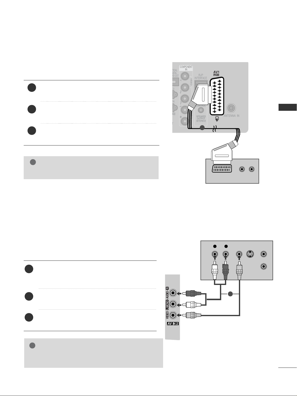
Connecting with a Euro Scart cable
Connect the Euro scart socket of the DVD to the
AA VV 11((RRGGBB))
Euro scart socket on the TV.
Turn on the DVD player, insert a DVD.
Select
AAVV 11
input source using the
IINN PP UU TT
button on
the remote control.
Refer to the DVD player's manual for operating
instructions.
NOTE
!
GG
Any Euro scart cable used must be signal shielded.
EXTERNAL EQUIPMENT SETUP
/ DVI IN
15
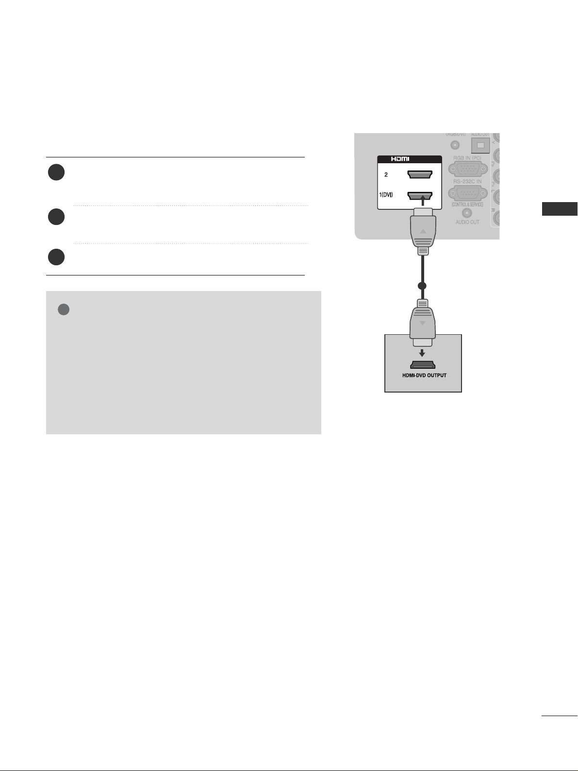
Connecting the HDMI cable
Connect the HDMI output of the DVD to the
HHDDMMII//DD VVII IINN 11 ((DDVVII ))orHHDDMMII //DD VVII IINN 22
jack on
the TV.
Select
HHDDMMII11orHHDDMMII22
input source using the
IINN PP UU TT
button on the remote control.
Refer to the DVD player's manual for operating instructions.
2
3
1
1
GG
The TV can receive video and audio signals simultaneously
when using an HDMI cable.
GG
If the DVD does not support Auto HDMI, you must set the
output resolution appropriately.
GG
Check that your HDMI cable is version 1.3 or higher.
If the HDMI cables don’t support HDMI version 1.3, flickering or no screen display can result. Please use the latest
cables that support at least HDMI version 1.3.
NOTE
!
EXTERNAL EQUIPMENT SETUP
16
EXTERNAL EQUIPMENT SETUP
VCR SETUP
■
To avoid picture noise (interference), allow adequate distance between the VCR and TV.
OUTPUT
SWITCH
ANT IN
R
S-VIDEO VIDEO
ANT OUT
L
Wall Jack
Antenna
1
2
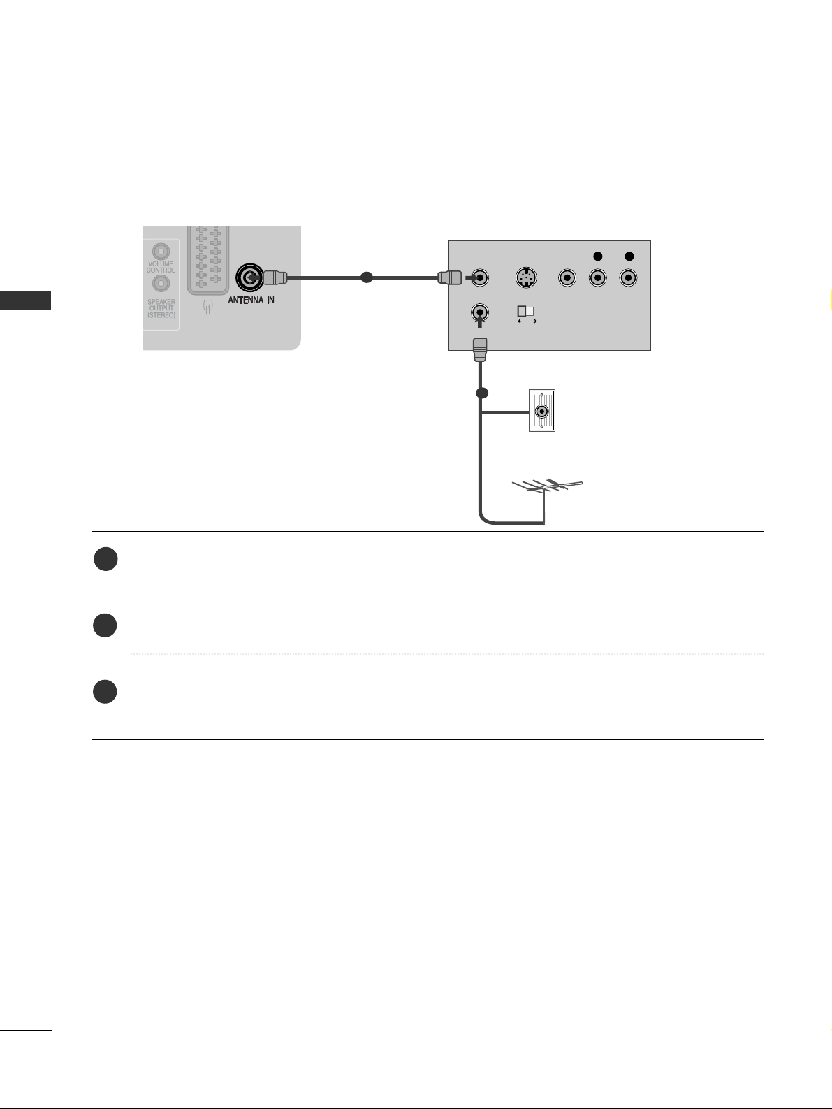
When connecting with a RF Cable
Connect the
AA NNTT OOUU TT
socket of the VCR to the
AA NNTTEENN NNAA IINN
socket on the TV.
Connect the antenna cable to the
AA NNTT IINN
socket of the VCR.
Press the PLAY button on the VCR and match the appropriate channel between the TV and VCR for view-
ing.
1
2
3
EXTERNAL EQUIPMENT SETUP
17
Connecting with a Euro Scart cable
Connect the Euro scart socket of the VCR to the
AA VV 11((RRGGBB))
Euro scart socket on the TV.
Insert a video tape into the VCR and press PLAY on
the VCR. (Refer to the VCR owner’s manual.)
Select
AAVV 11
input source using the
IINN PP UU TT
button on
the remote control.
2
3
1
NOTE
!
GG
Any Euro scart cable used must be signal shielded.
Connecting with a RCA cable
Connect the
AA UU DDIIOO/VV II DDEE OO
jacks between TV and
VCR. Match the jack colours (Video = yellow, Audio Left
= white, and Audio Right = red)
Insert a video tape into the VCR and press PLAY on
the VCR. (Refer to the VCR owner’s manual.
)
Select
AAVV 22
input source using the
IINN PP UU TT
button on
the remote control.
1
2
3
GG
If you have a mono VCR, connect the audio cable from the
VCR to the
AA UUDDII OO LL//MMOO NNOO
jack of the TV.
NOTE
!
(R) AUDIO (L)
AUDIO/
VIDEO
1
L
R
S-VIDEO
VIDEO
OUTPUT
SWITCH
ANT IN
ANT OUT
1
EXTERNAL EQUIPMENT SETUP
18
EXTERNAL EQUIPMENT SETUP
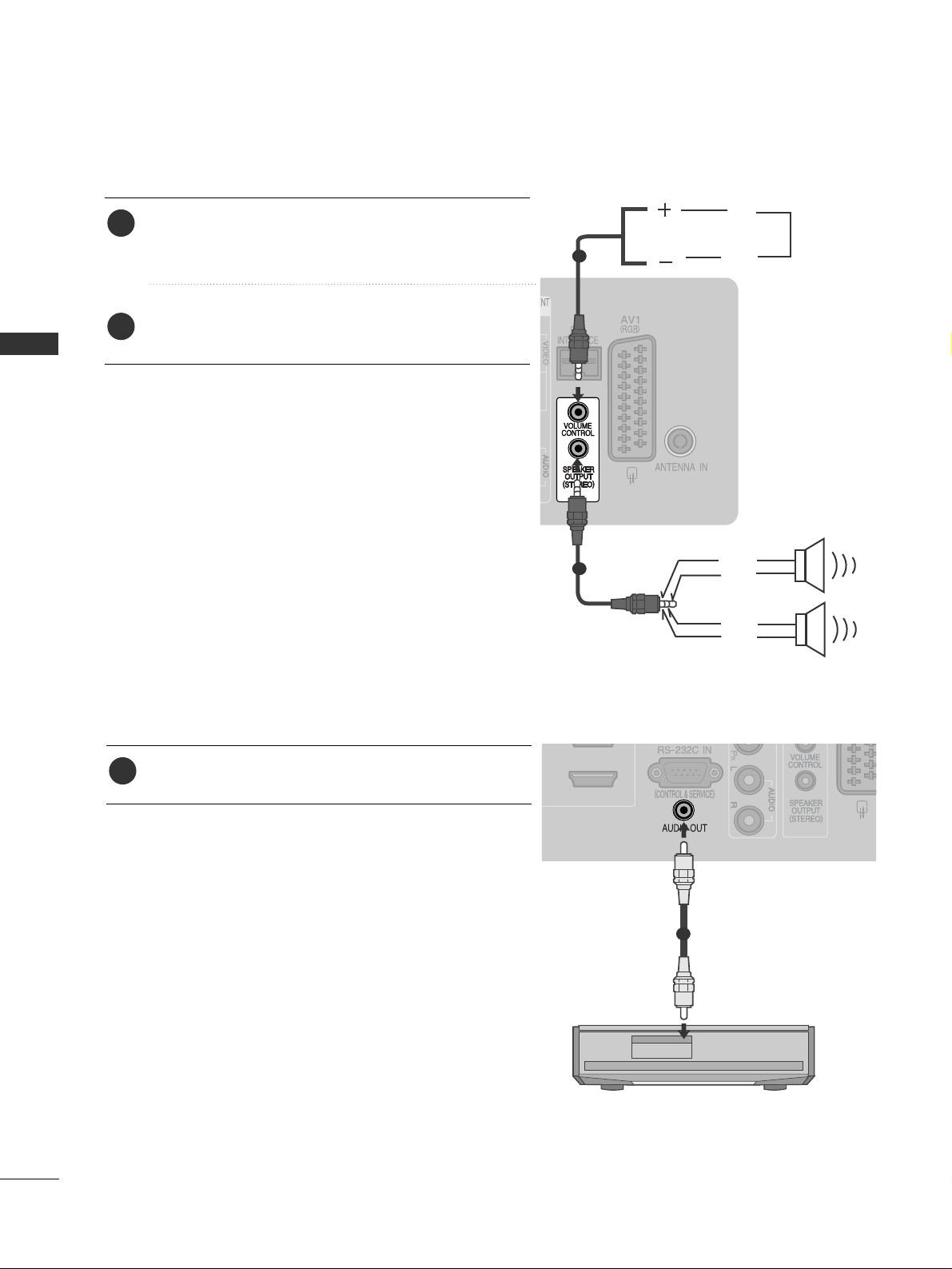
SPEAKER OUTPUT SETUP
Connect the external speaker to the
SS PP EEAAKKEERR
OOUUTTPPUUTT((SSTTEE RREEOO))
jack on the TV.
Refer to the “Installation Menu”.
2
1
LEFT
GND
UP
DOWN
Control port for Speaker out
RIGHT
GND
1
AUDIO OUT SETUP
1
Connect to the Home Theater.(or amp)
1
1
EXTERNAL EQUIPMENT SETUP
19
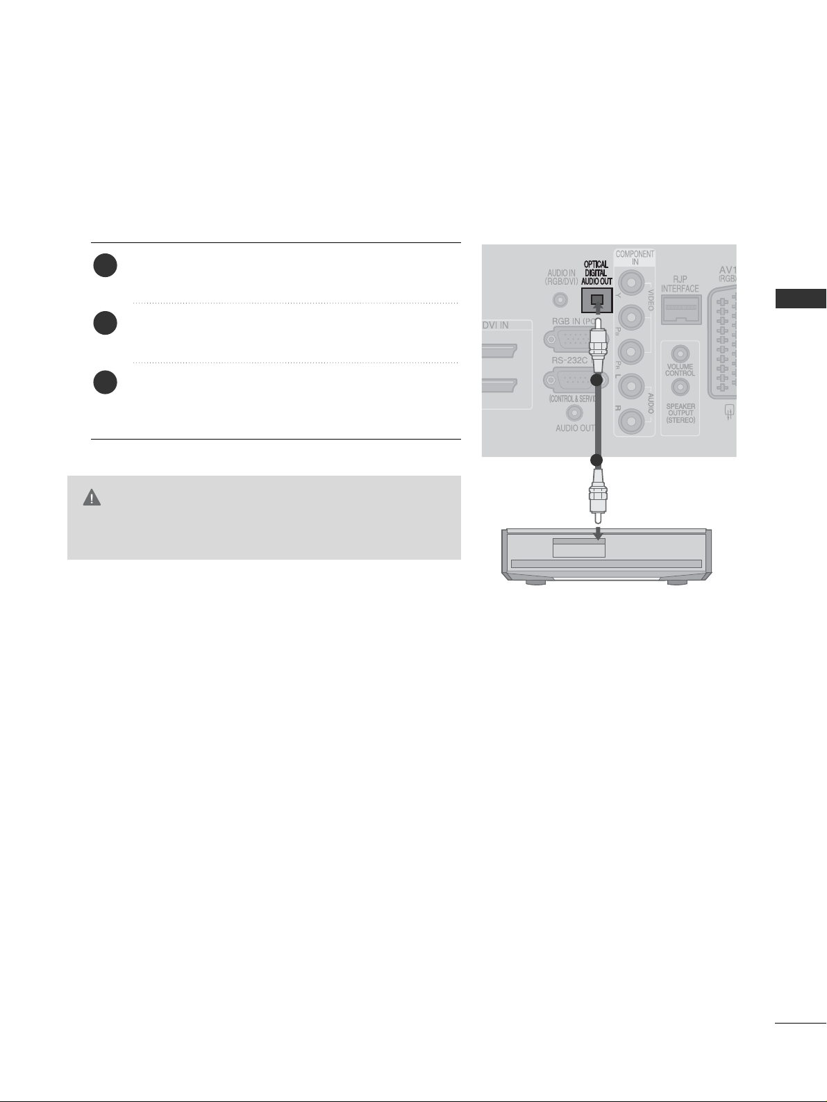
G
Do not look into the optical output port. Looking at the
laser beam may damage your vision.
CAUTION
Connect one end of an optical cable to the TV Digital
Audio (Optical)Output port.
Connect the other end of the optical cable to the digital audio (Optical)input on the audio equipment.
Refer to the external audio equipment instruction manual for operation.
2
3
1
1
2
DIGITAL AUDIO OUT SETUP
Sending the TV’s audio signal to external audio equipment via the Digital Audio Output (Optical) port.
If you want to enjoy digital broadcasting through 5.1-channel speakers, connect the OPTICAL DIGITAL
AUDIO OUT terminal on the back of TV to a Home Theater (or amp).
EXTERNAL EQUIPMENT SETUP
20
EXTERNAL EQUIPMENT SETUP
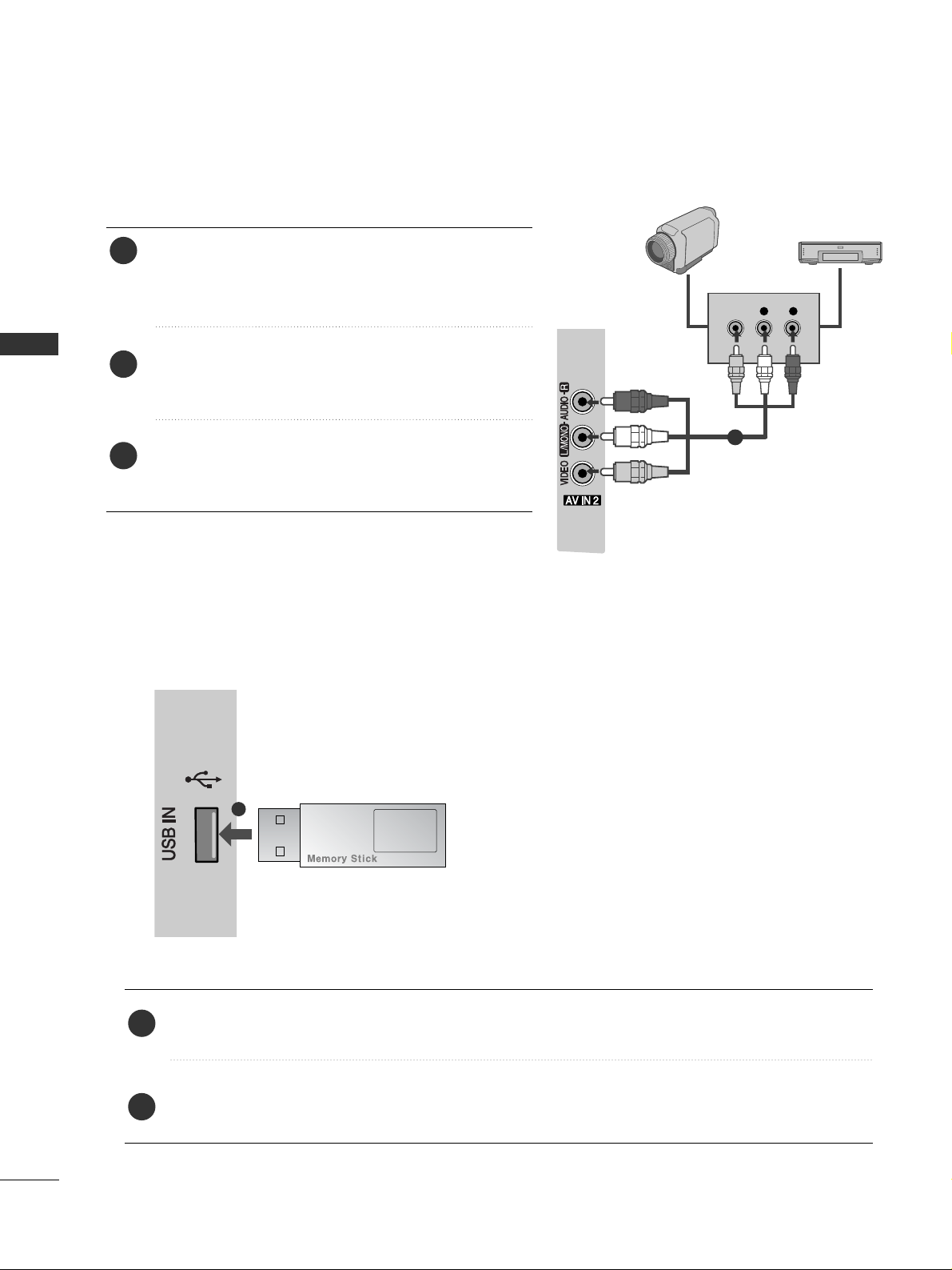
L R
VIDEO
Connect the
AA UU DDII OO/VV II DDEE OO
jacks between TV and
external equipment. Match the jack colours
. (Video =
yellow, Audio Left = white, and Audio Right = red
)
Select
AA VV22
input source using the
IINN PP UU TT
button on
the remote control.
Operate the corresponding external equipment.
Refer to external equipment operating guide.
2
3
1
Camcorder
Video Game Set
OTHER A/V SOURCE SETUP
11
USB IN SETUP
Connect the USB device to the
UUSSBB IINN
jack on the TV.
After connecting the
UUSSBB IINN
jacks, you use the
UU SS BB
function. (
GG
pp..4455
)
2
1
1
■
Here shown may differ from your TV.
EXTERNAL EQUIPMENT SETUP
21
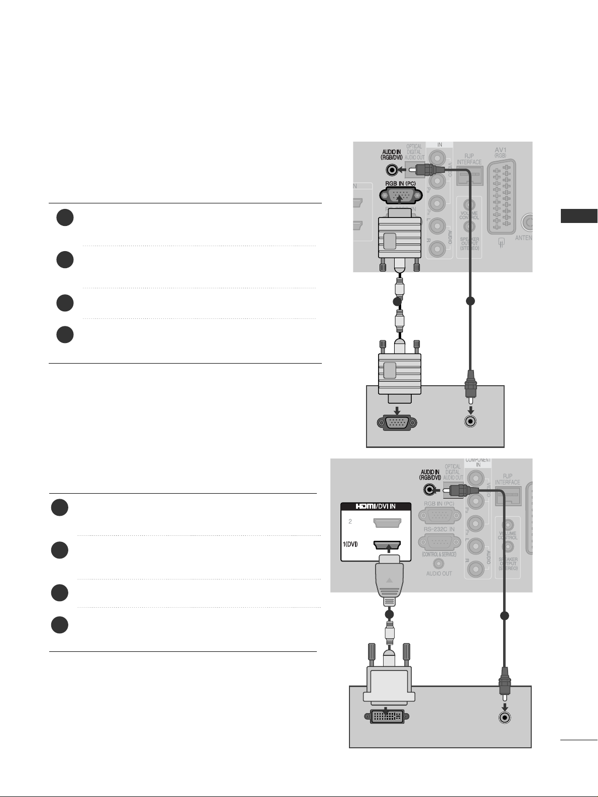
PC SETUP
This TV provides Plug and Play capability, meaning that the PC adjusts automatically to the TV's settings.
Connecting with a D-sub 15 pin cable
AUDIO
RGB OUTPUT
DVI-PC OUTPUT
AUDIO
1
2
4
Connect the RGB output of the PC to the
RRGG BB II NN
(( PP CC ))
jack on the TV.
Connect the PC audio output to the
AA UUDDII OO IINN
((RR GGBB // DDVVII))
jack on the TV.
Turn on the PC and the TV
Select
RRGG BB
input source using the INPUT button on
the remote control.
2
3
1
Connecting with a HDMI to DVI cable
Connect the DVI output of the PC to the
HHDD MMII//DD VV II IINN
11((DD VV II ))
jack on the TV.
Connect the PC audio output to the
AA UUDDII OO II NN
((RR GGBB//DD VV II))
jack on the TV.
Turn on the PC and the TV.
Select
HHDD MMII 11
input source using the
IINN PP UU TT
button
on the remote control.
2
3
4
1
1
2
EXTERNAL EQUIPMENT SETUP
22
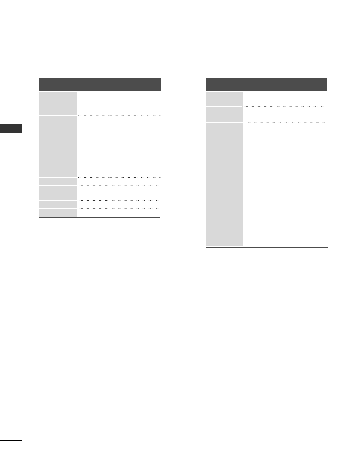
Supported Display Resolution
70.08
59.94
75.00
60.31
75.00
74.55
60.00
70.00
75.029
59.87
59.8
59.6
59.948
59.94
60.0
59.988
RGB[PC], HDMI[PC] mode
31.469
31.469
37.684
37.879
46.875
49.725
48.363
56.470
60.123
47.78
47.72
47.56
64.744
62.290
63.595
66.647
Resolution
640x480
800x600
832x624
720x400
1024x768
Horizontal
Frequency(kHz)
Vertical
Frequency(Hz)
1280x768
1360x768
1366x768
HDMI[DTV] mode
59.94
60
59.94
60.00
59.94
60.00
50.00
50
59.94
60.00
59.94
60.00
50.00
24.00
23.97
30.00
29.976
50.00
59.94
60.00
31.47
31.50
31.469
31.47
31.50
31.25
37.50 0
44.96
45.00
33.72
33.75
28.12
27.000
26.97
33.75
33.716
56.25
67.43
67.5
Resolution
640x480
720x480
720x576
1280x720
1920x1080
Horizontal
Frequency(kHz)
Vertical
Frequency(Hz)
EXTERNAL EQUIPMENT SETUP
1400x1050
1680x1050
1280x1024
1920x1080
720x480

EXTERNAL EQUIPMENT SETUP
23
NOTE
!
G
Avoid keeping a fixed image on the set’s screen
for prolonged periods of time. The fixed image
may become permanently imprinted on the
screen; use a screen saver when possible.
G
There may be interference relating to resolution,
vertical pattern, contrast or brightness in PC
mode. Change the PC mode to another resolution or change the refresh rate to another rate or
adjust the brightness and contrast on the menu
until the picture is clear. If the refresh rate of the
PC graphic card can not be changed, change the
PC graphic card or consult the manufacturer of
the PC graphic card.
G
The synchronization input waveform for
Horizontal and Vertical frequencies are separate.
G
We recommend using 1920x1080, 60Hz for the
PC mode, this should provide the best picture
quality.
G
Connect the signal cable from the monitor output port of the PC to the RGB (PC) port of the
TV or the signal cable from the HDMI output
port of the PC to the HDMI IN (or HDMI/DVI
IN) port on the TV.
G
Connect the audio cable from the PC to the
Audio input on the TV. (Audio cables are not
included with the TV).
G
If using a sound card, adjust PC sound as
required.
G
If required, adjust the settings for Plug and Play
functionality
G
If the graphic card on the PC does not output
analogue and digital RGB simultaneously, connect only one of either RGB or HDMI IN (or
HDMI/DVI IN) to display the PC output on the
TV.
G
If the graphic card on the PC does output analog and digital RGB simultaneously, set the TV to
either RGB or HDMI; (the other mode is set to
Plug and Play automatically by the TV.)
G
DOS mode may not work depending on the
video card if you use an HDMI to DVI cable.
G
If you use too long an RGB-PC cable that is too
long, there may be interference on the screen.
We recommend using under 5m of cable. This
provides the best picture quality.
EXTERNAL EQUIPMENT SETUP
24
EXTERNAL EQUIPMENT SETUP
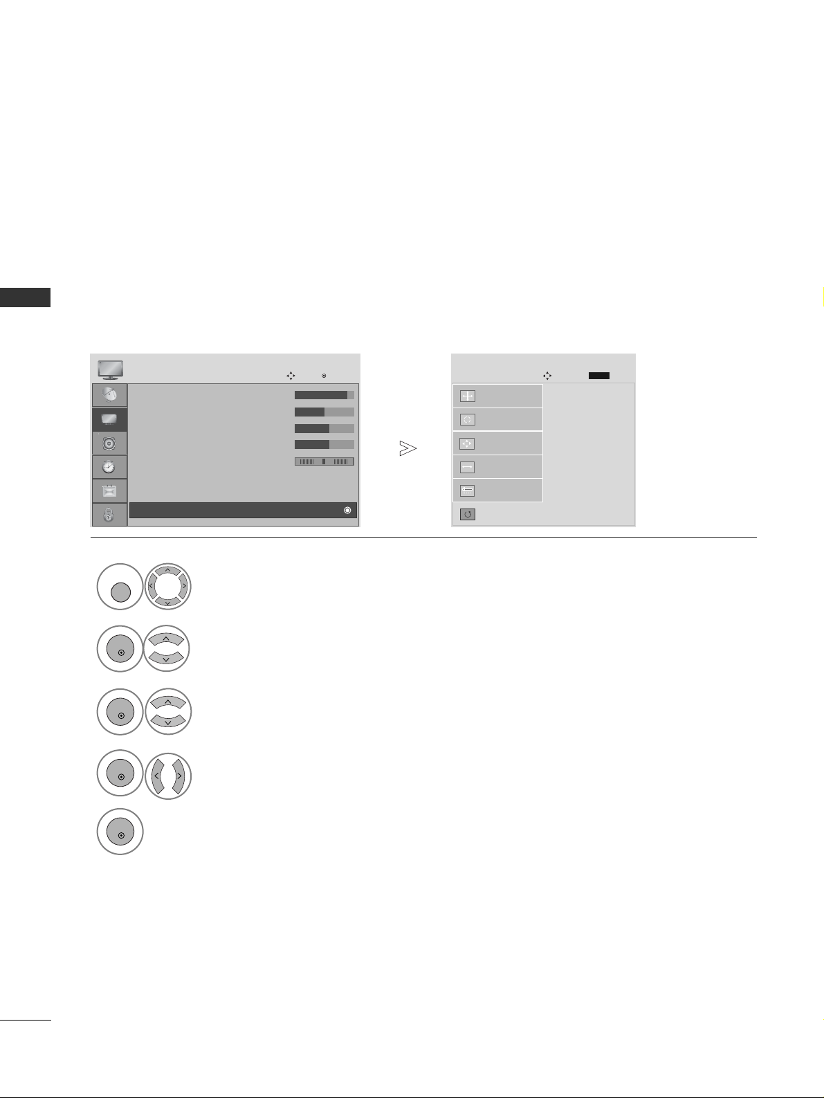
Screen Setup for PC mode
Returns to the default settings Position, Size and Phase at the factory.
This function works in the following mode : RGB[PC].
Screen Reset
• Contrast : 90
• Brightness : 50
• Sharpness : 60
• Colour : 60
• Tint : 0
• Advanced Control
• Picture Reset
PICTURE
Move
OK
D
Screen
To S e t
Auto Config.
SCREEN
Move
Prev.
RETURN
Resolution
Position
Size
Phase
Reset
G
1
MENU
Select
PP IICC TT UU RR EE
.
Select
SS cc rreeeenn
.
3
Select
RRee ssee tt
.
2
OK
OK
Select
YY ee ss
.
Run
RRee ssee tt
.
4
OK
5
OK
• Press the
MMEE NN UU
button to return to normal TV viewing.
• Press the
RREE TTUURRNN
button to move to the previous menu screen.
RG
EXTERNAL EQUIPMENT SETUP
25
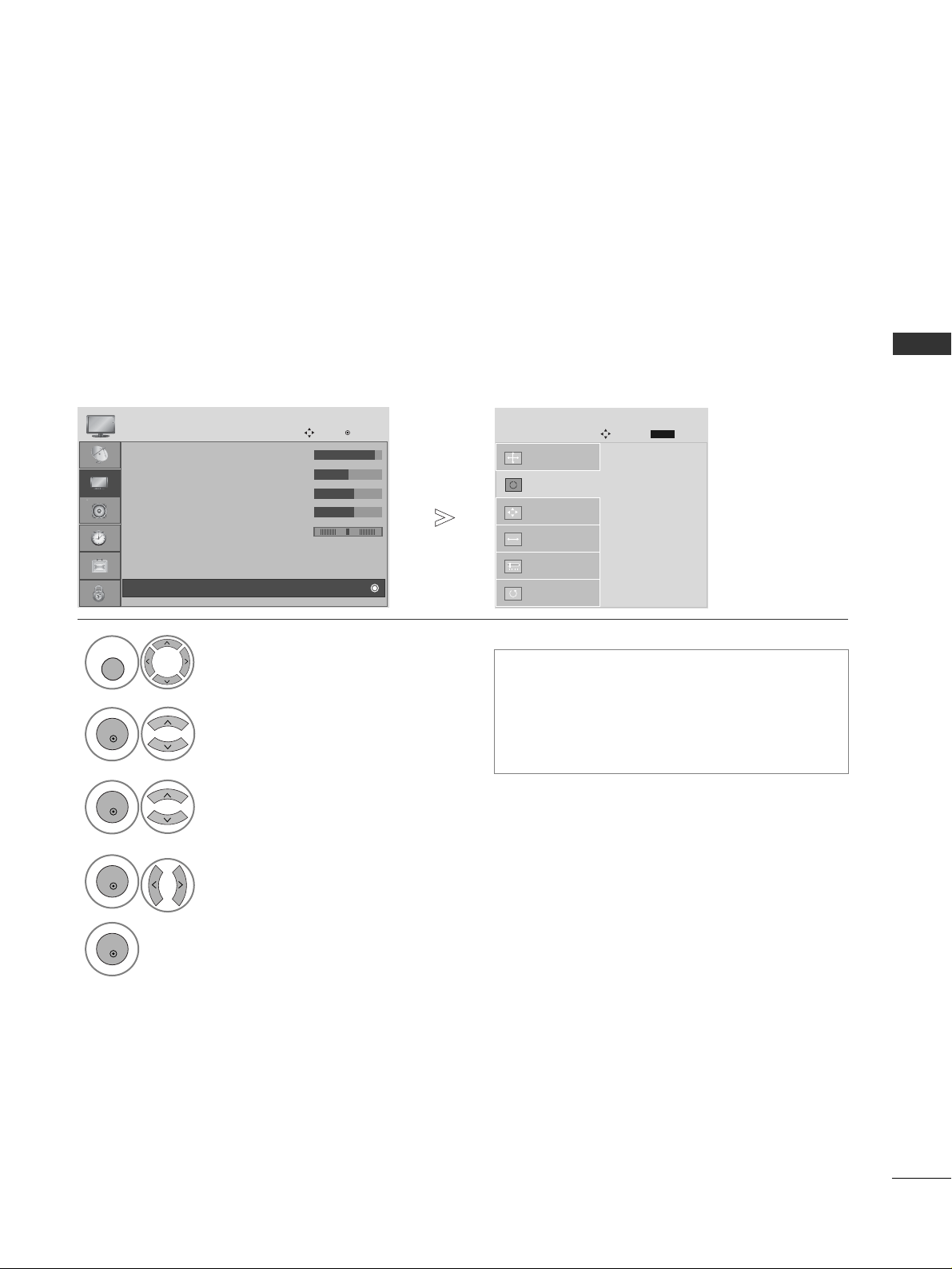
Automatically adjusts the picture position and minimizes image instability. After adjustment, if the image is
still not correct, your TV is functioning properly but needs further adjustment.
AAuuttoo ccoonnffiigguurr ee
This function is for automatic adjustment of the screen position, size, and phase The displayed image will be
unstable for a few seconds while the auto configuration is in progress.
Auto Configure (RGB [PC] mode only)
• If the position of the image is still not correct,
try Auto adjustment again.
• If picture needs to be adjusted again after Auto
adjustment in RGB (PC), you can adjust the
PP ooss ii ttiioo nn, SS ii zz ee
or
PP hh aa ssee
.
To S e t
Auto Config.
G
SCREEN
Move
Resolution
Position
Size
Phase
Reset
Prev.
RETURN
Select
PP IICC TT UU RR EE
.
Select
SS cc rree ee nn
.
Select
AA uu ttoo CC oonnffiigg ..
.
1
MENU
3
2
OK
OK
Select
YY ee ss
.
Run
AA uu ttoo CC oonnffiigg ..
.
4
OK
5
OK
• Press the
MMEE NN UU
button to return to normal TV viewing.
• Press the
RREE TTUURRNN
button to move to the previous menu screen.
• Contrast : 90
• Brightness : 50
• Sharpness : 60
• Colour : 60
• Tint : 0
• Advanced Control
• Picture Reset
PICTURE
Move
OK
D
Screen
RG
EXTERNAL EQUIPMENT SETUP
26
EXTERNAL EQUIPMENT SETUP
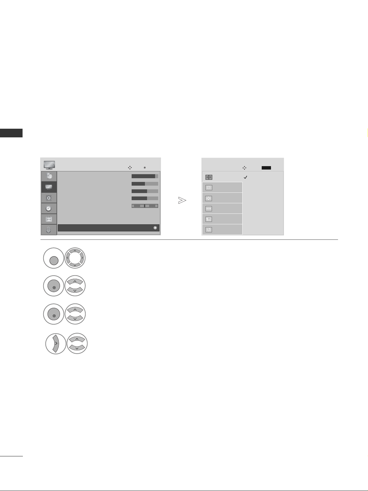
To view a normal picture, match the resolution of RGB mode and selection of PC mode.
This function works in the following mode: RGB[PC] mode.
Selecting Resolution
1024 x 768
128 0 x 7 6 8
136 0 x 7 6 8
136 6 x 7 6 8
Auto Config.
SCREEN
Move
Resolution
G
Position
Size
Phase
Reset
Prev.
RETURN
Select
PP IICC TT UU RR EE
.
Select
SS cc rree ee nn
.
Select
RRee ssoolluu tt ii oonn
.
Select the desired resolution.
1
MENU
3
4
2
OK
OK
• Press the
MMEE NN UU
button to return to normal TV viewing.
• Press the
RREE TTUURRNN
button to move to the previous menu screen.
• Contrast : 90
• Brightness : 50
• Sharpness : 60
• Colour : 60
• Tint : 0
• Advanced Control
• Picture Reset
PICTURE
Move
OK
D
Screen
RG
EXTERNAL EQUIPMENT SETUP
27
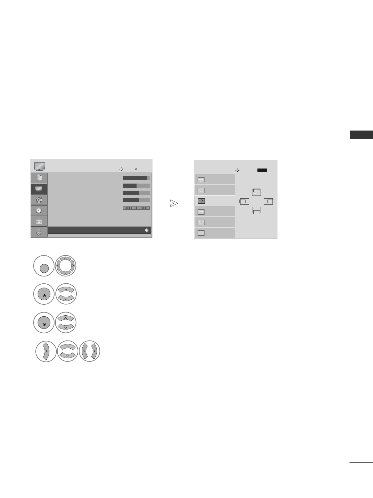
If the picture is not clear after auto adjustment and especially if characters are still trembling, adjust the
picture phase manually.
This function works in the following mode : RGB[PC].
Adjustment for screen Position, Size, Phase
Auto Config.
SCREEN
Move
Resolution
Position
G
Size
Phase
Reset
GF
D
E
Prev.
RETURN
Select
PP IICC TT UU RR EE
.
Select
SS cc rree ee nn
.
Select
PP ooss ii ttiioo nn, SS ii zz ee
or
PP hh aa ssee
.
Make appropriate adjustments.
1
MENU
3
4
2
OK
OK
• Press the
MMEE NN UU
button to return to normal TV viewing.
• Press the
RREE TTUURRNN
button to move to the previous menu screen.
• Contrast : 90
• Brightness : 50
• Sharpness : 60
• Colour : 60
• Tint : 0
• Advanced Control
• Picture Reset
PICTURE
Move
OK
D
Screen
RG
WATCHING TV / PROGRAMME CONTROL
28
WATCHING TV / PROGRAMME CONTROL
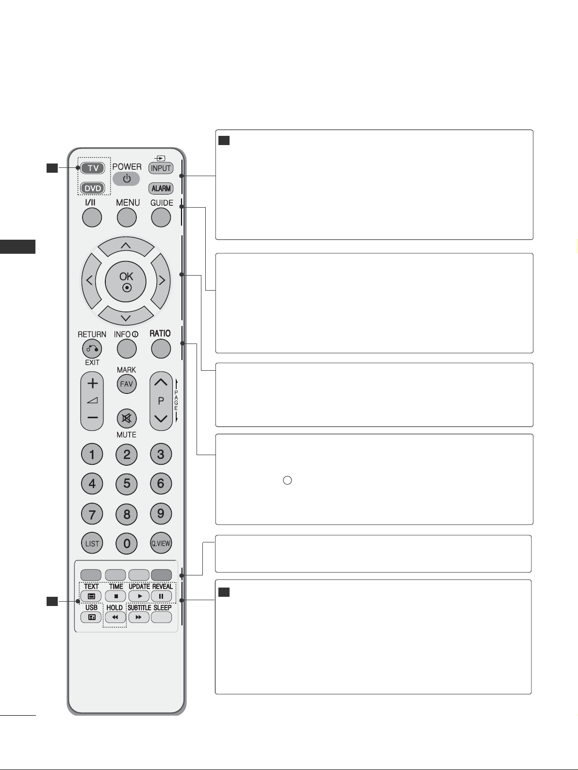
REMOTE CONTROL KEY FUNCTIONS
When using the remote control, aim it at the remote control sensor on the TV.
MODE
POWER
INPUT
ALARM
Selects the remote operating modes.
Switches the TV on from standby or off to standby.
External input mode rotate in regular sequence.
Switches the TV on from standby.
Sets the alarm function.
I/II
MENU
GUIDE
Selects the sound output.
Selects a menu.
Clears all on-screen displays and returns to TV viewing
from any menu.(
GG
pp ..3311
)
Shows programme schedule.(
GG
pp ..5533
)
THUMBSTICK
(Up/Down/Left
Right)
OK
Allows you to navigate the on-screen menus and adjust
the system settings to your preference.
Accepts your selection or displays the current mode.
RETURN(EXIT)
INFO i
RATIO
Allows the user to move return one step in an interactive application, EPG or other user interaction function.
Shows the present screen information.
Selects your desired picture format.(
GG
pp ..5555
)
Coloured
buttons
These buttons are used for teletext (on
TT EELLEETTEEXX TT
models only) or
PP rroogg rraa mm mmee ee ddiitt
.
TELETEXT
BUTTONS
USB
SUBTITLE
SLEEP
These buttons are used for teletext.
For further details, see the ‘Teletext’ section.(
GG
pp ..8822
)
Enter to the USB mode.
Recalls your preferred subtitle in digital mode.
Sets the sleep timer.
1
1
2
2
 Loading...