

Page 1

OWNER’S MANUAL
LCD TV
Please read this manual carefully before operating
your set and retain it for future reference.
22LG3DDH
26LG3DDH
32LG3DDH
42LD6DDH
P/NO : SAC34026007 (1110-REV07)
www.lg.com
Page 2

WARNING / CAUTION
WARNING/CAUTION
RISK OF ELECTRIC SHOCK
DO NOT OPEN
WARNING / CAUTION
WARNING/CAUTION
RISK OF ELECTRIC SHOCK
DO NOT OPEN
TO REDUCE THE RISK OF ELECTRIC SHOCK
DO NOT REMOVE COVER (OR BACK).
NO USER SERVICEABLE PARTS INSIDE.
REFER TO QUALIFIED SERVICE PERSONNEL.
The lightning flash with arrowhead
symbol, within an equilateral triangle, is
intended to alert the user to the presence of
uninsulated “dangerous voltage” within the
product’s enclosure that may be of sufficient
magnitude to constitute a risk of electric shock
to persons.
The exclamation point within an
equilateral triangle is intended to alert
the user to the presence of important operating
and maintenance (servicing) instructions in the
literature accompanying the appliance.
WARNING/CAUTION
TO REDUCE THE RISK OF FIRE AND ELECTRIC
SHOCK, DO NOT EXPOSE THIS PRODUCT TO
RAIN OR MOISTURE.
To prevent fire or shock hazards, do not expose this
product to rain or moisture.
FCC NOTICE
Class B digital device
This equipment has been tested and found to comply
with the limits for a Class B digital device, pursuant to
Part 15 of the FCC Rules. These limits are designed to
provide reasonable protection against harmful
interference in a residential installation. This
equipment generates, uses and can radiate radio
frequency energy and, if not installed and used in
accordance with the instructions, may cause harmful
interference to radio communications. However, there
is no guarantee that interference will not occur in a
particular installation. If this equipment does cause
harmful interference to radio or television reception,
which can be determined by turning the equipment off
and on, the user is encouraged to try to correct the
interference by one or more of the following measures:
- Reorient or relocate the receiving antenna.
- Increase the separation between the equipment and
receiver.
- Connect the equipment to an outlet on a circuit
different from that to which the receiver is
connected.
- Consult the dealer or an experienced radio/TV
technician for help.
Any changes or modifications expressly approved
by the party responsible for compliance could void
the user’s authority to operate the equipment.
NOTE TO CABLE/TV INSTALLER
This reminder is provided to call the CATV system
installer’s attention to Article 820-40 of the
National Electric Code (U.S.A.). The code provides
guidelines for proper grounding and, in particular,
specifies that the cable ground shall be connected
to the grounding system of the building, as close to
the point of the cable entry as practical.
CAUTION
Do not attempt to modify this product in any way
without written authorization from LG Electronics.
Unauthorized modification could void the user’s
authority to operate this product
1
Page 3

Short-circuit
Breaker
Short-circuit
Breaker
Antenna Lead in Wire
Antenna Discharge Unit
(NEC Section 810-20)
Grounding Conductor
(NEC Section 810-21)
Ground Clamps
Power Service Grounding
Electrode System (NEC
Art 250, Part H)
Ground Clamp
Electric Service
Equipment
NEC: National Electrical Code
Antenna Lead in Wire
Antenna Discharge Unit
(NEC Section 810-20)
Grounding Conductor
(NEC Section 810-21)
Ground Clamps
Power Service Grounding
Electrode System (NEC
Art 250, Part H)
Ground Clamp
Electric Service
Equipment
NEC: National Electrical Code
Ground Clamp
Electric Service
Equipment
Short-circuit
Breaker
Power
Supply
NEC: National Electrical Code
Ground Clamp
Electric Service
Equipment
Short-circuit
Breaker
Power
Supply
NEC: National Electrical Code
SAFETY INSTRUCTIONS
IMPORTANT SAFETY INSTRUCTIONS
Read these instructions.
Keep these instructions.
Heed all warnings.
Follow all instructions.
Do not use this apparatus near water.
1
Clean only with a dry cloth.
2
Do not block any ventilation openings. Install in
3
accordance with the manufacturer’s instructions.
Protect the power cord from being walked on or
6
pinched particularly at plugs, convenience
receptacles, and the point where they exit from
the apparatus.
Only use attachments/accessories specified by
7
the manufacturer.
Use only with the cart, stand, tripod, bracket, or
8
table specified by the manufacturer, or sold with
the apparatus. When a cart is used, use caution
when moving the cart/apparatus combination to
avoid injury from tip-over.
Do not install near any heat sources such as
4
radiators, heat registers, stoves, or other
apparatus (including amplifiers)that produce
heat.
Do not defeat the safety purpose of the
5
polarized or grounding-type plug. A polarized
plug has two blades with one wider than the
other. A grounding type plug has two blades and
a third grounding prong, The wide blade or the
third prong are provided for your safety. If the
provided plug does not fit into your outlet,
consult an electrician for replacement of the
obsolete outlet.
2
Unplug this apparatus during lighting storms or
9
when unused for long periods of time.
Refer all servicing to qualified service personnel.
10
Servicing is required when the apparatus has
been damaged in any way, such as power-supply
cord or plug is damaged, liquid has been spilled
or objects have fallen into the apparatus, the
apparatus has been exposed to rain or moisture,
does not operate normally, or has been dropped.
Page 4
Antenna Lead in Wire
Antenna Discharge Unit
(NEC Section 810-20)
Grounding Conductor
(NEC Section 810-21)
Ground Clamps
Power Service Grounding
Electrode System (NEC
Art 250, Part H)
Ground Clamp
Electric Service
Equipment
NEC: National Electrical Code
Antenna Lead in Wire
Antenna Discharge Unit
(NEC Section 810-20)
Grounding Conductor
(NEC Section 810-21)
Ground Clamps
Power Service Grounding
Electrode System (NEC
Art 250, Part H)
Ground Clamp
Electric Service
Equipment
NEC: National Electrical Code
Antenna Lead in Wire
Antenna Discharge Unit
(NEC Section 810-20)
Grounding Conductor
(NEC Section 810-21)
Ground Clamps
Power Service Grounding
Electrode System (NEC
Art 250, Part H)
Ground Clamp
Electric Service
Equipment
Short-circuit
Breaker
Power
Supply
NEC: National Electrical Code
Never touch this apparatus or antenna during
11
a thunder or lighting storm.
When mounting a TV on the wall, make sure
12
not to install the TV by the hanging power and
signal cables on the back of the TV.
Do not allow an impact shock or any objects to
13
fall into the product, and do not drop onto the
screen with something.
CAUTION concerning the Power Cord :
14
It is recommend that appliances be placed
upon a dedicated circuit; that is, a single outlet
circuit which powers only that appliance and
has no additional outlets or branch circuits.
Check the specification page of this owner's
manual to be certain.
Do not connect too many appliances to the
same AC power outlet as this could result in
fire or electric shock.
Do not overload wall outlets. Overloaded wall
outlets, loose or damaged wall outlets,
extension cords, frayed power cords, or
damaged or cracked wire insulation are
dangerous. Any of these conditions could
result in electric shock or fire. Periodically
examine the cord of your appliance, and if its
appearance indicates damage or deterioration,
unplug it, discontinue use of the appliance, and
have the cord replaced with an exact
replacement part by an authorized servicer.
Protect the power cord from physical or
mechanical abuse, such as being twisted,
kinked, pinched, closed in a door, or walked
upon. Pay particular attention to plugs, wall
outlets, and the point where the cord exits the
appliance.
Do not make the TV with the power cord
plugged in. Do not use a damaged or loose
power cord. Be sure do grasp the plug when
unplugging the power cord. Do not pull on the
power cord to unplug the TV.
WARNING - To reduce the risk of fire or
15
electrical shock, do not expose this product to
rain, moisture or other liquids. Do not touch
the TV with wet hands. Do not install this
product near flammable objects such as
gasoline or candles or expose the TV to direct
air conditioning.
Do not expose to dripping or splashing and do
16
not place objects filled with liquids, such as
vases, cups, etc. on or over the apparatus (e.g.
on shelves above the unit).
GROUNDING
17
Ensure that you connect the earth ground wire
to prevent possible electric shock. (i.e. a TV
with a three-prong grounded AC plug must be
connected to a three-prong grouned AC
outlet) If grounding methods are not possible,
have a qualified electrician install a separate
circuit breaker.
Do not try to ground the unit by connecting it
to telephone wires, lightening rods, or gas
pipes.
DISCONNECTING DEVICE FROM MAINS
18
Mains plug is the disconnecting device. The
plug must remain readily operable.
Keep the product away from direct sunlight.
19
3
Page 5

ANTENNAS
Antenna Lead in Wire
Antenna Discharge Unit
(NEC Section 810-20)
Grounding Conductor
(NEC Section 810-21)
Ground Clamps
Power Service Grounding
Electrode System (NEC
Art 250, Part H)
Ground Clamp
Electric Service
Equipment
NEC: National Electrical Code
Antenna Lead in Wire
Antenna Discharge Unit
(NEC Section 810-20)
Grounding Conductor
(NEC Section 810-21)
Ground Clamps
Power Service Grounding
Electrode System (NEC
Art 250, Part H)
Ground Clamp
Equipment
NEC: National Electrical Code
20
Outdoor antenna grounding
If an outdoor antenna is installed, follow the
precautions below. An outdoor antenna system
should not be located in the vicinity of
overhead power lines or other electric light or
power circuits, or where it can come in contact
with such power lines or circuits as death or
serious injury can occur.
Be sure the antenna system is grounded so as
to provide some protection against voltage
surges and built-up static charges.
Section 810 of the National Electrical Code
(NEC) in the U.S.A. provides information with
respect to proper grounding of the mast and
supporting structure, grounding of the lead-in
wire to an antenna discharge unit, size of
grounding conductors, location of antenna
discharge unit, connection to grounding
electrodes and requirements for the grounding
electrode.
Antenna grounding according to the
National Electrical Code, ANSI/NFPA 70
Ventilation
23
Install your TV where there is proper
ventilation. Do not install in a confined space
such as a bookcase. Do not cover the product
with cloth or other materials (e.g.) plastic while
plugged in. Do not install in excessively dusty
places.
Take care not to touch the ventilation
24
openings. When watching the TV for a long
period, the ventilation openings may become
hot.
If you smell smoke or other odors coming from
25
the TV or hear strange sounds, unplug the
power cord contact and authorized service
center.
Do not press strongly upon the panel with a
26
hand or sharp object such as nail, pencil or pen,
or make a scratch on it.
Cleaning
21
When cleaning, unplug the power cord and
Moving
22
Make sure the product is turned off, unplugged
4
scrub gently with a soft cloth to prevent
scratching. Do not spray water or other liquids
directly on the TV as electric shock may occur.
Do not clean with chemicals such as alcohol,
thinners or benzene.
and all cables have been removed. It may take
2 or more people to carry larger TVs. Do not
press against or put stress on the front panel
of the TV.
Keep the product away from direct sunlight.
27
For LCD TV
28
If the TV feels cold to the touch, there may be
a small “flicker” when it is turned on. This is
normal, there is nothing wrong with TV.
Some minute dot defects may be visible on the
screen, appearing as tiny red, green, or blue
spots. However, they have no adverse effect on
the monitor's performance.
Avoid touching the LCD screen or holding your
finger(s) against it for long periods of time.
Doing so may produce some temporary
distortion effects on the screen.
ON DISPOSAL
(Only Hg lamp used LCD TV)
The fluorescent lamp used in this product
contains a small amount of mercury. Do not
dispose of this product with general household
waste. Disposal of this product must be carried
out in accordance to the regulations of your local
authority.
Page 6

CONTENTS
WARNING / CAUTION 1
SAFETY INSTRUCTIONS 2
FEATURES OF THIS TV 6
PREPARATION
Accessories 7
Front Panel Information
Back Panel Information
Protection Cover
Cable Management
Desktop Pedestal Installation 13
Kensington Security System 13
VESA Wall Mounting
Securing the TV to the wall to prevent falling
When the TV is used on a stand
Antenna or Cable Connection
8
9
11
12
14
15
16
EXTERNAL EQUIPMENT SETUP
HD Receiver Setup 17
DVD Setup
VCR Setup
Other A/V Source Setup 24
Pillow Speaker Setup
PC Setup 26
20
22
25
WATCHING TV / CHANNEL CONTROL
Turning On TV 32
Channel Selection 32
Volume Adjustment
Initial Setting 33
On-Screen Menus Selection
Channel Setup
- Auto Scan (Auto Tuning)
- Add / Delete Channel (Manual Tuning)
- Channel Editing
Channel Label 39
Input List
40
32
35
36
37
38
PICTURE CONTROL
SOUND & LANGUAGE CONTROL
Auto Volume Leveler (Auto Volume) 49
Clear Voice II
Balance
Preset Sound Settings (Sound Mode) 52
Sound Setting Adjustment - User Mode 53
Infinite Sound
TV Speakers On/Off Setup 55
Audio Reset
Stereo/SAP Broadcast Setup
Audio Language
On-Screen Menus Language Selection
Caption Mode
- Analog Broadcasting System Captions
- Digital Broadcasting System Captions
- Caption Option 62
50
51
54
56
57
58
59
60
61
TIME SETTING
Clock Setting
- Auto Clock Setup
- Manual Clock Setup 64
Auto On/Off Time Setting 65
Sleep Timer Setting
Auto Shut-Off Setting 66
63
66
PARENTAL CONTROL / RATINGS
Set Password & Lock System 67
Channel Blocking
Movie & TV Rating
Downloadable Rating 74
External Input Blocking
70
71
75
APPENDIX
Troubleshooting 76
Maintenance
Product Specifications 79
Open Source License 80
77
Picture Size (Aspect Ratio) Control 41
Preset Picture Settings
Manual Picture Adjustment - User Mode
Picture Improvement Technology
Picture Reset
Demo Mode 48
47
43
44
45
5
Page 7

FEATURES OF THIS TV
USB IN
SERVUCE ONLY
USB IN
SERVUCE ONLY
HDMITM, the HDMI logo and High-Definition
Multimedia Interface are trademarks or registered
trademarks of HDMI Licensing LCC."
USB port shall be used for software update by
service personnel only.
Manufactured under license from Dolby
Laboratories. “Dolby “and the double-D symbol are
trademarks of Dolby Laboratories.
6
IMPORTANT INFORMATION TO PREVENT
“IMAGE BURN / BURN-IN” ON YOUR TV SCREEN
V When a fixed image (e.g. logos, screen menus, video game, and computer display) is displayed on the TV for
an extended period, it can become permanently imprinted on the screen. This phenomenon is known as
“image burn” or “burn-in.” Image burn is not covered under the manufacturer’s warranty.
V In order to prevent image burn, avoid displaying a fixed image on your TV screen for a prolonged period (2
or more hours for LCD, 1 or more hours for Plasma).
V Image burn can also occur on the letterboxed areas of your TV if you use the 4:3 aspect ratio setting for an
extended period.
Page 8

PREPARATION
ACCESSORIES
Ensure that the following accessories are included with your TV. If an accessory is missing, please contact the
dealer where you purchased the TV.
The accessories included may differ from the images below.
Owner’s Manual CD Manual Power cord Protective bracket and Bolt
for power cord
(Refer to P.12)
(This feature is not available for all models.)
PREPARATION
Optional Extras
* Wipe spots on the exterior
only with the polishing cloth.
* Do not wipe roughly when
Polishing Cloth
(This feature is not
available for all models.)
For 22LG3DDH
Optional Installer Remote Control for Model No. Series 22/26/32LG3DDH, 42LD6DDH
Cable Management Clip
(Refer to P.12)
removing stains. Excessive
pressure may cause
scratches or discoloration.
D-sub 15-pin cable
For 26/32LG3DDH, 42LD6DDH
When using the VGA (D-sub 15-pin
signal cable) PC connection, the
user must use shielded signal
interface cables with ferrite cores
to maintain standards compliance.
Protection Cover
(Refer to P.11)
There is an optional Installer remote control available for the 22/26/32LG3DDH, 42LD6DDH models.
The installer remote control is NOT included with the TV.
7
Page 9

PREPARATION
CH
VOL
MENU
INPUT
ENTER
CH
VOL
MENU
INPUT
ENTER
CH
VOL
MENU
INPUT
ENTER
CH
VOL
MENU
INPUT
ENTER
CH
VOL
ENTER
INPUT
MENU
CH
VOL
ENTER
INPUT
MENU
CH
VOL
ENTER
INPUT
MENU
!
FRONT PANEL INFORMATION
V Image shown may differ from your TV.
V
NOTE: If your TV has a protection tape attached, remove the tape. And then wipe the TV with a cloth(If a polishing cloth is included with your TV, use it).
PREPARATION
For 22/26/32LG3DDH
22LG3DDH
Headphone
Power/Standby Indicator
Illuminates green when the set is switched on.
Remote Control Sensor
POWER Button
CHANNEL(+, -)
Buttons
VOLUME (+, -)
Buttons
26/32LG3DDH
POWER Button
For 42LD6DDH
Remote Control Sensor
Power/Standby Indicator
Illuminates green when the set is switched on.
Remote Control Sensor
SPEAKER
Power/Standby Indicator
Illuminates red in standby mode.
Illuminates blue when the set is switched on.
ENTER Button
MENU Button
INPUT Button
CHANNEL(
Buttons
VOLUME (+, -)
Buttons
ENTER Button
MENU Button
INPUT Button
,
)
8
NOTE
G If Installer menu item 027(HOSPITAL MODE) is set value 254(Default), standby indicator does not illuminate.
POWER Button
Page 10
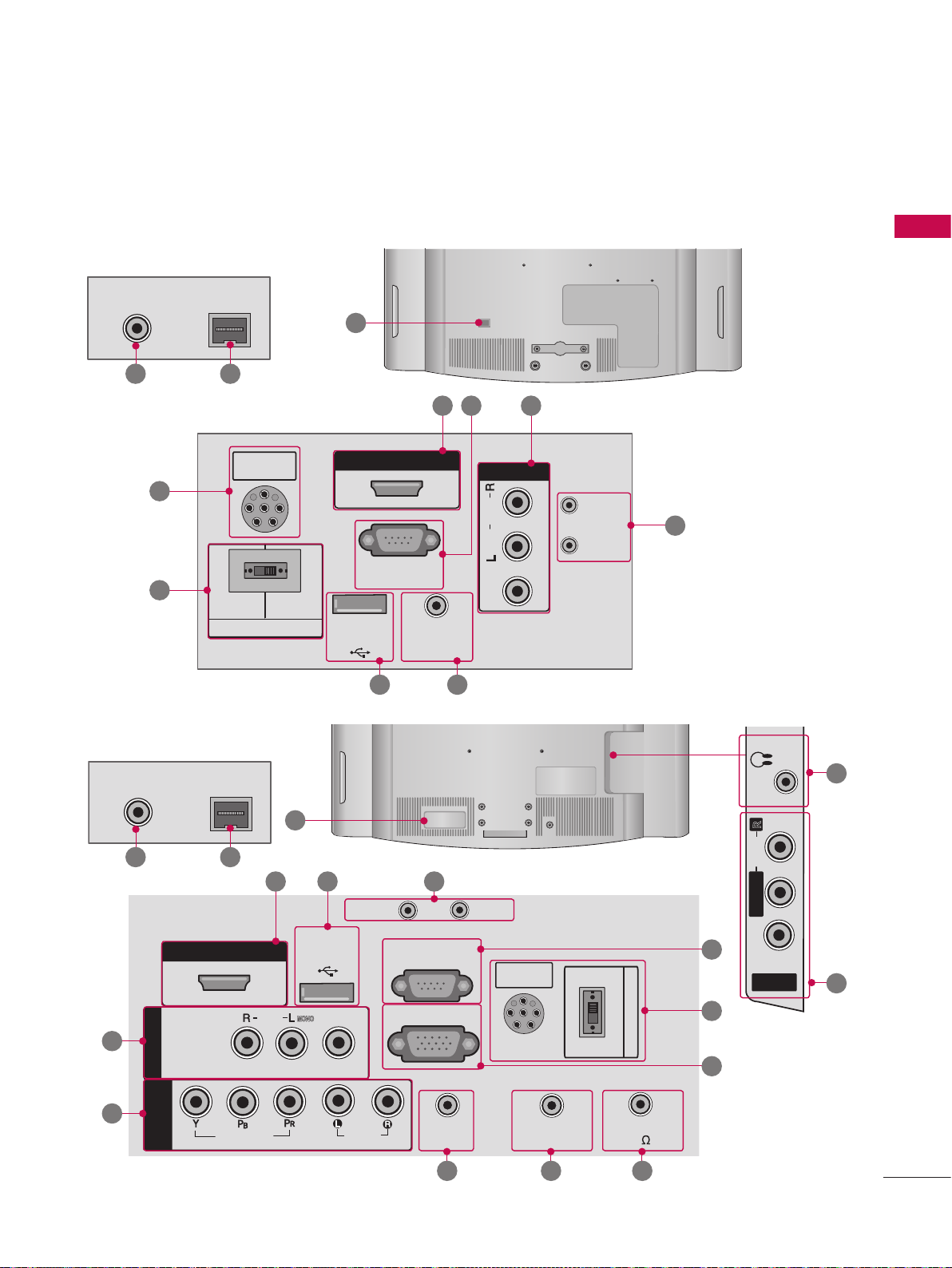
BACK PANEL INFORMATION
R
AUDIO
H/P
M.P.I.
AV IN 2
L/MONO
R
AUDIO
VIDEO
H/P
V Image shown may differ from your TV.
For 22LG3DDH
ANTENNA IN
13 14
15
15
M.P.I.
PILLOW
SPEAKER
PILLOW
SPEAKER
SPEAKER SWITCH
NORMAL
SPEAKER
12
HDMI/DVI IN
RS-232C IN
(SERVICE ONLY)
USB IN
SERVUCE ONLY
.2 .1
REMOTE
CONTROL OUT
.9.3
PREPARATION
.5
AV IN
AUDIO
MONO
( )
VIDEO
RESET
UPDATE
DVI AUDIO IN
.4
For 26/32LG3DDH
ANTENNA IN
13 14
.1
AV IN 1
.7
COMPONENT
M.P.I.
HDMI/DVI IN
IN
VIDEO
AUDIO
12
USB IN
SERVUCE ONLY
( )
MONO
VIDEO
UPDATE
AUDIO
.4.3.2
RESET
PILLOW
SPEAKER
RS-232C IN
(SERVICE ONLY)
RGB IN (PC)
AUDIO IN
(RGB/DVI)
.8 .9 10
REMOTE
CONTROL OUT
NORMAL
SPEAKER
PILLOW
SPEAKER
SPEAKER SWITCH
SPEAKER OUT
8
15
11
H/P
R
AUDIO
L/MONO
.5
.6
VIDEO
AV IN 2
.1
9
Page 11
PREPARATION
H/P
USB IN
SERVICE ONLY
AV IN 2
L/MONO
R
AUDIO
VIDEO
H/P
USB IN
SERVICE ONLY
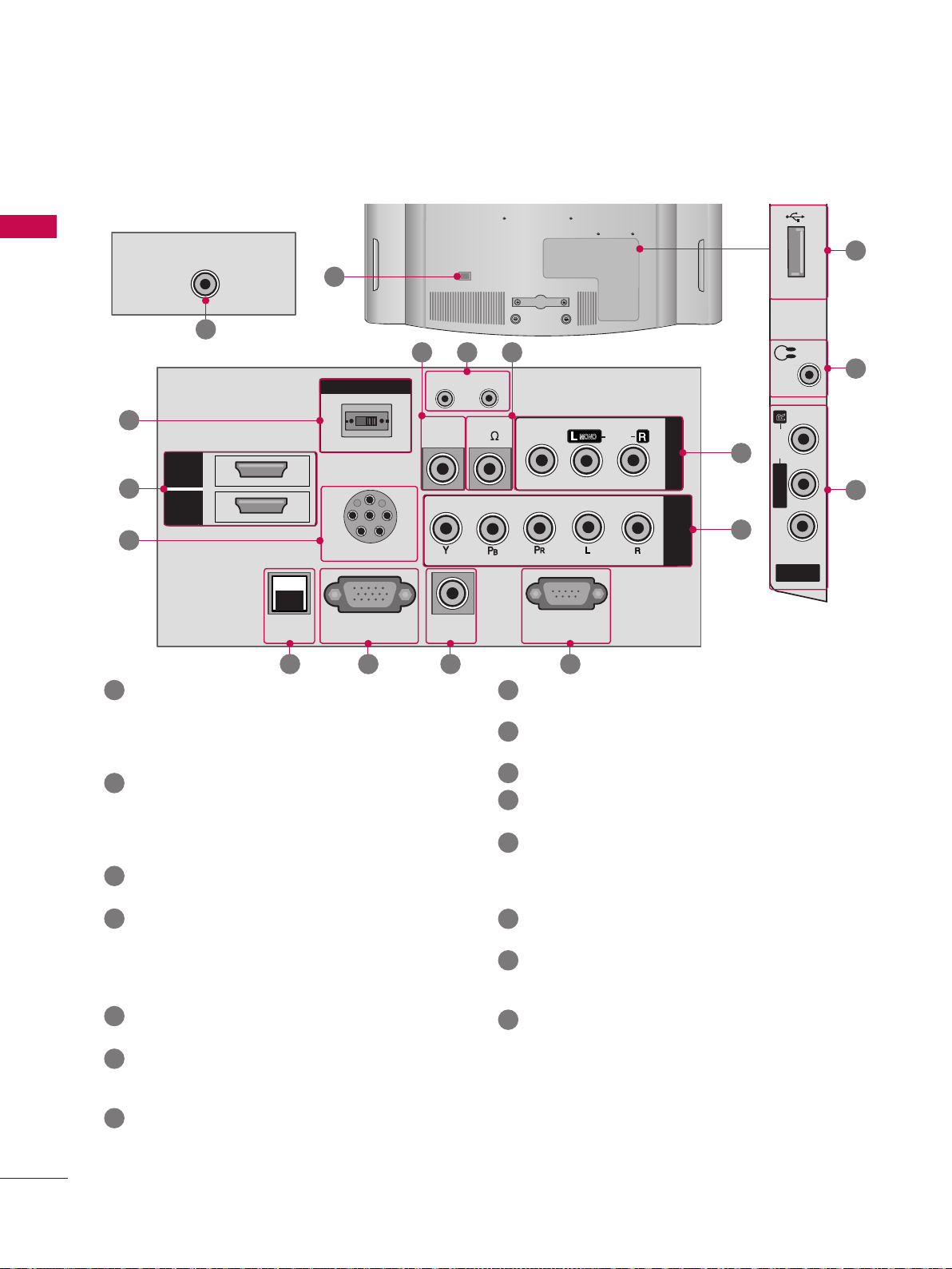
For 42LD6DDH
PREPARATION
ANTENNA IN
12
13
PILLOW
CONTROL OUT
RESET
REMOTE
AUDIO IN
(RGB/DVI)
15
HDMI
2
.2
HDMI
1
/DVI IN
15
.1
AV (Audio/Video) IN
SPEAKER SWITCH
NORMAL
PILLOW SPEAKER
RGB IN (PC)M.P.I
14 .6 .8 .5
Analog composite connection. Supports standard
definition video only (480i).
Used for PC/DTV audio input jack(Only
22LG3DDH-UA model).
.2
HDMI/DVI IN
Digital Connection.
Supports HD video and Digital audio.
Accepts DVI video using an adapter or HDMI to
DVI cable (not included).
.3
USB IN SERVICE ONLY
Used for software updates.
.4
UPDATE
Software downloads and debug mode enable/dis-
able.
RESET
Hardware reset to PTC microcontroller.
.5
RS-232C IN (SERVICE ONLY)
Used for software updates.
.6
RGB IN (PC) (Except 22LG3DDH model)
Analog PC Connection. Uses a D-sub 15-pin cable
(VGA cable).
.7
COMPONENT IN (Except 22LG3DDH model)
Analog Connection. Supports HD.
Uses a red, green, and blue cable for video & a red
and white cable for audio.
USB IN
10.9 .4
UPDATE
SPEAKER OUT
8
VIDEO
RS-232C IN
(SERVICE ONLY)
( )
MONO
AUDIO
AV IN 1
COMPONENT
IN
.1
.7
H/P
R
AUDIO
L/MONO
VIDEO
AV IN 2
.8
AUDIO IN (RGB/DVI) (Except 22LG3DDH model)
1/8” headphone jack for analog PC audio input.
.9
REMOTE CONTROL OUT
IR output for controlling an auxiliary device.
10
SPEAKER OUT 8
11
H/P
Plug the headphone into the headphone socket.
12
Power Cord Socket
For operation with AC power.
(Except 22LG3DDH model)
Ω
Caution: Never attempt to operate the TV on DC
power.
13
ANTENNA IN
Connect over-the air signals to this jack.
14
M.P. I.
Allows VOD/PPV devices or set-top boxes to con-
trol the TV.
15
PILLOW SPEAKER
Used to connect to pillow speaker.
SPEAKER SWITCH
Used to select the speaker output switch.
Note: If Pillow Speaker is selected, no Sound will be
heard from TV speakers.
(NORMAL SPEAKER or PILLOW SPEAKER)
.3
SERVICE ONLY
11
.1
10
Page 12
PROTECTION COVER
V
Image shown may differ from your TV.
After removing the stand, install the included
PROTECTION COVER over the hole for the stand.
Press the Protection cover into the TV until you hear
it click.
(FOR 26/32LG3DDH, 42LD6DDH)
PREPARATION
11
Page 13
PREPARATION
!
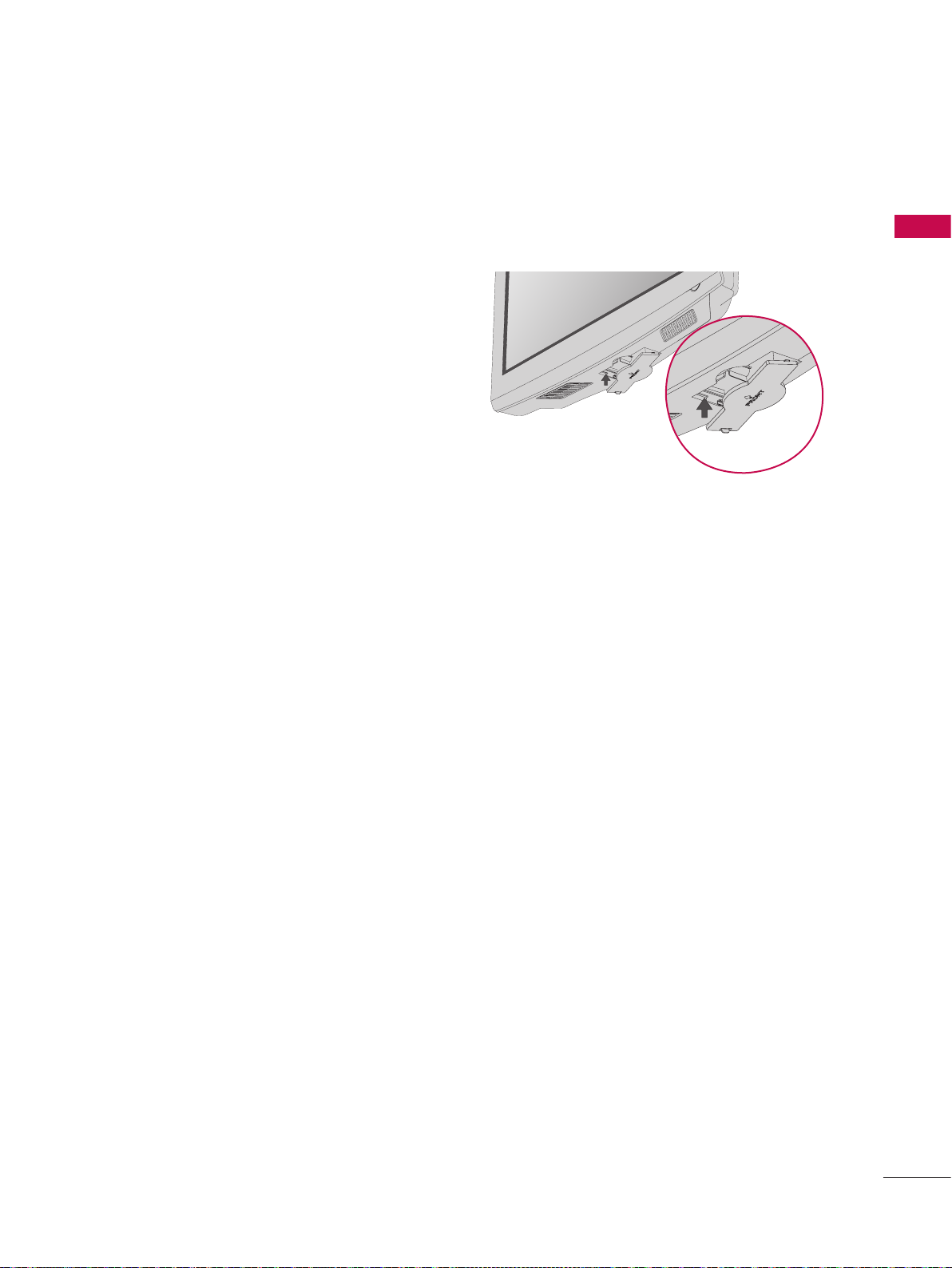
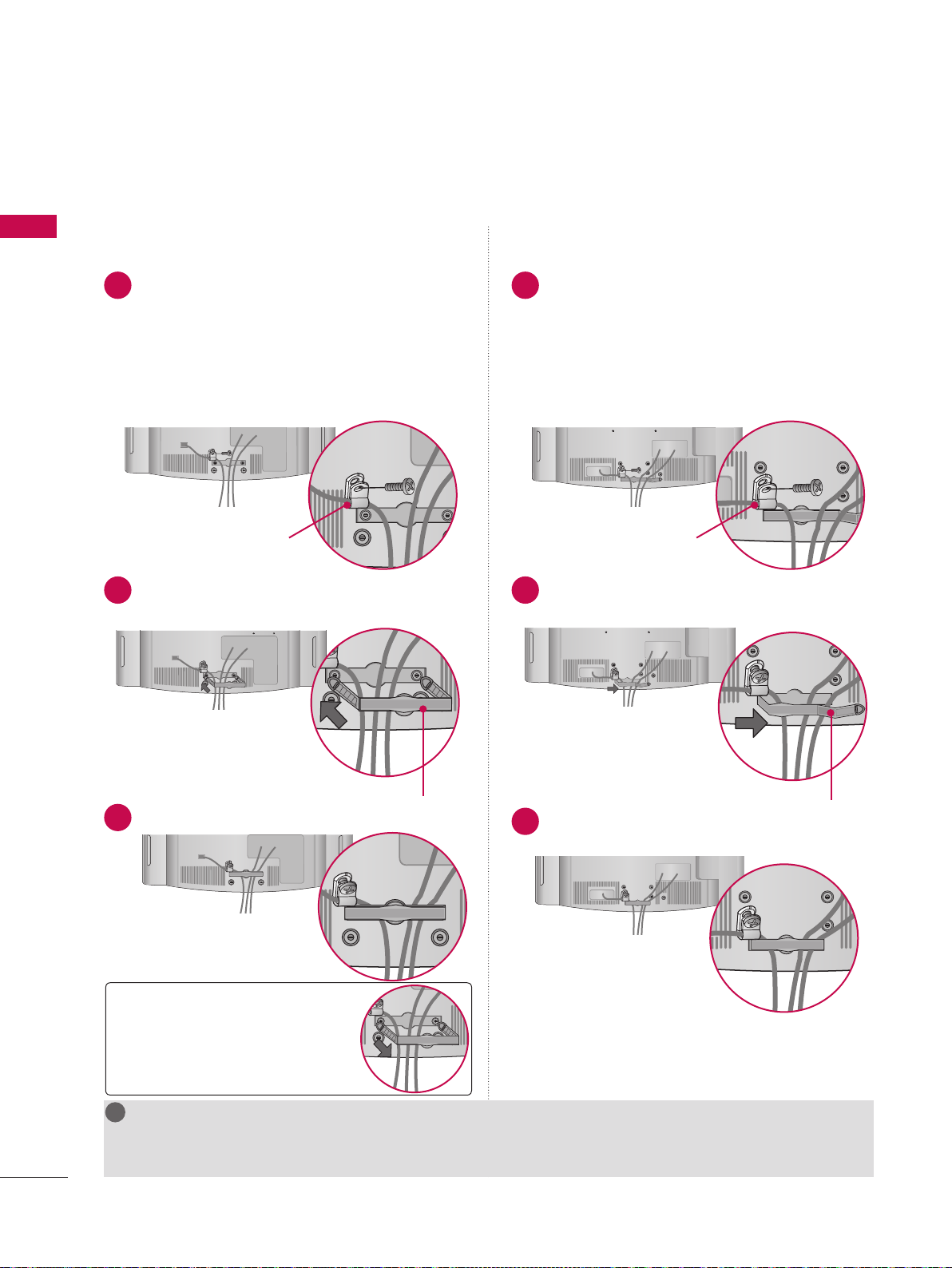
CABLE MANAGEMENT
V Image shown may differ from your TV.
PREPARATION
For 22LG3DDH
1
Connect the cables as necessary.
To connect additional equipment, see the
EXTERNAL EQUIPMENT SETUP section.
Secure the power cable with the PROTECTIVE
BRACKET/SCREW as shown.
It will help prevent the power cable from being
removed by accident.
PROTECTIVE BRACKET /SCREW
(This feature is not available for all models.)
2
Install the CABLE MANAGEMENT CLIP as
shown.
For 26/32LG3DDH, 42LD6DDH
1
Connect the cables as necessary.
To connect additional equipment, see the
EXTERNAL EQUIPMENT SETUP section.
Secure the power cable with the PROTECTIVE
BRACKET/SCREW as shown.
It will help prevent the power cable from being
removed by accident.
PROTECTIVE BRACKET /SCREW
(This feature is not available for all models.)
2
Install the CABLE MANAGEMENT CLIP as
shown.
12
CABLE MANAGEMENT CLIP
3
Fit the CABLE MANAGEMENT CLIP as shown.
3
Put the cables inside the CABLE
MANAGEMENT CLIP and snap it closed.
How to remove the
CABLE MANAGEMENT CLIP
► Hold the CABLE MANAGEMENT
CLIP with both hands and pull it
backward.
NOTE
G Do not hold the CABLE MANAGEMENT CLIP when moving the TV.
- If the TV is dropped, you may be injured or the product may be broken.
CABLE MANAGEMENT CLIP
Page 14

!
DESKTOP PEDESTAL INSTALLATION
V Image shown may differ from your TV.
V This feature is not available for all models.
For proper ventilation, allow a clearance of 4 inches on all four sides.
4 inches
4 inches 4 inches
4 inches
CAUTION
G Ensure adequate ventilation by following the clearance recommendations.
G Do not mount near or above any type of heat source.
PREPARATION
4 inches
KENSINGTON SECURITY SYSTEM
V This feature is not available for all models.
-
The TV is equipped with a Kensington Security System
connector on the back panel. Connect the Kensington Security
System cable as shown below.
-
For the detailed installation and use of the Kensington Security
System, refer to the user’s guide provided with the Kensington
Security System.
For further information, contact http://www.kensington.com,
the internet homepage of the Kensington company. Kensington
sells security systems for expensive electronic equipment such as
notebook PCs and LCD projectors.
NOTE: The Kensington Security System is an optional accessory.
13
Page 15

PREPARATION
y~XYW
ὤ㨴㥄
y~YZW
sz~YWWi
y~XYW
AA
BB
ὤ㨴㥄
y~YZW
sz~YWWi
y~XYW
AA
BB
y~YZW
sz~YWWi
y~XYW
h~T[^snZWt
AA
BB
sz~YWWi
y~XYW
!
!
!
VESA WALL MOUNTING
Install your wall mount on a solid wall perpendicular to the floor. When attaching to other building materials, please
contact your nearest installer.
PREPARATION
If installed on a ceiling or slanted wall, it may fall and result in severe personal injury.
We recommend that you use an LG brand wall mount when mounting the TV to a wall.
LG recommends that wall mounting be performed by a qualified professional installer.
Model
VESA (A * B)
AA
BB
Standard
Screw
22LG3DDH 100 * 100 M4
26LG3DDH
200
100 M4
*
32LG3DDH
42LD6DDH 200
200 M6
*
Quantity
4
4
4
Wall Mounting Bracket
(sold separately)
RW120
RW230
RW230
LSW200B, LSW200BG
AW-47LG30M
14
NOTE
G Screw length needed depends on the wall mount used. For further information, refer to the instructions
included with the mount.
G Standard dimensions for wall mount kits are shown in the table.
G When purchasing our wall mount kit, a detailed installation manual and all parts necessary for assembly are
provided.
G Do not use screws longer then the standard dimension, as they may cause damage to the inside of the TV.
G For wall mounts that do not comply with the VESA standard screw specifications, the length of the screws
may differ depending on their specifications.
G Do not use screws that do not comply with the VESA standard screw specifications.
Do not use fasten the screws too strongly, this may damage the TV or cause the TV to a fall, leading to
personal injury. LG is not liable for these kinds of accidents.
G LG is not liable for TV damage or personal injury when a non-VESA or non specified wall mount is used or
the consumer fails to follow the TV installation instructions.
CAUTION
G Do not install your wall mount kit while your TV is turned on. It may result in personal injury due to electric shock.
WARNING
G To prevent injury, this apparatus must be securely attached to the wall in accordance with the installation instructions.
Page 16
ὤ㨴㥄
ὤ㨴㥄
!
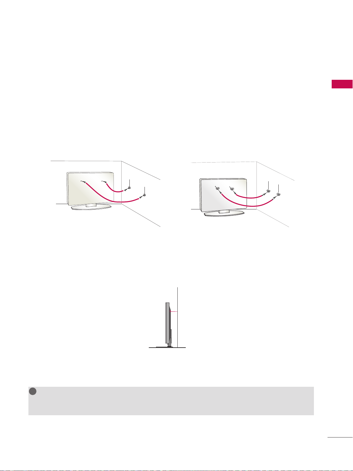
SECURING THE TV TO THE WALL TO PREVENT FALLING WHEN THE TV IS USED ON A STAND
V You should purchase necessary components to prevent TV from falling off of the stand.
V Image shown may differ from your TV.
V This feature is not available for all models.
We recommend that you set the TV close to a wall so it cannot fall over if pushed backwards.
Additionally, we recommend that the TV be attached to a wall so it cannot be pulled in a forward direction,
potentially causing injury or damaging the product.
Caution: Please make sure that children don’t climb on or hang from the TV.
V Insert the eye-bolts (or TV brackets and bolts) to tighten the product to the wall as shown in the picture.
* If your product has the bolts in the eye-bolts position before inserting the eye-bolts, loosen the bolts.
* Insert the eye-bolts or TV brackets/bolts and tighten them securely in the upper holes.
Secure the wall brackets with the bolts (sold separately) to the wall. Match the height of the bracket
that is mounted on the wall to the holes in the product.
Ensure the eye-bolts or brackets are tightened securely.
PREPARATION
V Use a sturdy rope or cord (sold separately) to tie the product. It is safer to tie the rope so it becomes
horizontal between the wall and the product (the less slack in the rope, the better).
NOTE
G Use a platform or cabinet strong enough and large enough to support the size and weight of the TV.
G To use the TV safely make sure that the height of the bracket on the wall and the one on the TV are the same.
15
Page 17
PREPARATION
Wall
Antenna
Socket
Outdoor
Antenna
(VHF, UHF)
Multi-family Dwellings/Apartments
(Connect to wall antenna socket)
RF Coaxial Wire (75
Ω)
Single-family Dwellings /Houses
(Connect to wall jack for outdoor antenna)
Be careful not to bend the copper wire
when connecting the antenna.
Copper Wire
ANTENNA IN
V To prevent damage, do not connect to the power outlet until all connections are made between the devices.
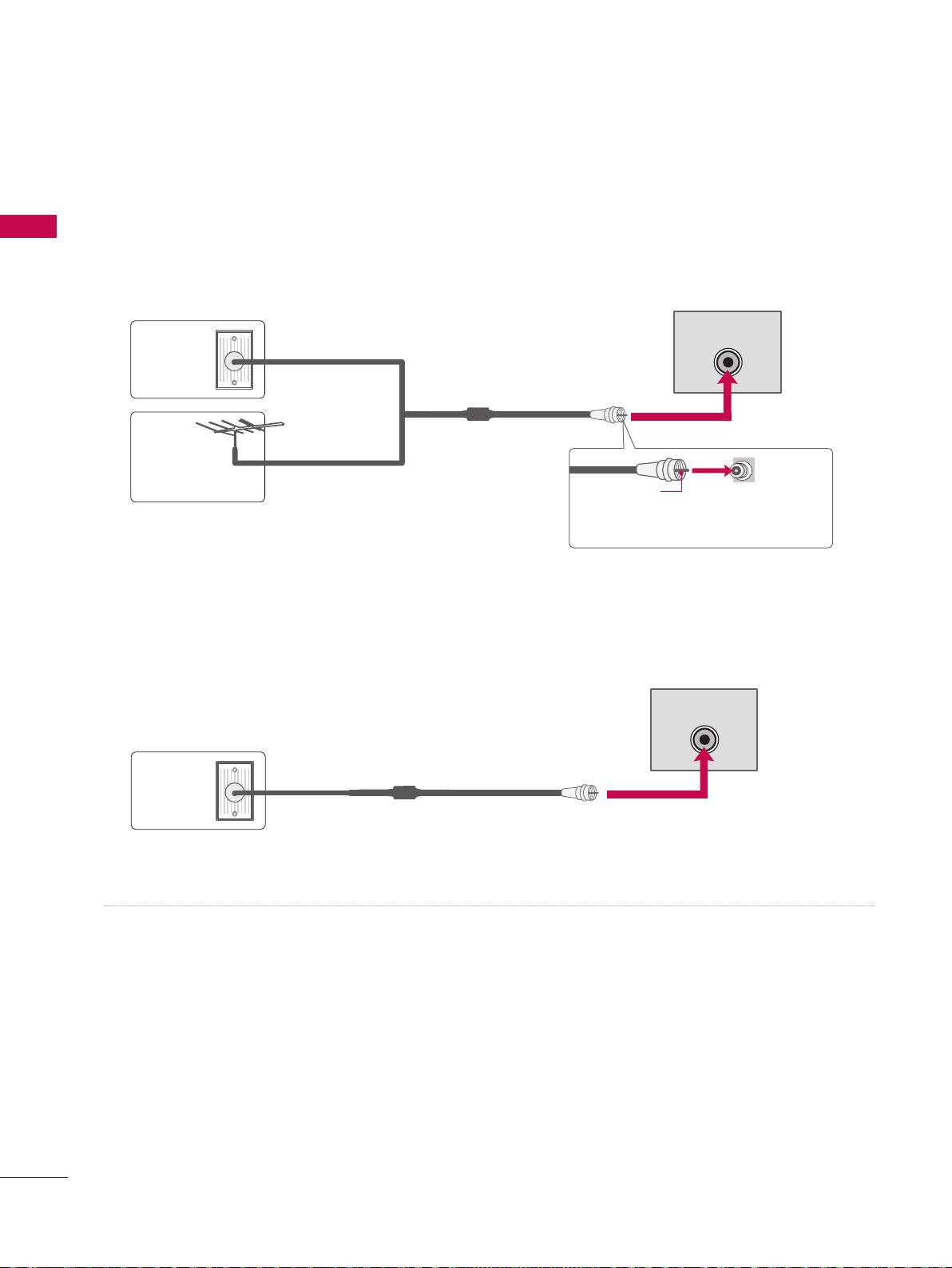
ANTENNA OR CABLE CONNECTION
PREPARATION
1. Antenna (Analog or Digital)
Wall Antenna Socket or Outdoor Antenna without a Cable Box Connection.
For optimum picture quality, adjust the direction if needed.
Wall
Multi-family Dwellings/Apartments
(Connect to wall antenna socket)
Antenna
Socket
Outdoor
RF Coaxial Wire (75
Ω)
Antenna
(VHF, UHF)
Single-family Dwellings /Houses
(Connect to wall jack for outdoor antenna)
Copper Wire
Be careful not to bend the copper wire
when connecting the antenna.
2. Cable
ANTENNA IN
ANTENNA IN
Cable
TV Wall
Jack
V To improve the picture quality in a poor signal area, please purchase a signal amplifier and install properly.
V If the antenna needs to be split for two TV’s, install a 2-Way Signal Splitter.
V If the antenna is not installed properly, contact your dealer for assistance.
RF Coaxial Wire (75 Ω)
16
Page 18

EXTERNAL EQUIPMENT SETUP
AUDIO IN
(RGB/DVI)
VIDEO
AUDIO
HDMI/DVI IN
USB IN
SERVUCE ONLY
VIDEO
MONO
( )
AUDIO
RGB IN (PC)
RESET
UPDATE
RS-232C IN
(SERVICE ONLY)
REMOTE
CONTROL OUT
SPEAKER OUT
8
PILLOW
SPEAKER
NORMAL
SPEAKER
PILLOW
SPEAKER
SPEAKER SWITCH
AUDIO IN
(RGB/DVI)
RGB IN (PC)
RESET
S-232C IN
VICE ONLY)
REMOTE
CONTROL OUT
SPEAKER OUT
8
PILLOW
SPEAKER
NORMAL
SPEAKER
PILLOW
SPEAKER
SPEAKER SWITCH
UDIO
IN
RGB/DVI
)
N
S
Y
AV IN 1
(
)
O
(PC)
RESET
E
S-232C IN
O
NLY
)
EMOTE
NTROL OU
T
PEAKER OUT
PILLOW
PEAKER
NORMA
L
PEAKER
PILLOW
PEAKE
R
PEAKER
S
WITCH
PILLOW SPEAKER
NORMAL
PILLOW
AV IN 1
VIDEO
MONO
( )
AUDIO
COMPONENT
IN
RGB IN (PC)M.P.I
RS-232C IN
(SERVICE ONLY)
AUDIO IN
(RGB/DVI)
RESET
UPDATE
REMOTE
CONTROL OUT
SPEAKER OUT
8
SPEAKER SWITCH
1
2
PILLOW
SPEAKER
HDMI/DVI IN
RS-232C IN
(SERVICE ONLY)
USB IN
SERVUCE ONLY
REMOTE
CONTROL OUT
AV IN
VIDEO
AUDIO
MONO
( )
NORMAL
SPEAKER
PILLOW
SPEAKER
SPEAKER SWITCH
RESET
UPDATE
DVI AUDIO IN
L R
S-VIDEO VIDEO
OUTPUT
SWITCH
S
-VIDEOVIDE
O
OUTPUT
SWITC
H
ANT IN
ANT OUT
2
1
Wall Jack
Antenna
1
AUDIO IN
(RGB/DVI)
VIDEO
AUDIO
HDMI/DVI IN
USB IN
SERVUCE ONLY
COMPONENT
IN
RGB IN (PC)
RS-232C IN
(SERVICE ONLY)
AUDIO I
N
(RGB/DVI
)
VIDE
O
AUDI
O
HDMI/DVI IN
SB I
N
S
ERVUCE ONL
Y
MP
O
NENT
IN
GB IN (PC
)
RS-232C IN
(S
ERVICE ONLY)
AV IN 1
VIDEO
MONO
( )
AUDIO
L
R
S-VIDEO
VIDEO
OUTPUT
SWITCH
ANT IN
ANT OUT
CO
O
IN
S3N
(
)
O
G
)
S
T
R
COOOUT
S
O
8
O
(
U
O
O
IN
O
E
O
OU
V To prevent the equipment damage, never plug in any power cords until you have finished connecting all equipment.
V This part of EXTERNAL EQUIPMENT SETUP mainly uses the picture for 32LG3DDH model.
V Image shown may differ from your TV.
HD RECEIVER SETUP
This TV can receive Digital Over-the-air or Digital Cable signals without an external digital set-top box.
However, if you do receive digital signals from a digital set-top box or other digital external device, refer to the
figure as shown below.
Component Connection (Except 22LG3DDH)
1. How to connect
Connect the video outputs (Y, PB, PR) of the digital
1
set-top box to the COMPONENT IN VIDEO jacks on
Y L RP
B
P
R
EXTERNAL EQUIPMENT SETUP
2. How to use
Supported Resolutions
the TV. Match the jack colors (Y = green, P
and P
= red).
R
Connect the audio output of the digital set-top box to
2
the COMPONENT IN AUDIO jacks on the TV.
V Turn on the digital set-top box.
(Refer to the owner’s manual for the digital set-top box.)
V Select Component input source using the INPUT button
= blue,
B
on the remote control.
Signal Component HDMI
480i Yes No
480p Yes Yes
720p Yes Yes
1080i Yes Yes
1080p No Yes
AV IN 1
COMPONENT
Y, CB/PB, CR/P
Resolution
720x480i
720x480p
1280x720p
1920x1080i
1920x1080p
HDMI/DVI IN
HDMI/DVI I
IN
R
Frequency(kHz)
1
AUDIO
AUDI
VIDEO
Horizontal
15.73
15.73
31.47
31.50
44.96
45.00
33.72
33.75
67.500
67.432
27.000
26.97
33.75
33.71
UPDATE
PDAT
USB IN
USB IN
SERVUCE ONLY
ERVUCE ONL
( )
MONO
VIDEO
VIDEO
AUDIO
Vertical
Frequency(Hz)
24.000
23.976
30.000
2
RGB IN
59.94
60.00
59.94
60.00
59.94
60.00
59.94
60.00
60.00
59.94
29.97
R
R
(SER
ERVICE
A
For 42LD6DDH
17
Page 19

ὤ㨴㥄
AUDIO IN
(RGB/DVI)
VIDEO
AUDIO
HDMI/DVI IN
USB IN
SERVUCE ONLY
AV IN 1
VIDEO
MONO
( )
AUDIO
COMPONENT
IN
RGB IN (PC)
RESET
UPDATE
RS-232C IN
(SERVICE ONLY)
REMOTE
CONTROL OUT
SPEAKER OUT
8
PILLOW
SPEAKER
NORMAL
SPEAKER
PILLOW
SPEAKER
SPEAKER SWITCH
AUDIO IN
(RGB/DVI)
HDMI/DVI IN
USB IN
SERVUCE ONLY
AV IN 1
VIDEO
MONO
( )
AUDIO
RGB IN (PC)
RESET
UPDATE
RS-232C IN
(SERVICE ONLY)
REMOTE
CONTROL OUT
SPEAKER OUT
8
PILLOW
SPEAKER
NORMAL
SPEAKER
PILLOW
SPEAKER
SPEAKER SWITCH
AUDIO IN
RGB/DVI
)
HDMI/DVI I
N
USB IN
S
ERVUCE ONL
Y
VIDEO
(
)
AUDI
O
RGB IN (PC
)
RESET
PDAT
E
RS-232C IN
ERVICE ONLY
)
EMOTE
NTROL OU
T
S
PEAKER OUT
PILLOW
S
PEAKER
NORMA
L
S
PEAKER
PILLOW
S
PEAKE
R
PEAKER
S
WITCH
COMPONENT
IN
VIDEO
AUDIO
Y L RP
B
P
R
1
2
PILLOW SPEAKER
NORMAL
PILLOW
AV IN 1
VIDEO
MONO
( )
AUDIO
COMPONENT
IN
RGB IN (PC)M.P.I
RS-232C IN
(SERVICE ONLY)
AUDIO IN
(RGB/DVI)
RESET
UPDATE
REMOTE
CONTROL OUT
SPEAKER OUT
8
SPEAKER SWITCH
HDMI
/DVI IN
HDMI
1
2
AUDIO
UPDATE
S
Y
O
AUDIO
O
(
)
O
O
O
IN
PILLOW SPEAKER
NORMAL
PILLOW
RGB IN (PC)M.P.I
SPEAKER SWITCH
ILLOW SPEAKE
R
N
O
RMA
L
PILL
OW
RGB IN (PC
)
.P.
I
S
PEAKER SWITCH
HDMI
/DVI IN
HDMI
1
2
1
PILLOW
SPEAKER
HDMI/DVI IN
RS-232C IN
(SERVICE ONLY)
USB IN
SERVUCE ONLY
REMOTE
CONTROL OUT
AV IN
VIDEO
AUDIO
MONO
( )
NORMAL
SPEAKER
PILLOW
SPEAKER
SPEAKER SWITCH
RESET
UPDATE
DVI AUDIO IN
L R
S-VIDEO VIDEO
OUTPUT
SWITCH
S
-VIDEOVIDE
O
OUTPUT
SWITC
H
ANT IN
ANT OUT
2
1
Wall Jack
Antenna
1
AUDIO IN
(RGB/DVI)
VIDEO
AUDIO
HDMI/DVI IN
USB IN
SERVUCE ONLY
COMPONENT
IN
RGB IN (PC)
RS-232C IN
(SERVICE ONLY)
AUDI
O
N
(R
G
)
VIDE
O
AUDI
O
HDMI/DVI IN
SB I
N
S
ERVUCE ONL
Y
MP
O
NENT
IN
GB IN
(
)
RS-2
3
(S
ERVI
C
O
AV IN 1
VIDEO
MONO
( )
AUDIO
L
R
S-VIDEO
VIDEO
OUTPUT
SWITCH
ANT IN
ANT OUT
CO
O
IN
S3N
(
)
O
G
)
S
T
R
COOOUT
SO8
AV IN 2
L/MONO
R
AUDIO
VIDEO
H/P
L R
VIDEO
1
Camcorder
Video Game Set
/
3
(SCO
)
N
SUCO
Y
O
E
COOO
S
T
E
O
(
U
O
O
IN
O
E
O
OU
AUDIO IN
RESET
REMOTE
CONTROL OUT
SPEAKER OUT
8
PILLOW
SPEAKER
NORMAL
SPEAKER
PILLOW
SPEAKER
SPEAKER SWITCH
AUDIO IN
(RGB/DVI)
RESET
REMOTE
CONTROL OUT
SPEAKER OUT
8
PILLOW
SPEAKER
NORMAL
SPEAKER
PILLOW
SPEAKER
SPEAKER SWITCH
AUDIO IN
RGB/DVI
)
(PC)
RESET
ERVICE ONLY
)
EMOTE
NTROL OU
T
S
PEAKER OUT
PILLOW
S
PEAKER
NORMA
L
S
PEAKER
PILLOW
S
PEAKE
R
PEAKER
S
WITCH
AV IN 1
VIDEO
MONO
( )
AUDIO
COMPONENT
IN
RS-232C IN
(SERVICE ONLY)
AUDIO IN
(RGB/DVI)
UPDATE
REMOTE
SPEAKER OUT
8
NORMAL
PILLOW
SPEAKER SWITCH
R
N
O
RMA
L
PILL
OW
)
I
S
PEAKER SWITCH
HDMI/DVI IN
RS-232C IN
(SERVICE ONLY)
USB IN
SERVUCE ONLY
REMOTE
CONTROL OUT
AV IN
VIDEO
AUDIO
MONO
( )
RESET
UPDATE
DVI AUDIO IN
L R
S-VIDEO VIDEO
OUTPUT
SWITCH
S
-VIDEOVIDE
O
OUTPUT
SWITC
H
ANT IN
ANT OUT
ANTENNA IN
2
1
Wall Jack
Antenna
1
AUDIO IN
(RGB/DVI)
VIDEO
AUDIO
HDMI/DVI IN
USB IN
SERVUCE ONLY
COMPONENT
IN
RGB IN (PC)
RS-232C IN
(SERVICE ONLY)
AUDIO I
N
(RGB/DVI
)
VIDE
O
AUDI
O
HDMI/DVI IN
SB I
N
S
ERVUCE ONL
Y
MP
O
NENT
IN
GB IN (PC
)
RS-232C IN
(S
ERVICE ONLY)
AV IN 1
VIDEO
MONO
( )
AUDIO
L
R
S-VIDEO
VIDEO
OUTPUT
SWITCH
ANT IN
ANT OUT
COMPONENT
IN
RS-232C IN
(SERVICE ONLY)
AUDIO IN
(RGB/DVI)
RESET
UPDATE
REMOTE
CONTROL OUT
SPEAKER OUT
8
CO
MP
O
NENT
IN
RS-232C I
N
(
SERVICE ONLY
)
AUDIO IN
(RGB/DVI
)
ESE
T
R
EMOTE
CO
NTROL
OUT
S
PEAKER OUT
8
AV IN 1
VIDEO
MONO
( )
AUDIO
1
L
R
S-VIDEO
VIDEO
OUTPUT
SWITCH
ANT IN
ANT OUT
AV IN 2
L/MONO
R
AUDIO
VIDEO
H/P
L R
VIDEO
1
Camcorder
Video Game Set
HDMI/DVI IN
RS-232C IN
(SERVICE ONLY)
USB IN
SERVUCE ONLY
REMOTE
CONTROL OUT
RESET
UPDATE
DMI/DVI IN
-232C IN
(S
ERVICE ONLY
)
B I
N
S
ERVUCE ONL
Y
REMOT
E
CO
NTROL OUT
ESE
T
PDAT
E
AV IN
VIDEO
AUDIO
MONO
( )
DVI AUDIO IN
L R
VIDEO
1
Camcorder
VIDEO
AV IN 1
COMPONENT
IN
VIDE
O
AV IN 1
(
U
O
MP
O
NENT
IN
O
E
O
OU
EXTERNAL EQUIPMENT SETUP
18
EXTERNAL EQUIPMENT SETUP
Vertical
59.94
60.00
59.94
60.00
59.94
60.00
60.00
59.939
24.000
23.976
30.000
29.97
For 42LD6DDH
HDMI Connection
1. How to connect
Connectthedigitalset-topboxtoHDMI/DVI IN, 1or
1
2* jackontheTV.
Noseparateaudioconnectionisnecessary.
2
HDMIsupportsbothaudioandvideo.
2. How to use
VTurnonthedigitalset-topbox.
(Refertotheowner’smanualforthedigitalset-topbox.)
VSelectHDMI/HDMI 1orHDMI 2* inputsourcewith
usingtheINPUTbuttonontheremotecontrol.
*HDMI2:For42LD6DDH
HDMI-DTV
Resolution
720x480p
Horizontal
Frequency(kHz)
1280x720p
1920x1080i
1920x1080p
31.469
31.500
44.96
45.00
33.72
33.75
67.50
67.432
27.000
26.97
33.75
33.71
Frequency(Hz)
26/32LG3DDH
42LD6DDH
HDMI
HDMI
/DVI IN
AV IN 1
AV IN 1
NENT
MP
COMPONENT
IN
C
2
1
HDMI-DTV OUTPUT
HDMI/DVI IN
1
VIDEO
VIDE
HDMI-DTV OUTPUT
.P.
1
USB IN
SERVUCE ONLY
ERVUCE ONL
( )
AUDIO
AUDI
MONO
PILLOW SPEAKER
ILLOW SPEAKE
RGB IN (PC)M.P.I
RGB IN (PC
B IN
VIDEO
VIDE
Page 20

SPEAKER OUT
8
SPEAKER SWITCH
SPEAKER OUT
8
SPEAKER SWITCH
S
PEAKER OUT
8
L
R
PEAKER
S
WITCH
AV IN 1
AUDIO
COMPONENT
IN
PILLOW SPEAKER
NORMAL
PILLOW
RGB IN (PC)M.P.I
ILLOW SPEAKE
R
N
O
RMA
L
PILL
OW
RGB IN (PC
)
PEAKER SWITCH
RESET
UPDATE
DVI AUDIO IN
RS-232C IN
(SERVICE ONLY)
USB IN
SERVUCE ONLY
REMOTE
CONTROL OUT
NORMAL
SPEAKER
RESET
UPDATE
W
R
-232C IN
(S
ERVICE ONLY)
B I
N
S
ERVUCE ONL
Y
REMOT
E
CO
NTROL OUT
ORMAL
S
PEAKER
R
S
WIT
CH
ESE
T
HDMI/DVI IN
AV IN
VIDEO
AUDIO
MONO
( )
DVI AUDIO IN
L R
DVI-DTV OUTPUT
L
R
1
2
PILLOW SPEAKER
NORMAL
PILLOW
AV IN 1
VIDEO
MONO
( )
AUDIO
COMPONENT
IN
RGB IN (PC)M.P.I
RS-232C IN
(SERVICE ONLY)
RESET
UPDATE
REMOTE
CONTROL OUT
SPEAKER OUT
8
SPEAKER SWITCH
PILLOW SPEAKE
R
N
O
RMA
L
PILL
OW
AV IN 1
VIDE
O
(
)
AUDI
O
CO
MP
O
NENT
IN
GB IN (PC
)
.P.
-232C IN
(S
ERVICE ONLY)
ESET
REMOT
E
CO
NTROL OUT
S
PEAKER
OUT
8
S
PEAKER SWITCH
AUDIO IN
(RGB/DVI)
HDMI
/DVI IN
HDMI
1
2
1
2
L R
S-VIDEO VIDEO
OUTPUT
SWITCH
S
-VIDEOVIDE
O
OUTPUT
SWITC
H
ANT IN
ANT OUT
ANTENNA IN
2
1
Wall Jack
Antenna
1
AUDIO IN
(RGB/DVI)
VIDEO
AUDIO
HDMI/DVI IN
USB IN
SERVUCE ONLY
COMPONENT
IN
RGB IN (PC)
RS-232C IN
(SERVICE ONLY)
AUDIO I
N
(RGB/DVI
)
VIDE
O
AUDI
O
HDMI/DVI IN
SB I
N
S
ERVUCE ONL
Y
MP
O
NENT
IN
GB IN (PC
)
RS-232C IN
(S
ERVICE ONLY)
AV IN 1
VIDEO
MONO
( )
AUDIO
L
R
S-VIDEO
VIDEO
OUTPUT
SWITCH
ANT IN
ANT OUT
COMPONENT
IN
RS-232C IN
(SERVICE ONLY)
AUDIO IN
(RGB/DVI)
RESET
UPDATE
REMOTE
CONTROL OUT
SPEAKER OUT
8
CO
MP
O
NENT
IN
RS-232C I
N
(
SERVICE ONLY
)
AUDIO IN
(RGB/DVI
)
ESE
T
R
EMOTE
CO
NTROL
OUT
S
PEAKER OUT
8
AV IN 1
VIDEO
MONO
( )
AUDIO
1
L
R
S-VIDEO
VIDEO
OUTPUT
SWITCH
ANT IN
ANT OUT
AV IN 2
L/MONO
R
AUDIO
VIDEO
H/P
L R
VIDEO
1
Camcorder
Video Game Set
AV IN 2
L/MONO
R
AUDIO
VIDEO
H/P
USB IN
SERVICE ONLY
L R
VIDEO
1
Camcorder
Video Game Set
HDMI/DVI IN
RS-232C IN
(SERVICE ONLY)
USB IN
SERVUCE ONLY
REMOTE
CONTROL OUT
RESET
UPDATE
DMI/DVI IN
-232C IN
(S
ERVICE ONLY
)
B I
N
S
ERVUCE ONL
Y
REMOT
E
CO
NTROL OUT
ESE
T
PDAT
E
AV IN
VIDEO
AUDIO
MONO
( )
DVI AUDIO IN
L R
VIDEO
1
Camcorder
Video Game Set
VIDEO
AUDIO
AV IN 1
VIDEO
MONO
( )
AUDIO
COMPONENT
IN
REMOTE
CONTROL OUT
VIDE
O
AUDIO
AV IN 1
VIDEO
(
)
AUDI
O
MP
O
NENT
IN
REMOT
E
CO
NTROL OUT
AUDIO IN
(RGB/DVI)
RGB IN (PC)
RGB OUTPUT
AUDIO
21
!
AUDIO IN
(RGB/DVI)
VIDEO
AUDIO
HDMI/DVI IN
USB IN
SERVUCE ONLY
AV IN 1
VIDEO
MONO
( )
AUDIO
COMPONENT
IN
RGB IN (PC)
RESET
UPDATE
RS-232C IN
(SERVICE ONLY)
REMOTE
CONTROL OUT
SPEAKER OUT
8
PILLOW
SPEAKER
NORMAL
SPEAKER
PILLOW
SPEAKER
SPEAKER SWITCH
AUDIO IN
(RGB/DVI)
HDMI/DVI IN
USB IN
SERVUCE ONLY
AV IN 1
VIDEO
MONO
( )
AUDIO
RGB IN (PC)
RESET
UPDATE
RS-232C IN
(SERVICE ONLY)
REMOTE
CONTROL OUT
SPEAKER OUT
8
PILLOW
SPEAKER
NORMAL
SPEAKER
PILLOW
SPEAKER
SPEAKER SWITCH
AUDIO IN
(
RGB/DVI
)
HDMI/DVI I
N
USB IN
S
ERVUCE ONL
Y
AV IN 1
VIDEO
MONO
(
)
AUDI
O
RGB IN (PC
)
RESET
PDAT
E
RS-232C IN
(S
ERVICE ONLY
)
EMOTE
CO
NTROL OU
T
S
PEAKER OUT
8
PILLOW
S
PEAKER
NORMA
L
S
PEAKER
PILLOW
S
PEAKE
R
PEAKER
S
WITCH
COMPONENT
IN
VIDEO
AUDIO
Y L RPBP
R
1
2
PILLOW SPEAKER
NORMAL
PILLOW
AV IN 1
VIDEO
MONO
( )
AUDIO
COMPONENT
IN
RGB IN (PC)M.P.I
RS-232C IN
(SERVICE ONLY)
AUDIO IN
(RGB/DVI)
RESET
UPDATE
REMOTE
CONTROL OUT
SPEAKER OUT
8
SPEAKER SWITCH
HDMI
/DVI IN
HDMI
1
2
VIDEO
AUDIO
USB IN
SERVUCE ONLY
AV IN 1
VIDEO
MONO
( )
AUDIO
COMPONENT
IN
UPDATE
B IN
S
ERVUCE ONL
Y
VIDE
O
AUDIO
AV IN 1
VIDE
O
(
)
AUDI
O
C
O
MP
O
NENT
IN
HDMI/DVI IN
HDMI-DTV OUTPUT
1
PILLOW SPEAKER
NORMAL
PILLOW
RGB IN (PC)M.P.I
SPEAKER SWITCH
ILLOW SPEAKE
R
N
O
RMA
L
PILL
OW
RGB IN (PC
)
.
.
S
PEAKER SWITCH
HDMI
/DVI IN
HDMI
1
2
HDMI-DTV OUTPUT
1
VIDEO
AUDIO
USB IN
SERVUCE ONLY
AV IN 1
VIDEO
MONO
( )
AUDIO
COMPONENT
IN
RGB IN (PC)
UPDATE
RS-232C IN
(SERVICE ONLY)
USB IN
S
ERVUCE ONL
Y
AV IN
1
VIDE
O
VIDE
O
AUDI
O
(
)
AUDI
O
COMPONENT
IN
RGB IN (PC)
-232C IN
(S
ERVICE ONLY
)
AUDIO IN
(RGB/DVI)
HDMI/DVI IN
L R
DVI-DTV OUTPUT
L
R
1
2
PILLOW
SPEAKER
HDMI/DVI IN
RS-232C IN
(SERVICE ONLY)
USB IN
SERVUCE ONLY
REMOTE
CONTROL OUT
AV IN
VIDEO
AUDIO
MONO
( )
NORMAL
SPEAKER
PILLOW
SPEAKER
SPEAKER SWITCH
RESET
UPDATE
DVI AUDIO IN
PILLOW
SPEAKER
RS-232C IN
(SERVICE ONLY)
USB IN
SERVUCE ONLY
REMOTE
CONTROL OUT
NORMAL
SPEAKER
PILLOW
SPEAKER
SPEAKER SWITCH
RESET
UPDATE
ILLO
W
S
PEAKE
R
-232C IN
(S
ERVICE ONLY)
B I
N
S
ERVUCE ONL
Y
REMOT
E
CO
NTROL OUT
ORMAL
S
PEAKER
PILL
OW
S
PEAKE
R
S
PEAKER SWIT
CH
ESE
T
HDMI/DVI IN
AV IN
VIDEO
AUDIO
MONO
( )
DVI AUDIO IN
L R
DVI-DTV OUTPUT
L
R
1
2
PILLOW SPEAKER
NORMAL
PILLOW
VIDEO
RGB IN (PC)M.P.I
RESET
UPDATE
REMOTE
CONTROL OUT
SPEAKER OUT
8
SPEAKER SWITCH
PILLOW SPEAKE
R
N
O
RMA
L
PILL
OW
VIDE
O
(
U
O
CO
O
IN
GB IN (PC
)
.P.
I
3
(SCO
ESET
REMOT
E
CO
NTROL OUT
S
PEAKER
OUT
8
S
PEAKER SWITCH
AUDIO IN
(RGB/DVI)
HDMI
/DVI IN
HDMI
1
2
1
2
L R
S-VIDEO VIDEO
OUTPUT
SWITCH
S
-VIDEOVIDE
O
OUTPUT
SWITC
H
ANT IN
ANT OUT
ANTENNA IN
2
1
Wall Jack
Antenna
1
AUDIO IN
(RGB/DVI)
VIDEO
AUDIO
HDMI/DVI IN
USB IN
SERVUCE ONLY
COMPONENT
IN
RGB IN (PC)
RS-232C IN
(SERVICE ONLY)
AUDIO I
N
(RGB/DVI
)
VIDE
O
AUDI
O
HDMI/DVI IN
SB I
N
S
ERVUCE ONL
Y
MP
O
NENT
IN
GB IN (PC
)
RS-232C IN
(S
ERVICE ONLY)
AV IN 1
VIDEO
MONO
( )
AUDIO
L
R
S-VIDEO
VIDEO
OUTPUT
SWITCH
ANT IN
ANT OUT
COMPONENT
IN
RS-232C IN
(SERVICE ONLY)
AUDIO IN
(RGB/DVI)
RESET
UPDATE
REMOTE
CONTROL OUT
SPEAKER OUT
8
CO
MP
O
NENT
IN
RS-232C I
N
(
SERVICE ONLY
)
AUDIO IN
(RGB/DVI
)
ESE
T
R
EMOTE
CO
NTROL
OUT
S
PEAKER OUT
8
AV IN 1
VIDEO
MONO
( )
AUDIO
1
L
R
S-VIDEO
VIDEO
OUTPUT
SWITCH
ANT IN
ANT OUT
AV IN 2
L/MONO
R
AUDIO
VIDEO
H/P
L R
VIDEO
1
Camcorder
Video Game Set
HDMI/DVI IN
RS-232C IN
(SERVICE ONLY)
USB IN
SERVUCE ONLY
REMOTE
CONTROL OUT
RESET
UPDATE
DMI/DVI IN
-232C IN
(S
ERVICE ONLY
)
B I
N
S
ERVUCE ONL
Y
REMOT
E
CO
NTROL OUT
ESE
T
PDAT
E
AV IN
VIDEO
AUDIO
MONO
( )
DVI AUDIO IN
L R
VIDEO
1
Camcorder
Video Game Set
VIDEO
AV IN 1
AUDIO
COMPONENT
IN
VIDE
O
AV IN 1
(
AUDI
O
MP
O
NENT
IN
O
E
COOOU
PILLOW SPEAKER
NORMAL
PILLOW
AV IN 1
VIDEO
MONO
( )
AUDIO
COMPONENT
IN
RGB IN (PC)M.P.I
RS-232C IN
(SERVICE ONLY)
RESET
UPDATE
REMOTE
CONTROL OUT
SPEAKER OUT
8
SPEAKER SWITCH
PILLOW SPEAKE
R
N
O
RMA
L
PILL
OW
AV IN 1
VIDE
O
(
)
AUDI
O
CO
MP
O
NENT
IN
GB IN (PC
)
.P.
-232C IN
(S
ERVICE ONLY)
ESET
REMOT
E
CO
NTROL OUT
S
PEAKER
OUT
8
S
PEAKER SWITCH
AUDIO IN
(RGB/DVI)
HDMI
/DVI IN
HDMI
1
2
L R
DVI-DTV OUTPUT
L
R
1
2
ANTENNA IN
O IN
G
B/DVI
)
(PC)
3
2C IN
CE O
NLY)
COMPONENT
IN
RS-232C IN
(SERVICE ONLY)
AUDIO IN
(RGB/DVI)
RESET
UPDATE
REMOTE
CONTROL OUT
SPEAKER OUT
8
CO
MP
O
NENT
IN
RS-232C I
N
(
SERVICE ONLY
)
AUDIO IN
(RGB/DVI
)
ESE
T
R
EMOTE
CO
NTROL
OUT
S
PEAKER OUT
8
AV IN 1
VIDEO
MONO
( )
AUDIO
1
L
R
S-VIDEO
VIDEO
OUTPUT
SWITCH
ANT IN
ANT OUT
AV IN 2
L/MONO
R
AUDIO
VIDEO
H/P
USB IN
SERVICE ONLY
L R
VIDEO
1
Camcorder
Video Game Set
HDMI/DVI IN
RS-232C IN
(SERVICE ONLY)
USB IN
SERVUCE ONLY
REMOTE
CONTROL OUT
RESET
UPDATE
DMI/DVI IN
-232C IN
(S
ERVICE ONLY
)
B I
N
S
ERVUCE ONL
Y
REMOT
E
CO
NTROL OUT
ESE
T
PDAT
E
AV IN
VIDEO
AUDIO
MONO
( )
DVI AUDIO IN
L R
VIDEO
1
Camcorder
Video Game Set
VIDEO
AUDIO
AV IN 1
VIDEO
MONO
( )
AUDIO
COMPONENT
IN
REMOTE
CONTROL OUT
VIDE
O
AUDIO
AV IN 1
VIDEO
(
)
AUDI
O
MP
O
NENT
IN
REMOT
E
CO
NTROL OUT
AUDIO IN
(RGB/DVI)
RGB IN (PC)
RGB OUTPUT
AUDIO
21
DVI to HDMI Connection
1. How to connect
2. How to use
ConnecttheDVIoutputofthedigitalset-topboxto
1
Connecttheaudiooutputofthedigitalset-topboxto
2
VTurnonthedigitalset-topbox.
(Refertotheowner’smanualforthedigitalset-topbox.)
VSelecttheHDMIorHDMI 1inputsourceontheTV
usingtheINPUTbuttonontheremotecontrol.
NOTE
G ADVItoHDMIcableoradapterisrequiredfor
thisconnection.DVIdoesn'tsupportaudio,soa
separateaudioconnectionisnecessary.
theHDMI/DVI INor1 jackontheTV.
theAUDIO IN(RGB/DVI)orAV IN AUDIO jackon
theTV.
22LG3DDH
26/32LG3DDH
42LD6DDH
19
EXTERNAL EQUIPMENT SETUP
Page 21

EXTERNAL EQUIPMENT SETUP
AUDIO IN
(RGB/DVI)
VIDEO
AUDIO
HDMI/DVI IN
USB IN
SERVUCE ONLY
VIDEO
MONO
( )
AUDIO
RGB IN (PC)
RESET
UPDATE
RS-232C IN
(SERVICE ONLY)
REMOTE
CONTROL OUT
SPEAKER OUT
8
PILLOW
SPEAKER
NORMAL
SPEAKER
PILLOW
SPEAKER
SPEAKER SWITCH
AUDIO IN
(RGB/DVI)
RGB IN (PC)
RESET
S-232C IN
VICE ONLY)
REMOTE
CONTROL OUT
SPEAKER OUT
8
PILLOW
SPEAKER
NORMAL
SPEAKER
PILLOW
SPEAKER
SPEAKER SWITCH
UDIO
IN
RGB/DVI
)
N
S
Y
(
)
O
(PC)
RESET
E
S-232C IN
O
NLY
)
EMOTE
NTROL OU
T
PEAKER OUT
PILLOW
PEAKER
NORMA
L
PEAKER
PILLOW
PEAKE
R
PEAKER
S
WITCH
PILLOW SPEAKER
NORMAL
PILLOW
AV IN 1
VIDEO
MONO
( )
AUDIO
COMPONENT
IN
RGB IN (PC)M.P.I
RS-232C IN
(SERVICE ONLY)
AUDIO IN
(RGB/DVI)
RESET
UPDATE
REMOTE
CONTROL OUT
SPEAKER OUT
8
SPEAKER SWITCH
1
2
PILLOW
SPEAKER
HDMI/DVI IN
RS-232C IN
(SERVICE ONLY)
USB IN
SERVUCE ONLY
REMOTE
CONTROL OUT
AV IN
VIDEO
AUDIO
MONO
( )
NORMAL
SPEAKER
PILLOW
SPEAKER
SPEAKER SWITCH
RESET
UPDATE
DVI AUDIO IN
L R
S-VIDEO VIDEO
OUTPUT
SWITCH
S
-VIDEOVIDE
O
OUTPUT
SWITC
H
ANT IN
ANT OUT
2
1
Wall Jack
Antenna
1
AUDIO IN
(RGB/DVI)
VIDEO
AUDIO
HDMI/DVI IN
USB IN
SERVUCE ONLY
COMPONENT
IN
RGB IN (PC)
RS-232C IN
(SERVICE ONLY)
AUDIO I
N
(RGB/DVI
)
VIDE
O
AUDI
O
HDMI/DVI IN
SB I
N
S
ERVUCE ONL
Y
MP
O
NENT
IN
GB IN (PC
)
RS-232C IN
(S
ERVICE ONLY)
AV IN 1
VIDEO
MONO
( )
AUDIO
L
R
S-VIDEO
VIDEO
OUTPUT
SWITCH
ANT IN
ANT OUT
CO
O
IN
S3N
(
)
O
G
)
S
T
R
COOOUT
S
O
8
O
(
U
O
O
IN
O
E
O
OU
DVD SETUP
Component Connection (Except 22LG3DDH)
EXTERNAL EQUIPMENT SETUP
1. How to connect
Connectthevideooutputs(Y,PB,PR)oftheDVDto
1
Y L RP
B
P
R
theCOMPONENT IN VIDEOjacksontheTV.Match
thejackcolors(Y=green,PB=blue,andPR=red).
ConnecttheaudiooutputsoftheDVDtothe
2
COMPONENT IN AUDIOjacksontheTV.
2. How to use
VTurnontheDVDplayer,insertaDVD.
VSelecttheComponent inputsourceontheTVusingthe
VRefertotheDVDplayer'smanualforoperating
Component Input ports
INPUTbuttonontheremotecontrol.
instructions.
AV IN 1
COMPONENT
IN
HDMI/DVI IN
HDMI/DVI I
1
VIDEO
AUDIO
AUDI
USB IN
USB IN
SERVUCE ONLY
ERVUCE ONL
( )
MONO
VIDEO
VIDEO
To get better picture quality, connect a DVD player to the component input ports as shown below.
UPDATE
PDAT
2
AUDIO
R
R
(SER
ERVICE
RGB IN
A
ComponentportsontheTV
Videooutputports
onDVDplayer
Y P
Y PB PR
Y B-Y R-Y
Y C
Y PB PR
B
B CR
P
R
20
Page 22

ὤ㨴㥄
AUDIO IN
(RGB/DVI)
VIDEO
AUDIO
HDMI/DVI IN
USB IN
SERVUCE ONLY
AV IN 1
VIDEO
MONO
( )
AUDIO
COMPONENT
IN
RGB IN (PC)
RESET
UPDATE
RS-232C IN
(SERVICE ONLY)
REMOTE
CONTROL OUT
SPEAKER OUT
8
PILLOW
SPEAKER
NORMAL
SPEAKER
PILLOW
SPEAKER
SPEAKER SWITCH
AUDIO IN
(RGB/DVI)
HDMI/DVI IN
USB IN
SERVUCE ONLY
AV IN 1
VIDEO
MONO
( )
AUDIO
RGB IN (PC)
RESET
UPDATE
RS-232C IN
(SERVICE ONLY)
REMOTE
CONTROL OUT
SPEAKER OUT
8
PILLOW
SPEAKER
NORMAL
SPEAKER
PILLOW
SPEAKER
SPEAKER SWITCH
AUDIO IN
RGB/DVI
)
HDMI/DVI I
N
USB IN
S
ERVUCE ONL
Y
VIDEO
(
)
AUDI
O
RGB IN (PC
)
RESET
PDAT
E
RS-232C IN
ERVICE ONLY
)
EMOTE
NTROL OU
T
S
PEAKER OUT
PILLOW
S
PEAKER
NORMA
L
S
PEAKER
PILLOW
S
PEAKE
R
PEAKER
S
WITCH
COMPONENT
IN
VIDEO
AUDIO
Y L RP
B
P
R
1
2
PILLOW SPEAKER
NORMAL
PILLOW
AV IN 1
VIDEO
MONO
( )
AUDIO
COMPONENT
IN
RGB IN (PC)M.P.I
RS-232C IN
(SERVICE ONLY)
AUDIO IN
(RGB/DVI)
RESET
UPDATE
REMOTE
CONTROL OUT
SPEAKER OUT
8
SPEAKER SWITCH
HDMI
/DVI IN
HDMI
1
2
AUDIO
UPDATE
S
Y
O
AUDIO
O
(
)
O
O
O
IN
PILLOW SPEAKER
NORMAL
PILLOW
RGB IN (PC)M.P.I
SPEAKER SWITCH
ILLOW SPEAKE
R
N
O
RMA
L
PILL
OW
RGB IN (PC
)
.P.
I
S
PEAKER SWITCH
HDMI
/DVI IN
HDMI
1
2
1
PILLOW
SPEAKER
HDMI/DVI IN
RS-232C IN
(SERVICE ONLY)
USB IN
SERVUCE ONLY
REMOTE
CONTROL OUT
AV IN
VIDEO
AUDIO
MONO
( )
NORMAL
SPEAKER
PILLOW
SPEAKER
SPEAKER SWITCH
RESET
UPDATE
DVI AUDIO IN
L R
S-VIDEO VIDEO
OUTPUT
SWITCH
S
-VIDEOVIDE
O
OUTPUT
SWITC
H
ANT IN
ANT OUT
2
1
Wall Jack
Antenna
1
AUDIO IN
(RGB/DVI)
VIDEO
AUDIO
HDMI/DVI IN
USB IN
SERVUCE ONLY
COMPONENT
IN
RGB IN (PC)
RS-232C IN
(SERVICE ONLY)
AUDI
O
N
(R
G
)
VIDE
O
AUDI
O
HDMI/DVI IN
SB I
N
S
ERVUCE ONL
Y
MP
O
NENT
IN
GB IN
(
)
RS-2
3
(S
ERVI
C
O
AV IN 1
VIDEO
MONO
( )
AUDIO
L
R
S-VIDEO
VIDEO
OUTPUT
SWITCH
ANT IN
ANT OUT
CO
O
IN
S3N
(
)
O
G
)
S
T
R
COOOUT
SO8
AV IN 2
L/MONO
R
AUDIO
VIDEO
H/P
L R
VIDEO
1
Camcorder
Video Game Set
/
3
(SCO
)
N
SUCO
Y
O
E
COOO
S
T
E
O
(
U
O
O
IN
O
E
O
OU
AUDIO IN
RESET
REMOTE
CONTROL OUT
SPEAKER OUT
8
PILLOW
SPEAKER
NORMAL
SPEAKER
PILLOW
SPEAKER
SPEAKER SWITCH
AUDIO IN
(RGB/DVI)
RESET
REMOTE
CONTROL OUT
SPEAKER OUT
8
PILLOW
SPEAKER
NORMAL
SPEAKER
PILLOW
SPEAKER
SPEAKER SWITCH
AUDIO IN
RGB/DVI
)
(PC)
RESET
ERVICE ONLY
)
EMOTE
NTROL OU
T
S
PEAKER OUT
PILLOW
S
PEAKER
NORMA
L
S
PEAKER
PILLOW
S
PEAKE
R
PEAKER
S
WITCH
AV IN 1
VIDEO
MONO
( )
AUDIO
COMPONENT
IN
RS-232C IN
(SERVICE ONLY)
AUDIO IN
(RGB/DVI)
UPDATE
REMOTE
SPEAKER OUT
8
NORMAL
PILLOW
SPEAKER SWITCH
R
N
O
RMA
L
PILL
OW
)
I
S
PEAKER SWITCH
HDMI/DVI IN
RS-232C IN
(SERVICE ONLY)
USB IN
SERVUCE ONLY
REMOTE
CONTROL OUT
AV IN
VIDEO
AUDIO
MONO
( )
RESET
UPDATE
DVI AUDIO IN
L R
S-VIDEO VIDEO
OUTPUT
SWITCH
S
-VIDEOVIDE
O
OUTPUT
SWITC
H
ANT IN
ANT OUT
ANTENNA IN
2
1
Wall Jack
Antenna
1
AUDIO IN
(RGB/DVI)
VIDEO
AUDIO
HDMI/DVI IN
USB IN
SERVUCE ONLY
COMPONENT
IN
RGB IN (PC)
RS-232C IN
(SERVICE ONLY)
AUDIO I
N
(RGB/DVI
)
VIDE
O
AUDI
O
HDMI/DVI IN
SB I
N
S
ERVUCE ONL
Y
MP
O
NENT
IN
GB IN (PC
)
RS-232C IN
(S
ERVICE ONLY)
AV IN 1
VIDEO
MONO
( )
AUDIO
L
R
S-VIDEO
VIDEO
OUTPUT
SWITCH
ANT IN
ANT OUT
COMPONENT
IN
RS-232C IN
(SERVICE ONLY)
AUDIO IN
(RGB/DVI)
RESET
UPDATE
REMOTE
CONTROL OUT
SPEAKER OUT
8
CO
MP
O
NENT
IN
RS-232C I
N
(
SERVICE ONLY
)
AUDIO IN
(RGB/DVI
)
ESE
T
R
EMOTE
CO
NTROL
OUT
S
PEAKER OUT
8
AV IN 1
VIDEO
MONO
( )
AUDIO
1
L
R
S-VIDEO
VIDEO
OUTPUT
SWITCH
ANT IN
ANT OUT
AV IN 2
L/MONO
R
AUDIO
VIDEO
H/P
L R
VIDEO
1
Camcorder
Video Game Set
HDMI/DVI IN
RS-232C IN
(SERVICE ONLY)
USB IN
SERVUCE ONLY
REMOTE
CONTROL OUT
RESET
UPDATE
DMI/DVI IN
-232C IN
(S
ERVICE ONLY
)
B I
N
S
ERVUCE ONL
Y
REMOT
E
CO
NTROL OUT
ESE
T
PDAT
E
AV IN
VIDEO
AUDIO
MONO
( )
DVI AUDIO IN
L R
VIDEO
1
Camcorder
VIDEO
AV IN 1
COMPONENT
IN
VIDE
O
AV IN 1
(
U
O
MP
O
NENT
IN
O
E
O
OU
HDMI Connection
1. How to connect
ConnecttheHDMIoutputoftheDVDtothe
1
HDMI/DVI IN ,1 or 2* jackontheTV.
Noseparateaudioconnectionisnecessary.
2
HDMIsupportsbothaudioandvideo.
2. How to use
VSelecttheHDMI/HDMI 1orHDMI 2* inputsourceon
theTVusingtheINPUTbuttonontheremotecontrol.
VRefertotheDVDplayer'smanualforoperating
instructions.
*HDMI2:For42LD6DDH
26/32LG3DDH
AV IN 1
AV IN 1
NENT
MP
COMPONENT
C
42LD6DDH
HDMI
2
HDMI
1
/DVI IN
HDMI/DVI IN
1
VIDEO
IN
VIDE
HDMI-DTV OUTPUT
.P.
1
AUDIO
AUDI
PILLOW SPEAKER
ILLOW SPEAKE
RGB IN (PC)M.P.I
RGB IN (PC
USB IN
B IN
SERVUCE ONLY
ERVUCE ONL
( )
MONO
VIDEO
VIDE
EXTERNAL EQUIPMENT SETUP
HDMI-DTV OUTPUT
21
Page 23

EXTERNAL EQUIPMENT SETUP
L R
S-VIDEO VIDEO
OUTPUT
SWITCH
S
-VIDEOVIDE
O
OUTPUT
SWITC
H
ANT IN
ANT OUT
ANTENNA IN
2
1
Wall Jack
Antenna
VIDEO
AUDIO
AV IN 1
VIDEO
MONO
( )
AUDIO
COMPONENT
IN
REMOTE
CONTROL OUT
VIDE
O
AUDIO
AV IN 1
VIDEO
(
)
AUDI
O
MP
O
NENT
IN
REMOT
E
NTROL
OU
AUDIO IN
(RGB/DVI)
RGB IN (PC)
21
VCR SETUP
V To avoid picture noise (interference), leave an adequate distance between the VCR and TV.
V If the 4:3 picture format is used; the fixed images on the sides of the screen may remain visible on the screen.
This phenomenon is common to all TVs and is not covered by warranty.
Antenna Connection
EXTERNAL EQUIPMENT SETUP
1. How to connect
Connect the RF antenna out socket of the VCR to the
1
ANTENNA IN socket on the TV.
Connect the antenna cable to the RF antenna in
2
socket of the VCR.
2. How to use
V Set VCR output switch to 3 or 4 and then tune TV to the
same channel number.
V Insert a video tape into the VCR and press PLAY on the
VCR. (Refer to the VCR owner’s manual.)
22
Page 24

!
Composite (RCA) Connection
L R
S-VIDEO VIDEO
OUTPUT
SWITCH
S
-VIDEOVIDE
O
OUTPUT
SWITC
H
ANT IN
ANT OUT
ANTENNA IN
2
1
Wall Jack
Antenna
HDMI/DVI IN
USB IN
SERVUCE ONLY
RS-232C IN
(SERVICE ONLY)
N
)
O
O
HDMI/DVI IN
SB I
N
S
ERVUCE ONL
Y
O
)
RS-232C IN
(S
ERVICE ONLY)
COMPONENT
IN
RS-232C IN
(SERVICE ONLY)
AUDIO IN
(RGB/DVI)
RESET
UPDATE
REMOTE
CONTROL OUT
SPEAKER OUT
8
CO
MP
O
NENT
IN
RS-232C I
N
(
SERVICE ONLY
)
AUDIO IN
(RGB/DVI
)
ESE
T
R
EMOTE
CO
NTROL
OUT
S
PEAKER OUT
8
AV IN 1
VIDEO
MONO
( )
AUDIO
1
L
R
S-VIDEO
VIDEO
OUTPUT
SWITCH
ANT IN
ANT OUT
VIDEO
AUDIO
AV IN 1
VIDEO
MONO
( )
AUDIO
COMPONENT
IN
REMOTE
CONTROL OUT
VIDE
O
AUDIO
AV IN 1
VIDEO
(
)
AUDI
O
MP
O
NENT
IN
REM
O
E
NTR
O
OU
AUDIO IN
(RGB/DVI)
RGB IN (PC)
RGB OUTPUT
AUDIO
21
RESET
UPDATE
CO
O
IN
N
(
)
)
ESE
T
R
CO
OUT
S
8
VIDEO
AUDIO
AV IN 1
VIDEO
MONO
( )
AUDIO
COMPONENT
IN
REMOTE
CONTROL OUT
VIDE
O
AUDIO
AV IN 1
VIDEO
(
)
AUDI
O
MP
O
NENT
IN
REMOT
E
NTROL OUT
AUDIO IN
(RGB/DVI)
RGB IN (PC)
RGB OUTPUT
AUDIO
21
1. How to connect
Connect the AUDIO/VIDEO jacks between TV and
1
VCR. Match the jack colors (Video = yellow, Audio Left
= white, and Audio Right = red)
2. How to use
V Insert a video tape into the VCR and press PLAY on the
VCR. (Refer to the VCR owner’s manual.)
V Select the AV or AV 1 input source on the TV using the
INPUT button on the remote control.
V If connected to AV IN 2, select AV2 input source on the
NOTE
G If you have a mono VCR, connect the audio
cable from the VCR to the AUDIO L(MONO)
TV(Except 22LG3DDH).
jack of the TV.
26/32LG3DDH
AV IN 1
NENT
MP
COMPONENT
IN
IN
ANT OUT
ANT IN
REMOTE
EMOTE
NTROL
SPEAKER OUT
PEAKER OUT
8
42LD6DDH
CONTROL OUT
VIDEO
VIDE
R
AUDIO
VIDEO
( )
MONO
L
( )
MONO
1
VIDEO
AUDIO
AUDI
VIDEO
AUDIO
RGB IN (PC)
GB IN (PC
S-VIDEO
OUTPUT
SWITCH
AV IN 1
COMPONENT
IN
MP
NENT
AUDIO IN
AUDIO I
(RGB/DVI)
(RGB/DVI
EXTERNAL EQUIPMENT SETUP
AUDIO IN
AUDIO IN
(RGB/DVI)
(RGB/DVI
ANT OUT
ANT IN
RS-232C IN
RS-232C I
(SERVICE ONLY)
SERVICE ONLY
R
1
VIDEO
S-VIDEO
OUTPUT
SWITCH
L
23
Page 25

EXTERNAL EQUIPMENT SETUP
COMPONENT
IN
RS-232C IN
(SERVICE ONLY)
CO
MP
O
NENT
IN
RS-232C I
N
(
SERVICE ONLY
)
AV IN 1
VIDEO
MONO
( )
AUDIO
1
L
R
S-VIDEO
VIDEO
OUTPUT
SWITCH
L/MONO
R
AUDIO
H/P
USB IN
SERVICE ONLY
L R
VIDEO
1
Camcorder
Video Game Set
T
E
Camcorder
VIDEO
AUDIO
AV IN 1
VIDEO
MONO
( )
AUDIO
COMPONENT
IN
REMOTE
CONTROL OUT
VIDE
O
AUDIO
AV IN 1
VIDEO
(
)
AUDI
O
MP
O
NENT
IN
REMOT
E
CO
NTROL OUT
AUDIO IN
(RGB/DVI)
RGB IN (PC)
RGB OUTPUT
AUDIO
21
L R
S-VIDEO VIDEO
OUTPUT
SWITCH
S
-VIDEOVIDE
O
OUTPUT
SWITC
H
ANT IN
ANT OUT
ANTENNA IN
2
1
Wall Jack
Antenna
1
AUDIO IN
(RGB/DVI)
VIDEO
AUDIO
HDMI/DVI IN
USB IN
SERVUCE ONLY
COMPONENT
IN
RGB IN (PC)
RS-232C IN
(SERVICE ONLY)
AUDIO I
N
(RGB/DVI
)
VIDE
O
AUDI
O
HDMI/DVI IN
SB I
N
S
ERVUCE ONL
Y
MP
O
NENT
IN
GB IN (PC
)
RS-232C IN
(S
ERVICE ONLY)
AV IN 1
VIDEO
MONO
( )
AUDIO
L
R
S-VIDEO
VIDEO
OUTPUT
SWITCH
ANT IN
ANT OUT
COMPONENT
IN
RS-232C IN
(SERVICE ONLY)
AUDIO IN
(RGB/DVI)
RESET
UPDATE
REMOTE
CONTROL OUT
SPEAKER OUT
8
CO
MP
O
NENT
IN
RS-232C I
N
(
SERVICE ONLY
)
AUDIO IN
(RGB/DVI
)
ESE
T
R
EMOTE
CO
NTROL
OUT
S
PEAKER OUT
8
AV IN 1
VIDEO
MONO
( )
AUDIO
1
L
R
S-VIDEO
VIDEO
OUTPUT
SWITCH
ANT IN
ANT OUT
Camcorder
L/MONO
R
AUDIO
H/P
USB IN
SERVICE ONLY
L R
VIDEO
1
Camcorder
Video Game Set
HDMI/DVI IN
RS-232C IN
(SERVICE ONLY)
RESET
UPDATE
DMI/DVI IN
-232C IN
(S
ERVICE ONLY
)
ESE
T
PDAT
E
AV IN
VIDEO
AUDIO
MONO
( )
DVI AUDIO IN
L R
VIDEO
1
Camcorder
Video Game Set
VIDEO
AUDIO
AV IN 1
VIDEO
MONO
( )
AUDIO
COMPONENT
IN
REMOTE
CONTROL OUT
VIDE
O
AUDIO
AV IN 1
VIDEO
(
)
AUDI
O
MP
O
NENT
IN
REMOT
E
CO
NTROL OUT
AUDIO IN
(RGB/DVI)
RGB IN (PC)
RGB OUTPUT
AUDIO
21
AV IN 2
L/MONO
R
AUDIO
VIDEO
H/P
USB IN
SERVICE ONLY
L R
VIDEO
1
Camcorder
Video Game Set
REMOTE
CONTROL OUT
REMOT
E
CO
NTROL OUT
AUDIO IN
(RGB/DVI)
RGB IN (PC)
AUDIO
21
OTHER A/V SOURCE SETUP
EXTERNAL EQUIPMENT SETUP
1. How to connect
Connect the AUDIO/VIDEO jacks between TV and
1
external equipment. Match the jack colors. (Video =
yellow, Audio Left = white, and Audio Right = red)
2. How to use
V Select the AV2 input source on the TV using the INPUT
button on the remote control. (Except 22LG3DDH)
V If connected to AV IN or AV IN 1 input, select the AV or
V Operate the corresponding external equipment.
AV1 input source on the TV.
22LG3DDH
Video Game Set
L R
VIDEO
AV IN
1
AUDIO
MONO
( )
VIDEO
DVI AUDIO IN
RESET
ESE
PDAT
UPDATE
26/32LG3DDH
H/P
R
AUDIO
VIDEO
Video Game Set
L R
1
L/MONO
VIDEO
42LD6DDH
24
Page 26

PILLOW SPEAKER SETUP
V Connect a pillow speaker to the LCD TV/Monitor.
1. How to connect
Connect the PILLOW SPEAKER output jack on the
1
EXTERNAL EQUIPMENT SETUP
back of the TV.
Connect an accessory pillow speaker or wired remote
2
control unit to this 6-pin jack.
Select PILLOW SPEAKER on the rear panel of the TV.
3
Use a pillow speaker that is a UL recognized pendant control
bearing the warning:
“Risk of fire if used in oxygen enriched atmosphere.
Keep pendant control away from oxygen equipment.”
Controlling the TV with Serial Data
The TV is capable of being controlled by a single-wire, serial data
signal. This is a LG patented technology and is being implemented
by certain brands of “smart” pillow speakers.
Pillow Speaker Interface
This connector furnishes three control lines and an audio output.
A patient-pendant remote control, or entertainment audio and
nurse call system may be connected here. All lines are isolated
from the AC power line and earth ground. (Optoisolators isolate
the control lines, and a transformer isolates the audio. There are
no relays or inductive components in the control lines.)
PILLOW
SPEAKER
NORMAL
SPEAKER
PILLOW
SPEAKER
SPEAKER SWITCH
pin No. Purpose
1 External TV On/Off switch.
2 (Not used.)
3 External Channel Up switch or Data in.
Common connection for control, data, and audio
4
output. Impedance to earth ground is a 10-meg
resistor in parallel with a 1100 pf capacitor.
Isolated audio output. Nominal 14-ohm source
impedance with short circuit protection. Intended
5
for a pillow speaker with a low-impe ance padtype volume control.
6 External Channel Down switch.
Controlling the TV with Mechanical Switches
Pin 4(common) is momentarily connected to
pin 1, 3, or 6 via push-action switches to
control On/Off and Channel Up/Down.
These pins are at +13volts DC(when measured
from pin4) with the switches open.
Current draw is 8 mA when a switch is closed.
(This opebration is identical to previous LG
models using the 5-Wire Interface except that
only +7 volts DC was supplied and current
draw was only 2.5 mA.)
25
Page 27

EXTERNAL EQUIPMENT SETUP
E
!
PC SETUP
This TV provides Plug and Play capability, meaning that the PC adjusts automatically to the TV's settings.
VGA (D-Sub 15-pin) Connection (Except 22LG3DDH)
EXTERNAL EQUIPMENT SETUP
26
1. How to connect
ConnecttheVGAoutputofthePCtotheRGB IN
1
(PC)
jackontheTV.
ConnectthePCaudiooutputtotheAUDIO IN
2
(RGB/DVI)
jackontheTV.
2. How to use
VTurnonthePCandtheTV.
VSelectthe RGB-PCinputsourceontheTVusingthe
INPUTbuttonontheremotecontrol.
Supported Display Specifications
(RGB-PC, HDMI-PC)
Resolution
640x350
RGB-PC
640x480
HDMI-PC
720x400
RGB-PC
640x480
RGB-PC
Horizontal
Frequency(kHz)
31.469 70.08
31.469 59.94
31.469 70.08
31.469 59.94
800x600 37.879 60.31
1024x768 48.363 60.00
1280x768 47.776 59.87
1360x768 47.720 59.799
1360x768
HDMI-PC
1366x768
RGB-PC
1366x768
HDMI-PC
47.712 60.015
47.13 59.65
47.13 59.65
1028x1024 63.981 60.02
1600x1200 75.00 60.00
1920x1080
RGB-PC
1920x1080
RGB-PC
66.587 59.934
67.50 60.00
Vertical
Frequency(Hz)
For 42LD6DDHFor 22/26/32LG3DDH
)
)
VIDEO
VIDEO
AUDIO
AUDIO
RGB IN (PC)
RGB OUTPUT
AUDIO IN
(RGB/DVI)
21
AUDIO
REMOTE
REMOT
CONTROL OUT
NTROL OUT
NOTE
GTogetthethebestpicturequality,adjustthePC
graphicscardto1360x768(22/26/32LG3DDH)
or1920x1080(42LD6DDH).
GDependingonthegraphicscard,DOSmodemay
notworkifaHDMItoDVICableisinuse.
GIn PCmode, there maybe noiseassociatedwith
theresolution,verticalpattern,contrastor
brightness.Ifnoiseispresent,changethePC
outputtoanotherresolution,changetherefresh
ratetoanotherrateoradjustthebrightnessand
contrastonthePICTUREmenuuntilthepictureis
clear.
GAvoid keeping a fixed image on the screenfor a
longperiodoftime.Thefixedimagecouldbecome
permanentlyimprintedonthescreen.
GThesynchronizationinputformforHorizontaland
Verticalfrequenciesisseparate.
GDependingonthegraphicscard,someresolution
settingsmaynotallowtheimagetobepositioned
onthescreenproperly.
Page 28

SPEAKER OUT
8
SPEAKER SWITCH
SPEAKER OUT
8
SPEAKER SWITCH
S
PEAKER OUT
8
L
R
PEAKER
S
WITCH
AV IN 1
AUDIO
COMPONENT
IN
PILLOW SPEAKER
NORMAL
PILLOW
RGB IN (PC)M.P.I
ILLOW SPEAKE
R
N
O
RMA
L
PILL
OW
RGB IN (PC
)
PEAKER SWITCH
RESET
UPDATE
DVI AUDIO IN
RS-232C IN
(SERVICE ONLY)
USB IN
SERVUCE ONLY
REMOTE
CONTROL OUT
NORMAL
SPEAKER
RESET
UPDATE
W
R
-232C IN
(S
ERVICE ONLY)
B I
N
S
ERVUCE ONL
Y
REMOT
E
CO
NTROL OUT
ORMAL
S
PEAKER
R
S
WIT
CH
ESE
T
HDMI/DVI IN
AV IN
VIDEO
AUDIO
MONO
( )
DVI AUDIO IN
L R
DVI-DTV OUTPUT
L
R
1
2
PILLOW SPEAKER
NORMAL
PILLOW
AV IN 1
VIDEO
MONO
( )
AUDIO
COMPONENT
IN
RGB IN (PC)M.P.I
RS-232C IN
(SERVICE ONLY)
RESET
UPDATE
REMOTE
CONTROL OUT
SPEAKER OUT
8
SPEAKER SWITCH
PILLOW SPEAKE
R
N
O
RMA
L
PILL
OW
AV IN 1
VIDE
O
(
)
AUDI
O
CO
MP
O
NENT
IN
GB IN (PC
)
.P.
-232C IN
(S
ERVICE ONLY)
ESET
REMOT
E
CO
NTROL OUT
S
PEAKER
OUT
8
S
PEAKER SWITCH
AUDIO IN
(RGB/DVI)
HDMI
/DVI IN
HDMI
1
2
1
2
L R
S-VIDEO VIDEO
OUTPUT
SWITCH
S
-VIDEOVIDE
O
OUTPUT
SWITC
H
ANT IN
ANT OUT
ANTENNA IN
2
1
Wall Jack
Antenna
1
AUDIO IN
(RGB/DVI)
VIDEO
AUDIO
HDMI/DVI IN
USB IN
SERVUCE ONLY
COMPONENT
IN
RGB IN (PC)
RS-232C IN
(SERVICE ONLY)
AUDIO I
N
(RGB/DVI
)
VIDE
O
AUDI
O
HDMI/DVI IN
SB I
N
S
ERVUCE ONL
Y
MP
O
NENT
IN
GB IN (PC
)
RS-232C IN
(S
ERVICE ONLY)
AV IN 1
VIDEO
MONO
( )
AUDIO
L
R
S-VIDEO
VIDEO
OUTPUT
SWITCH
ANT IN
ANT OUT
COMPONENT
IN
RS-232C IN
(SERVICE ONLY)
AUDIO IN
(RGB/DVI)
RESET
UPDATE
REMOTE
CONTROL OUT
SPEAKER OUT
8
CO
MP
O
NENT
IN
RS-232C I
N
(
SERVICE ONLY
)
AUDIO IN
(RGB/DVI
)
ESE
T
R
EMOTE
CO
NTROL
OUT
S
PEAKER OUT
8
AV IN 1
VIDEO
MONO
( )
AUDIO
1
L
R
S-VIDEO
VIDEO
OUTPUT
SWITCH
ANT IN
ANT OUT
AV IN 2
L/MONO
R
AUDIO
VIDEO
H/P
L R
VIDEO
1
Camcorder
Video Game Set
AV IN 2
L/MONO
R
AUDIO
VIDEO
H/P
USB IN
SERVICE ONLY
L R
VIDEO
1
Camcorder
Video Game Set
HDMI/DVI IN
RS-232C IN
(SERVICE ONLY)
USB IN
SERVUCE ONLY
REMOTE
CONTROL OUT
RESET
UPDATE
DMI/DVI IN
-232C IN
(S
ERVICE ONLY
)
B I
N
S
ERVUCE ONL
Y
REMOT
E
CO
NTROL OUT
ESE
T
PDAT
E
AV IN
VIDEO
AUDIO
MONO
( )
DVI AUDIO IN
L R
VIDEO
1
Camcorder
Video Game Set
VIDEO
AUDIO
AV IN 1
VIDEO
MONO
( )
AUDIO
COMPONENT
IN
REMOTE
CONTROL OUT
VIDE
O
AUDIO
AV IN 1
VIDEO
(
)
AUDI
O
MP
O
NENT
IN
REMOT
E
CO
NTROL OUT
AUDIO IN
(RGB/DVI)
RGB IN (PC)
RGB OUTPUT
AUDIO
21
AUDIO IN
(RGB/DVI)
VIDEO
AUDIO
HDMI/DVI IN
USB IN
SERVUCE ONLY
AV IN 1
VIDEO
MONO
( )
AUDIO
COMPONENT
IN
RGB IN (PC)
RESET
UPDATE
RS-232C IN
(SERVICE ONLY)
REMOTE
CONTROL OUT
SPEAKER OUT
8
PILLOW
SPEAKER
NORMAL
SPEAKER
PILLOW
SPEAKER
SPEAKER SWITCH
AUDIO IN
(RGB/DVI)
HDMI/DVI IN
USB IN
SERVUCE ONLY
AV IN 1
VIDEO
MONO
( )
AUDIO
RGB IN (PC)
RESET
UPDATE
RS-232C IN
(SERVICE ONLY)
REMOTE
CONTROL OUT
SPEAKER OUT
8
PILLOW
SPEAKER
NORMAL
SPEAKER
PILLOW
SPEAKER
SPEAKER SWITCH
AUDIO IN
(
RGB/DVI
)
HDMI/DVI I
N
USB IN
S
ERVUCE ONL
Y
AV IN 1
VIDEO
MONO
(
)
AUDI
O
RGB IN (PC
)
RESET
PDAT
E
RS-232C IN
(S
ERVICE ONLY
)
EMOTE
CO
NTROL OU
T
S
PEAKER OUT
8
PILLOW
S
PEAKER
NORMA
L
S
PEAKER
PILLOW
S
PEAKE
R
PEAKER
S
WITCH
COMPONENT
IN
VIDEO
AUDIO
Y L RPBP
R
1
2
PILLOW SPEAKER
NORMAL
PILLOW
AV IN 1
VIDEO
MONO
( )
AUDIO
COMPONENT
IN
RGB IN (PC)M.P.I
RS-232C IN
(SERVICE ONLY)
AUDIO IN
(RGB/DVI)
RESET
UPDATE
REMOTE
CONTROL OUT
SPEAKER OUT
8
SPEAKER SWITCH
HDMI
/DVI IN
HDMI
1
2
VIDEO
AUDIO
USB IN
SERVUCE ONLY
AV IN 1
VIDEO
MONO
( )
AUDIO
COMPONENT
IN
UPDATE
B IN
S
ERVUCE ONL
Y
VIDE
O
AUDIO
AV IN 1
VIDE
O
(
)
AUDI
O
C
O
MP
O
NENT
IN
HDMI/DVI IN
HDMI-DTV OUTPUT
1
PILLOW SPEAKER
NORMAL
PILLOW
RGB IN (PC)M.P.I
SPEAKER SWITCH
ILLOW SPEAKE
R
N
O
RMA
L
PILL
OW
RGB IN (PC
)
.
.
S
PEAKER SWITCH
HDMI
/DVI IN
HDMI
1
2
HDMI-DTV OUTPUT
1
VIDEO
AUDIO
USB IN
SERVUCE ONLY
AV IN 1
VIDEO
MONO
( )
AUDIO
COMPONENT
IN
RGB IN (PC)
UPDATE
RS-232C IN
(SERVICE ONLY)
USB IN
S
ERVUCE ONL
Y
AV IN
1
VIDE
O
VIDE
O
AUDI
O
(
)
AUDI
O
COMPONENT
IN
RGB IN (PC)
-232C IN
(S
ERVICE ONLY
)
AUDIO IN
(RGB/DVI)
HDMI/DVI IN
L R
DVI-DTV OUTPUT
L
R
1
2
PILLOW
SPEAKER
HDMI/DVI IN
RS-232C IN
(SERVICE ONLY)
USB IN
SERVUCE ONLY
REMOTE
CONTROL OUT
AV IN
VIDEO
AUDIO
MONO
( )
NORMAL
SPEAKER
PILLOW
SPEAKER
SPEAKER SWITCH
RESET
UPDATE
DVI AUDIO IN
PILLOW
SPEAKER
RS-232C IN
(SERVICE ONLY)
USB IN
SERVUCE ONLY
REMOTE
CONTROL OUT
NORMAL
SPEAKER
PILLOW
SPEAKER
SPEAKER SWITCH
RESET
UPDATE
ILLO
W
S
PEAKE
R
-232C IN
(S
ERVICE ONLY)
B I
N
S
ERVUCE ONL
Y
REMOT
E
CO
NTROL OUT
ORMAL
S
PEAKER
PILL
OW
S
PEAKE
R
S
PEAKER SWIT
CH
ESE
T
HDMI/DVI IN
AV IN
VIDEO
AUDIO
MONO
( )
DVI AUDIO IN
L R
DVI-DTV OUTPUT
L
R
1
2
PILLOW SPEAKER
NORMAL
PILLOW
VIDEO
RGB IN (PC)M.P.I
RESET
UPDATE
REMOTE
CONTROL OUT
SPEAKER OUT
8
SPEAKER SWITCH
PILLOW SPEAKE
R
N
O
RMA
L
PILL
OW
VIDE
O
(
U
O
CO
O
IN
GB IN (PC
)
.P.
I
3
(SCO
ESET
REMOT
E
CO
NTROL OUT
S
PEAKER
OUT
8
S
PEAKER SWITCH
AUDIO IN
(RGB/DVI)
HDMI
/DVI IN
HDMI
1
2
1
2
L R
S-VIDEO VIDEO
OUTPUT
SWITCH
S
-VIDEOVIDE
O
OUTPUT
SWITC
H
ANT IN
ANT OUT
ANTENNA IN
2
1
Wall Jack
Antenna
1
AUDIO IN
(RGB/DVI)
VIDEO
AUDIO
HDMI/DVI IN
USB IN
SERVUCE ONLY
COMPONENT
IN
RGB IN (PC)
RS-232C IN
(SERVICE ONLY)
AUDIO I
N
(RGB/DVI
)
VIDE
O
AUDI
O
HDMI/DVI IN
SB I
N
S
ERVUCE ONL
Y
MP
O
NENT
IN
GB IN (PC
)
RS-232C IN
(S
ERVICE ONLY)
AV IN 1
VIDEO
MONO
( )
AUDIO
L
R
S-VIDEO
VIDEO
OUTPUT
SWITCH
ANT IN
ANT OUT
COMPONENT
IN
RS-232C IN
(SERVICE ONLY)
AUDIO IN
(RGB/DVI)
RESET
UPDATE
REMOTE
CONTROL OUT
SPEAKER OUT
8
CO
MP
O
NENT
IN
RS-232C I
N
(
SERVICE ONLY
)
AUDIO IN
(RGB/DVI
)
ESE
T
R
EMOTE
CO
NTROL
OUT
S
PEAKER OUT
8
AV IN 1
VIDEO
MONO
( )
AUDIO
1
L
R
S-VIDEO
VIDEO
OUTPUT
SWITCH
ANT IN
ANT OUT
AV IN 2
L/MONO
R
AUDIO
VIDEO
H/P
L R
VIDEO
1
Camcorder
Video Game Set
HDMI/DVI IN
RS-232C IN
(SERVICE ONLY)
USB IN
SERVUCE ONLY
REMOTE
CONTROL OUT
RESET
UPDATE
DMI/DVI IN
-232C IN
(S
ERVICE ONLY
)
B I
N
S
ERVUCE ONL
Y
REMOT
E
CO
NTROL OUT
ESE
T
PDAT
E
AV IN
VIDEO
AUDIO
MONO
( )
DVI AUDIO IN
L R
VIDEO
1
Camcorder
Video Game Set
VIDEO
AV IN 1
AUDIO
COMPONENT
IN
VIDE
O
AV IN 1
(
AUDI
O
MP
O
NENT
IN
O
E
COOOU
PILLOW SPEAKER
NORMAL
PILLOW
AV IN 1
VIDEO
MONO
( )
AUDIO
COMPONENT
IN
RGB IN (PC)M.P.I
RS-232C IN
(SERVICE ONLY)
RESET
UPDATE
REMOTE
CONTROL OUT
SPEAKER OUT
8
SPEAKER SWITCH
PILLOW SPEAKE
R
N
O
RMA
L
PILL
OW
AV IN 1
VIDE
O
(
)
AUDI
O
CO
MP
O
NENT
IN
GB IN (PC
)
.P.
-232C IN
(S
ERVICE ONLY)
ESET
REMOT
E
CO
NTROL OUT
S
PEAKER
OUT
8
S
PEAKER SWITCH
AUDIO IN
(RGB/DVI)
HDMI
/DVI IN
HDMI
1
2
L R
DVI-DTV OUTPUT
L
R
1
2
ANTENNA IN
O IN
G
B/DVI
)
(PC)
3
2C IN
CE O
NLY)
COMPONENT
IN
RS-232C IN
(SERVICE ONLY)
AUDIO IN
(RGB/DVI)
RESET
UPDATE
REMOTE
CONTROL OUT
SPEAKER OUT
8
CO
MP
O
NENT
IN
RS-232C I
N
(
SERVICE ONLY
)
AUDIO IN
(RGB/DVI
)
ESE
T
R
EMOTE
CO
NTROL
OUT
S
PEAKER OUT
8
AV IN 1
VIDEO
MONO
( )
AUDIO
1
L
R
S-VIDEO
VIDEO
OUTPUT
SWITCH
ANT IN
ANT OUT
AV IN 2
L/MONO
R
AUDIO
VIDEO
H/P
USB IN
SERVICE ONLY
L R
VIDEO
1
Camcorder
Video Game Set
HDMI/DVI IN
RS-232C IN
(SERVICE ONLY)
USB IN
SERVUCE ONLY
REMOTE
CONTROL OUT
RESET
UPDATE
DMI/DVI IN
-232C IN
(S
ERVICE ONLY
)
B I
N
S
ERVUCE ONL
Y
REMOT
E
CO
NTROL OUT
ESE
T
PDAT
E
AV IN
VIDEO
AUDIO
MONO
( )
DVI AUDIO IN
L R
VIDEO
1
Camcorder
Video Game Set
VIDEO
AUDIO
AV IN 1
VIDEO
MONO
( )
AUDIO
COMPONENT
IN
REMOTE
CONTROL OUT
VIDE
O
AUDIO
AV IN 1
VIDEO
(
)
AUDI
O
MP
O
NENT
IN
REMOT
E
CO
NTROL OUT
AUDIO IN
(RGB/DVI)
RGB IN (PC)
RGB OUTPUT
AUDIO
21
DVI to HDMI Connection
1. How to connect
Connect the DVI output of the PC to the HDMI/DVI
1
Connect the PC audio output to the AUDIO IN
2
2. How to use
V Turn on the PC and the TV.
V Select the HDMI or HDMI 1 input source on the TV
using the INPUT button on the remote control.
IN or 1 jack on the TV.
(RGB/DVI) or AV IN AUDIO jack on the TV.
22LG3DDH
26/32LG3DDH
42LD6DDH
27
EXTERNAL EQUIPMENT SETUP
Page 29

EXTERNAL EQUIPMENT SETUP
MENU
ENTER
ENTER
ENTER
ENTER
Screen Setup for PC mode (Except 22LG3DDH)
Selecting Resolution
EXTERNAL EQUIPMENT SETUP
You can choose the resolution in RGB-PC mode.
The Position, Phase, and Size can also be adjusted.
1
2
3
PICTURE
D
• Contrast 90
• Brightness 50
• Sharpness 70
• Color 60
• Tint 0
• Advanced Control
• Picture Reset
Screen (RGB-PC)
Select PICTURE.
Select Screen (RGB-PC).
EnterMove
R G
SCREEN
Resolution
Auto Config.
Position
Size
Phase
Reset
Move
1024 x 768
1280 x 768
1360 x 768
Prev.
28
4
5
Select Resolution.
Select the desired resolution.
Page 30

MENU
ENTER
ENTER
ENTER
ENTER
Auto Configure
Automatically adjusts picture position and minimizes image instability. After adjustment, if the image is still
not correct, try using the manual settings or a different resolution or refresh rate on the PC.
EXTERNAL EQUIPMENT SETUP
1
2
3
PICTURE
D
• Contrast 90
• Brightness 50
• Sharpness 70
• Color 60
• Tint 0
• Advanced Control
• Picture Reset
Screen (RGB-PC)
Select PICTURE.
EnterMove
R G
SCREEN
Resolution
Auto Config.
Position
Size
Phase
Reset
• If the position of the image is still not
Move
To Set
Yes No
Prev.
correct, try Auto adjustment again.
Select Screen (RGB-PC).
• If picture needs to be adjusted again after
Auto adjustment in RGB-PC, you can adjust
the Position, Size or Phase.
4
5
Select Auto config.
Select Yes.
29
Page 31

EXTERNAL EQUIPMENT SETUP
MENU
ENTER
ENTER
ENTER
ENTER
Adjustment for screen Position, Size, and Phase
If the picture is not clear after auto adjustment and especially if characters are still trembling, adjust the picture
phase manually.
EXTERNAL EQUIPMENT SETUP
This feature operates only in RGB-PC mode.
1
2
3
4
5
PICTURE
D
• Contrast 90
• Brightness 50
• Sharpness 70
• Color 60
• Tint 0
• Advanced Control
• Picture Reset
Screen (RGB-PC)
Select PICTURE.
EnterMove
R G
SCREEN
Resolution
Auto Config.
Position
Size
Phase
Reset
V Position: This function is to adjust picture
Move
F G
Prev.
D
E
to left/right and up/down as you prefer.
Select Screen (RGB-PC).
V Size: This function is to minimize any vertical
bars or stripes visible on the screen
background. And the horizontal screen size
will also change.
Select Position, Size, or Phase.
V Phase: This function allows you to remove
any horizontal noise and clear or sharpen
Make appropriate adjustments.
the image of characters.
30
Page 32

Screen Reset (Reset to original factory values)
MENU
ENTER
ENTER
ENTER
ENTER
Returns Position, Size, and Phase to the default factory settings.
This feature operates only in RGB-PC mode.
EXTERNAL EQUIPMENT SETUP
1
2
3
PICTURE
D
• Contrast 90
• Brightness 50
• Sharpness 70
• Color 60
• Tint 0
• Advanced Control
• Picture Reset
Screen (RGB-PC)
Select PICTURE.
Select Screen (RGB-PC).
EnterMove
R G
SCREEN
Resolution
Auto Config.
Position
Size
Phase
Reset
Move
To Set
Yes No
Prev.
4
5
Select Reset.
Select Yes.
31
Page 33

WATCHING TV / CHANNEL CONTROL
!
WATCHING TV / CHANNEL CONTROL
TURNING ON THE TV
First, connect the power cord correctly.
1
At this moment, the TV switches to standby mode.
V
In standby mode to turn TV on, press the
the POWER button on the remote control.
Select the viewing source by using the INPUT button on the remote
2
WATCHING TV / CHANNEL CONTROL
control.
When finished using the TV, press the POWER button on the remote
3
control. The TV reverts to standby mode.
NOTE
G If you intend to be away on vacation, disconnect the power plug from the wall power outlet.
button on the TV or press
CHANNEL SELECTION
Press the CH(
1
or
) or NUMBER buttons to select a channel number.
VOLUME ADJUSTMENT
Adjust the volume to suit your personal preference.
Press the VOL (+ or -) button to adjust the volume.
1
If you want to switch the sound off, press the MUTE button.
2
You can cancel the Mute function by pressing the MUTE or VOL (+ or -)
3
button.
32
Page 34

INITIAL SETTING
ENTER
ENTER
ENTER
MENU
This Function guides the user to easily set the essential items for viewing the TV for the first time when
purchasing the TV. It will be displayed on the screen when turning the TV on for the first time. It can also be
activated from the user menus.
Installer Menu Wizard
WELCOME!
Thank you for choosing LG
Data loading... 96%
PTC: V1.00.006 CPU: V01.17.00 FPGA: 20E7
Selecting Menu Mode
WATCHING TV / CHANNEL CONTROL
Installer Menu Wizard
Select Menu Mode
Which menu mode will you be using?
Express Script
Exit Express Script
PTC: V1.00.006 CPU: V01.17.00 FPGA: 20E7
Step1. Tuning Band
Installer Menu Wizard
Step1. Tuning Band
Which tuning band would you like to use?
◄ Cable HRC ►
Back
PTC: V1.00.006 CPU: V01.17.00 FPGA: 20E7
1►2►3►4►5►6►7
Step2. Aux Input
Installer Menu Wizard
Step1. Tuning Band
Which inputs will you be using?
Customize Inputs.
Use default values.
Back
PTC: V1.00.006 CPU: V01.17.00 FPGA: 20E7
1►2►3►4►5►6►7
Next
OK
Next
OK
OK
Exit Express Script
Exit Express Script
1
Select the desired menu mode.
2
Select the desired Tuning Band.
3
Select Next.
4
Select Customize Inputs.
5
Select the input you want
to enable or disable.
Exit.
33
Page 35

WATCHING TV / CHANNEL CONTROL
ENTER
ENTER
ENTER
ENTER
MENU
Step3. Pillow Speaker
Installer Menu Wizard
Step3. Pillow Speaker
Which brand pillow speaker code will you be using?
1►2►3►4►5►6►7
6
Select Pillow Speaker Code.
7
◄ Zenith code ►
WATCHING TV / CHANNEL CONTROL
PTC: V1.00.006 CPU: V01.17.00 FPGA: 20E7
Back
Next
OK
Exit Express Script
Select Next.
Step4. Channel Access
Installer Menu Wizard
Step4. Channel Access
Do you want to allow direct access to channels not
PTC: V1.00.006 CPU: V01.17.00 FPGA: 20E7
in the channel list?
◄ Yes ►
Back
1►2►3►4►5►6►7
Next
OK
Exit Express Script
8
Select Yes or No.
9
Select Next.
Step5. Auto Search
Installer Menu Wizard
Step5. Auto Search
Which tuning band would you like to use?
Excute Auto Search
Back
PTC: V1.00.006 CPU: V01.17.00 FPGA: 20E7
1►2►3►4►5►6►7
Next
OK
Exit Express Script
10
Select Excute Auto Search
to start the channel search.
34
Step6. Channel Map Edit
Installer Menu Wizard
Step6. Channel Map Edit
Would you like to edit channel map and icons?
Edit channel map.
Back
PTC: V1.00.006 CPU: V01.17.00 FPGA: 20E7
1►2►3►4►5►6►7
Next
OK
Exit Express Script
11
Select Edit channel map.
12
Make appropriate adjustments.
12
Exit.
Page 36

MENU
ENTER
ENTER
MENU
ON-SCREEN MENUS SELECTION
Your TV's OSD (On Screen Display) may differ slightly from that shown in this manual.
CHANNEL
Auto Tuning
Manual Tuning
Channel Edit
Channel Label
TIME
Clock
Off Time : Off
On Time : Off
Sleep Timer : Off
Auto Off : On
EnterMove
EnterMove
PICTURE
Aspect Ratio : 16:9
Picture Mode : Standard
CHANNEL
TIME
• BackLight 70
• Contrast 90
• Brightness 50
• Sharpness 70
• Color 60
• Tint 0
E
PICTURE
OPTION
OPTION
Menu Language : English
Audio Language : English
Caption : Off
Set ID : 1
Demo Mode : Off
EnterMove
R G
EnterMove
AUDIO
Auto Volume : Off
Clear Voice II : On
•L ev el 0
Balance 0
Sound Mode : Standard
• Infinite Sound: Off
•T re ble 50
•B ass 50
E
AUDIO
LOCK
LOCK
Lock System : Off
Set Password
Block Channel
Movie Rating
TV Rating-Children
TV Rating-General
Downloadable Rating
Input Block
EnterMove
- +
L R
WATCHING TV / CHANNEL CONTROL
EnterMove
1
2
3
4
Enter to the pop up menu.
Return to TV viewing.
Display each menu.
Select a menu item.
35
Page 37

WATCHING TV / CHANNEL CONTROL
MENU
ENTER
ENTER
ENTER
RETURN
MENU
CHANNEL SETUP
Auto Scan (Auto Tuning)
Automatically finds all channels available through antenna or cable inputs, and stores them in memory on the
channel list.
Run this function if you change your residence or move the TV. Also, make sure to run this function with the
antenna connected during TV broadcasting hours.
WATCHING TV / CHANNEL CONTROL
Auto Tuning memorizes only the channels available at the time.
1
2
3
4
5
CHANNEL
Auto Tuning
Manual Tuning
Channel Edit
Channel Label
EnterMove
V
The TV will ask for a password if parental
CHANNEL
Auto Tuning
Manual Tuning
Channel Edit
Channel Label
Check your antenna connection.
The previous channel
information will be updated
during Auto Tuning.
EnterMove
Yes
No
control has been activated (LOCK Menu).
Select CHANNEL.
Use the password you set up in the LOCK
Menu to allow a channel search.
V
Select Auto Tuning.
When setting the Auto tuning or Manual
tuning, the number of maximum channel
you can store is 700. It is subject to
change depending on the broadcasting
Run Auto tuning.
Select Yes.
signal environment.
V
Automatically finds all channels available
through antenna or cable inputs, and stores
them in memory on the channel list.
36
Return to the previous menu.
Return to TV viewing.
Page 38

MENU
ENTER
ENTER
ENTER
RETURN
MENU
Add / Delete Channel (Manual Tuning)
If selecting DTV or CADTV input signal, you can view the on-screen signal strength monitor to see the quality
of the signal being received.
WATCHING TV / CHANNEL CONTROL
1
2
3
4
CHANNEL
Auto Tuning
Manual Tuning
Channel Edit
Channel Label
EnterMove
V The TV will ask for a password if parental
CHANNEL
Auto Tuning
Manual Tuning
Channel Edit
Channel Label
F DIGITAL G
Select channel type and
RF-channel number.
Channel
DIGITAL 2-1
Bad Normal Good
EnterMove
F 2 G
Delete
No
control has been activated (LOCK Menu).
Select CHANNEL.
Use the password you set up in the LOCK
Menu to allow a channel search.
V When setting the Auto tuning or Manual
Select Manual Tuning.
tuning, the number of maximum channel
you can store is 700. It is subject to
change depending on the broadcasting
Select DIGITAL or ANALOG.
signal environment.
Select channel you want to add or delete.
5
Select Add or Delete.
6
Return to the previous menu.
Return to TV viewing.
37
Page 39

WATCHING TV / CHANNEL CONTROL
MENU
ENTER
ENTER
CC
RETURN
MENU
Channel Editing
The channels in the Channel Edit List are displayed in black and the channels deleted from the Channel Edit
List are displayed in blue.
When a channel number is deleted, it means that you will be unable to select it using CH
TV viewing.
If you wish to select the deleted channel, directly enter the channel number with the NUMBER buttons or select
WATCHING TV / CHANNEL CONTROL
it in the Channel Edit menu.
button during
1
2
3
CHANNEL
Auto Tuning
Manual Tuning
Channel Edit
Channel Label
Select CHANNEL.
Select Channel Edit.
EnterMove
Ch. Change
Navigation CH
Page Change
Previous
CC
Add/Delete
38
4
5
Select channel you want to add or delete.
Return to the previous menu.
Return to TV viewing.
Select a channel.
Page 40

CHANNEL LABEL
MENU
ENTER
ENTER
RETURN
MENU
Choose preset labels for your channels.
If a channel label is provided on the signal from the broadcasting station, the TV displays a short name for a
channel even if you didn't preset a label for the channel.
WATCHING TV / CHANNEL CONTROL
1
2
3
CHANNEL
Auto Tuning
Manual Tuning
Channel Edit
Channel Label
Select CHANNEL.
Select Channel Edit.
EnterMove
CHANNEL
Auto Tuning
Manual Tuning
Channel Edit
Channel Label
Channel ANALOG 2-1
Logo
EnterMove
F Disney G
Close
Select a channel.
4
Select a channel to set logo.
5
Select the appropriate logo for the channel.
6
Return to the previous menu.
Return to TV viewing.
39
Page 41

WATCHING TV / CHANNEL CONTROL
INPUT
ENTER
ὤ㨴㥄
ὤ㨴㥄
ὤ㨴㥄
ὤ㨴㥄
INPUT LIST
V Image shown may differ from your TV.
WATCHING TV / CHANNEL CONTROL
TV AV1 AV2 Component RGB-PC
1
For 22LG3DDH
For 26/32LG3DDH
For 42LD6DDH
Select the desired input source.
TV
HDMI
TV
HDMI
TV
HDMI2
AV
AV1
RGB
AV1
HDMI1
V
TV: Select it to watch over-the-air, cable and
digital cable broadcasts.
V
AV1-2: Select them to watch a VCR or other
external equipment.
V
Component: Select it to watch DVD or a
Digital set-top box.
V
RGB-PC: Select it to view PC input.
V
HDMI1-2: Select them to watch high
definition devices.
AV2
Component
AV2
Component
RGB-PC
40
Page 42

RATIO
RETURN
PICTURE CONTROL
PICTURE SIZE (ASPECT RATIO) CONTROL
This feature lets you choose the way an analog picture with a 4:3 aspect ratio is displayed on your TV.
V RGB-PC input source can only use 4:3 or 16:9 aspect ratio.
1
2
16:9
Press the RATIO button repeatedly to select the picture options.
: Set By Program, 4:3, 16:9, Zoom, Just Scan.
Return to TV viewing.
V You can also adjust Aspect Ratio in the
PICTURE menu.
PICTURE CONTROL
41
Page 43

PICTURE CONTROL
Set by program
Selects the proper picture proportion to match
the source’s image.
(4:3
4:3)
Zoom
Choose Zoom when you want to view the picture
without any alteration. However, the top and
bottom portions of the picture will be cropped.
Set By Program
(16:9
PICTURE CONTROL
Set By Program
4:3
Choose 4:3 when you want to view a picture
with an original 4:3 aspect ratio.
16:9)
Just Scan
Normally the edges of video signals are cropped
1-2%. Just Scan turns off this cropping and
shows the complete video.
Notes: If there is noise on the edges of the
original signal, it will be visible when Just Scan is
activated.
Just Scan operates only with DTV/CADTV/
HDMI-DTV/DVI-DTV (720p/1080i/ 1080p),
Component(720p/1080i) input sources.
42
JUST SCAN
16:9
Adjust the picture horizontally, in a linear
proportion to fill the entire screen.
Page 44

PRESET PICTURE SETTINGS
MENU
ENTER
ENTER
RETURN
MENU
Picture Mode - Preset
There are factory presets for picture settings available in the user menus. You can use a preset, change each
setting manually.
1
2
3
4
PICTURE
Aspect Ratio : 16:9
Picture Mode : Standard
• BackLight 70
• Contrast 90
• Brightness 50
• Sharpness 30
• Color 60
• Tint 0
E
Select PICTURE.
EnterMove
R G
PICTURE
Aspect Ratio : 16:9
Picture Mode : Standard
• BackLight 70
• Contrast 90
• Brightness 50
• Sharpness 30
• Color 60
• Tint 0
V Vivid, Standard, Natural, Cinema, Sport,
and Game
Settings are preset for the
Vivid
Standard
Natural
Cinema
Sport
Game
E
optimum picture quality at the factory and
EnterMove
PICTURE CONTROL
R G
are adjustable.
V Vivid: This is the mode to maximize the
Select Picture Mode.
effect of the video in the retail store.
Strengthen the contrast, brightness, color
and sharpness for vivid picture.
Select Vivid, Standard, Natural,
Cinema, Sport or Game.
V Standard: This is the mode to realize
optimum viewing condition for the general
user.
V Natural: This is the mode to display the
Return to the previous menu.
most natural screen status.
V Cinema: This mode optimizes video for
watching movies.
Return to TV viewing.
V Sport: This is the video mode to emphasize
dynamic video and primary color (e.g, white,
uniform, grass, sky blue etc.) by realizing the
optimal screen for sports.
V Game: This is the mode to realize fast
response speed in a fast gaming screen.
43
Page 45

PICTURE CONTROL
MENU
ENTER
ENTER
ENTER
ENTER
RETURN
MENU
MANUAL PICTURE ADJUSTMENT - USER MODE
Adjust the picture appearance to suit your preference and viewing situations.
PICTURE
Aspect Ratio : 16:9
Picture Mode : Standard
• BackLight 70
• Contrast 90
PICTURE CONTROL
• Brightness 50
• Sharpness 30
• Color 60
• Tint 0
E
EnterMove
R G
• BackLight 80
D
F G
E
Enter
1
Select PICTURE.
2
Select Picture Mode.
3
44
4
5
6
Return to the previous menu.
Return to TV viewing.
Select Vivid, Standard, Natural, Cinema, Sport or Game.
Select Backlight, Contrast, Brightness, Sharpness, Color, or Tint.
Make appropriate adjustments.
Page 46

PICTURE IMPROVEMENT TECHNOLOGY
MENU
ENTER
ENTER
RETURN
MENU
Dynamic Contrast: Optimizes the contrast automatically according to the brightness of the reflection.
Dynamic Color: Adjusts the color of the reflection automatically to reproduce as close as possible natural colors.
Noise Reduction: Removes interference up to the point where it does not damage the original picture.
Gamma: High gamma values display whitish images and low gamma values display high contrast images.
Color Gamut: Maximize the utilization of color to increase color quality.
Edge Enhancer: Show clearer and distinctive yet natural edges in of the video. This function is enabled in "Picture
Mode - Cinema".
1
2
3
PICTURE
Picture Mode : Standard
• BackLight 70
• Contrast 90
• Brightness 50
• Sharpness 30
• Color 60
• Tint 0
• Advanced Control
E
Select PICTURE.
Select Advanced Control.
EnterMove
R G
PICTURE
Picture Mode : Standard
• BackLight 70
• Contrast 90
• Brightness 50
• Sharpness 30
• Color 60
• Tint 0
• Advanced Control
Color Temperature
Dynamic Contrast Off
Dynamic Color Off
Noise Reduction Auto
Gamma Medium
Black Level Medium
Eye Care Off
E
Real Cinema Off
EnterMove
F Medium G
PICTURE CONTROL
R G
E
Close
Select your desired options.
4
Make appropriate adjustments.
5
Return to the previous menu.
Return to TV viewing.
45
Page 47

PICTURE CONTROL
Color Temperature
Dynamic Contrast
V Set to warm to enhance hotter colors such as red, or set to cool to make picture
bluish.
V Adjusts the contrast to keep it at the best level according to the brightness of the
screen. The picture is improved by making bright parts brighter and dark parts
darker.
V Adjusts screen colors so that they look livelier, richer and clearer. This feature
Dynamic Color
enhances hue, saturation and luminance so that red, blue, green and white look more
vivid.
PICTURE CONTROL
Noise Reduction
V Reduces screen noise without compromising video quality.
Low : Make dark and middle gray level area of the picture brighter.
Gamma
Medium: Express original picture levels.
High: Make dark and middle gray level area of the picture darker.
V You can adjust brightness of dark area and middle gray level area of the picture.
Low: The reflection of the screen gets darker.
High: The reflection of the screen gets brighter.
Black Level
Auto: Realizing the black level of the screen and set it to High or Low automatically.
V Set black level of the screen to proper level.
V This function enables to select 'Low' or 'High' in the following mode: AV (NTSC-M),
HDMI or Component. Otherwise, 'Black level' is set to 'Auto'.
46
Eye Care
Real Cinema
Color Gamut
Edge Enhancer
V Adjust the brightness of the screen to prevent the screen from being too bright.
Dims extremely bright pictures.
V Makes video clips recorded in film look more natural by eliminating judder effect.
Standard: Displays standard set of colors.
Wide: Increase number of colors used.
V Maximize the utilization of color to increase color quality.
V Show clearer and distinctive yet natural edges in of the video.
V This function is enabled in "Picture Mode - Cinema".
Page 48

PICTURE RESET
MENU
ENTER
ENTER
ENTER
MENU
Settings of the selected picture modes return to the default factory settings.
1
2
3
R G
EnterMove
PICTURE
D
• Contrast 90
• Brightness 50
• Sharpness 30
Resetting video configuration...
i
• Color 60
• Tint 0
• Advanced Control
• Picture Reset
Screen (RGB-PC)
PICTURE
D
• Contrast 90
• Brightness 50
?
All picture settings will be resetted.
• Sharpness 30
• Color 60
• Tint 0
• Advanced Control
• Picture Reset
Screen (RGB-PC)
Continue?
Yes
No
Select PICTURE.
Select Picture Reset.
EnterMove
R G
PICTURE CONTROL
4
5
Initialize the adjusted value.
Return to TV viewing.
Select Yes.
47
Page 49

PICTURE CONTROL
MENU
ENTER
ENTER
MENU
DEMO MODE
Displays a slide show to explain the various features of this TV.
OPTION
Menu Language : English
Audio Language : English
Caption : Off
Set ID : 1
PICTURE CONTROL
Demo Mode : Off
EnterMove
OPTION
Menu Language : English
Audio Language : English
Caption : Off
Set ID : 1
Demo Mode : Off
EnterMove
Off
On
1
Select OPTION.
2
Select Demo Mode.
3
48
4
Return to TV viewing.
Select On to show the various feature of the TV.
After a while, Demo Mode starts.
If you want to stop the demo, press any button(Except VOL +, - and MUTE button).
Page 50

SOUND & LANGUAGE CONTROL
MENU
ENTER
ENTER
RETURN
MENU
AUTO VOLUME LEVELER (AUTO VOLUME)
Auto Volume makes sure that the volume level remains consistent whether you are watching a commercial or a
regular TV program.
Because each broadcasting station has its own signal conditions, volume adjustment may be needed every
time the channel is changed. This feature allows users to enjoy stable volume levels by making automatic
adjustments for each program.
1
2
3
AUDIO
Auto Volume : Off
Clear Voice II : On
• Level 3
Balance 0
Sound Mode : Standard
• Infinite Sound : Off
• Treble 50
• Bass 50
E
Select AUDIO.
Select Auto Volume.
EnterMove
- +
L R
AUDIO
Auto Volume : Off
Clear Voice II : On
• Level 3
Balance 0
Sound Mode : Standard
• Infinite Sound : Off
• Treble 50
• Bass 50
E
EnterMove
Off
On
- +
L R
SOUND & LANGUAGE CONTROL
4
Return to the previous menu.
Select On or Off.
Return to TV viewing.
49
Page 51

SOUND & LANGUAGE CONTROL
MENU
ENTER
ENTER
ENTER
ENTER
RETURN
MENU
CLEAR VOICE II
By differentiating the human sound range from others, it improves the sound quality of voices.
Off
- +
On
L R
EnterMove
AUDIO
Auto Volume : Off
Clear Voice II : On
• Level 3
Balance 0
Sound Mode : Standard
• Infinite Sound : Off
• Treble 50
• Bass 50
E
EnterMove
- +
L R
AUDIO
Auto Volume : Off
Clear Voice II : On
• Level 3
Balance 0
Sound Mode : Standard
• Infinite Sound : Off
• Treble 50
• Bass 50
E
SOUND & LANGUAGE CONTROL
1
Select AUDIO.
2
Select Clear Voice II.
3
Select On or Off.
50
Adjustment for Clear Voice ll Level With selecting On
4
5
6
Return to the previous menu.
Return to TV viewing.
Select Level.
Make appropriate adjustments.
Page 52

BALANCE
MENU
ENTER
ENTER
RETURN
MENU
Adjust the left/right sound of speaker to suit your taste and room situations.
1
2
3
AUDIO
Auto Volume : Off
Clear Voice II : On
• Level 3
Balance 0
Sound Mode : Standard
• Infinite Sound : Off
• Treble 50
• Bass 50
E
Select AUDIO.
Select Balance.
EnterMove
- +
L R
AUDIO
Auto Volume : Off
Clear Voice II : On
• Level 3
BackLight 0
Balance 0
Sound Mode : Standard
• Infinite Sound : Off
• Treble 50
• Bass 50
F
Close
L R
E
- +
G
L R
EnterMove
SOUND & LANGUAGE CONTROL
4
Return to the previous menu.
Make appropriate adjustments.
Return to TV viewing.
51
Page 53

SOUND & LANGUAGE CONTROL
MENU
ENTER
ENTER
RETURN
MENU
PRESET SOUND SETTINGS (SOUND MODE)
Sound Mode lets you enjoy the best sound without any special adjustment as the TV sets the appropriate
sound options based on the program content.
AUDIO
Auto Volume : Off
Clear Voice II : On
• Level 3
Balance 0
Sound Mode : Standard
• Infinite Sound : Off
• Treble 50
• Bass 50
SOUND & LANGUAGE CONTROL
E
1
EnterMove
- +
L R
AUDIO
Auto Volume : Off
Clear Voice II : On
• Level 3
Balance 0
Sound Mode : Standard
• Infinite Sound : Off
• Treble 50
• Bass 50
E
V Standard, Music, Cinema, Sport, and
EnterMove
- +
L R
Standard
Music
Cinema
Sport
Game
Game are preset for optimum sound quality
2
3
4
Select AUDIO.
Select Sound Mode.
Select Standard, Music,
Cinema, Sport, or Game.
at the factory.
V Standard: Offers standard-quality sound.
V Music: Optimizes sound for listening to
music.
V Cinema: Optimizes sound for watching
movies.
V Sport: Optimizes sound for watching sports
events.
V Game: Optimizes sound for playing games.
52
Return to the previous menu.
Return to TV viewing.
Page 54

SOUND SETTING ADJUSTMENT - USER MODE
MENU
ENTER
ENTER
ENTER
ENTER
RETURN
MENU
Adjust the sound to suit your taste and room situations.
1
2
3
AUDIO
Auto Volume : Off
Clear Voice II : On
• Level 3
Balance 0
Sound Mode : Standard
• Infinite Sound : Off
• Treble 50
• Bass 50
E
Select AUDIO.
Select Sound Mode.
EnterMove
- +
L R
AUDIO
Auto Volume : Off
Clear Voice II : On
• Level 3
Balance 0
Sound Mode : Standard
• Infinite Sound : Off
• Treble 50
• Bass 50
• Infinite Sound
• BackLight 50
• Bass 50
E
EnterMove
- +
L R
F G
Close
Off
SOUND & LANGUAGE CONTROL
4
5
6
Return to the previous menu.
Select Standard, Music, Cinema, Sport, or Game.
Select Treble or Bass.
Make appropriate adjustments.
Return to TV viewing.
53
Page 55

SOUND & LANGUAGE CONTROL
MENU
ENTER
ENTER
RETURN
MENU
INFINITE SOUND
Select this option to sound realistic.
AUDIO
Auto Volume : Off
Clear Voice II : On
• Level 3
Balance 0
Sound Mode : Standard
• Infinite Sound : Off
• Treble 50
• Bass 50
SOUND & LANGUAGE CONTROL
E
EnterMove
- +
L R
1
AUDIO
Auto Volume : Off
Clear Voice II : On
• Level 3
Balance 0
Sound Mode : Standard
• Infinite Sound : Off
• Treble 50
• Bass 50
V If sound quality or volume is not at the level
• Infinite Sound
• BackLight 50
E
• Bass 50
EnterMove
- +
L R
Off
Close
you want, it is recommended to use a
2
3
Select AUDIO.
Select Infinite Sound.
separate home theater system or amp to
cope with different user environments.
V If you select “Clear Voice II - On”, Infinite
Sound feature will not operate.
V Infinite Sound: Infinite Sound is a patented
LG technology that solves the problem of
4
Select On or Off.
playing 5.1 multichannel content over two
speakers.
54
Return to the previous menu.
Return to TV viewing.
Page 56

TV SPEAKERS ON/OFF SETUP
MENU
ENTER
ENTER
RETURN
MENU
Turn the TV speakers off if using external audio equipment. (Except Pillow Speaker, Speaker out 8Ω)
In AV, Component, RGB and HDMI with HDMI to DVI cable, the TV speaker can be operational even when
there is no video signal.
If you wish to use an external Hi-Fi system or a Infinite System, turn off the TV’s internal speakers.
1
2
3
AUDIO
D
• Level 3
Balance 0
Sound Mode : Standard
• Infinite Sound : Off
• Treble 50
• Bass 50
• Reset
TV Speaker : On
Select AUDIO.
Select TV Speaker.
EnterMove
- +
L R
AUDIO
D
• Level 3
Balance 0
Sound Mode : Standard
• Infinite Sound : Off
• Treble 50
• Bass 50
• Reset
TV Speaker : On
- +
L R
Off
On
EnterMove
SOUND & LANGUAGE CONTROL
4
Return to the previous menu.
Select On or Off.
Return to TV viewing.
55
Page 57

SOUND & LANGUAGE CONTROL
MENU
ENTER
ENTER
MENU
AUDIO RESET
Settings of the selected Sound Mode return to the default factory settings.
AUDIO
D
• Level 3
Balance 0
Sound Mode : Standard
• Infinite Sound : Off
• Treble 50
• Bass 50
• Reset
SOUND & LANGUAGE CONTROL
TV Speaker : On
EnterMove
- +
L R
AUDIO
D
• Level 3
Balance 0
Sound Mode : Standard
Resetting audio configuration...
i
• Infinite Sound : Off
• Treble 50
• Bass 50
• Reset
TV Speaker : On
EnterMove
- +
L R
1
Select AUDIO.
2
Select Reset.
3
56
4
Initialize the adjusted value.
Return to TV viewing.
Page 58

STEREO/SAP BROADCAST SETUP
SAP
RETURN
For Analog only: This TV can receive MTS stereo programs and any SAP (Secondary Audio Program) that
accompanies the stereo program if the station transmits an additional sound signal. Mono sound is
automatically used if the broadcast is only in Mono.
STEREO SAPMONO
SOUND & LANGUAGE CONTROL
1
2
V If other languages available on the digital
signal, select them with the SAP button.
Each time you press the SAP button,
Mono, Stereo, or SAP appear in turn.
Return to TV viewing.
57
Page 59

SOUND & LANGUAGE CONTROL
MENU
ENTER
ENTER
RETURN
MENU
AUDIO LANGUAGE
Other languages may be available if a digital signal is provided by the broadcasting station.
This feature operates only in DTV mode.
OPTION
Menu Language : English
Audio Language : English
Caption : Off
Set ID : 1
Demo Mode : Off
EnterMove
OPTION
Menu Language : English
Audio Language : English
Caption : Off
Set ID : 1
Demo Mode : Off
EnterMove
English
Spanish
French
SOUND & LANGUAGE CONTROL
1
Select OPTION.
2
Select Audio Language.
3
58
4
Return to the previous menu.
Return to TV viewing.
Select your desired language.
Page 60

ON-SCREEN MENUS LANGUAGE SELECTION
MENU
ENTER
ENTER
RETURN
MENU
The menus can be shown on the screen in the selected language.
1
2
3
OPTION
Menu Language : English
Audio Language : English
Caption : Off
Set ID : 1
Demo Mode : Off
EnterMove
OPTION
Menu Language : English
Audio Language : English
Caption : Off
Set ID : 1
Demo Mode : Off
EnterMove
English
Español
Français
SOUND & LANGUAGE CONTROL
Select OPTION.
Select Menu Language.
4
Select your desired language.
From this point on, the on-screen menus will be shown in the selected language.
Return to the previous menu.
Return to TV viewing.
59
Page 61

SOUND & LANGUAGE CONTROL
MENU
ENTER
ENTER
RETURN
MENU
CC
CAPTION MODE
Caption must be provided to help people with hearing loss watch TV.
This feature operates only in TV, AV1-2 mode.
1
Select Caption On or Off.
Analog Broadcasting System Captions
Captions provided to help people with hearing loss watch TV. Select a caption mode for displaying captioning
information if provided on a program. Analog caption displays information at any position on the screen and
is usually the program's dialog. Caption/Text, if provided by the broadcaster, would be available for both
digital and analog channels on the Antenna/Cable. This TV is programmed to memorize the caption/text mode
which was last set when you turned the power off. This function is only available when Caption Mode is set On.
V When selecting Off, Sub-menus for Analog,
DTV, and Digital Option become disabled.
OPTION
Menu Language : English
Audio Language : English
Caption : Off
Set ID : 1
SOUND & LANGUAGE CONTROL
Demo Mode : Off
1
EnterMove
V CAPTION
OPTION
Menu Language : English
Audio Language : English
Caption : Off
Set ID : 1
Demo Mode : Off
F On G
Mode
EnterMove
CC1
Digital Option
Close
The term for the words that scroll across the
2
Select OPTION.
bottom of the TV screen; usually the audio
portion of the program provided for the
hearing impaired.
3
4
Select Caption.
Select On.
V TEXT
The term for the words that appear in a
large black frame and almost cover the
entire screen; usually messages provided by
the broadcaster.
60
Select CC1-4 or Text1-4.
5
Return to the previous menu.
Return to TV viewing.
Page 62

Digital Broadcasting System Captions
MENU
ENTER
ENTER
RETURN
MENU
Choose the language you want the DTV Captions to appear in.
Other Languages can be chosen for digital sources only if they are included on the program.
This function in only available when Caption Mode is set On.
1
2
3
OPTION
Menu Language : English
Audio Language : English
Caption : Off
Set ID : 1
Demo Mode : Off
EnterMove
OPTION
Menu Language : English
Audio Language : English
Caption : Off
Set ID : 1
Demo Mode : Off
F On G
Mode
Digital Option
EnterMove
CC1
Close
SOUND & LANGUAGE CONTROL
Select OPTION.
Select Caption.
Select On.
4
Select CC1-4, Text1-4, or Service1-6.
5
Return to the previous menu.
Return to TV viewing.
61
Page 63

SOUND & LANGUAGE CONTROL
MENU
ENTER
ENTER
ENTER
RETURN
MENU
Caption Option
Customize the DTV captions that appear on your screen.
This function in only available when Caption Mode is set On.
OPTION
Menu Language : English
Audio Language : English
Caption : Off
Set ID : 1
Demo Mode : Off
EnterMove
OPTION
Menu Language : English
Audio Language : English
Caption : Off
Set ID : 1
Demo Mode : Off
F On G
Mode
Digital Option
EnterMove
Service1
Close
SOUND & LANGUAGE CONTROL
1
2
3
Select OPTION.
Select Caption.
V
Size: Set the word size.
V
Font: Select a typeface for the text.
V
Text Color: Choose a color for the text.
V
Text Opacity: Specify the opacity for the
text color.
V
Bg (Background) Color: Select a
F Custom G
Size
Font Font 1
Text Color
Text Opacity Solid
Bg Color
Bg Opacity Solid
Edge Type None
Edge Color
Close
A
Standard
White
Black
Black
background color.
V
Select On.
4
Select Digital Option.
Bg (Background) Opacity: Select the
opacity for the background color.
V
Edge Type: Select an edge type.
V
Edge Color: Select a color for the edges.
5
62
6
7
Return to the previous menu.
Return to TV viewing.
Select Custom.
Customize the Size, Font, etc., to your preference.
A preview icon is provided at the bottom of the screen,
use it to see the caption language.
Page 64

TIME SETTING
MENU
ENTER
ENTER
RETURN
MENU
CLOCK SETTING
Auto Clock Setup
The time is set automatically from a digital channel signal.
The digital channel signal includes information for the current time provided by the broadcasting station.
Set the clock manually if the current time is set incorrectly by the auto clock function.
1
2
3
TIME
Clock
Off Time : Off
On Time : Off
Sleep Timer : Off
Auto Off : On
EnterMove
TIME
Clock
Off Time : Off
On Time : Off
Sleep Timer : Off
Auto Off : On
F Auto G
Year 2011
Month 11
Date 27
Hour 10 AM
Minute 10
Time Zone Eastern
Daylight Saving
EnterMove
Auto
Close
TIME SETTING
Select TIME.
Select Clock.
4
5
6
Return to the previous menu.
Return to TV viewing.
Select Auto.
Select your viewing area time zone.
: Eastern, Central, Mountain, Pacific, Alaska, or Hawaii.
Select Auto, Off, or On
(depending on whether or not your viewing area observes Daylight Saving time).
63
Page 65

TIME SETTING
MENU
ENTER
ENTER
RETURN
MENU
Manual Clock Setup
If the current time setting is wrong, set the clock manually.
TIME SETTING
1
2
3
TIME
Clock
Off Time : Off
On Time : Off
Sleep Timer : Off
Auto Off : On
Select TIME.
Select Clock.
EnterMove
TIME
Clock
Off Time : Off
On Time : Off
Sleep Timer : Off
Auto Off : On
F Manual G
Year 2011
Month 11
Date 27
Hour 10 AM
Minute 10
Time Zone Eastern
Daylight Saving
EnterMove
Auto
Close
64
Select Manual.
4
Select the Year, Month, Date, Hour, or Minutes option.
5
Set the Year, Month, Date, Hour, or Minutes option.
6
Return to the previous menu.
Return to TV viewing.
Page 66

AUTO ON/OFF TIME SETTING
MENU
ENTER
ENTER
RETURN
MENU
This function operates only if the current time has been set.
The Off Time function overrides the On Time function if they are both set to the same time.
The TV must be in standby mode for the On Time to work.
1
2
3
TIME
Clock
Off Time : Off
On Time : Off
Sleep Timer : Off
Auto Off : On
EnterMove
TIME
Clock
Off Time : Off
On Time : Off
Sleep Timer : Off
Auto Off : On
Nov. 27, 2011 10:10 AM
Repeat
Hour 6 AM
Minute 30
EnterMove
F Once G
Close
TIME SETTING
Select TIME.
Select Off Time or On Time.
Select Repeat.
4
Select Off, Once, Daily, Mon.~Fri., Mon.~Sat., Sat.~Sun., or Sun..
5
Select and set Hour or Minute.
6
Return to the previous menu.
Return to TV viewing.
65
Page 67

TIME SETTING
TIMER
RETURN
MENU
ENTER
ENTER
RETURN
MENU
SLEEP TIMER SETTING
The Sleep Timer turns the TV off at the preset time.
Note that this setting is cleared when the TV is turned off.
1
TIME SETTING
2
Press the TIMER button repeatedly to select the number of minutes.
Sleep timer options: Off, 10, 20, 30, 60, 90, 120, 180, and 240 minutes.
V
You can also adjust Sleep Timer in the
Return to TV viewing.
TIME menu.
AUTO SHUT-OFF SETTING
If set to on and there is no input signal, the TV turns off automatically after 15 minutes.
TIME
Clock
Off Time : Off
On Time : Off
Sleep Timer : Off
Auto Off : On
EnterMove
TIME
Clock
Off Time : Off
On Time : Off
Sleep Timer : Off
Auto Off : On
EnterMove
Off
On
66
1
2
3
4
Return to the previous menu.
Return to TV viewing.
Select TIME.
Select Auto Off.
Select On or Off.
Page 68

PARENTAL CONTROL / RATINGS
MENU
ENTER
1 2 3
4 5 6
7 809
ABC
DEF
GHI
WXYZ
TUV
PQRS
MNO
JKL
&@
.:/,
Parental Control can be used to block specific channels, ratings and other viewing sources.
The Parental Control Function (V-Chip) is used to block program viewing based on the ratings sent by the
broadcasting station. The default setting is to allow all programs to be viewed. Viewing can be blocked by
choosing the type of the program and the categories. It is also possible to block all program viewing for a time
period. To use this function, the following must be done :
1. Set ratings and categories to be blocked.
2. Specify a password
3. Enable the lock
V-Chip rating and categories
Rating guidelines are provided by broadcasting stations. Most television programs and television movies can be
blocked by TV Rating and/or Individual Categories. Movies that have been shown at the theaters or direct-tovideo movies use the Movie Rating System (MPAA) only.
Ratings for Television programs including made-for-TV movies :
V TV-G (General audience)
V TV-PG (Parental guidance suggested)
V TV-14 (Parents strongly cautioned)
V TV-MA (Mature audience only)
V TV-Y (All children)
V TV-Y7 (Children 7 years older)
SET PASSWORD & LOCK SYSTEM
Setting up Your Password
Set up blocking schemes to block specific channels, ratings, and external viewing sources.
A password is required to gain access to this menu.
LOCK
Lock System : Off
Set Password
Block Channel
Movie Rating
TV Rating-Children
TV Rating-General
Downloadable Rating
Input Block
EnterMove
Enter Password
* *
Close
TIME SETTING
* *
1
Select LOCK.
V
Enter the password as requested.
V
The TV is set up with the initial password
“0-0-0-0”.
2
Input the password.
67
Page 69

PARENTAL CONTROL / RATINGS
MENU
ENTER
1 2 3
4 5 6
7 809
ABC
DEF
GHI
WXYZ
TUV
PQRS
MNO
JKL
&@
.:/,
ENTER
RETURN
MENU
Lock System
Enables or disables the blocking scheme you set up previously.
LOCK
Lock System : Off
Set Password
Block Channel
Movie Rating
TV Rating-Children
TV Rating-General
Downloadable Rating
Input Block
EnterMove
LOCK
Lock System : Off
Set Password
Block Channel
Movie Rating
TV Rating-Children
TV Rating-General
Downloadable Rating
Input Block
EnterMove
Off
On
PARENTAL CONTROL / RATINGS
1
Select LOCK.
V
When you select On, the Lock System is
enable.
2
Input the password.
3
68
Select Lock System.
4
Select On or Off.
5
Return to the previous menu.
Return to TV viewing.
Page 70

Set Password
MENU
ENTER
1 2 3
4 5 6
7 809
ABC
DEF
GHI
WXYZ
TUV
PQRS
MNO
JKL
&@
.:/,
ENTER
1 2 3
4 5 6
7 809
ABC
DEF
GHI
WXYZ
TUV
PQRS
MNO
JKL
&@
.:/,
RETURN
MENU
Change the password by inputting a new password twice.
1
2
3
LOCK
Lock System : Off
Set Password
Block Channel
Movie Rating
TV Rating-Children
TV Rating-General
Downloadable Rating
Input Block
EnterMove
LOCK
Lock System : Off
Set Password
Block Channel
Movie Rating
TV Rating-Children
TV Rating-General
Downloadable Rating
Input Block
New
Confirm
EnterMove
* *
* *
Close
* *
* *
PARENTAL CONTROL / RATINGS
Select LOCK.
Input the password.
Select Set Password.
4
Choose any 4 digits for your new password.
As soon as the 4 digits are entered, re-enter the same 4 digits on the Confirm.
5
Return to the previous menu.
Return to TV viewing.
69
Page 71

PARENTAL CONTROL / RATINGS
MENU
ENTER
1 2 3
4 5 6
7 809
ABC
DEF
GHI
WXYZ
TUV
PQRS
MNO
JKL
&@
.:/,
ENTER
CC
RETURN
MENU
CHANNEL BLOCKING
Blocks any channels that you do not want to watch or that you do not want your children to watch.
LOCK
Lock System : Off
Set Password
Block Channel
Movie Rating
TV Rating-Children
TV Rating-General
Downloadable Rating
Input Block
EnterMove
Ch. Change
Navigation CH
Page Change
Previous
CC
Add/Delete
PARENTAL CONTROL / RATINGS
1
Select LOCK.
2
Input the password.
3
70
Select Block Channel.
4
Select a channel to block or unblock.
5
Block or unblock a channel.
6
Return to the previous menu.
Return to TV viewing.
Page 72

MENU
ENTER
1 2 3
4 5 6
7 809
ABC
DEF
GHI
WXYZ
TUV
PQRS
MNO
JKL
&@
.:/,
ENTER
RETURN
MENU
MOVIE & TV RATING
Movie Rating (MPAA)
Blocks movies according to the movie ratings limits specified, so children cannot view certain movies. You can
set the ratings limit by blocking out all the movies with the ratings above a specified level. Keep in mind that
the movie ratings limit only applies to movies shown on TV, not TV programs, such as soap operas.
LOCK
Lock System : Off
Set Password
Block Channel
Movie Rating
TV Rating-Children
TV Rating-General
Downloadable Rating
Input Block
1
Select LOCK.
2
Input the password.
3
Select Movie Rating.
4
Select G, PG, PG-13, R, NC-17, X,
or Blocking Off.
5
EnterMove
LOCK
Lock System : Off
Set Password
Block Channel
Movie Rating
TV Rating-Children
TV Rating-General
Downloadable Rating
Input Block
Blocking off : Permits all programs
G
PG
PG-13
R
NC-17
X
Blocking Off
EnterMove
PARENTAL CONTROL / RATINGS
V
G (General audience)
V
PG (Parental guidance suggested)
V
PG-13 (Parents strongly cautioned)
V
R (Restricted)
V
NC-17 (No one 17 and under admitted)
V
X (Adult only)
V
Blocking Off (Permits all programs)
V
If you set PG-13: G and PG movies will be
available, PG-13, R, NC-17 and X will be
blocked.
Return to the previous menu.
Return to TV viewing.
71
Page 73

PARENTAL CONTROL / RATINGS
MENU
ENTER
1 2 3
4 5 6
7 809
ABC
DEF
GHI
WXYZ
TUV
PQRS
MNO
JKL
&@
.:/,
ENTER
ENTER
RETURN
MENU
TV Rating Children
Prevents children from watching certain children's TV programs, according to the ratings limit set. The children
rating does not apply to other TV programs. Unless you block certain TV programs intended for mature audiences in the TV Rating - sub menu, your children can view those programs.
LOCK
Lock System : Off
Set Password
Block Channel
Movie Rating
TV Rating-Children
TV Rating-General
Downloadable Rating
Input Block
EnterMove
LOCK
Lock System : Off
Set Password
Block Channel
Movie Rating
TV Rating-Children
TV Rating-General
Downloadable Rating
Input Block
EnterMove
Age
Fantasy Violence
Close
PARENTAL CONTROL / RATINGS
1
Select LOCK.
V
Age (applies to TV-Y, TV-Y7)
V
Fantasy Violence (applies to TV-Y7)
2
Input the password.
3
72
Select TV Rating-Children.
4
Select Age or Fantasy Violence.
5
Select block options.
6
Return to the previous menu.
Return to TV viewing.
Page 74

TV Rating General
MENU
ENTER
1 2 3
4 5 6
7 809
ABC
DEF
GHI
WXYZ
TUV
PQRS
MNO
JKL
&@
.:/,
ENTER
RETURN
MENU
Based on the ratings, blocks certain TV programs that you and your family do not want to view.
LOCK
Lock System : Off
Set Password
Block Channel
Movie Rating
TV Rating-Children
TV Rating-General
Downloadable Rating
Input Block
1
Select LOCK.
2
Input the password.
3
Select TV Rating-General.
4
Select Age, Dialogue, Language, Sex or Violence.
5
EnterMove
LOCK
Lock System : Off
Set Password
Block Channel
Movie Rating
TV Rating-Children
TV Rating-General
Downloadable Rating
Input Block
Age
Dialogue
Language
Sex
Violence
EnterMove
Close
PARENTAL CONTROL / RATINGS
V Age
(applies to TV-G,TV-PG,TV-14,TV-MA).
V Dialogue - sexual dialogue
(applies to TV-PG,TV-14).
V Language - adult language
(applies to TV-PG, TV-14, TV-MA).
V Sex - sexual situations
(applies to TV-PG, TV-14, TV-MA).
V Violence
(applies to TV-PG, TV-14, TV-MA).
Select block options.
6
Return to the previous menu.
Return to TV viewing.
73
Page 75

PARENTAL CONTROL / RATINGS
MENU
ENTER
1 2 3
4 5 6
7 809
ABC
DEF
GHI
WXYZ
TUV
PQRS
MNO
JKL
&@
.:/,
ENTER
ENTER
ENTER
RETURN
MENU
DOWNLOADABLE RATING
This function operates only when TV has received Region5 Rating data.
LOCK
Lock System : Off
Set Password
Block Channel
Movie Rating
TV Rating-Children
TV Rating-General
Downloadable Rating
Input Block
EnterMove
V
Based on rating table, your TV's OSD (On
LOCK
Lock System : Off
Set Password
Block Channel
Movie Rating
TV Rating-Children
TV Rating-General
Downloadable Rating
Input Block
Humor
Sport
Cruelty
Language
Sadness
Genre
Age
EnterMove
D
E
Close
Screen Display) may differ slightly from
what is shown in this manual.
PARENTAL CONTROL / RATINGS
1
Select LOCK.
V
If a Downloadable rating is locked, enter
the password to unlock it temporarily.
2
Input the password.
3
74
Select Downloadable Rating.
4
Select desired Downloadable Rating option.
5
Select desired option and block it.
6
Return to the previous menu.
Return to TV viewing.
Page 76

EXTERNAL INPUT BLOCKING
MENU
ENTER
1 2 3
4 5 6
7 809
ABC
DEF
GHI
WXYZ
TUV
PQRS
MNO
JKL
&@
.:/,
ENTER
RETURN
MENU
Enables you to block an input.
1
2
3
LOCK
Lock System : Off
Set Password
Block Channel
Movie Rating
TV Rating-Children
TV Rating-General
Downloadable Rating
Input Block
EnterMove
AV
HDMI Off
F Off G
Close
AV1
AV2 Off
Component Off
RGB-PC Off
HDMI Off
F Off G
Close
AV1
AV2 Off
Component Off
RGB-PC Off
HDMI1 Off
HDMI2 Off
F Off G
Close
For 22LG3DDH For 26/32LG3DDH For 42LD6DDH
PARENTAL CONTROL / RATINGS
Select LOCK.
Input the password.
Select Input Block.
4
Select input source.
5
Select On or Off.
6
Return to the previous menu.
Return to TV viewing.
75
Page 77

APPENDIX
APPENDIX
TROUBLESHOOTING
The operation does not work normally.
The remote control
doesn’t work
Power is suddenly
turned off
The video does not work.
V
Check to see if there is any object between the product and the remote
control causing obstruction. Ensure you are pointing the remote control
directly at the TV.
V
Ensure that the batteries are installed with correct polarity (+ to +, - to -).
V
Ensure that the correct remote operating mode is set: TV, VCR etc.
V
Install new batteries. *This feature is not available for all models.
V
Is the sleep timer set?
V
Check the power control settings. Power interrupted.
V
Check whether the product is turned on.
V
Try another channel. The problem may be with the broadcast.
V
No picture &No sound
Is the power cord inserted into wall power outlet?
V
Check your antenna direction and/or location.
V
Test the wall power outlet, plug another product’s power cord into the outlet
where the product’s power cord was plugged in.
Picture appears slowly
after switching on
APPENDIX
No or poor color
or poor picture
Horizontal/vertical bars
or picture shaking
Poor reception on
some channels
V
This is normal, the image is muted during the product startup process. Please
contact your service center, if the picture has not appeared after five minutes.
V
Adjust Color in menu option.
V
Keep a sufficient distance between the product and the VCR.
V
Try another channel. The problem may be with the broadcast.
V
Are the video cables installed properly?
V
Activate any function to restore the brightness of the picture.
V
Check for local interference such as an electrical appliance or power tool.
V
Station or cable product experiencing problems, tune to another station.
V
Station signal is weak, reorient antenna to receive weaker station.
V
Check for sources of possible interference.
76
Lines or streaks
in pictures
No picture
when connecting HDMI
V
Check antenna (Change the direction of the antenna).
V
If an HDMI cable doesn’t support High Speed HDMI, it can cause flickers or
no screen display. In this case use the latest cables that support High Speed
HDMI.
Page 78

The audio does not work.
Picture OK but No sound
V
Press the VOL or VOLUME button.
V
Sound muted? Press the MUTE button.
V
Try another channel. The problem may be with the broadcast.
V
Are the audio cables installed properly?
No output from one
of the speakers
Unusual sound from
inside the product
No sound
when connecting
HDMI/USB
V
Adjust Balance in menu option.
V
A change in ambient humidity or temperature may result in an unusual noise
when the product is turned on or off and does not indicate a fault with the
product.
V
Check High Speed HDMI cable.
V
Check USB cable over version 2.0.
V
Use normal MP3 file.
There is a problem in PC mode. (Only PC mode applied)
V
The signal is out of range
Adjust resolution, horizontal frequency, or vertical frequency.
V
Check the input source.
Vertical bar or stripe on
background &
Horizontal Noise &
V
Work the Auto configure or adjust clock, phase, or H/V position. (Option)
Incorrect position
*This feature is not available for all models.
APPENDIX
Screen color is unstable
or single color
V
Check the signal cable.
V
Reinstall the PC video card.
77
Page 79

APPENDIX
!
!
MAINTENANCE
Early malfunctions can be prevented. Careful and regular cleaning can extend the amount of time you can
enjoy your new TV.
Caution: Be sure to turn the power off and unplug the power cord before you begin any cleaning.
Cleaning the Screen
Here’s a great way to keep the dust off your screen for a while. Wet a soft cloth in a mixture of lukewarm
1
water and a little fabric softener or dish washing detergent. Wring the cloth until it’s almost dry, and then
use it to wipe the screen.
Make sure the excess water is off the screen, and then let it air-dry before you turn on your TV.
2
WARNING
G Do not use window/glass cleaner or anything with ammonia to clean the screen.
Cleaning the Cabinet
V
To remove dirt or dust, wipe the cabinet with a soft, dry, lint-free cloth.
V
Please be sure not to use a wet cloth.
Extended Absence
CAUTION
G If you expect to leave your TV dormant for a long time (such as a vacation), it’s a good idea to unplug the
APPENDIX
power cord to protect against possible damage from lightning or power surges.
78
Page 80

PRODUCT SPECIFICATIONS
MODELS
Dimensions
(Width x Height x Depth)
Weight 6.2kg / 13.6 lbs 8.1 kg / 17.8 lbs 11.9 kg / 26.2 lbs
Current Value / Power
Consumption
MODELS
Dimensions
(Width x Height x Depth)
Weight 15.1 kg / 33.2 lbs
Current Value / Power
Consumption
Power requirement
Television System
Program Coverage
External Antenna Impedance
Operating
Temperature
Operating
Environment
condition
Humidity
Storage
Temperature
Storage
Humidity
22LG3DDH
(22LG3DDH-UA)
528 x 387.3 x 82.7 mm
20.7 x 15.2 x 3.2 inches
0.9A / 90W 0.8A / 80W 1.0A / 100W
1024.0 x 621.0 x 87.1 mm
NTSC-M, VSB, 64 & 256 QAM
VHF 2-13, UHF 14-69, CATV 1-135, DTV 2-69, CADTV 1-135
26LG3DDH
(26LG3DDH-UA)
663.3 x 449.8 x 105.0 mm
26.1 x 17.7 x 4.1 inches
42LD6DDH
(42LD6DDH-UA)
40.3 x 24.4 x 3.4 inches
1.5A / 150W
AC120V ~ 50/60Hz
75 Ω
0 ~ 40°C (32 ~ 104°F)
Less than 80%
-20 ~ 60°C (-4 ~ 140°F)
Less than 85%
32LG3DDH
(32LG3DDH-UA)
801.8 x 544.4 x 109 mm
31.5 x 21.4 x 4.2 inches
APPENDIX
V The specifications shown above may be changed without prior notice for quality improvement.
79
Page 81

APPENDIX
OPEN SOURCE LICENSE
GNU GENERAL PUBLIC LICENSE
Version 2, June 1991
Copyright (C) 1989, 1991 Free Software Foundation, Inc., 51
Franklin Street, Fifth Floor, Boston, MA 02110-1301 USA
Everyone is permitted to copy and distribute verbatim copies of
this license document, but changing it is not allowed.
Preamble
The licenses for most software are designed to take away your
freedom to share and change it. By contrast, the GNU General
Public License is intended to guarantee your freedom to share
and change free software - to make sure the software is free for
all its users. This General Public License applies to most of the
Free Software Foundation's software and to any other program
whose authors commit to using it. (Some other free software
foundation software is covered by the GNU Lesser General
Public License instead.) You can apply it to your programs, too.
When we speak of free software, we are referring to freedom, not
price. Our General Public Licenses are designed to make sure
that you have the freedom to distribute copies of free software
(and charge for this service if you wish), that you receive source
code or can get it if you want it, that you can change the
software or use pieces of it in new free programs; and that you
know you can do these things.
To protect your rights, we need to make restrictions that forbid
anyone to deny you these rights or to ask you to surrender the
APPENDIX
rights. These restrictions translate to certain responsibilities for
you if you distribute copies of the software, or if you modify it.
For example, if you distribute copies of such a program, whether
gratis or for a fee, you must give the recipients all the rights that
you have. You must make sure that they, too, receive or can get
the source code. And you must show them these terms so they
know their rights.
We protect your rights with two steps: (1) copyright the
software, and (2) offer you this license which gives you legal
permission to copy, distribute and/or modify the software.
making the program proprietary. To prevent this, we have made
it clear that any patent must be licensed for everyone's free use
or not licensed at all.
The precise terms and conditions for copying, distribution and
modification follow.
GNU GENERAL PUBLIC LICENSE
TERMS AND CONDITIONS FOR COPYING, DISTRIBUTION
AND MODIFICATION
0. This license applies to any program or other work which
contains a notice placed by the copyright holder saying it
may be distributed under the terms of this General Public
License. The "Program", below, refers to any such program or
work, and a "work based on the Program" means either the
Program or any derivative work under copyright law: that is
to say, a work containing the Program or a portion of it,
either verbatim or with modifications and/or translated into
another language. (Hereinafter, translation is included
without limitation in the term "modification".) Each licensee
is addressed as "you".
Activities other than copying, distribution and modification
are not covered by this license; they are outside its scope.
The act of running the Program is not restricted, and the
output from the program is covered only if its contents
constitute a work based on the program (independent of
having been made by running the program). Whether that is
true depends on what the program does.
1. You may copy and distribute verbatim copies of the
program's source code as you receive it, in any medium,
provided that you conspicuously and appropriately publish
on each copy an appropriate copyright notice and disclaimer
of warranty; keep intact all the notices that refer to this
license and to the absence of any warranty; and give any
other recipients of the program a copy of this license along
with the Program.
80
Also, for each author's protection and ours, we want to make
certain that everyone understands that there is no warranty for
this free software. If the software is modified by someone else
and passed on, we want its recipients to know that what they
have is not the original, so that any problems introduced by
others will not reflect on the original authors' reputations.
Finally, any free program is threatened constantly by software
patents. We wish to avoid the danger that redistributors of a
free program will individually obtain patent licenses, in effect
You may charge a fee for the physical act of transferring a
copy, and you may at your option offer warranty protection
in exchange for a fee.
2. You may modify your copy or copies of the program or any
portion of it, thus forming a work based on the Program, and
copy and distribute such modifications or work under the
terms of section 1 above, provided that you also meet all of
these conditions:
Page 82

a) You must cause the modified files to carry prominent
notices stating that you changed the files and the date of
any change.
b) You must cause any work that you distribute or publish,
that in whole or in part contains or is derived from the
Program or any part there of, to be licensed as a whole at
no charge to all third parties under the terms of this
license.
c) If the modified program normally reads commands
interactively when run, you must cause it, when started
running for such interactive use in the most ordinary way,
to print or display an announcement including an
appropriate copyright notice and a notice that there is no
warranty (or else, saying that you provide a warranty) and
that users may redistribute the program under these
conditions, and telling the user how to view a copy of this
license. (Exception: if the Program itself is interactive but
does not normally print such an announcement, your work
based on the Program is not required to print an
announcement.)
These requirements apply to the modified work as a whole. If
identifiable sections of that work are not derived from the
Program, and can be reasonably considered independent and
separate works in themselves, then this license, and its terms,
do not apply to those sections when you distribute them as
separate works. But when you distribute the same sections as
part of a whole which is a work based on the Program, the
distribution of the whole must be on the terms of this license,
whose permissions for other licensees extend to the entire
whole, and thus to each and every part regardless of who
wrote it.
b) Accompany it with a written offer, valid for at least three
years, to give any third party, for a charge no more than
your cost of physically performing source distribution, a
complete machine-readable copy of the corresponding
source code, to be distributed under the terms of sections
1 and 2 above on a medium customarily used for software
interchange; or,
c) Accompany it with the information you received as to the
offer to distribute corresponding source code. (This
alternative is allowed only for noncommercial distribution
and only if you received the program in object code or
executable form with such an offer, in accord with
Subsection b above.)
The source code for a work means the preferred form of the
work for making modifications to it. For an executable work,
complete source code means all the source code for all
modules it contains, plus any associated interface definition
files, plus the scripts used to control compilation and
installation of the executable. However, as a special
exception, the source code distributed need not include
anything that is normally distributed (in either source or
binary form) with the major components (compiler, kernel,
and so on) of the operating system on which the executable
runs, unless that component itself accompanies the
executable.
If distribution of executable or object code is made by
offering access to copy from a designated place, then
offering equivalent access to copy the source code from the
same place counts as distribution of the source code, even
though third parties are not compelled to copy the source
along with the object code.
APPENDIX
Thus, it is not the intent of this section to claim rights or
contest your rights to work written entirely by you; rather,
the intent is to exercise the right to control the distribution
of derivative or collective works based on the program.
In addition, mere aggregation of another work not based on
the program with the Program (or with a work based on the
program) on a volume of a storage or distribution medium
does not bring the other work under the scope of this license.
3. You may copy and distribute the program (or a work based
on it, under section 2) in object code or executable form
under the terms of sections 1 and 2 above provided that you
also do one of the following:
a) Accompany it with the complete corresponding
machine-readable source code, which must be distributed
under the terms of sections 1 and 2 above on a medium
customarily used for software interchange; or,
4. You may not copy, modify, sublicense, or distribute the
Program except as expressly provided under this license. Any
attempt otherwise to copy, modify, sublicense or distribute
the Program is void, and will automatically terminate your
rights under this license. However, parties who have received
copies, or rights, from you under this license will not have
their licenses terminated so long as such parties remain in full
compliance.
5. You are not required to accept this license, since you have
not signed it. However, nothing else grants you permission to
modify or distribute the Program or its derivative works.
These actions are prohibited by law if you do not accept this
license. Therefore, by modifying or distributing the program
(or any work based on the program), you indicate your
acceptance of this license to do so, and all its terms and
conditions for copying, distributing or modifying the program
or works based on it.
6. Each time you redistribute the program (or any work based
81
Page 83

APPENDIX
on the Program), the recipient automatically receives a
license from the original licensor to copy, distribute or
modify the Program subject to these terms and conditions.
You may not impose any further restrictions on the
recipients' exercise of the rights granted herein. You are not
responsible for enforcing compliance by third parties to this
license.
7. If, as a consequence of a court judgment or allegation of
patent infringement or for any other reason (not limited to
patent issues), conditions are imposed on you (whether by
court order, agreement or otherwise) that contradict the
conditions of this license, they do not excuse you from the
conditions of this license. If you cannot distribute so as to
satisfy simultaneously your obligations under this license and
any other pertinent obligations, then as a consequence you
may not distribute the program at all. For example, if a patent
license would not permit royalty-free redistribution of the
program by all those who receive copies directly or indirectly
through you, then the only way you could satisfy both it and
this license would be to refrain entirely from distribution of
the program.
If any portion of this section is held invalid or unenforceable
under any particular circumstance, the balance of the section
is intended to apply and the section as a whole is intended to
apply in other circumstances.
It is not the purpose of this section to induce you to infringe
any patents or other property right claims or to contest
validity of any such claims; this section has the sole purpose
of protecting the integrity of the free software distribution
APPENDIX
system, which is implemented by public license practices.
Many people have made generous contributions to the wide
range of software distributed through that system in reliance
on consistent application of that system; it is up to the
author/donor to decide if he or she is willing to distribute
software through any other system and a licensee cannot
impose that choice.
This section is intended to make thoroughly clear what is
believed to be a consequence of the rest of this license.
8. If the distribution and/or use of the program is restricted in
certain countries either by patents or by copyrighted
interfaces, the original copyright holder who places the
program under this license may add an explicit geographical
distribution limitation excluding those countries, so that
distribution is permitted only in or among countries not thus
excluded. In such case, this license incorporates the limitation
as if written in the body of this license.
9. The Free Software Foundation may publish revised and/or
new versions of the General Public License from time to time.
Such new versions will be similar in spirit to the present
version, but may differ in detail to address new problems or
concerns.
Each version is given a distinguishing version number. If the
program specifies a version number of this license which
applies to it and "any later version", you have the option of
following the terms and conditions either of that version or of
any later version published by the Free Software Foundation.
If the program does not specify a version number of this license, you may choose any version ever published by the Free Software Foundation.
10. If you wish to incorporate parts of the program into other
free programs whose distribution conditions are different,
write to the author to ask for permission. For software which
is copyrighted by the Free Software Foundation, write to the
Free Software Foundation; we sometimes make exceptions for
this. Our decision will be guided by the two goals of
preserving the free status of all derivatives of our free
software and of promoting the sharing and reuse of software
generally.
NO WARRANTY
11. BECAUSE THE PROGRAM IS LICENSED FREE OF CHARGE,
THERE IS NO WARRANTY FOR THE PROGRAM, TO THE
EXTENT PERMITTED BY APPLICABLE LAW. EXCEPT WHEN
OTHERWISE STATED IN WRITING THE COPYRIGHT
HOLDERS AND/OR OTHER PARTIES PROVIDE THE
PROGRAM "AS IS" WITHOUT WARRANTY OF ANY KIND,
EITHER EXPRESSED OR IMPLIED, INCLUDING, BUT NOT
LIMITED TO, THE IMPLIED WARRANTIES OF
MERCHANTABILITY AND FITNESS FOR A PARTICULAR
PURPOSE. THE ENTIRE RISK AS TO THE QUALITY AND
PERFORMANCE OF THE PROGRAM IS WITH YOU. SHOULD
THE PROGRAM PROVE DEFECTIVE, YOU ASSUME THE
COST OF ALL NECESSARY SERVICING, REPAIR OR
CORRECTION.
12. IN NO EVENT UNLESS REQUIRED BY APPLICABLE LAW OR
AGREED TO IN WRITING WILL ANY COPYRIGHT HOLDER,
OR ANY OTHER PARTY WHO MAY MODIFY AND/OR
REDISTRIBUTE THE PROGRAM AS PERMITTED ABOVE, BE
LIABLE TO YOU FOR DAMAGES, INCLUDING ANY GENERAL,
SPECIAL, INCIDENTAL OR CONSEQUENTIAL DAMAGES
ARISING OUT OF THE USE OR INABILITY TO USE THE
PROGRAM (INCLUDING BUT NOT LIMITED TO LOSS OF
DATA OR DATA BEING RENDERED INACCURATE OR
LOSSES SUSTAINED BY YOU OR THIRD PARTIES OR A
FAILURE OF THE PROGRAM TO OPERATE WITH ANY
OTHER PROGRAMS), EVEN IF SUCH HOLDER OR OTHER
PARTY HAS BEEN ADVISED OF THE POSSIBILITY OF SUCH
DAMAGES.
82
Page 84

END OF TERMS AND CONDITIONS
How to apply these terms to your new programs
If you develop a new program, and you want it to be of the
greatest possible use to the public, the best way to achieve this
is to make it free software which everyone can re d ist r i but e
and change under these terms.
To do so, attach the following notices to the program. It is safest
to attach them to the start of each source file to most
effectively convey the exclusion of warranty; and each file should
have at least the "copyright" line and a pointer to where the full
notice is found.
one line to give the program's name and a brief idea of what it
does.
Copyright (C) <year> <name of author>
This program is free software; you can redistribute it and/or
modify it under the terms of the GNU General Public License as
published by the Free Software Foundation; either version 2 of
the license, or (at your option) any later version.
This program is distributed in the hope that it will be useful, but
WITHOUT ANY WARRANTY; without even the implied warranty
of MERCHANTABILITY or FITNESS FOR A PARTICULAR
PURPOSE. See the GNU General Public License for more details.
You should have received a copy of the GNU General Public
License along with this program; if not, write to the Free
Software Foundation, Inc., 51 Franklin Street, Fifth Floor,
Boston, MA 02110-1301 USA.
Also add information on how to contact you by electronic and
paper mail.
If the program is interactive, make it output a short notice like
this when it starts in an interactive mode:
Gnomovision version 69, Copyright (C) year name of author
Gnomovision comes with ABSOLUTELY NO WARRANTY; for
details type ‘show w’. This is free software, and you are welcome
to redistribute it under certain conditions; type ‘show c’ for
details.
The hypothetical commands ‘show w’ and ‘show c’ should show
the appropriate parts of the General Public License. Of course,
the commands you use may be called something other than
‘show w’ and ‘show c’; they could even be mouse-clicks or menu
items-whatever suits your program.
You should also get your employer (if you work as a
programmer) or your school, if any, to sign a “copyright
disclaimer” for the program, if necessary. Here is a sample; alter
the names:
Yoyodyne, Inc., hereby disclaims all copyright interest in the
program ‘Gnomovision’ (which makes passes at compilers)
written by James Hacker.
signature of Ty Coon, 1 April 1989
Ty Coon, President of Vice
This General Public License does not permit incorporating your
program into proprietary programs. If your program is a
subroutine library, you may consider it more useful to permit
linking proprietary applications with the library. If this is what
you want to do, use the GNU Lesser General Public License
instead of this license.
APPENDIX
83
Page 85

APPENDIX
GNU LESSER GENERAL PUBLIC LICENSE
Version 2.1, February 1999
Copyright (C) 1991, 1999 Free Software Foundation, Inc. 51
Franklin Street, Fifth Floor, Boston, MA 02110-1301 USA
Everyone is permitted to copy and distribute verbatim copies of
this license document, but changing it is not allowed.
[This is the first released version of the Lesser GPL. It also counts
as the successor of the GNU Library Public License, version 2,
hence the version number 2.1.]
Preamble
The licenses for most software are designed to take away your
freedom to share and change it. By contrast, the GNU General
Public Licenses are intended to guarantee your freedom to share
and change free software - to make sure the software is free for
all its users.
This license, the Lesser General Public License, applies to some
specially designated software packages - typically libraries - of
the Free Software Foundation and other authors who decide to
use it. You can use it too, but we suggest you first think
carefully about whether this license or the ordinary General
Public License is the better strategy to use in any particular case,
based on the explanations below.
When we speak of free software, we are referring to freedom of
use, not price. Our General Public Licenses are designed to make
sure that you have the freedom to distribute copies of free
software (and charge for this service if you wish); that you
receive source code or can get it if you want it; that you can
APPENDIX
change the software and use pieces of it in new free programs;
and that you are informed that you can do these things.
To protect your rights, we need to make restrictions that forbid
distributors to deny you these rights or to ask you to surrender
these rights. These restrictions translate to certain
responsibilities for you if you distribute copies of the library or
if you modify it.
To protect each distributor, we want to make it very clear that
there is no warranty for the free library. Also, if the library is
modified by someone else and passed on, the recipients should
know that what they have is not the original version, so that the
original author's reputation will not be affected by problems that
might be introduced by others.
Finally, software patents pose a constant threat to the existence
of any free program. We wish to make sure that a company
cannot effectively restrict the users of a free program by
obtaining a restrictive license from a patent holder. Therefore,
we insist that any patent license obtained for a version of the
library must be consistent with the full freedom of use specified
in this license.
Most GNU software, including some libraries, is covered by the
ordinary GNU General Public License. This license, the GNU
Lesser General Public License, applies to certain designated
libraries, and is quite different from the ordinary General Public
License. We use this license for certain libraries in order to
permit linking those libraries into non-free programs.
When a program is linked with a library, whether statically or
using a shared library, the combination of the two is legally
speaking a combined work, a derivative of the original library.
The ordinary General Public License therefore permits such
linking only if the entire combination fits its criteria of freedom.
The Lesser General Public License permits more lax criteria for
linking other code with the library.
We call this license the "Lesser" General Public License because
it does Less to protect the user's freedom than the ordinary
General Public License. It also provides other free software
developers Less of an advantage over competing non-free
programs. These disadvantages are the reason we use the
ordinary General Public License for many libraries. However, the
Lesser license provides advantages in certain special
circumstances.
84
For example, if you distribute copies of the library, whether
gratis or for a fee, you must give the recipients all the rights that
we gave you. You must make sure that they, too, receive or can
get the source code. If you link other code with the library, you
must provide complete object files to the recipients, so that they
can relink them with the library after making changes to the
library and recompiling it. And you must show them these terms
so they know their rights.
We protect your rights with a two-step method: (1) we
copyright the library, and (2) we offer you this license, which
gives you legal permission to copy, distribute and/or modify the
library.
For example, on rare occasions, there may be a special need to
encourage the widest possible use of a certain library, so that it
becomes a de-facto standard. To achieve this, non-free
programs must be allowed to use the library. A more frequent
case is that a free library does the same job as widely used
non-free libraries. In this case, there is little to gain by limiting
the free library to free software only, so we use the Lesser
General Public License.
In other cases, permission to use a particular library in non-free
programs enables a greater number of people to use a large
body of free software. For example, permission to use the GNU
C Library in non-free programs enables many more people to use
Page 86

the whole GNU operating system, as well as its variant, the
GNU/Linux operating system.
Although the Lesser General Public License is Less protective of
the users' freedom, it does ensure that the user of a program
that is linked with the Library has the freedom and the
wherewithal to run that program using a modified version of the
Library.
The precise terms and conditions for copying, distribution and
modification follow. Pay close attention to the difference
between a "work based on the library" and a "work that uses the
library". The former contains code derived from the library,
whereas the latter must be combined with the library in order to
run.
GNU LESSER GENERAL PUBLIC LICENSE
TERMS AND CONDITIONS FOR COPYING, DISTRIBUTION
AND MODIFICATION
0. This license agreement applies to any software library or
other program which contains a notice placed by the
copyright holder or other authorized party saying it may be
distributed under the terms of this Lesser General Public
License (also called “this license”). Each license is addressed
as "you".
A “library” means a collection of software functions and/or
data prepared so as to be conveniently linked with
application programs (which use some of those functions and
data) to form executables.
1. You may copy and distribute verbatim copies of the library's
complete source code as you receive it, in any medium,
provided that you conspicuously and appropriately publish
on each copy an appropriate copyright notice and disclaimer
of warranty; keep intact all the notices that refer to this
license and to the absence of any warranty; and distribute a
copy of this license along with the Library.
You may charge a fee for the physical act of transferring a
copy, and you may at your option offer warranty protection
in exchange for a fee.
2. You may modify your copy or copies of the Library or any
portion of it, thus forming a work based on the Library, and
copy and distribute such modifications or work under the
terms of section 1 above, provided that you also meet all of
these conditions:
a) The modified work must itself be a software library.
b) You must cause the files modified to carry prominent
notices stating that you changed the files and the date of
any change.
c) You must cause the whole of the work to be licensed at no
charge to all third parties under the terms of this license.
d) If a facility in the modified Library refers to a function or a
table of data to be supplied by an application program
that uses the facility, other than as an argument passed
when the facility is invoked, then you must make a good
faith effort to ensure that, in the event an application does
not supply such function or table, the facility still o p e r ates, and performs whatever part of its purpose remains
meaningful.
The “Library”, below, refers to any such software library or
work which has been distributed under these terms. A “work
based on the Library” means either the Library or any
derivative work under copyright law: that is to say, a work
containing the library or a portion of it, either verbatim or
with modifications and/or translated straightforwardly into
another language. (Hereinafter, translation is included
without limitation in the term “modification”.)
“Source code” for a work means the preferred form of the
work for making modifications to it. For a library, complete
source code means all the source code for all modules it contains, plus any associated interface definition files, plus the
scripts used to control compilation and installation of the
library.
Activities other than copying, distribution and modification
are not covered by this license; they are outside its scope.
The act of running a program using the Library is not
restricted, and output from such a program is covered only if
its contents constitute a work based on the library
(independent of the use of the Library in a tool for writing it).
Whether that is true depends on what the library does and
what the program that uses the library does.
(For example, a function in a library to compute square roots
has a purpose that is entirely well-defined independent of the
application. Therefore, Subsection 2d requires that any
application-supplied function or table used by this function
must be optional: if the application does not supply it, the
square root function must still compute square roots.)
These requirements apply to the modified work as a whole. If
identifiable sections of that work are not derived from the
library, and can be reasonably considered independent and
separate works in themselves, then this license, and its terms,
do not apply to those sections when you distribute them as
separate works. But when you distribute the same sections as
part of a whole which is a work based on the library, the
distribution of the whole must be on the terms of this license,
whose permissions for other licenses extend to the entire
whole, and thus to each and every part regardless of who
wrote it.
Thus, it is not the intent of this section to claim rights or
contest your rights to work written entirely by you; rather,
the intent is to exercise the right to control the distribution
of derivative or collective works based on the library.
In addition, mere aggregation of another work not based on
the library with the library (or with a work based on the
APPENDIX
85
Page 87

APPENDIX
library) on a volume of a storage or distribution medium does
not bring the other work under the scope of this license.
3. You may opt to apply the terms of the ordinary GNU General
Public License instead of this License to a given copy of the
Library. To do this, you must alter all the notices that refer to
this License, so that they refer to the ordinary GNU General
Public License, version 2, instead of to this License. (If a
newer version than version 2 of the ordinary GNU General
Public License has appeared, then you can specify that
version instead if you wish.) Do not make any other change
in these notices.
Once this change is made in a given copy, it is irreversible for
that copy, so the ordinary GNU General Public License
applies to all subsequent copies and derivative works made
from that copy.
This option is useful when you wish to copy part of the code
of the library into a program that is not a library.
4. You may copy and distribute the library (or a portion or
derivative of it, under Section 2) in object code or executable
form under the terms of Sections 1 and 2 above provided
that you accompany it with the complete corresponding
machine-readable source code, which must be distributed
under the terms of sections 1 and 2 above on a medium
customarily used for software interchange.
If distribution of object code is made by offering access to
copy from a designated place, then offering equivalent access
to copy the source code from the same place satisfies the
requirement to distribute the source code, even though third
parties are not compelled to copy the source along with the
object code.
5. A program that contains no derivative of any portion of the
APPENDIX
Library, but is designed to work with the Library by being
compiled or linked with it, is called a “work that uses the
Library”. Such a work, in isolation, is not a derivative work of
the Library, and therefore falls outside the scope of this
license.
However, linking a “work that uses the library” with the
Library creates an executable that is a derivative of the
Library (because it contains portions of the library), rather
than a “work that uses the library”. The executable is
therefore covered by this license. Section 6 states terms for
distribution of such executable.
When a “work that uses the library” uses material from a
header file that is part of the library, the object code for the
work may be a derivative work of the library even though the
source code is not.
Whether this is true is especially significant if the work can be
linked without the library, or if the work is itself a library. The
threshold for this to be true is not precisely defined by law.
If such an object file uses only numerical parameters, data
structure layouts and accessories, and small macros and small
inline functions (ten lines or less in length), then the use of
the object file is unrestricted, regardless of whether it is
legally a derivative work. (Executable containing this object
code plus portions of the library will still fall under Section 6.)
Otherwise, if the work is a derivative of the library, you may
distribute the object code for the work under the terms of
Section 6. Any executable containing that work also fall under
Section 6, whether or not they are linked directly with the
library itself.
6. As an exception to the sections above, you may also combine
or link a "work that uses the library" with the library to
produce a work containing portions of the library, and
distribute that work under terms of your choice, provided
that the terms permit modification of the work for the
customer's own use and reverse engineering for debugging
such modifications.
You must give prominent notice with each copy of the work
that the library is used in it and that the Library and its use
are covered by this license. You must supply a copy of this
license. If the work during execution displays copyright
notices, you must include the copyright notice for the library
among them, as well as a reference directing the user to the
copy of this license. Also, you must do one of these things:
a) Accompany the work with the complete corresponding
machine-readable source code for the library including
whatever changes were used in the work (which must be
distributed under Sections 1 and 2 above); and, if the
work is an executable linked with the Library, with the
complete machine-readable “work that uses the Library”,
as object code and/or source code, so that the user can
modify the library and then relink to produce a modified
executable containing the modified library. (It is
understood that the user who changes the contents of
definitions files in the library will not necessarily be able to
recompile the application to use the modified definitions.)
b) Use a suitable shared library mechanism for linking with
the library. A suitable mechanism is one that (1) uses at
run time a copy of the library already present on the user’s
computer system, rather than copying library functions
into the executable, and (2) will operate properly with a
modified version of the library, if the user installs one, as
long as the modified version is interface-compatible with
the version that the work was made with.
c) Accompany the work with a written offer, valid for at least
three years, to give the same user the materials specified
in Subsection 6, above, for a charge no more than the cost
of performing this distribution.
d) If distribution of the work is made by offering access to
copy from a designated place, offer equivalent access to
copy the above specified materials from the same place.
e) Verify that the user has already received a copy of these
materials or that you have already sent this user a copy.
For an executable, the required form of the "work that uses
the library" must include any data and utility programs
needed for reproducing the executable from it. However, as a
86
Page 88

special exception, the materials to be distributed need not
include anything that is normally distributed (in either source
or binary form) with the major components (compiler, kernel,
and so on) of the operating system on which the executable
runs, unless that component itself accompanies the
executable.
It may happen that this requirement contradicts the license
restrictions of other proprietary libraries that do not
normally accompany the operating system. Such a
contradiction means you cannot use both them and the
library together in an executable that you distribute.
7. You may place library facilities that are a work based on the
library side-by-side in a single library together with other
library facilities not covered by this license, and distribute
such a combined library, provided that the separate
distribution of the work based on the Library and of the other
library facilities is otherwise permitted, and provided that you
do these two things:
a) Accompany the combined library with a copy of the same
work based on the Library, uncombined with any other
library facilities. This must be distributed under the terms
of the sections above.
b) Give prominent notice with the combined library of the
fact that part of it is a work based on the library, and
explaining where to find the accompanying uncombined
form of the same work.
8. You may not copy, modify, sublicense, link with, or distribute
the library except as expressly provided under this license.
Any attempt otherwise to copy, modify, sublicense, link with,
or distribute the library is void, and will automatically
terminate your rights under this license. However, parties
who have received copies, or rights, from you under this
license will not have their licenses terminated so long as such
parties remain in full compliance.
9. You are not required to accept this license, since you have
not signed it. However, nothing else grants you permission to
modify or distribute the library or its derivative works. These
actions are prohibited by law if you do not accept this
license. Therefore, by modifying or distributing the library (or
any work based on the library), you indicate your acceptance
of this license to do so, and all its terms and conditions for
copying, distributing or modifying the library or works based
on it.
10. Each time you redistribute the library (or any work based on
the Library), the recipient automatically receives a license
from the original licensor to copy, distribute, link with or
modify the library subject to these terms and conditions. You
may not impose any further restrictions on the recipients'
exercise of the rights granted herein.
You are not responsible for enforcing compliance by third
parties with this license.
11. If, as a consequence of a court judgment or allegation of
patent infringement or for any other reason (not limited to
patent issues), conditions are imposed on you (whether by
court order, agreement or otherwise) that contradict the
conditions of this license, they do not excuse you from the
conditions of this license. If you cannot distribute so as to
satisfy simultaneously your obligations under this license and
any other pertinent obligations, then as a consequence you
may not distribute the library at all. For example, if a patent
license would not permit royalty-free redistribution of the
library by all those who receive copies directly or indirectly
through you, then the only way you could satisfy both it and
this license would be to refrain entirely from distribution of
the library.
If any portion of this section is held invalid or unenforceable
under any particular circumstance, the balance of the section
is intended to apply, and the section as a whole is intended
to apply in other circumstances.
It is not the purpose of this section to induce you to infringe
any patents or other property right claims or to contest
validity of any such claims; this section has the sole purpose
of protecting the integrity of the free software distribution
system which is implemented by public license practices.
Many people have made generous contributions to the wide
range of software distributed through that system in reliance on consistent application of that system; it is up to the
author/donor to decide if he or she is willing to d istribute software through any other system and a license cannot impose that choice.
This section is intended to make thoroughly clear what is
believed to be a consequence of the rest of this license.
12. If the distribution and/or use of the library is restricted in
certain countries either by patents or by copyrighted
interfaces, the original copyright holder who places the
library under this license may add an explicit geographical
distribution limitation excluding those countries, so that
distribution is permitted only in or among countries not thus
excluded. In such case, this license incorporates the limitation
as if written in the body of this license.
13. The Free Software Foundation may publish revised and/or
new versions of the Lesser General Public License from time
to time. Such new versions will be similar in spirit to the present version, but may differ in detail to address new problems
or concerns.
Each version is given a distinguishing version number. If the
library specifies a version number of this license which applies
to it and “any later version”, you have the option of following
the terms and conditions either of that version or of any later
version published by the Free Software Foundation.
If the library does not specify a license version number, you
may choose any version ever published by the Free Software
Foundation.
APPENDIX
87
Page 89

APPENDIX
14. If you wish to incorporate parts of the library into other
free programs whose distribution conditions are
incompatible with these, write to the author to ask for
permission. For software which is copyrighted by the Free
Software Foundation, write to the Free Software Foundation;
we sometimes make exceptions for this. Our decision will be
guided by the two goals of preserving the free status of all
derivatives of our free software and of promoting the
sharing and reuse of software generally.
NO WARRANTY
15. BECAUSE THE LIBRARY IS LICENSED FREE OF CHARGE,
THERE IS NO WARRANTY FOR THE LIBRARY, TO THE
EXTENT PERMITTED BY APPLICABLE LAW. EXCEPT WHEN
OTHERWISE STATED IN WRITING THE COPYRIGHT
HOLDERS AND/OR OTHER PARTIES PROVIDE THE
LIBRARY "AS IS" WITHOUT WARRANTY OF ANY KIND,
EITHER EXPRESSED OR IMPLIED, INCLUDING, BUT NOT
LIMITED TO, THE IMPLIED WARRANTIES OF
MERCHANTABILITY AND FITNESS FOR A PARTICULAR
PURPOSE. THE ENTIRE RISK AS TO THE QUALITY AND
PERFORMANCE OF THE LIBRARY IS WITH YOU. SHOULD
THE LIBRARY PROVE DEFECTIVE, YOU ASSUME THE
COST OF ALL NECESSARY SERVICING, REPAIR OR
CORRECTION.
16. IN NO EVENT UNLESS REQUIRED BY APPLICABLE LAW
OR AGREED TO IN WRITING WILL ANY COPYRIGHT
HOLDER, OR ANY OTHER PARTY WHO MAY MODIFY
AND/OR REDISTRIBUTE THE LIBRARY AS PERMITTED
ABOVE, BE LIABLE TO YOU FOR DAMAGES, INCLUDING
APPENDIX
ANY GENERAL, SPECIAL, INCIDENTAL OR
CONSEQUENTIAL DAMAGES ARISING OUT OF THE USE
OR INABILITY TO USE THE LIBRARY (INCLUDING BUT
NOT LIMITED TO LOSS OF DATA OR DATA BEING
RENDERED INACCURATE OR LOSSES SUSTAINED BY
YOU OR THIRD PARTIES OR A FAILURE OF THE LIBRARY
TO OPERATE WITH ANY OTHER SOFTWARE), EVEN IF
SUCH HOLDER OR OTHER PARTY HAS BEEN ADVISED OF
THE POSSIBILITY OF SUCH DAMAGES.
END OF TERMS AND CONDITIONS
How to apply these terms to your new libraries
If you develop a new library, and you want it to be of the
greatest possible use to the public, we recommend making it
free software that everyone can redistribute and change. You
can do so by permitting redistribution under these terms (or,
alternatively, under the terms of the ordinary General Public
License).
To apply these terms, attach the following notices to the
library. It is safest to attach them to the start of each source
file to most effectively convey the exclusion of warranty; and
each file should have at least the “copyright” line and a pointer
to where the full notice is found.
one line to give the library's name and a brief idea of what it
does.
Copyright (C) <year> <name of author>
This library is free software; you can redistribute it and/or
modify it under the terms of the GNU Lesser General Public
License as published by the Free Software Foundation; either
version 2.1 of the license, or (at your option) any later version.
This library is distributed in the hope that it will be useful, but
WITHOUT ANY WARRANTY; without even the implied
warranty of MERCHANTABILITY or FITNESS FOR A
PARTICULAR PURPOSE. See the GNU Lesser General Public
License for more details.
You should have received a copy of the GNU Lesser General
Public License along with this library; if not, write to the Free
Software Foundation, Inc., 51 Franklin Street, Fifth Floor,
Boston, MA 02110-1301 USA
Also add information on how to contact you by electronic and
paper mail.
You should also get your employer (if you work as a
programmer) or your school, if any, to sign a “copyright
disclaimer” for the library, if necessary. Here is a sample; alter
the names:
88
Yoyodyne, Inc., hereby disclaims all copyright interest in the
library ‘Frob’ (a library for tweaking knobs) written by James
Random Hacker.
signature of Ty Coon, 1 April 1990
Ty Coon, President of Vice
Page 90

MOZILLA PUBLIC LICENSE
Version 1.1
---------------
1.Definitions.
1.0.1. “Commercial use” means distribution or otherwise
making the covered code available to a third party.
1.1. “Contributor” means each entity that creates or
contributes to the creation of modifications.
1.2. “Contributor version” means the combination of the
original code, prior modifications used by a contributor,
and the modifications made by that particular
contributor.
1.3. “Covered code” means the original code or
modifications or the combination of the original code
and modifications, in each case including portions
thereof.
1.4. “Electronic distribution mechanism” means a mechanism
generally accepted in the software development
community for the electronic transfer of data.
1.5. “Executable” means covered code in any form other
than source code.
1.6. “Initial developer” means the individual or entity
identified as the initial Developer in the Source Code
notice required by exhibit A.
1.7. “Larger work” means a work which combines covered
code or portions thereof with code not governed by the
terms of this License.
1.8. “License” means this document.
1.8.1. “Licensable” means having the right to grant, to the
maximum extent possible, whether at the time of the
initial grant or subsequently acquired, any and all of the
rights conveyed herein.
1.9. “Modifications” means any addition to or deletion from
the substance or structure of either the original code or
any previous modifications. When covered code is
released as a series of files, a modification is:
A. Any addition to or deletion from the contents of a file
containing original code or previous modifications.
B. Any new file that contains any part of the original
code or previous modifications.
1.10. “Original code” means source code of computer
software code which is described in the source code
notice required by exhibit as original code, and which,
at the time of its release under this license is not already
covered code governed by this license.
1.10.1. “Patent claims” means any patent claim(s), now
owned or hereafter acquired, including without
limitation, method, process, and apparatus claims, in
any patent licensable by grantor.
1.11. “Source code” means the preferred form of the covered
code for making modifications to it, including all
modules it contains, plus any associated interface
definition files, scripts used to control compilation and
installation of an executable, or source code differential
comparisons against either the original code or another
well known, available covered code of the contributor's
choice. The source code can be in a compressed or
archival form, provided the appropriate decompression
or de-archiving software is widely available for no
charge.
1.12. “You” (or “Your”) means an individual or a legal entity
exercising rights under, and complying with all of the
terms of, this license or a future version of this license
issued under section 6.1.
For legal entities, “You” includes any entity which
controls, is controlled by, or is under common control
with You. For purposes of this definition, “control”
means (a) the power, direct or indirect, to cause the
direction or management of such entity, whether by
contract or otherwise, or (b) ownership of more than
fifty percent (50%) of the outstanding shares or
beneficial ownership of such entity.
2. Source Code License.
2.1. The initial developer grant.
The initial developer hereby grants You a world-wide,
royalty-free, non-exclusive license, subject to third
party intellectual property claims:
(a) under intellectual property rights (other than pat-
ent or trademark) licensable by initial developer to
use, reproduce, modify, display, perform, sublicense
and distribute the original code (or portions thereof) with or without modifications, and/or as part of
a larger work; and
(b) under patents claims infringed by the making, using
or selling of original code, to make, have made, use,
APPENDIX
89
Page 91

APPENDIX
practice, sell, and offer for sale, and/or otherwise
dispose of the original code (or portions there of).
(c) the licenses granted in this section 2.1(a) and (b)
are effective on the date Initial developer first
distributes original code under the terms of this
license.
(d) Notwithstanding section 2.1(b) above, no patent
license is granted: 1) for code that You delete from
the original Code; 2) separate from the original
code; or 3) for infringements caused by: i) the
modification of the original code or ii) the
combination of the original code with other
software or devices.
2.2. Contributor Grant.
Subject to third party intellectual property claims, each
contributor hereby grants You a world-wide,
royalty-free, non-exclusive license
(a) under intellectual property rights (other than
patent or trademark) licensable by contributor, to
use, reproduce, modify, display, perform, sublicense
and distribute the modifications created by such
contributor (or portions thereof) either on an
unmodified basis, with other modifications, as
covered code and/or as part of a larger work; and
(b) under patent claims infringed by the making, using,
or selling of modifications made by that contributor
either alone and/or in combination with its
contributor version (or portions of such
combination), to make, use, sell, offer for sale, have
made, and/or otherwise dispose of: 1)
APPENDIX
(c) the licenses granted in sections 2.2(a) and 2.2(b)
(d) Notwithstanding section 2.2(b) above, no patent
modifications made by that contributor (or
portions thereof); and 2) the combination of
modifications made by that contributor with its
contributor version (or portions of such
combination).
are effective on the date contributor first makes
commercial use of the covered code.
license is granted: 1) for any code that contributor
has deleted from the contributor version; 2)
separate from the contributor version; 3) for
infringements caused by: i) third party
modifications of contributor version or ii) the
combination of modifications made by that
contributor with other software (except as part of
the contributor version) or other devices; or 4)
under patent claims infringed by covered code in
the absence of modifications made by that
contributor.
3. Distribution Obligations.
3.1. Application of license.
The modifications which You create or to which you
contribute are governed by the terms of this license,
including without limitation section 2.2. The source
code version of covered code may be distributed only
under the terms of this license or a future version of this
license released under section 6.1, and you must
include a copy of this license with every copy of the
source code you distribute. You may not offer or
impose any terms on any source code version that
alters or restricts the applicable version of this license
or the recipients' rights hereunder. However, you may
include an additional document offering the additional
rights described in section 3.5.
3.2. Availability of source code.
Any modification which you create or to which you
contribute must be made available in source code form
under the terms of this license either on the same media
as an executable version or via an accepted electronic
distribution mechanism to anyone to whom you made
an executable version available; and if made available via
electronic distribution mechanism, must remain
available for at least twelve (12) months after the date
it initially became available, or at least six (6) months
after a subsequent version of that particular
modification has been made available to such recipients.
You are responsible for ensuring that the source code
version remains available even if the electronic
distribution mechanism is maintained by a third party.
3.3. Description of modifications.
You must cause all covered code to which you
contribute to contain a file documenting the changes
You made to create that covered code and the date of
any change. You must include a prominent statement
that the modification is derived, directly or indirectly,
from original code provided by the initial developer and
including the name of the initial developer in (a) the
source code, and (b) in any notice in an executable
version or related documentation in which you describe
the origin or ownership of the covered code.
3.4. Intellectual property matters
(a) Third party claims.
If contributor has knowledge that a license under a third
party's intellectual property rights is required to
exercise the rights granted by such contributor under
sections 2.1 or 2.2, contributor must include a text file
with the source code distribution titled "LEGAL" which
describes the claim and the party making the claim in
sufficient detail that a recipient will know whom to
90
Page 92

contact. If contributor obtains such knowledge after the
modification is made available as described in section
3.2, contributor shall promptly modify the LEGAL file in
all copies contributor makes available thereafter and
shall take other steps (such as notifying appropriate
mailing lists or newsgroups) reasonably calculated to
inform those who received the covered code that new
knowledge has been obtained.
(b) Contributor APIs.
If contributor's modifications include an application
programming interface and contributor has knowledge
of patent licenses which are reasonably necessary to
implement that API, contributor must also include this
information in the LEGAL file.
(c) Representations.
contributor represents that, except as disclosed
pursuant to section 3.4(a) above, contributor believes
that contributor's modifications are contributor's
original creation(s) and/or contributor has sufficient
rights to grant the rights conveyed by this license.
3.5. Required notices.
You must duplicate the notice in exhibit A in each file of
the source code. If it is not possible to put such notice
in a particular source code file due to its structure, then
You must include such notice in a location (such as a
relevant directory) where a user would be likely to look
for such a notice. If You created one or more
modification(s), you may add your name as a
contributor to the notice described in exhibit A. you
must also duplicate this license in any documentation
for the source code where You describe recipients'
rights or ownership rights relating to covered code. You
may choose to offer, and to charge a fee for, warranty,
support, indemnity or liability obligations to one or
more recipients of covered code. However, you may do
so only on your own behalf, and not on behalf of the
Initial developer or any contributor. You must make it
absolutely clear than any such warranty, support,
indemnity or liability obligation is offered by you alone,
and You hereby agree to indemnify the Initial developer
and every contributor for any liability incurred by the
Initial developer or such contributor as a result of
warranty, support, indemnity or liability terms you offer.
in which you describe recipients' rights relating to the
covered code. You may distribute the executable
version of covered code or ownership rights under a
license of your choice, which may contain terms
different from this license, provided that you are in
compliance with the terms of this license and that the
license for the executable version does not attempt to
limit or alter the recipient's rights in the source code
version from the rights set forth in this license. If you
distribute the executable version under a different
license you must make it absolutely clear that any terms
which differ from this license are offered by you alone,
not by the Initial developer or any contributor. You
hereby agree to indemnify the initial developer and
every contributor for any liability incurred by the initial
developer or such contributor as a result of any such
terms You offer.
3.7. Larger works.
You may create a larger work by combining covered
code with other code not governed by the terms of this
license and distribute the larger work as a single
product. In such a case, you must make sure the
requirements of this license are fulfilled for the covered
code.
4. Inability to comply due to statute or regulation.
If it is impossible for you to comply with any of the
terms of this license with respect to some or all of the
covered code due to statute, judicial order, or
regulation then you must: (a) comply with the terms of
this license to the maximum extent possible; and (b)
describe the limitations and the code they affect. Such
description must be included in the LEGAL file described
in section 3.4 and must be included with all
distributions of the source code. Except to the extent
prohibited by statute or regulation, such description
must be sufficiently detailed for a recipient of ordinary
skill to be able to understand it.
5. Application of this license.
This license applies to code to which the initial
developer has attached the notice in exhibit A and to
related covered code.
APPENDIX
3.6. Distribution of executable versions.
You may distribute covered code in executable form
only if the requirements of section 3.1-3.5 have been
met for that covered code, and if you include a notice
stating that the source code version of the covered
code is available under the terms of this license,
including a description of how and where you have
fulfilled the obligations of section 3.2. The notice must
be conspicuously included in any notice in an
executable version, related documentation or collateral
6. Versions of the license.
6.1. New versions.
Netscape communications corporation (“Netscape”)
may publish revised and/or new versions of the license
from time to time. Each version will be given a
distinguishing version number.
6.2. Effect of new versions.
Once covered code has been published under a
91
Page 93

APPENDIX
particular version of the license, you may always
continue to use it under the terms of that version. You
may also choose to use such covered code under the
terms of any subsequent version of the license
published by netscape. No one other than netscape has
the right to modify the terms applicable to covered
code created under this license.
6.3. Derivative works.
If You create or use a modified version of this license
(which you may only do in order to apply it to code
which is not already covered code governed by this
license), You must (a) rename Your license so that the
phrases "Mozilla", "MOZILLAPL", "MOZPL", "Netscape",
"MPL", "NPL" or any confusingly similar phrase do not
appear in your license (except to note that your license
differs from this license) and (b) otherwise make it clear
that Your version of the license contains terms which
differ from the Mozilla Public license and netscape
Public License. (Filling in the name of the initial
developer, original code or contributor in the notice
described in exhibit A shall not of themselves be
deemed to be modifications of this license.)
7. DISCLAIMER OF WARRANTY.
COVERED CODE IS PROVIDED UNDER THIS LICENSE
ON AN “AS IS” BASIS, WITHOUT WARRANTY OF ANY
KIND, EITHER EXPRESSED OR IMPLIED, INCLUDING,
WITHOUT LIMITATION, WARRANTIES THAT THE
COVERED CODE IS FREE OF DEFECTS,
MERCHANTABLE, FIT FOR A PARTICULAR PURPOSE
OR NON-INFRINGING. THE ENTIRE RISK AS TO THE
APPENDIX
QUALITY AND PERFORMANCE OF THE COVERED
CODE IS WITH YOU. SHOULD ANY COVERED CODE
PROVE DEFECTIVE IN ANY RESPECT, YOU (NOT THE
INITIAL DEVELOPER OR ANY OTHER CONTRIBUTOR)
ASSUME THE COST OF ANY NECESSARY SERVICING,
REPAIR OR CORRECTION. THIS DISCLAIMER OF
WARRANTY CONSTITUTES AN ESSENTIAL PART OF
THIS LICENSE. NO USE OF ANY COVERED CODE IS
AUTHORIZED HEREUNDER EXCEPT UNDER THIS
DISCLAIMER.
infringement claim (excluding declatory judgment
actions) against initial developer or a contributor (the
initial developer or contributor against whom you file
such action is referred to as “Participant”) alleging that:
(a) such participant's contributor version directly or
indirectly infringes any patent, then any and all
rights granted by such participant to you under
sections 2.1 and/or 2.2 of this license shall, upon
60 days notice from Participant terminate
prospectively, unless if within 60 days after receipt
of notice you either: (i) agree in writing to pay
participant a mutually agreeable reasonable royalty
for your past and future use of modifications made
by such participant, or (ii) withdraw your litigation
claim with respect to the contributor version against
such participant. If within 60 days of notice, a
reasonable royalty and payment arrangement are
not mutually agreed upon in writing by the parties
or the litigation claim is not withdrawn, the rights
granted by participant to you under sections 2.1
and/or 2.2 automatically terminate at the
expiration of the 60 day notice period specified
above.
(b) any software, hardware, or device, other than such
participant's contributor Version, directly or
indirectly infringes any patent, then any rights
granted to You by such participant under sections
2.1(b) and 2.2(b) are revoked effective as of the
date you first made, used, sold, distributed, or had
made, modifications made by that participant.
8.3. If you assert a patent infringement claim against
participant alleging that such participant's contributor
version directly or indirectly infringes any patent where
such claim is resolved (such as by license or settlement)
prior to the initiation of patent infringement litigation,
then the reasonable value of the licenses granted by
such participant under sections 2.1 or 2.2 shall be
taken into account in determining the amount or value
of any payment or license.
92
8. TERMINATION.
8.1. This license and the rights granted hereunder will
terminate automatically if you fail to comply with terms
herein and fail to cure such breach within 30 days of
becoming aware of the breach. All sublicenses to the
covered code which are properly granted shall survive
any termination of this license. Provisions which, by
their nature, must remain in effect beyond the
termination of this license shall survive.
8.2. If you initiate litigation by asserting a patent
8.4. In the event of termination under sections 8.1 or 8.2
above, all end user license agreements (excluding
distributors and resellers) which have been validly
granted by you or any distributor hereunder prior to
termination shall survive termination.
9. LIMITATION OF LIABILITY.
UNDER NO CIRCUMSTANCES AND UNDER NO LEGAL
THEORY, WHETHER TORT (INCLUDING
NEGLIGENCE), CONTRACT, OR OTHERWISE, SHALL
YOU, THE INITIAL DEVELOPER, ANY OTHER
CONTRIBUTOR, OR ANY DISTRIBUTOR OF COVERED
Page 94

CODE,OR ANY SUPPLIER OF ANY OF SUCH PARTIES,
BE LIABLE TO ANY PERSON FOR ANY INDIRECT,
SPECIAL, INCIDENTAL, OR CONSEQUENTIAL
DAMAGES OF ANY CHARACTER INCLUDING,
WITHOUT LIMITATION, DAMAGES FOR LOSS OF
GOODWILL, WORK STOPPAGE, COMPUTER FAILURE
OR MALFUNCTION, OR ANY AND ALL OTHER
COMMERCIAL DAMAGES OR LOSSES, EVEN IF SUCH
PARTY SHALL HAVE BEEN INFORMED OF THE
POSSIBILITY OF SUCH DAMAGES. THIS LIMITATION
OF LIABILITY SHALL NOT APPLY TO LIABILITY FOR
DEATH OR PERSONAL INJURY RESULTING FROM
SUCH PARTY'S NEGLIGENCE TO THE EXTENT
APPLICABLE LAW PROHIBITS SUCH LIMITATION.
SOME JURISDICTIONS DO NOT ALLOW THE
EXCLUSION OR LIMITATION OF INCIDENTAL OR
CONSEQUENTIAL DAMAGES, SO THIS EXCLUSION
AND LIMITATION MAY NOT APPLY TO YOU.
10. U.S. GOVERNMENT END USERS.
The covered code is a "commercial item," as that term
is defined in 48 C.F.R. 2.101 (Oct. 1995), consisting
of "commercial computer software" and "commercial
computer software documentation," as such terms are
used in 48 C.F.R. 12.212 (Sept. 1995). Consistent
with 48 C.F.R. 12.212 and 48 C.F.R. 227.7202-1
through 227.7202-4 (June 1995), all U.S. Government
end users acquire covered code with only those rights
set forth herein.
12. RESPONSIBILITY FOR CLAIMS.
As between initial developer and the contributors, each
party is responsible for claims and damages arising,
directly or indirectly, out of its utilization of rights
under this license and you agree to work with initial
developer and contributors to distribute such
responsibility on an equitable basis. Nothing herein is
intended or shall be deemed to constitute any
admission of liability.
13. MULTIPLE-LICENSED CODE.
Initial developer may designate portions of the covered
code as "Multiple-Licensed". "Multiple-Licensed" means
that the initial developer permits you to utilize portions
of the covered code under your choice of the NPL or
the alternative licenses, if any, specified by the initial
developer in the file described in exhibit A.
EXHIBIT A -Mozilla Public License.
The contents of this file are subject to the Mozilla Public
License Version 1.1 (the “license”); you may not use this file
except in compliance with the License. You may obtain a copy
of the license at http://www.mozilla.org/MPL/
Software distributed under the license is distributed on an "AS
IS" basis, WITHOUT WARRANTY OF ANY KIND, either express
or implied. See the license for the specific language governing
rights and limitations under the License.
11. MISCELLANEOUS.
This license represents the complete agreement
concerning subject matter hereof. If any provision of
this license is held to be unenforceable, such provision
shall be reformed only to the extent necessary to make
it enforceable. This License shall be governed by
California law provisions (except to the extent
applicable law, if any, provides otherwise), excluding its
conflict-of-law provisions. With respect to disputes in
which at least one party is a citizen of, or an entity
chartered or registered to do business in the united
states of america, any litigation relating to this License
shall be subject to the jurisdiction of the federal courts
of the northern district of california, with venue lying in
santa clara county, california, with the losing party
responsible for costs, including without limitation, court
costs and reasonable attorneys' fees and expenses. The
application of the united nations convention on
contracts for the International sale of goods is
expressly excluded. Any law or regulation which
provides that the language of a contract shall be
construed against the drafter shall not apply to this
license.
The Original Code is _____________________________________.
The Initial Developer of the Original Code is________________.
Portions created by _____________________ are Copyright (C)
_______________________. All Rights Reserved.
Contributor(s): __________________________________________.
Alternatively, the contents of this file may be used under the
terms of the _____ license (the "[___] License"), in which case
the provisions of [______] license are applicable instead of
those above. If you wish to allow use of your version of this file
only under the terms of the [____] license and not to allow
others to use your version of this file under the MPL, indicate
your decision by deleting the provisions above and replace
them with the notice and other provisions required by the
[___] license. If you do not delete the provisions above, a
recipient may use your version of this file under either the MPL
or the [___] license."
NOTE: The text of this exhibit A may differ slightly from the
text of the notices in the source code files of the original code.
You should use the text of this exhibit A rather than the text
found in the original code/source code for Your modifications.
APPENDIX
93
Page 95

The model and serial number of the TV is located
on the back and one side of the TV.
Record it below should you ever need service.
MODEL
SERIAL
Page 96

22LG3DDH 26LG3DDH 32LG3DDH
42LD6DDH
Hospital TVs
Commercial Mode Setup Guide
Note: Selected features shown within this guide may not be available on all models.
EXPERIENCED INSTALLER
Express Script Installer Menu Wizard
pages 9 – 10
© Copyright 2011, LG Electronics U.S.A., Inc.
Custom Master TV Setup
pages 11 – 14
Cloning Information
pages 27 – 33
P/N: 206-4190 (Rev A)
Page 97

For Customer Support/Service, please call:
1-888-865-3026
The latest product information and documentation is
available online at:
www.LGsolutions.com/products
MODEL and SERIAL NUMBER
The model and serial numbers of this TV are located on the
back of the cabinet. For future reference, LG suggests that
you record those numbers here:
Model No._________________Serial No. _______________
WARNING
RISK OF ELECTRIC SHOCK
DO NOT OPEN
WARNING:
TO REDUCE THE RISK OF ELECTRIC SHOCK DO NOT REMOVE COVER (OR BACK). NO USERSERVICEABLE PARTS INSIDE. REFER TO QUALIFIED SERVICE PERSONNEL.
The lightning flash with arrowhead symbol, within an equilateral triangle, is intended to alert the user to
the presence of uninsulated “dangerous voltage” within the product’s enclosure that may be of sufficient
magnitude to constitute a risk of electric shock to persons.
The exclamation point within an equilateral triangle is intended to alert the user to the presence of important
operating and maintenance (servicing) instructions in the literature accompanying the appliance.
WARNING:
TO PREVENT FIRE OR SHOCK HAZARDS, DO NOT EXPOSE THIS PRODUCT TO RAIN OR MOISTURE.
POWER CORD POLARIZATION:
This product is equipped with a 3-wire grounding-type alternating current power plug. This plug will fit into the
power outlet only one way. This is a safety feature. If you are unable to insert the plug fully into the outlet, contact
your electrician to replace your obsolete outlet. Do not defeat the safety purpose of the 3-wire grounding-type plug.
NOTE TO CABLE/TV INSTALLER:
This reminder is provided to call the cable TV system installer’s attention to Article 820-40 of the National Electrical
Code (U.S.A.). The code provides guidelines for proper grounding and, in particular, specifies that the cable ground
shall be connected to the grounding system of the building, as close to the point of the cable entry as practical.
REGULATORY INFORMATION:
This equipment has been tested and found to comply with the limits for a Class B digital device, pursuant to Part 15 of
the FCC Rules. These limits are designed to provide reasonable protection against harmful interference when the
equipment is operated in a residential installation. This equipment generates, uses and can radiate radio frequency
energy and, if not installed and used in accordance with the instruction manual, may cause harmful interference to radio
communications. However, there is no guarantee that interference will not occur in a particular installation. If this equipment does cause harmful interference to radio or television reception, which can be determined by turning the equipment off and on, the user is encouraged to try to correct the interference by one or more of the following measures:
• Reorient or relocate the receiving antenna.
• Increase the separation between the equipment and receiver.
• Connect the equipment to an outlet on a circuit different from that to which the receiver is connected.
• Consult the dealer or an experienced radio/TV technician for help.
CAUTION:
Do not attempt to modify this product in any way without written authorization from LG Electronics U.S.A., Inc.
Unauthorized modification could void the user’s authority to operate this product.
COMPLIANCE:
The responsible party for this product’s compliance is: LG Electronics U.S.A., Inc.
1000 Sylvan Avenue, Englewood Cliffs, NJ 07632, USA • Phone: 1-201-816-2000
Marketed and Distributed in the United States by LG Electronics U.S.A., Inc.
1000 Sylvan Avenue, Englewood Cliffs, NJ 07632
2
© Copyright 2011, LG Electronics U.S.A., Inc.
206-4190
Page 98

IMPORTANT SAFETY INSTRUCTIONS
1. Read these instructions.
2. Keep these instructions.
3. Heed all warnings.
4. Follow all instructions.
5. Do not use this apparatus near water.
6. Clean only with dry cloth.
7. Do not block any ventilation openings. Install in accordance with the manufacturer’s instructions.
8. Do not install near any heat sources, such as radiators,
heat registers, stoves, or other apparatus (including
amplifiers) that produce heat.
9. Do not defeat the safety purpose of the polarized or
grounding-type plug. A polarized plug has two blades
with one wider than the other. A grounding-type plug
has two blades and a third grounding prong. The wide
blade or the third prong are provided for your safety. If
the provided plug does not fit into your outlet, consult
an electrician for replacement of the obsolete outlet.
10. Protect the power cord from being walked on or pinched,
particularly at plugs, convenience receptacles, and the
point where it exits from the apparatus.
11. Only use attachments/accessories specified by the manufacturer.
12. Use only with the cart, stand, tripod, bracket, or table
specified by the manufacturer or sold with the apparatus. When a cart is used, use caution when moving the
cart/apparatus combination in order to avoid injury from
tip-over.
PORTABLE CART WARNING
13.
Refer all servicing to qualied service personnel.
Servicing is required when the apparatus has been damaged in any way, such as power-supply cord or plug is
damaged, liquid has been spilled or objects have fallen
into the apparatus, the apparatus has been exposed to
rain or moisture, does not operate normally, or has been
dropped.
14. Never touch this apparatus or antenna during a thunder or
lighting storm.
15. When mounting a TV on the wall, make sure not to install
the TV by the hanging power and signal cables on the back
of the TV.
16. Do not allow an impact shock or any objects to fall into the
product, and do not drop objects onto the screen.
17. Power Cord
Caution: It is recommended that appliances be placed
upon a dedicated circuit; that is, a single outlet circuit
which powers only that appliance and has no additional
outlets or branch circuits. Check the specification page
in the Owner’s Manual to be certain.
Periodically examine the cord of your appliance, and if its
appearance indicates damage or deterioration, unplug it,
discontinue use of the appliance, and have the cord replaced
with an exact replacement part by an authorized servicer.
Protect the power cord from physical or mechanical abuse,
such as twisting, kinking, or pinching or being closed in a
door or walked upon. Pay particular attention to plugs, wall
outlets, and the point where the cord exits the appliance.
Do not use a damaged or loose power cord. Be sure to grasp
the plug when unplugging the power cord. Do not pull on the
power cord to unplug the TV.
18. Overloading
Do not connect too many appliances to the same AC power
outlet as this could result in fire or electric shock. Do not
overload wall outlets. Overloaded wall outlets, loose or damaged wall outlets, extension cords, frayed power cords, or
damaged or cracked wire insulation are dangerous. Any of
these conditions could result in re or electric shock.
19. Outdoor Use/Wet Location
Warning: To reduce the risk of re or electrical
shock, do not expose this product to rain,
moisture or other liquids.
Do not touch the TV with wet hands. Do not install this prod-
uct near ammable objects such as gasoline or candles or
expose the TV to direct air conditioning.
Do not expose to dripping or splashing and do not place
objects lled with liquids, such as vases, cups, etc., on or over
the apparatus (e.g., on shelves above the unit).
20. Grounding
Ensure that you connect the earth ground wire to prevent
possible electric shock (i.e., a TV with a three-prong grounded AC plug must be connected to a three-prong grounded AC
outlet). If grounding methods are not possible, have a qualified electrician install a separate circuit breaker. Do not try to
ground the unit by connecting it to telephone wires, lightening
rods, or gas pipes.
21. Disconnect Device
The mains plug is the disconnecting device. The plug must
remain readily operable.
As long as this unit is connected to the AC wall outlet, it is
not disconnected from the AC power source even if you turn
off this unit by SWITCH.
(Continued on next page)
206-4190
3
Page 99

IMPORTANT SAFETY INSTRUCTIONS
(Continued from previous page)
22. Outdoor Antenna Grounding
If an outside antenna or cable system is connected to the
product, follow the precautions below.
An outdoor antenna system should not be located in the
vicinity of overhead power lines or other electric light or
power circuits or where it can come into contact with such
power lines or circuits as death or serious injury can occur.
Be sure the antenna system is grounded so as to provide
some protection against voltage surges and built-up static
charges.
Article 810 of the National Electrical Code (NEC) in the U.S.A.
provides information with respect to proper grounding of the
mast and supporting structure, grounding of the lead-in wire
to an antenna-discharge unit, size of grounding conductors,
location of antenna-discharge unit, connection to grounding
electrodes, and requirements for the grounding electrode.
Antenna Grounding According to NEC, ANSI/NFPA 70
Ground Clamp
Electric Service
Equipment
Antenna Lead in Wire
Antenna Discharge Unit
(NEC Section 810-20)
Grounding Conductor
(NEC Section 810-21)
Ground Clamps
Power Service Grounding
Electrode System (NEC
Art 250, Part H)
23. Cleaning
When cleaning, unplug the power cord and wipe gently with
a soft cloth to prevent scratching. Do not spray water or
other liquids directly on the TV as electric shock may occur.
Do not clean with chemicals such as alcohol, thinners or
benzene.
26. Do not touch the ventilation openings, as they may become
hot while the TV is operating.
27. If you smell smoke or other odors coming from the TV or
hear strange sounds, unplug the power cord, and contact an
authorized service center.
28. Do not press against the front panel of the TV with your
hand or a sharp object (e.g., a nail, pencil, or pen) or make a
scratch on it.
29. Keep the product away from direct sunlight.
30. Dot Defect
The LCD panel is a high technology product with resolution
of two million to six million pixels. In a very few cases, you
could see ne dots on the screen while you are viewing the
TV. Those dots are deactivated pixels and do not affect the
performance and reliability of the TV.
31. Generated Sound
“Cracking”: A cracking noise that occurs while the TV is On or
when it is turned Off is generated by plastic thermal contraction due to temperature and humidity. This noise is common
for products where thermal deformation is required.
Electrical circuit humming/panel buzzing: A low level noise
is generated from a high-speed switching circuit, which supplies a large amount of current to operate a product. It varies
depending on the product. This generated sound does not
affect the performance and reliability of the product.
32. For LCD TV
If the TV feels cold to the touch, there may be a small “flicker”
when it is turned On. This is normal; there is nothing wrong
with the TV. Some minute dot defects may be visible on the
screen, appearing as tiny red, green, or blue spots. However,
they have no adverse effect on the TV’s performance. Avoid
touching the LCD screen or holding your finger(s) against it for
long periods of time. Doing so may produce some temporary
distortion effects on the screen.
24. Transporting Product
Make sure the TV is turned Off and unplugged and that all
cables have been removed. It may take two or more people
to carry larger TVs. Do not press against or put stress on the
front panel of the TV during transport.
25. Ventilation
Install the TV where there is proper ventilation. Do not install
in a confined space such as a bookcase. Do not cover the
product with cloth or other materials (e.g., plastic) while it is
plugged in. Do not install in excessively dusty places.
4
206-4190
Page 100

Table of Contents
Safety Warnings . . . . . . . . . . . . . . . . . . . . . . . . . . . . . . . . 2
Important Safety Instructions . . . . . . . . . . . . . . . . . . . 3 – 4
Table of Contents . . . . . . . . . . . . . . . . . . . . . . . . . . . . . . . 5
TV Overview / Setup Checklist. . . . . . . . . . . . . . . . . . . . . 6
Commercial Mode Overview . . . . . . . . . . . . . . . . . . . . . . 7
Express Script Installer Menu Wizard . . . . . . . . . . . . . . 7
Custom Master TV Setup . . . . . . . . . . . . . . . . . . . . . . . 7
Installer Remote Control Typical Key Functions . . . . . . . 8
Express Script Installer Menu Wizard . . . . . . . . . 9 – 10
Custom Master TV Setup. . . . . . . . . . . . . . . . . . . .11 – 14
Before You Begin . . . . . . . . . . . . . . . . . . . . . . . . . . . . 11
Cloning Methods . . . . . . . . . . . . . . . . . . . . . . . . . . . . . 11
Clonable TV Setup Menu Features. . . . . . . . . . . . . . . 11
Custom Master TV Setup Procedure . . . . . . . . . . . . . 12
Installer Menu . . . . . . . . . . . . . . . . . . . . . . . . . . . . .15 – 21
Channel Icons / Custom Text Labels
(2-5-4 + MENU Mode) . . . . . . . . . . . . . . . . . . . . . . . . . . 22
Channel Banks Setup. . . . . . . . . . . . . . . . . . . . . . . .23 – 25
Channel Banks Worksheet. . . . . . . . . . . . . . . . . . . . . . . 26
Cloning Overview . . . . . . . . . . . . . . . . . . . . . . . . . . . . 27
USB Cloning Procedure. . . . . . . . . . . . . . . . . . . . .28 – 29
Learning / Teaching a Master TV Setup using
a USB Memory Device . . . . . . . . . . . . . . . . . . . . . . . . 28
Clone Programmer Cloning Procedures . . . . . . .30 – 33
Learning / Teaching a Master TV Setup using
a TLL-1100A Clone Programmer . . . . . . . . . . . . . . . . 30
Learning / Teaching a Master TV Setup using
an LT2002 Clone Programmer . . . . . . . . . . . . . . . . . . 32
References
Upgrading TV/PTC Software using a USB Memory
Device. . . . . . . . . . . . . . . . . . . . . . . . . . . . . . . . . . . . . . . 34
Downloading a Splash Screen using a USB Memory
Device . . . . . . . . . . . . . . . . . . . . . . . . . . . . . . . . . . . . . . 35
Power Consumption Settings . . . . . . . . . . . . . . . . . . . . . 36
TV Camport Auto Sense Operation . . . . . . . . . . . . . . . . 37
TV Aux Input Configuration . . . . . . . . . . . . . . . . . . . . . . 38
VESA Standard TV Mounts . . . . . . . . . . . . . . . . . . . . . . 39
LG3DDH Rear Jack Panel . . . . . . . . . . . . . . . . . . . . . . . 40
LD6DDH Rear Jack Panel . . . . . . . . . . . . . . . . . . . . . . . 41
LG3DDH Side Connections Panel / RF Antenna &
MPI Connections . . . . . . . . . . . . . . . . . . . . . . . . . . . . . . 42
LD6DDH Side Connections Panel / RF Antenna
Connection . . . . . . . . . . . . . . . . . . . . . . . . . . . . . . . . . . . 43
MPI Card Slot . . . . . . . . . . . . . . . . . . . . . . . . . . . . . . . . . 44
Pillow Speaker Setup . . . . . . . . . . . . . . . . . . . . . . . . . . 45
Troubleshooting . . . . . . . . . . . . . . . . . . . . . . . . . . . .46
–
50
General Troubleshooting. . . . . . . . . . . . . . . . . . . . . . . 46
Troubleshooting Flow Chart . . . . . . . . . . . . . . . . . . . . 47
Commercial Mode Check . . . . . . . . . . . . . . . . . . . . . . 48
Clone Programmer Troubleshooting . . . . . . . . . . . . . . 49
Channel Banks Setup Troubleshooting. . . . . . . . . . . . 50
Glossary of Terms . . . . . . . . . . . . . . . . . . . . . . . . . . . . . 51
Document Revision History / Notes . . . . . . . . . . . . . . . . 52
Back Cover. . . . . . . . . . . . . . . . . . . . . . . . . . . . . . . . . . . 53
Notes
• Installer Menu content is intended for use primarily by qualied TV electronics technicians.
• Refer to the Owner’s Manual for additional information on TV installation, features, specications,
maintenance, and safety instructions.
• Design and specifications subject to change without prior notice.
206-4190
5
 Loading...