

LG LCD TV, 32LD575-ZB, 42LD575-ZB, 32LE5750-ZC, 42LE5750-ZC Owner's Manual
...
OWNER’S MANUAL
LCD TV / LED LCD TV
Please read this manual carefully before operating
your set and retain it for future reference.
www.lg.com

GB-1
CONTENTS
Diagnostics - - - - - - - - - - - - - - - - - - - - - - - - - - - - - - - - - - - - 48
CI Information (In Digital Mode Only)- - - - - - - - - - - - - - - - 49
Network Setting (In Digital Mode) - - - - - - - - - - - - - - - - - - 50
MHP Auto Start- - - - - - - - - - - - - - - - - - - - - - - - - - - - - - - - - 51
Selecting the Programme List- - - - - - - - - - - - - - - - - - - - - - 52
Input List- - - - - - - - - - - - - - - - - - - - - - - - - - - - - - - - - - - - - - 53
Input Label - - - - - - - - - - - - - - - - - - - - - - - - - - - - - - - - - - - - 54
AV Mode - - - - - - - - - - - - - - - - - - - - - - - - - - - - - - - - - - - - - - 54
Multifeed - - - - - - - - - - - - - - - - - - - - - - - - - - - - - - - - - - - - - 55
Initializing (Reset to original factory settings) - - - - - - - - - 56
TO USE A USB DEVICE
Photo List - - - - - - - - - - - - - - - - - - - - - - - - - - - - - - - - - - - - - 59
Music List - - - - - - - - - - - - - - - - - - - - - - - - - - - - - - - - - - - - - 64
Movie List - - - - - - - - - - - - - - - - - - - - - - - - - - - - - - - - - - - - - 70
DivX Registration Code- - - - - - - - - - - - - - - - - - - - - - - - - - - 77
Deactivation - - - - - - - - - - - - - - - - - - - - - - - - - - - - - - - - - - - 78
EPG (ELECTRONIC PROGRAMME GUIDE)
(In Digital Mode)
Button Function in NOW/NEXT Guide Mode - - - - - - - - - - 80
Button Function in 8 Day Guide Mode - - - - - - - - - - - - - - - 81
Button Function in Date Change Mode - - - - - - - - - - - - - - 82
Button Function in Extended Description Box - - - - - - - - - 82
Button Function in Remind Setting Mode - - - - - - - - - - - - 83
Button Function in Schedule List Mode - - - - - - - - - - - - - - 84
PREPERATION
LCD TV Models : 32/42LD5**- - - - - - - - - - - - - - - - - - - - - - - - 3
LED TV Models : 32/42LE5*** - - - - - - - - - - - - - - - - - - - - - - 10
EXTERNAL EQUIPMENT SETUP
Antenna Connection - - - - - - - - - - - - - - - - - - - - - - - - - - - - 16
HD Receiver Setup - - - - - - - - - - - - - - - - - - - - - - - - - - - - - - 17
DVD Setup - - - - - - - - - - - - - - - - - - - - - - - - - - - - - - - - - - - - 19
VCR Setup - - - - - - - - - - - - - - - - - - - - - - - - - - - - - - - - - - - - - 21
Insertion of CI Module - - - - - - - - - - - - - - - - - - - - - - - - - - - 23
Digital Audio Out Setup - - - - - - - - - - - - - - - - - - - - - - - - - - 23
headphone setup - - - - - - - - - - - - - - - - - - - - - - - - - - - - - - - 23
Other A/V Source Setup - - - - - - - - - - - - - - - - - - - - - - - - - - 24
USB Setup - - - - - - - - - - - - - - - - - - - - - - - - - - - - - - - - - - - - - 24
PC Setup - - - - - - - - - - - - - - - - - - - - - - - - - - - - - - - - - - - - - - 25
WATCHING TV/PROGRAMME CONTROL
Remote Control Key Funtions- - - - - - - - - - - - - - - - - - - - - - 31
Turning On The TV - - - - - - - - - - - - - - - - - - - - - - - - - - - - - - 33
Programme Selection - - - - - - - - - - - - - - - - - - - - - - - - - - - - 33
Volume Adjustment - - - - - - - - - - - - - - - - - - - - - - - - - - - - - 33
CI+ CAM - - - - - - - - - - - - - - - - - - - - - - - - - - - - - - - - - - - - - - 34
Quick Menu - - - - - - - - - - - - - - - - - - - - - - - - - - - - - - - - - - - 36
On Screen Menus Selection and Adjustment - - - - - - - - - - 37
Antenna Auto Programme Tuning - - - - - - - - - - - - - - - - - - 38
Antenna Manual Programme Tuning (In Digital Mode) - - 39
Antenna Manual Programme Tuning (In Analogue Mode) 40
Satellite Tuning (LNB Only) - - - - - - - - - - - - - - - - - - - - - - - - 42
Satellite Tuning (DiSEqC) - - - - - - - - - - - - - - - - - - - - - - - - - 43
Programme Edit - - - - - - - - - - - - - - - - - - - - - - - - - - - - - - - - 44
Software Update- - - - - - - - - - - - - - - - - - - - - - - - - - - - - - - - 46
CONTENTS
HDMI, the HDMI logo and High-Definition
Multimedia Interface are trademarks or registered
trademarks of HDMI Licensing LLC.

GB-2
CONTENTS
CONTENTS
PICTURE CONTROL
Picture Size (Aspect Ratio) Control - - - - - - - - - - - - - - - - - - 85
Energy Saving- - - - - - - - - - - - - - - - - - - - - - - - - - - - - - - - - - 87
Preset Picture Settings - Picture Mode - - - - - - - - - - - - - - -
88
Manual Picture Adjustment - User Mode - - - - - - - - - - - - -
89
Picture Improvement Technology - - - - - - - - - - - - - - - - - - 90
Picture Reset- - - - - - - - - - - - - - - - - - - - - - - - - - - - - - - - - - - 93
Trumotion- - - - - - - - - - - - - - - - - - - - - - - - - - - - - - - - - - - - - 94
Power Indicator- - - - - - - - - - - - - - - - - - - - - - - - - - - - - - - - - 95
Mode Setting - - - - - - - - - - - - - - - - - - - - - - - - - - - - - - - - - - 96
SOUND & LANGUAGE CONTROL
Auto Volume Leveler - - - - - - - - - - - - - - - - - - - - - - - - - - - - 97
Preset Sound Settings - Sound Mode
- - - - - - - - - - - - - - - - 98
Manual Sound Setting Adjustment - User Mode - - - - - - -
99
Innite Sound - - - - - - - - - - - - - - - - - - - - - - - - - - - - - - - - - - 99
Balance - - - - - - - - - - - - - - - - - - - - - - - - - - - - - - - - - - - - - - 100
TV Speakers On/O Setup - - - - - - - - - - - - - - - - - - - - - - - 101
Selecting Digital Audio Out - - - - - - - - - - - - - - - - - - - - - - 102
Audio Reset- - - - - - - - - - - - - - - - - - - - - - - - - - - - - - - - - - - 103
Audio Description (In Digital Mode Only)- - - - - - - - - - - - 104
I/II - - - - - - - - - - - - - - - - - - - - - - - - - - - - - - - - - - - - - - - - - - 105
-
Stereo/Dual Reception (In Analogue Mode Only)- - - - - 105
-
NICAM Reception (In Analogue Mode Only) - - - - - - - - 106
-
Speaker Sound Output Selection - - - - - - - - - - - - - - - - - 106
Language Selection - - - - - - - - - - - - - - - - - - - - - - - - - - - - 107
TIME SETTING
Clock Setup- - - - - - - - - - - - - - - - - - - - - - - - - - - - - - - - - - - 108
Auto On/O Time Setting- - - - - - - - - - - - - - - - - - - - - - - - 109
Sleep Timer Setting- - - - - - - - - - - - - - - - - - - - - - - - - - - - - 110
PARENTAL CONTROL / RATINGS
Set Password & Lock System- - - - - - - - - - - - - - - - - - - - - - 111
Block Programme - - - - - - - - - - - - - - - - - - - - - - - - - - - - - - 112
Parental Control (In Digital Mode Only) - - - - - - - - - - - - - 113
Key Lock - - - - - - - - - - - - - - - - - - - - - - - - - - - - - - - - - - - - - 114
TELETEXT
Switch On/O - - - - - - - - - - - - - - - - - - - - - - - - - - - - - - - - - 115
Simple Text - - - - - - - - - - - - - - - - - - - - - - - - - - - - - - - - - - - 115
Fastext - - - - - - - - - - - - - - - - - - - - - - - - - - - - - - - - - - - - - - 115
Special Teletext Functions - - - - - - - - - - - - - - - - - - - - - - - 116
APPENDIX
Troubleshooting- - - - - - - - - - - - - - - - - - - - - - - - - - - - - - - 117
Maintenance- - - - - - - - - - - - - - - - - - - - - - - - - - - - - - - - - - 118
Product Specications - - - - - - - - - - - - - - - - - - - - - - - - - - 119
Open Source License - - - - - - - - - - - - - - - - - - - - - - - - - - - 120

GB-3
PREPARATION
LCD TV MODELS : 32/42LD5**
ACCESSORIES
Ensure that the following accessories are included with your TV. If an accessory is missing, please contact the dealer where you
purchased the TV.
Image shown may differ from your TV
Owner’s Manual Batteries (AAA) Remote Control
This item is not included for all models.
* Lightly wipe any stains or
fingerprints on the surface of the
TV with the polishing cloth.
Power Cord Protection Cover
Polishing Cloth
Polishing cloth for use on the
screen.
Do not use excessive force. This may
cause scratching or discolouration.
Bolts for stand assembly 1-screw for stand fixing
Wall Mounting Bracket (Seperate purchase)
■
PREPERATION
P
A
G
E
P
1 2 3
4 506
7 8 9
LIST
Q.VIEW
AV MODE INPUT
TV/
RAD
ENERGY
SAVING
MARK
FAV
RATIO
MUTE
OK
MENU
GUIDE
Q.MENU
BACK
INFO
APP/
*
ADD
EXIT
P
A
G
E
P
1 2 3
4 506
7 8 9
LIST
Q.VIEW
AV MODE INPUT
TV/
RAD
ENERGY
SAVING
MARK
FAV
RATIO
MUTE
OK
MENU
GUIDE
Q.MENU
BACK
INFO
APP/
*
ADD
EXIT
P
A
G
E
P
1 2 3
4 506
7 8 9
LIST
Q.VIEW
AV MODE INPUT
TV/
RAD
ENERGY
SAVING
MARK
FAV
RATIO
MUTE
OK
MENU
GUIDE
Q.MENU
BACK
INFO
APP/
*
ADD
EXIT
P
A
G
E
P
1 2 3
4 506
7 8 9
LIST
Q.VIEW
AV MODE INPUT
TV/
RAD
ENERGY
SAVING
MARK
FAV
RATIO
MUTE
OK
MENU
GUIDE
Q.MENU
BACK
INFO
APP/
*
ADD
EXIT
P
A
G
E
P
1 2 3
4 506
7 8 9
LIST
Q.VIEW
AV MODE INPUT
TV/
RAD
ENERGY
SAVING
MARK
FAV
RATIO
MUTE
OK
MENU
GUIDE
Q.MENU
BACK
INFO
APP/
*
ADD
EXIT
P
A
G
E
P
1 2 3
4 506
7 8 9
LIST
Q.VIEW
AV MODE INPUT
TV/
RAD
ENERGY
SAVING
MARK
FAV
RATIO
MUTE
OK
MENU
GUIDE
Q.MENU
BACK
INFO
APP/
*
ADD
EXIT
P
A
G
E
P
1 2 3
4 506
7 8 9
LIST
Q.VIEW
AV MODE INPUT
TV/
RAD
ENERGY
SAVING
MARK
FAV
RATIO
MUTE
OK
MENU
GUIDE
Q.MENU
BACK
INFO
APP/
*
ADD
EXIT
x 8
P
A
G
E
P
1 2 3
4 506
7 8 9
LIST
Q.VIEW
AV MODE INPUT
TV/
RAD
ENERGY
SAVING
MARK
FAV
RATIO
MUTE
OK
MENU
GUIDE
Q.MENU
BACK
INFO
APP/
*
ADD
EXIT
M4 x 20
LSW100B or
LSW100BG
32LD5** 42LD5**
LSW200B or
LSW200BG
GB-4
PREPARATION
PREPARATION
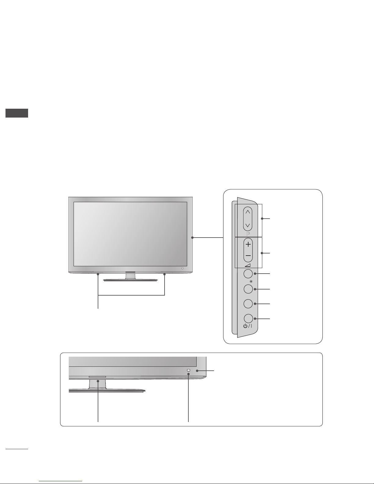
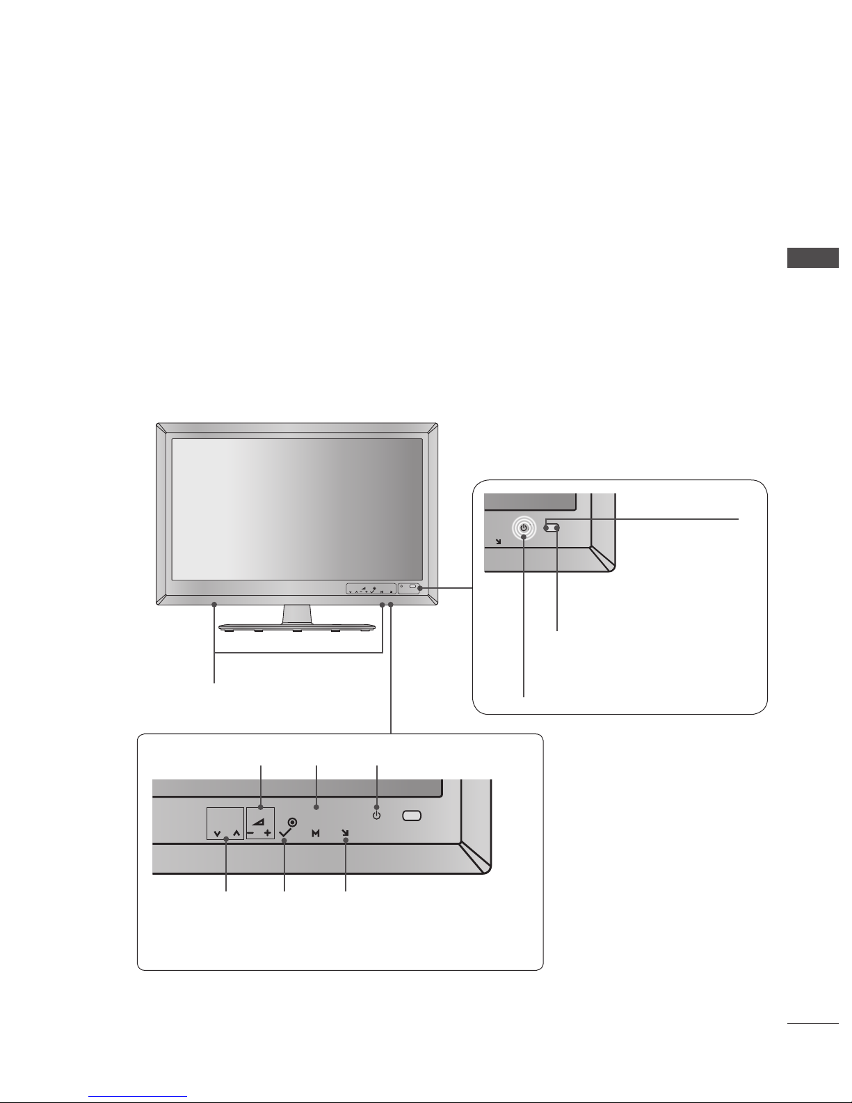
FRONT PANEL CONTROLS
NOTE :
TV can be placed in standby mode in order to reduce the power consumption. And TV should be switched off using the
power switch on the TV if it will not be watched for some time, as this will reduce energy consumption.
The energy consumed during use can be significantly reduced if the level of brightness of the picture is reduced, and this will
reduce the overall running cost.
CAUTION :
Do not step on the glass stand or subject it to any impact. It may break, causing possible injury from fragments of glass, or
the TV may fall.
Do not drag the TV. The floor or the product may be damaged.
Image shown may differ from your TV.
►
►
►
►
■
INPUT
MENU
OK
P
PROGRAMME
VOLUME
OK
Intelligent Sensor
Adjusts picture according to
the surrounding conditions.
OK
P
Power/Standby Indicator
• illuminates red in standby mode.
• illuminates blue when the TV is
switched on.
MENU
OK
P
MENU
INPUT
POWER
Remote Control Sensor
SPEAKER

GB-5
PREPARATION
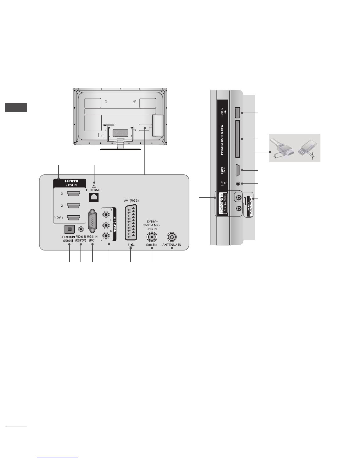
BACK PANEL INFORMATION
Image shown may differ from your TV.
Power Cord Socket
This TV operates on an AC power. The voltage is indicated on
the Specifications page. Never attempt to operate the TV on
DC power.
HDMI/DVI IN Input
Connect an HDMI signal to HDMI IN.
Or DVI(VIDEO) signal to HDMI/DVI port with DVI to HDMI
cable.
ETHERNET Input
Connect a LAN cable.
Component Input
Connect a component video/audio device to these jacks.
Euro Scart Socket (AV1)
Connect scart socket input or output from an external device
to these jacks.
OPTICAL DIGITAL AUDIO OUT
Connect digital audio to various types of equipment. Connect
to a Digital Audio Component. Use an Optical audio cable.
Note: In standby mode, these ports do not work.
RGB/DVI Audio Input
Connect the audio from a PC or DTV.
RGB IN Input
Connect the output from a PC.
Satellite LNB Input
Connect a satellite antenna cable.
Antenna Input
Connect a RF antenna or cable to this jack.
USB Input
Connect USB storage device to this jack.
PCMCIA (Personal Computer Memory Card
International Association) Card Slot
Insert the CI Module to PCMCIA CARD SLOT.
(This feature is not available in all countries.)
Headphone Socket
Plug the headphone into the headphone socket.
Audio/Video Input (AV2)
Connect audio/video output from an external device to these
jacks.
■
CABLE MANAGEMENT
AC IN
AV IN 2
L/MONO
R
AUDIO
VIDEO
USB IN
H/P
IN4
GB-6
PREPARATION
PREPARATION
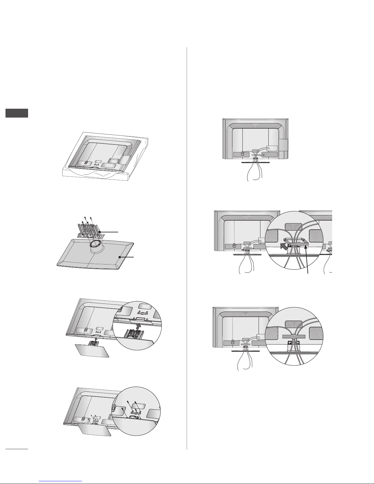
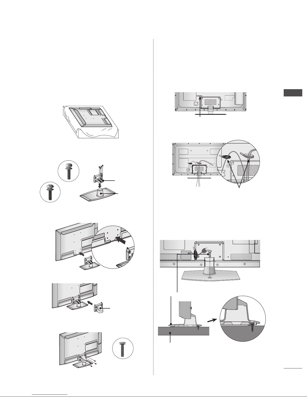
STAND INSTALLATION
Image shown may differ from your TV.
When assembling the desk type stand, check whether the bolt
is fully tightened. (If not tightened fully, the product can tilt
forward after the product installation.) If you tighten the bolt
with excessive force, the bolt can deviate from abrasion of the
tightening part of the bolt.
➊
Carefully place the TV screen side down on a cushioned
surface to protect the screen from damage.
➋
Assemble the parts of the Stand Body with the Stand
Base of the TV.
➌
Assemble the TV as shown.
➍
Fix the 4 bolts securely using the holes in the
back of the TV.
■
BACK COVER FOR WIRE
ARRANGEMENT
Image shown may differ from your TV.
➊
Connect the cables as necessary.
To connect additional equipment, see the External
Equipment Setup section.
➋
Install the CABLE MANAGEMENT CLIP as shown.
➌
Fit the CABLE MANAGEMENT CLIP as shown.
NOTE :
Do not use the Cable Management Clip to lift
the TV.
- If the TV is dropped, you may be injured or the TV may be
damaged.
►
■
AC IN
CABLE
MA
N
A
G
E
M
E
NT
Stand Body
Stand Base
AC IN
AC IN
AC IN
CABLE MANAGEMENT CLIP
AC I
N
CABLE
MANAGE
MENT
AC IN
CABLE
MA
N
A
G
E
M
E
NT
AC I
N
CABLE
MANAGE
MENT
CABLE
MA
N
A
G
E
M
E
NT
AC I
N
CABLE
MANAGE
MENT
AC IN
CABLE
MA
N
A
G
E
M
E
NT
AC IN
CABLE
MANAGEM
ENT
AC I
N
CABLE
MANAGE
MENT
AC IN
CABLE
MANAGEM
ENT
AC IN
AC IN
AC IN
AC IN
AC IN
AC IN
AC IN
AC IN
CABLE
MA
N
A
G
E
M
E
NT
GB-7
PREPARATION
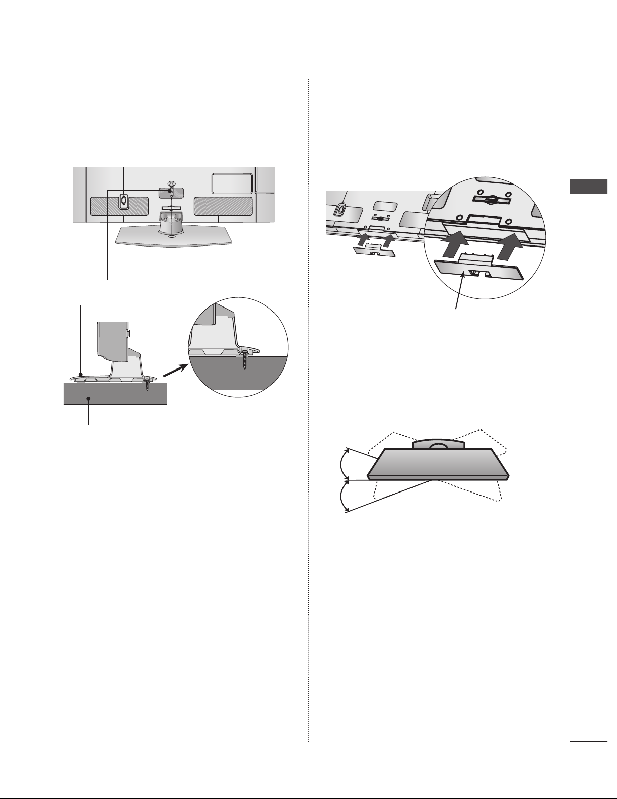
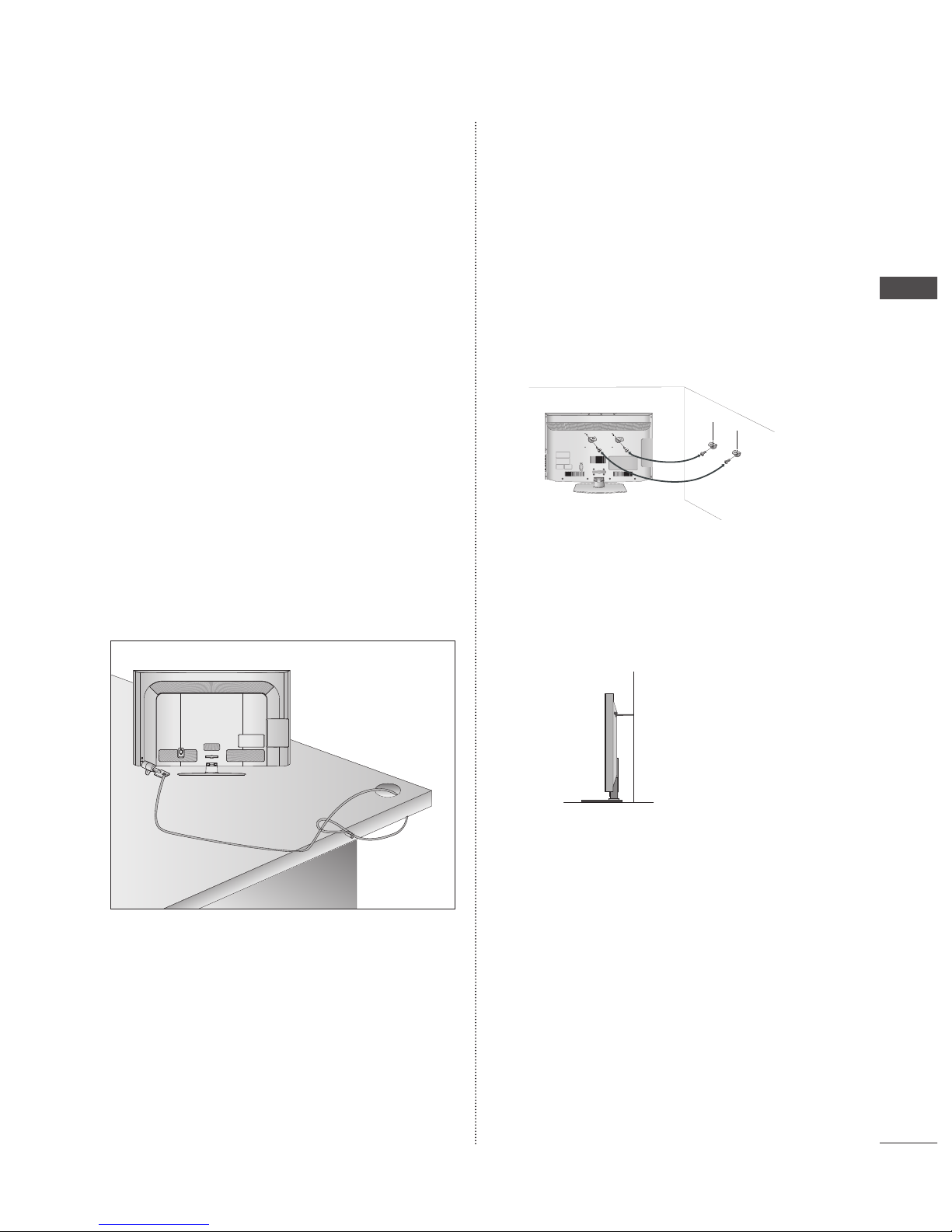
ATTACHING THE TV TO A DESK
Image shown may differ from your TV.
The TV must be attached to desk so it cannot be pulled in
a forward/backward direction, potentially causing injury or
damaging the product. Use only an attached screw.
WARNING
To prevent TV from falling over, the TV should be securely
attached to the floor/wall per installation instructions.
Tipping, shaking, or rocking the machine may cause
injury.
■
►
NOT USING THE DESKTYPE
STAND
Image shown may differ from your TV.
When installing the wall-mounted unit, use the protection cover.
Insert the Protection Cover into the TV until clicking sound.
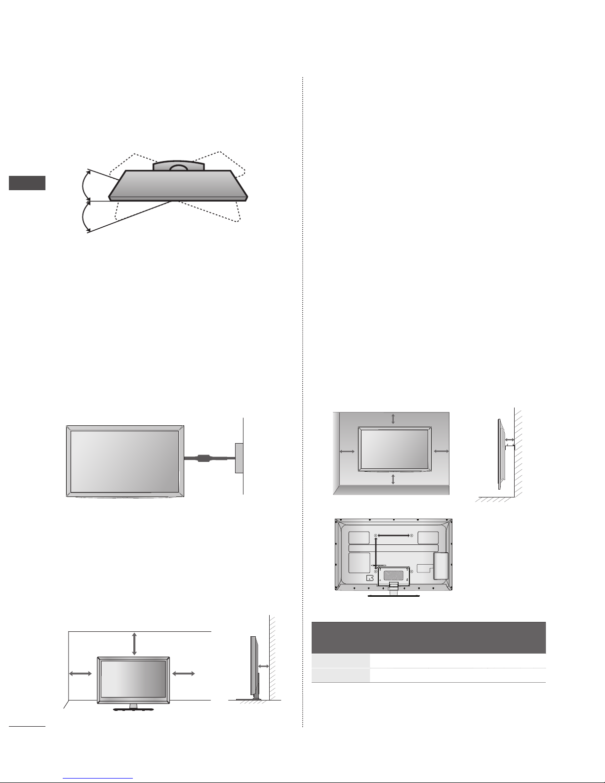
SWIVEL STAND
Image shown may differ from your TV.
After installing the TV, you can adjust the TV manually to the left or
right direction by 20 degrees to suit your viewing position.
■
■
CABLE MANAGEMENT
AC IN
1-Screw
( provided as parts of the product)
Stand
Desk
Protection Cover
GB-8
PREPARATION
PREPARATION
KENSINGTON SECURITY
SYSTEM
This feature is not available for all models.
Image shown may differ from your TV.
The TV is equipped with a Kensington Security System connector
on the back panel. Connect the Kensington Security System cable
as shown below.
For the detailed installation and use of the Kensington Security
System, refer to the user’s guide provided with the Kensington
Security System.
For further information, contact http://www.kensington. com,
the internet homepage of the Kensington company. Kensington
sells security systems for expensive electronic equipment such as
notebook PCs and LCD projectors.
NOTE
The Kensington Security System is an optional accessory.
If the TV feels cold to the touch, there may be a small
“flicker” when it is turned on. This is normal, there is
nothing wrong with TV.
Some minute dot defects may be visible on the screen,
appearing as tiny red, green, or blue spots. However, they
have no adverse effect on the monitor’s performance.
Avoid touching the LCD screen or holding your finger(s)
against it for long periods of time. Doing so may produce
some temporary distortion effects on the screen.
■
■
►
►
►
►
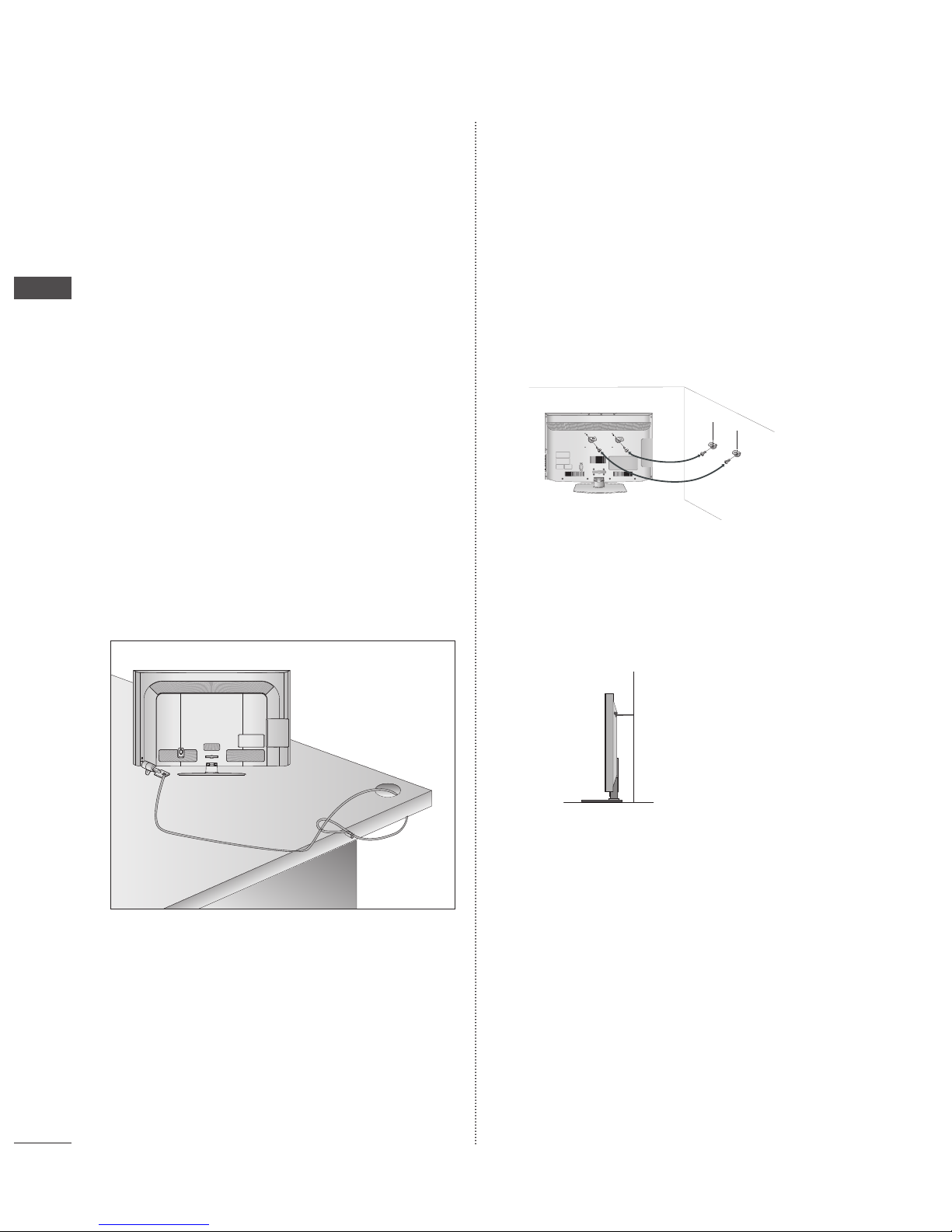
CAREFUL INSTALLATION
ADVICE
You should purchase necessary components to fix the TV
safety and secure to the wall on the market.
Position the TV close to the wall to avoid the possibility of
it falling when pushed.
The instructions shown below are a safer way to set up
the TV, by fixing it to the wall, avoiding the possibility of
it falling forwards if pulled. This will prevent the TV from
falling forward and causing injury. This will also prevent
the TV from damage. Ensure that
➊
Use the eye-bolts or TV brackets/bolts to fix the product to the
wall as shown in the picture.
(If your TV has bolts in the eyebolts, loosen these bolts.)
* Insert the eye-bolts or TV brackets/bolts and tighten them
securely in the upper holes.
➋
Secure the wall brackets with the bolts on the wall. Match the
height of the bracket that is mounted on the wall.
➌
Use a sturdy rope to tie the product for alignment. It is safer to
tie the rope so it becomes horizontal between the wall and the
product.
NOTE
When moving the TV undo the cords first.
Use a platform or cabinet strong and large enough to
support the size and weight of the TV.
To use the TV safely make sure that the height of the
bracket on the wall and on the TV is the same.
■
■
■
►
►
►
CABLE MANAGEMENT
AC IN
1
2
1
2
3
GB-9
PREPARATION
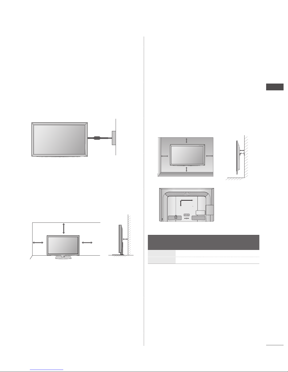
The TV can be installed in various ways such as on a wall,
or on a desktop etc.
The TV is designed to be mounted horizontally.
EARTHING
Ensure that you connect the earth wire to prevent possible electric
shock. If grounding methods are not possible, have a qualified
electrician install a separate circuit breaker.
Do not try to earth the TV by connecting it to telephone wires,
lightening rods or gas pipes.
DESKTOP PEDESTAL
INSTALLATION
Image shown may differ from your TV.
For adequate ventilation allow a clearance of 10 cm all around the
TV.
WALL MOUNT : HORIZONTAL
INSTALLATION
We recommend the use of a LG Brand wall mounting
bracket when mounting the TV to a wall.
We recommend that you purchase a wall mounting
bracket which supports VESA standard.
LG recommends that wall mounting be performed by a
qualified professional installer.
■
■
■
■
■
■
NOTE
Should Install wall mount on a solid wall perpendicular
to the floor.
Should use a special wall mount, if you want to install it
to ceiling or slanted wall.
The surface that wall mount is to be mounted on should
be of sufficient strength to support the weight of TV set;
e.g. concrete, natural rock, brick and hollow block.
Installing screw type and length depends on the wall
mount used. Further information, refer to the instructions
included with the mount.
LG is not liable for any accidents or damage to property
or TV due to incorrect installation:
- Where a non-compliant VESA wall mount is used.
- Incorrect fastening of screws to surface which may
cause TV to fall and cause personal injury.
- Not following the recommended Installation method.
Model
VESA
(A * B)
Standard
Screw
Quantity
32LD5
**
200 * 100 M4 4
42LD5
**
200 * 200 M6 4
►
►
►
►
►
10cm
10cm
10cm
10cm
10cm
10cm
10cm
10cm
10cm
10cm
10cm
10cm
10cm
10cm
CABLE MANAGEMENT
AC IN
A
B
Power Supply
Circuit breaker

GB-10
PREPARATION
PREPARATION
LED TV MODELS : 32/42LE5***
ACCESSORIES
Ensure that the following accessories are included with your TV. If an accessory is missing, please contact the dealer where you
purchased the TV.
Image shown may differ from your TV
Owner’s Manual Batteries (AAA) Remote Control
This item is not included for all models.
* Lightly wipe any stains or
fingerprints on the surface of the
TV with the polishing cloth.
Cable Holder
Polishing Cloth
Polishing cloth for use
on the screen.
Do not use excessive force. This may
cause scratching or discolouration.
Bolts for stand assembly
1-screw for stand fixing
(only 32LE5***)
Component gender cable,
AV gender cable
Wall Mounting Bracket (Seperate purchase)
■
P
A
G
E
P
1 2 3
4 506
7 8 9
LIST
Q.VIEW
AV MODE INPUT
TV/
RAD
ENERGY
SAVING
MARK
FAV
RATIO
MUTE
OK
MENU
GUIDE
Q.MENU
BACK
INFO
APP/
*
ADD
EXIT
P
A
G
E
P
1 2 3
4 506
7 8 9
LIST
Q.VIEW
AV MODE INPUT
TV/
RAD
ENERGY
SAVING
MARK
FAV
RATIO
MUTE
OK
MENU
GUIDE
Q.MENU
BACK
INFO
APP/
*
ADD
EXIT
P
A
G
E
P
1 2 3
4 506
7 8 9
LIST
Q.VIEW
AV MODE INPUT
TV/
RAD
ENERGY
SAVING
MARK
FAV
RATIO
MUTE
OK
MENU
GUIDE
Q.MENU
BACK
INFO
APP/
*
ADD
EXIT
P
A
G
E
P
1 2 3
4 506
7 8 9
LIST
Q.VIEW
AV MODE INPUT
TV/
RAD
ENERGY
SAVING
MARK
FAV
RATIO
MUTE
OK
MENU
GUIDE
Q.MENU
BACK
INFO
APP/
*
ADD
EXIT
P
A
G
E
P
1 2 3
4 506
7 8 9
LIST
Q.VIEW
AV MODE INPUT
TV/
RAD
ENERGY
SAVING
MARK
FAV
RATIO
MUTE
OK
MENU
GUIDE
Q.MENU
BACK
INFO
APP/
*
ADD
EXIT
LSW100B or
LSW100BG
32LE5*** 42LE5***
LSW200B or
LSW200BG
P
A
G
E
P
1 2 3
4 506
7 8 9
LIST
Q.VIEW
AV MODE INPUT
TV/
RAD
ENERGY
SAVING
MARK
FAV
RATIO
MUTE
OK
MENU
GUIDE
Q.MENU
BACK
INFO
APP/
*
ADD
EXIT
x 2
P
A
G
E
P
1 2 3
4 506
7 8 9
LIST
Q.VIEW
AV MODE INPUT
TV/
RAD
ENERGY
SAVING
MARK
FAV
RATIO
MUTE
OK
MENU
GUIDE
Q.MENU
BACK
INFO
APP/
*
ADD
EXIT
x 4 x 4
M4 x 22
(only 32LE5***)
M4 x 16
x 4
M4 x 24
(only 42LE5***)
P
A
G
E
P
1 2 3
4 506
7 8 9
LIST
Q.VIEW
AV MODE INPUT
TV/
RAD
ENERGY
SAVING
MARK
FAV
RATIO
MUTE
OK
MENU
GUIDE
Q.MENU
BACK
INFO
APP/
*
ADD
EXIT
GB-11
PREPARATION
FRONT PANEL CONTROLS
NOTE :
TV can be placed in standby mode in order to reduce the power consumption. And TV should be switched off using the
power switch on the TV if it will not be watched for some time, as this will reduce energy consumption.
The energy consumed during use can be significantly reduced if the level of brightness of the picture is reduced, and this will
reduce the overall running cost.
CAUTION :
Do not step on the glass stand or subject it to any impact. It may break, causing possible injury from fragments of glass, or
the TV may fall.
Do not drag the TV. The floor or the product may be damaged.
Image shown may differ from your TV.
►
►
►
►
■
P
OK
INPUT
MENU
/ I
PROGRAMME
VOLUME
OK
MENU
INPUT
POWER
Touch Sensor
• You can use the desired button function by touching.
Intelligent Sensor
Adjusts picture according to
the surrounding conditions.
INPUT
/ I
INPUT
/ I
Remote Control Sensor
Power/Standby Indicator
• illuminates red in standby mode.
• illuminates white when the TV is switched on.
P
OK
INPUT
MENU
/I
SPEAKER
GB-12
PREPARATION
PREPARATION
BACK PANEL INFORMATION
Image shown may differ from your TV.
HDMI/DVI IN Input
Connect an HDMI signal to HDMI IN.
Or DVI(VIDEO) signal to HDMI/DVI port with DVI to HDMI
cable.
ETHERNET Input
Connect a LAN cable.
OPTICAL DIGITAL AUDIO OUT
Connect digital audio to various types of equipment. Connect
to a Digital Audio Component. Use an Optical audio cable.
Note: In standby mode, these ports do not work.
RGB/DVI Audio Input
Connect the audio from a PC or DTV.
RGB IN Input
Connect the output from a PC.
Audio/Video Input (AV2/AV3)
Connect audio/video output from an external device to these
jacks.
Euro Scart Socket (AV1)
Connect scart socket input or output from an external device
to these jacks.
Satellite LNB Input
Connect a satellite antenna cable.
Antenna Input
Connect a RF antenna or cable to this jack.
USB Input
Connect USB storage device to this jack.
PCMCIA (Personal Computer Memory Card
International Association) Card Slot
Insert the CI Module to PCMCIA CARD SLOT.
(This feature is not available in all countries.)
Headphone Socket
Plug the headphone into the headphone socket.
Component Input
Connect a component video/audio device to these jacks.
■
USB IN
H/P
IN 4
COMPONENT IN
Y
/ AUDIO
CAUTION
Use a product with the
following thickness for
optimal connection
to HDMI cable (Only
HDMI IN 4) /USB
device.
*A≤10 mm
►
GB-13
PREPARATION
STAND INSTALLATION
Image shown may differ from your TV.
When assembling the desk type stand, check whether the bolt
is fully tightened. (If not tightened fully, the product can tilt
forward after the product installation.) If you tighten the bolt
with excessive force, the bolt can deviate from abrasion of the
tightening part of the bolt.
➊
Carefully place the TV screen side down on a cushioned
surface to protect the screen from damage.
➋
Assemble the parts of the Stand Body with the Stand
Base of the TV.
➌
Assemble the TV as shown.
➍
Assemble the parts of the Stand Rear Cover with the TV.
➎
Fix the 4 bolts securely using the holes in the back of the
TV.
■
BACK COVER FOR WIRE
ARRANGEMENT
Image shown may differ from your TV.
➊
Secure the power cord with the Cable Holder on the TV
back cover.It will help prevent the power cable from being
removed by accident.
➋
After connecting the cables as necessary,install Cable
Holder as shown and bundle the cables.
ATTACHING THE TV TO A DESK
Image shown may differ from your TV.
The TV must be attached to desk so it cannot be pulled in
a forward/backward direction, potentially causing injury or
damaging the product. Use only an attached screw.
WARNING
To prevent TV from falling over, the TV should be securely
attached to the floor/wall per installation instructions.
Tipping, shaking, or rocking the machine may cause
injury.
■
■
►
M4 x 22
M4 x 24
Stand Rear
Cover
Cable Holder
Cable Holder
M4 x 22
M4 x 24
M4 x 22
M4 x 24
M4 x 16
M4 x 22
M4 x 24
M4 x 22
M4 x 24
(only 32LE5***)
Stand Base
(only 42LE5***)
Stand Body
1-Screw
( provided as parts of the product)
Stand
Desk
GB-14
PREPARATION
PREPARATION
SWIVEL STAND
Image shown may differ from your TV.
After installing the TV, you can adjust the TV manually to the left or
right direction by 20 degrees to suit your viewing position.
The TV can be installed in various ways such as on a wall,
or on a desktop etc.
The TV is designed to be mounted horizontally.
EARTHING
Ensure that you connect the earth wire to prevent possible electric
shock. If grounding methods are not possible, have a qualified
electrician install a separate circuit breaker.
Do not try to earth the TV by connecting it to telephone wires,
lightening rods or gas pipes.
DESKTOP PEDESTAL
INSTALLATION
Image shown may differ from your TV.
For adequate ventilation allow a clearance of 10 cm all around the
TV.
■
■
■
■
WALL MOUNT : HORIZONTAL
INSTALLATION
We recommend the use of a LG Brand wall mounting
bracket when mounting the TV to a wall.
We recommend that you purchase a wall mounting
bracket which supports VESA standard.
LG recommends that wall mounting be performed by a
qualified professional installer.
NOTE
Should Install wall mount on a solid wall perpendicular
to the floor.
Should use a special wall mount, if you want to install it
to ceiling or slanted wall.
The surface that wall mount is to be mounted on should
be of sufficient strength to support the weight of TV set;
e.g. concrete, natural rock, brick and hollow block.
Installing screw type and length depends on the
wall mount used. Further information, refer to the
instructions included with the mount.
LG is not liable for any accidents or damage to property
or TV due to incorrect installation:
- Where a non-compliant VESA wall mount is used.
- Incorrect fastening of screws to surface which may
cause TV to fall and cause personal injury.
- Not following the recommended Installation method.
Model
VESA
(A * B)
Standard
Screw
Quantity
32LE5
***
200 * 100 M4 4
42LE5
***
200 * 200 M6 4
■
■
■
►
►
►
►
►
10cm
10cm
10cm
10cm
Power Supply
Circuit breaker
10cm
10cm
10cm
10cm
10cm
10cm
10cm
10cm
10cm
10cm
A
B
GB-15
PREPARATION
KENSINGTON SECURITY
SYSTEM
This feature is not available for all models.
Image shown may differ from your TV.
The TV is equipped with a Kensington Security System connector
on the back panel. Connect the Kensington Security System cable
as shown below.
For the detailed installation and use of the Kensington Security
System, refer to the user’s guide provided with the Kensington
Security System.
For further information, contact http://www.kensington. com,
the internet homepage of the Kensington company. Kensington
sells security systems for expensive electronic equipment such as
notebook PCs and LCD projectors.
NOTE
The Kensington Security System is an optional accessory.
If the TV feels cold to the touch, there may be a small
“flicker” when it is turned on. This is normal, there is
nothing wrong with TV.
Some minute dot defects may be visible on the screen,
appearing as tiny red, green, or blue spots. However, they
have no adverse effect on the monitor’s performance.
Avoid touching the LCD screen or holding your finger(s)
against it for long periods of time. Doing so may produce
some temporary distortion effects on the screen.
■
■
►
►
►
►
CAREFUL INSTALLATION
ADVICE
You should purchase necessary components to fix the TV
safety and secure to the wall on the market.
Position the TV close to the wall to avoid the possibility of
it falling when pushed.
The instructions shown below are a safer way to set up
the TV, by fixing it to the wall, avoiding the possibility of
it falling forwards if pulled. This will prevent the TV from
falling forward and causing injury. This will also prevent
the TV from damage. Ensure that
➊
Use the eye-bolts or TV brackets/bolts to fix the product to the
wall as shown in the picture.
(If your TV has bolts in the eyebolts, loosen these bolts.)
* Insert the eye-bolts or TV brackets/bolts and tighten them
securely in the upper holes.
➋
Secure the wall brackets with the bolts on the wall. Match the
height of the bracket that is mounted on the wall.
➌
Use a sturdy rope to tie the product for alignment. It is safer to
tie the rope so it becomes horizontal between the wall and the
product.
NOTE
When moving the TV undo the cords first.
Use a platform or cabinet strong and large enough to
support the size and weight of the TV.
To use the TV safely make sure that the height of the
bracket on the wall and on the TV is the same.
■
■
■
►
►
►
CABLE MANAGEMENT
AC IN
1
2
1
2
3

GB-16
EXTERNAL EQUIPMENT SETUP
To prevent damage do not connect to the mains outlet until all connections are made between the devices.
This section mainly uses diagrams for the 32/42LD5** models.
Antenna Connection
For optimum picture quality, adjust antenna direction.
An antenna cable and converter are not supplied.
In poor signal areas, to achieve better picture quality it may be necessary to install a signal amplifier to the antenna as
shown above.
If signal needs to be split for two TVs, use an antenna signal splitter for connection.
■
■
■
■
■
■
EXTERNAL EQUIPMENT SETUP
AV IN 2
L/MONO
R
AUDIO
VIDEO
USB IN
H/P
IN4
AV IN 2
L/MONO
R
AUDIO
VIDEO
USB IN
H/P
IN4
CABLE MANAGEMENT
AC IN
USB IN
Satellite
Dish
Terrestrial
Antenna
Satellite RF Coaxial Cable (75 ohm)
Terrestrial RF Coaxial Cable (75 ohm)
AV IN 2
L/MONO
R
AUDIO
VIDEO
USB IN
H/P
IN4
UHF
VHF
Signal
Amplifier
Terrestrial
Antenna
GB-17
EXTERNAL EQUIPMENT SETUP
To avoid damaging any equipment, never plug in any power cord until you have finished connecting all equipment.
Image shown may differ from your TV.
HD RECEIVER SETUP
This TV can receive Digital RF/Cable signals without an external digital set-top box. However, if you do receive Digital signals
from a digital set-top box or other digital external device, refer to the diagram as shown below.
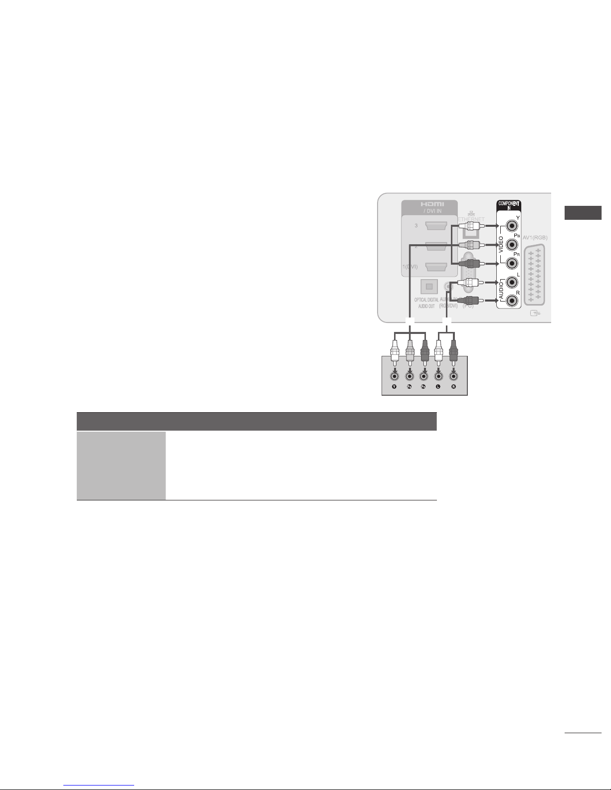
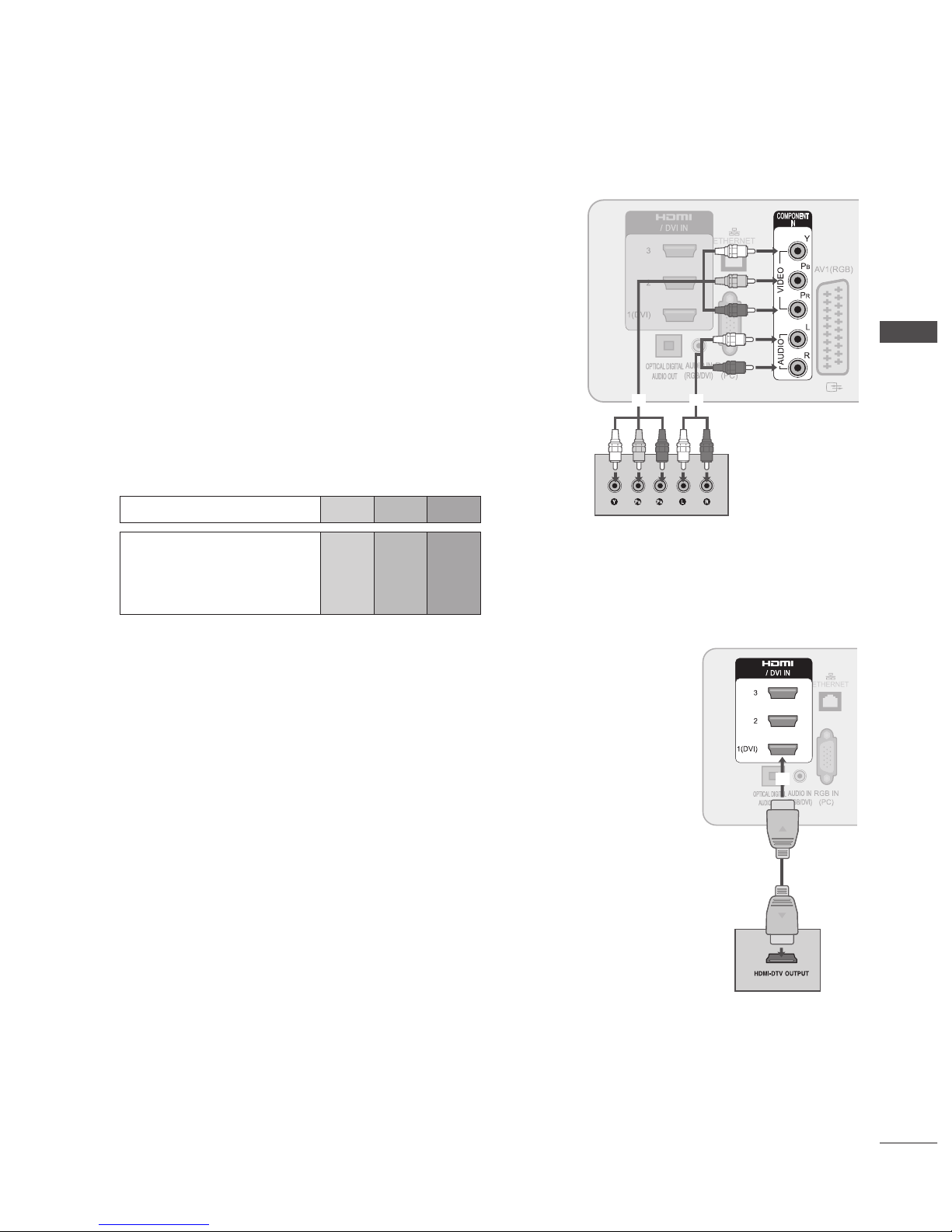
Connecting with a Component Cable
➊
Connect the video outputs (Y, PB, PR) of the digital set top box to the
COMPONENT IN VIDEO jacks on the TV.
➋
Connect the audio outputs of the digital set-top box to the COMPONENT IN
AUDIO jacks on the TV.
➌
Turn on the digital set-top box. (Refer to the owner’s manual for the digital settop box.)
➍
Select Component input source using the INPUT button on the remote
control.
Signal Component HDMI
480i/576i O X
480p/576p O O
720p/1080i O O
1080p
O
(50/60Hz only)
O
(24Hz/30Hz/50Hz/60Hz)
■
■
■
➊
➋
GB-18
EXTERNAL EQUIPMENT SETUP
EXTERNAL EQUIPMENT SETUP
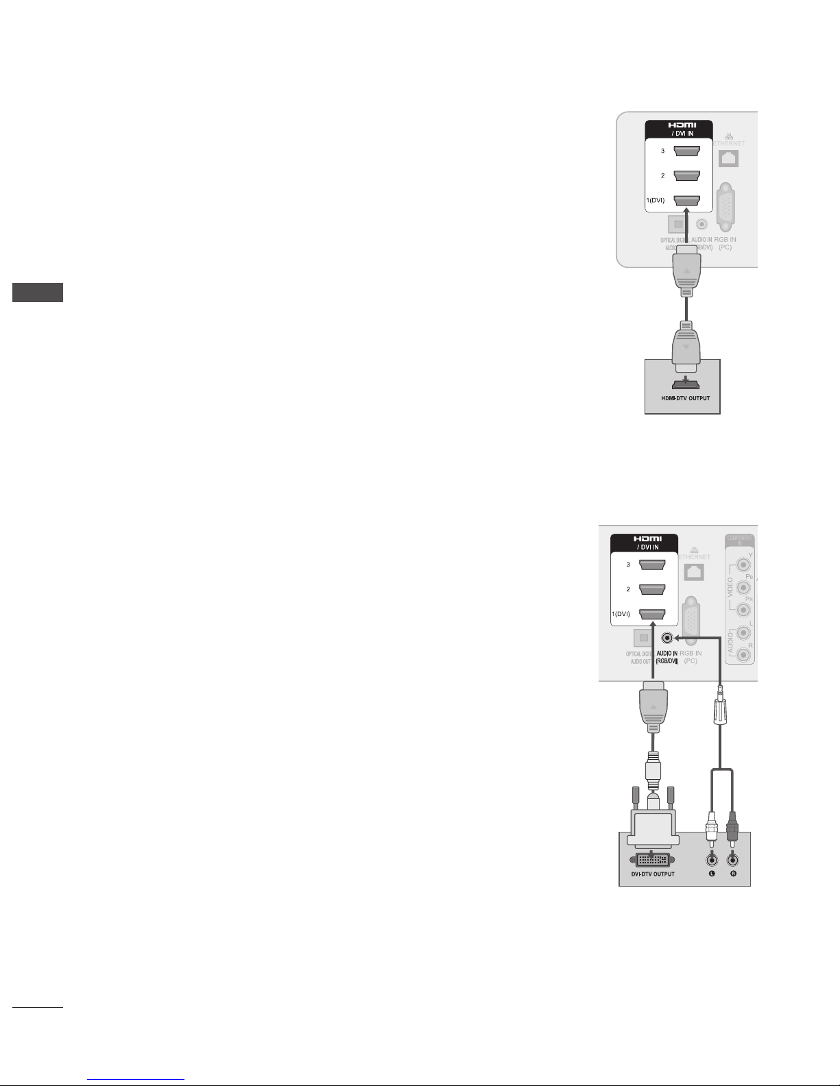
Connecting with an HDMI Cable
➊
Connect the digital set-top box to HDMI/DVI IN 1, HDMI IN 2, HDMI IN 3 or HDMI IN 4 jack
on the TV.
➋
Turn on the digital set-top box.
(Refer to the owner’s manual for the digital set-top box.)
➌
Select HDMI1, HDMI2, HDMI3 or HDMI4 input source using the INPUT button on the
remote control.
NOTE
Check that your HDMI cable is version 1.3 or higher. If the HDMI cables don’t support HDMI
version 1.3, flickering or no screen display can result. Please use the latest cables that support
at least HDMI version 1.3.
HDMI Audio Supported format : Dolby Digital, PCM
(DTS Audio format is not supported).
Connecting with an HDMI to DVI Cable
➊
Connect the digital set-top box to HDMI/DVI IN 1 jack on the TV.
➋
Connect the audio output of the digital set-top box to the AUDIO IN (RGB/DVI) jack on the TV.
➌
Turn on the digital set-top box.
(Refer to the owner’s manual for the digital set-top box.)
➍
Select HDMI 1 input source using the INPUT button on the remote control.
►
►
GB-19
EXTERNAL EQUIPMENT SETUP
DVD SETUP
Connecting with a Component Cable
➊
Connect the video outputs (Y, PB, PR) of the DVD to the COMPONENT IN
VIDEO jacks on the TV.
➋
Connect the audio outputs of the DVD to the COMPONENT IN AUDIO jacks
on the TV.
➌
Turn on the DVD player, insert a DVD.
➍
Select Component input source using the INPUT button on the remote
control.
➎
Refer to the DVD player’s manual for operating instructions.
Component Input Ports
To achieve better picture quality, connect a DVD player to the component input
ports as shown below.
Component ports on the TV Y PB PR
Video output ports
on DVD player
Y
Y
Y
Y
PB
B-Y
Cb
Pb
PR
R-Y
Cr
Pr
Connecting the HDMI Cable
➊
Connect the HDMI output of the DVD to the HDMI/DVI IN 1, HDMI IN 2, HDMI IN 3 or
HDMI IN 4 jack on the TV.
➋
Select HDMI1, HDMI2, HDMI3 or HDMI4 input source using the INPUT button on the
remote control.
➌
Refer to the DVD player’s manual for operating instructions.
NOTE
The TV can receive video and audio signals simultaneously when using a HDMI cable.
If the DVD does not support Auto HDMI, you must set the output resolution appropriately.
Check that your HDMI cable is version 1.3 or higher. If the HDMI cables don’t support HDMI
version 1.3, flickering or no screen display can result. Please use the latest cables that
support at least HDMI version 1.3.
►
►
►
➊
➊
➋

GB-20
EXTERNAL EQUIPMENT SETUP
EXTERNAL EQUIPMENT SETUP
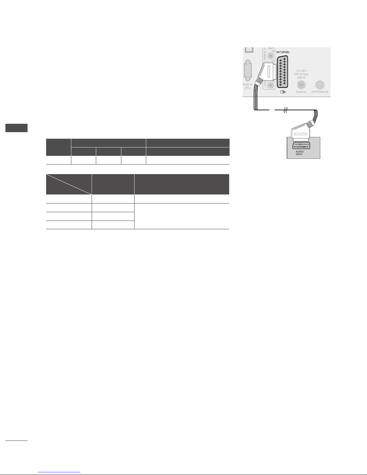
Connecting with a Euro Scart Cable
➊
Connect the Euro scart socket of the DVD to the AV1 Euro scart socket on the TV.
➋
Turn on the DVD player, insert a DVD.
➌
Select AV1 input source using the INPUT button on the remote control.
➍
Refer to the DVD player’s manual for operating instructions.
NOTE
Any Euro scart cable used must be signal shielded.
Copy-protected programmes will not be output on the EURO scart sockets for legal
reasons. Even if it was output, the video signals fed through the EURO scart sockets
will be not recorded by copyright protection systems.
Scart
Input Output
Video Audio RGB Video, Audio
AV1 O O O Analogue TV, Digital TV
Output Type
Current
input model
AV1
(TV Out)
AV1
(When DTV scheduled recording is in
progress using recording equipment.)
Digital TV Digital TV O
Analogue TV, AV Analogue TV
O
(The input mode is converted to DTV.)
Component/RGB Analogue TV
HDMI Analogue TV
►
►
➊
GB-21
EXTERNAL EQUIPMENT SETUP
VCR SETUP
To
avoid picture noise (interference), allow adequate distance between the VCR and TV.
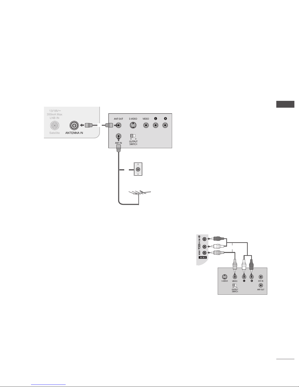
Connecting with a RF Cable
➊
Connect the ANT OUT socket of the VCR to the ANTENNA IN socket on the TV.
➋
Connect the terrestrial antenna cable to the ANT IN socket of the VCR.
➌
Press the PLAY button on the VCR and match the appropriate channel between the TV and VCR for viewing.
Connecting with a RCA Cable
➊
Connect the AUDIO/VIDEO jacks between TV and VCR. Match the jack colours
(Video = yellow, Audio Left = white, and Audio Right = red)
➋
Insert a video tape into the VCR and press PLAY on the VCR. (Refer to the VCR
owner’s manual.)
➌
Select AV2 input source using the INPUT button on the remote control.
NOTE
If you have a mono VCR, connect the audio cable from the VCR to the AUDIO
L/MONO jack of the TV.
►
AV IN 2
L/MONO
R
AUDIO
VIDEO
H/P
IN4
➊
Terrestrial
Wall jack
Terrestrial Antenna
➊
➋
GB-22
EXTERNAL EQUIPMENT SETUP
EXTERNAL EQUIPMENT SETUP
Connecting with a Euro Scart Cable
➊
Connect the Euro scart socket of the VCR to the AV1 Euro scart socket on the TV.
➋
Insert a video tape into the VCR and press PLAY on the VCR.
(Refer to the VCR owner’s manual.)
➌
Select AV1 input source using the INPUT button on the remote control.
NOTE
Any Euro Scart cable used must be signal shielded.
Copy-protected programmes will not be output on the EURO scart sockets for legal
reasons. Even if it was output, the video signals fed through the EURO scart sockets
will be not recorded by copyright protection systems.
Scart
Input Output
Video Audio RGB Video, Audio
AV1 O O O Analogue TV, Digital TV
Output Type
Current
input model
AV1
(TV Out)
AV1
(When DTV scheduled recording is in
progress using recording equipment.)
Digital TV Digital TV O
Analogue TV, AV Analogue TV
O
(The input mode is converted to DTV.)
Component/RGB Analogue TV
HDMI Analogue TV
►
►
➊

GB-23
EXTERNAL EQUIPMENT SETUP
INSERTION OF CI MODULE
- To view the encrypted (pay) services in digital TV mode.
- This feature is not available in all countries.
➊
Insert the CI Module to PCMCIA (Personal Computer Memory Card International
Association) CARD SLOT of TV as shown.
For further information, see p.49.
NOTE
Check if the CI module is inserted into the PCMCIA card slot in the right direction. If the
module is not inserted properly, this can cause damage to the TV and the PCMCIA card
slot.
DIGITAL AUDIO OUT SETUP
Sending the TV’s digital audio signal to external audio equipment via the Digital Audio
Output (Optical) port.
If you want to enjoy digital broadcasting through 5.1-channel speakers, connect the
OPTICAL DIGITAL AUDIO OUT terminal on the back of TV to a Home Theater (or amp).
➊
Connect one end of an optical cable to the TV Digital Audio (Optical) Output port.
➋
Connect the other end of the optical cable to the digital audio (Optical) input on the
audio equipment.
➌
Set the “TV Speaker - Off ” in the AUDIO menu.(up.101). Refer to the external audio
equipment instruction manual for operation.
CAUTION
Do not look into the optical output port. Looking at the laser beam may damage your
vision.
HEADPHONE SETUP
You can listen the sound through the headphone.
➊
Plug the headphone into the headphone socket.
➋
To adjust the headphone volume, press the + or - button.
If you press the MUTE button, the sound from the headphone is switched
off.
NOTE
AUDIO menu items are disabled when connecting a headphone.
When changing AV MODE with a headphone connected, the change is applied to video but not to audio.
Optical Digital Audio Out is not available when connecting a headphone.
Headphone impedance: 16 Ω
Max audio output of headphone: 10 mW to 15 mW
►
►
►
►
►
►
►
AUDIO
USB IN
H/P
IN4
➊
USB IN
H/P
IN4
➊
Check this point as
shown and insert the
CI Module.
GB-24
EXTERNAL EQUIPMENT SETUP
EXTERNAL EQUIPMENT SETUP
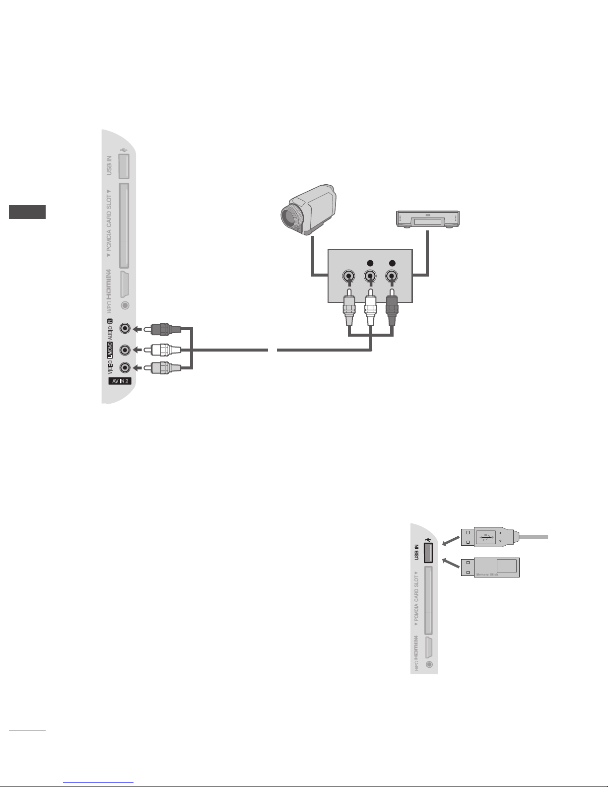
OTHER A/V SOURCE SETUP
➊
Connect the AUDIO/VIDEO jacks between TV and external equipment. Match the jack colours. (Video = yellow, Audio Left =
white, and Audio Right = red)
➋
Select AV2 input source using the INPUT button on the remote control.
➌
Operate the corresponding external equipment.
(Refer to external equipment operating guide.)
USB SETUP
➊
Connect the USB device to the USB IN jack on the side of the TV.
➋
After connecting the USB IN jack, you use the USB function. (up.57)
AV IN 2
L/MONO
R
AUDIO
VIDEO
H/P
IN4
L R
VIDEO
Camcorder
Video Game Set
➊
USB IN
H/P
IN4
➊

GB-25
EXTERNAL EQUIPMENT SETUP
PC SETUP
This TV provides Plug and Play capability, meaning that the PC adjusts automatically to the TV’s settings.
Connecting with a D-sub 15 pin Cable
➊
Connect the RGB output of the PC to the RGB IN (PC) jack on the TV.
➋
Connect the PC audio output to the AUDIO IN (RGB/DVI) jack on the TV.
➌
Turn on the PC and the TV.
➍
Select RGB input source using the INPUT button on the remote control.
Connecting with an HDMI to DVI Cable
➊
Connect the DVI output of the PC to the HDMI/DVI IN 1 jack on the TV.
➋
Connect the PC audio output to the AUDIO IN (RGB/DVI) jack on the TV.
➌
Turn on the PC and the TV.
➍
Select HDMI 1 input source using the INPUT button on the remote control.
➊
➋
➊
➋

GB-26
EXTERNAL EQUIPMENT SETUP
EXTERNAL EQUIPMENT SETUP
Supported Display Resolution
RGB(PC), HDMI1(DVI) -PC mode
Resolution
Horizontal
Frequency(kHz)
Vertical
Frequency(Hz)
720 x 400 31.468 70.08
640 x 480 31.469 59.94
800 x 600 37.879 60.31
1024 x 768 48.363 60.00
1280 x 768 47.78 59.87
1360 x 768 47.72 59.80
1280 x 1024 63.98 60.02
1400 x 1050 65.317 59.979
1920 x 1080 66.587 59.937
HDMI1, HDMI2, HDMI3, HDMI4 -DTV mode
Resolution
Horizontal
Frequency(kHz)
Vertical
Frequency(Hz)
640 x 480
31.649
31.469
59.94
60
720 x 480
31.47
31.50
59.94
60
720 x 576 31.25 50.00
1280 x 720
37.50
44.96
45.00
50.00
59.94
60
1920 x 1080
28.125
33.72
33.75
27.00
33.750
56.25
67.433
67.50
50.00
59.94
60
24.00
30
50.00
59.94
60
Component mode
Resolution
Horizontal
Frequency(kHz)
Vertical
Frequency(Hz)
720 x 480
15.73
15.75
31.47
31.50
59.94
60
59.9
60
720 x 576
15.6
31.25
50
50
1280 x 720
37.50
44.96
45.00
50.00
59.94
60.00
1920 x 1080
33.72
33.75
28.125
56.25
67.433
67.500
59.94
60.00
50.00
50.00
59.94
60.00
NOTE :
Avoid keeping a fixed image on the TV’s screen for prolonged periods of time. The fixed image may become permanently
imprinted on the screen; use a screen saver when possible.
There may be interference relating to resolution, vertical pattern, contrast or brightness in PC mode. Change the PC mode
to another resolution or change the refresh rate to another rate or adjust the brightness and contrast on the menu until
the picture is clear. If the refresh rate of the PC graphic card can not be changed, change the PC graphic card or consult the
manufacturer of the PC graphic card.
The synchronization input waveform for Horizontal and Vertical frequencies are separate.
We recommend using 1920 x 1080, 60Hz for the PC mode, this should provide the best picture quality.
Connect the signal cable from the monitor output port of the PC to the RGB IN(PC) port of the TV or the signal cable from the
HDMI output port of the PC to the HDMI/DVI IN 1(DVI) port on the TV.
Connect the audio cable from the PC to the AUDIO IN (RGB/DVI) on the TV. (Audio cables are not included with the TV).
If using a sound card, adjust PC sound as required.
If the graphic card on the PC does not output analogue and digital RGB simultaneously, connect only one of either RGB IN or
HDMI/DVI IN 1(DVI) to display the PC output on the TV.
If the graphic card on the PC does output analogue and digital RGB simultaneously, switch the TV to either RGB or HDMI; (the
other mode is set to Plug and Play automatically by the TV.)
DOS mode may not work depending on the video card if you use a HDMI to DVI cable.
If you use too long an RGB-PC cable, there may be interference on the screen. We recommend using under 5m of cable. This
provides the best picture quality.
►
►
►
►
►
►
►
►
►
►
►
GB-27
EXTERNAL EQUIPMENT SETUP
Screen Setup for PC mode (In RGB mode only)
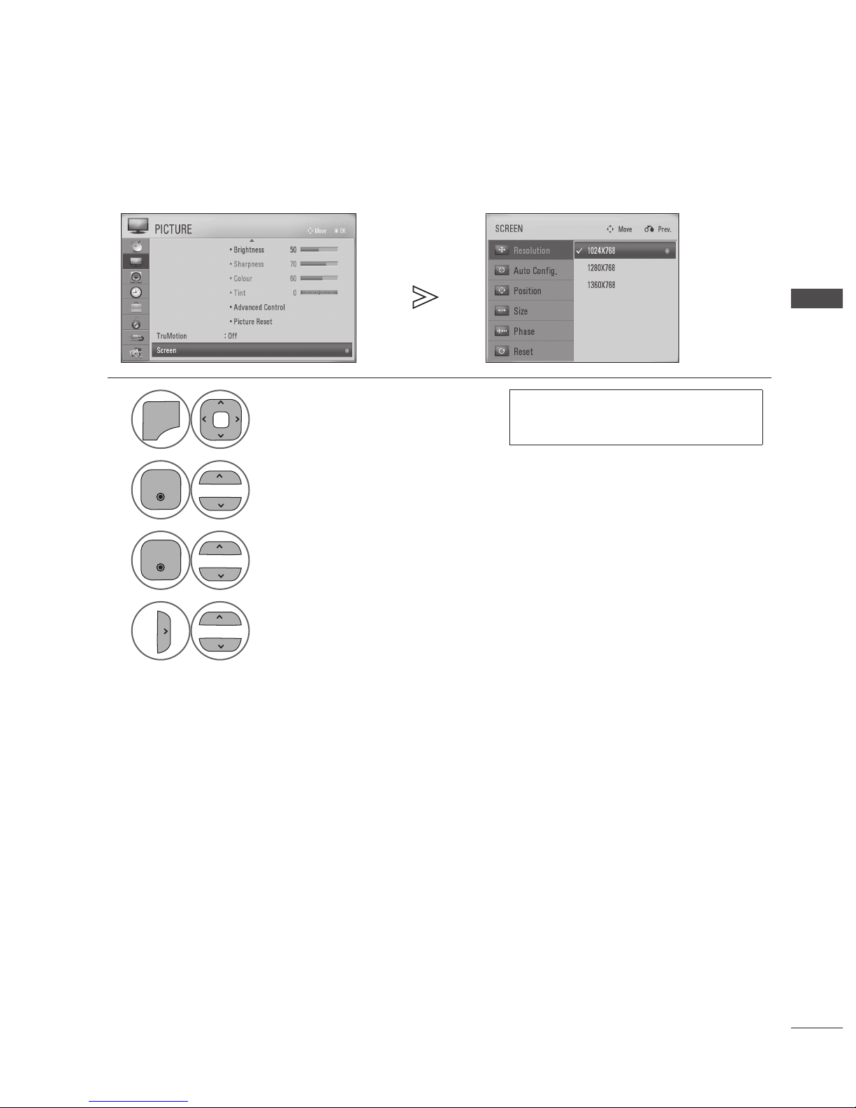
Selecting Resolution
To view a normal picture, match the resolution of RGB mode and resolution of PC.
1
P
A
G
E
P
1 2 3
4 506
7 8 9
LIST
Q.VIEW
INPUT
ENERGY
SAVING
MARK
FAV
MARK
FAV
RATIO
MUTE
AV MODE
MENU
GUIDE
Q.MENU
TV/
RAD
P
A
G
E
P
1 2 3
4 506
7 8 9
LIST
Q.VIEW
INPUT
ENERGY
SAVING
MARK
FAV
MARK
FAV
RATIO
MUTE
AV MODE
MENU
GUIDE
Q.MENU
TV/
RAD
Select PICTURE.
• The Resolution menu is disabled unless the
resolution is set to 1024 x 768, 1280 x 768 or
1360 x 768.
2
P
A
G
E
P
Q.VIEW
INPUT
ENERGY
SAVING
RATIO
MUTE
OK
AV MODE
Q.MENU
BACK
INFO
TV/
RAD
EXIT
P
A
G
E
P
Q.VIEW
INPUT
ENERGY
SAVING
RATIO
MUTE
AV MODE
Q.MENU
TV/
RAD
Select Screen.
3
P
A
G
E
P
Q.VIEW
INPUT
ENERGY
SAVING
RATIO
MUTE
OK
AV MODE
Q.MENU
BACK
INFO
TV/
RAD
EXIT
P
A
G
E
P
Q.VIEW
INPUT
ENERGY
SAVING
RATIO
MUTE
AV MODE
Q.MENU
TV/
RAD
Select Resolution.
4
P
A
G
E
P
LIST
Q.VIEW
INPUT
ENERGY
SAVING
MARK
FAV
RATIO
MUTE
OK
AV MODE
GUIDE
Q.MENU
BACK
INFO
TV/
RAD
EXIT
P
A
G
E
P
Q.VIEW
INPUT
ENERGY
SAVING
RATIO
MUTE
AV MODE
Q.MENU
TV/
RAD
Select the desired resolution.
• Press the MENU/EXIT button to return to normal TV viewing.
• Press the BACK button to return to the previous screen.
GB-28
EXTERNAL EQUIPMENT SETUP
EXTERNAL EQUIPMENT SETUP
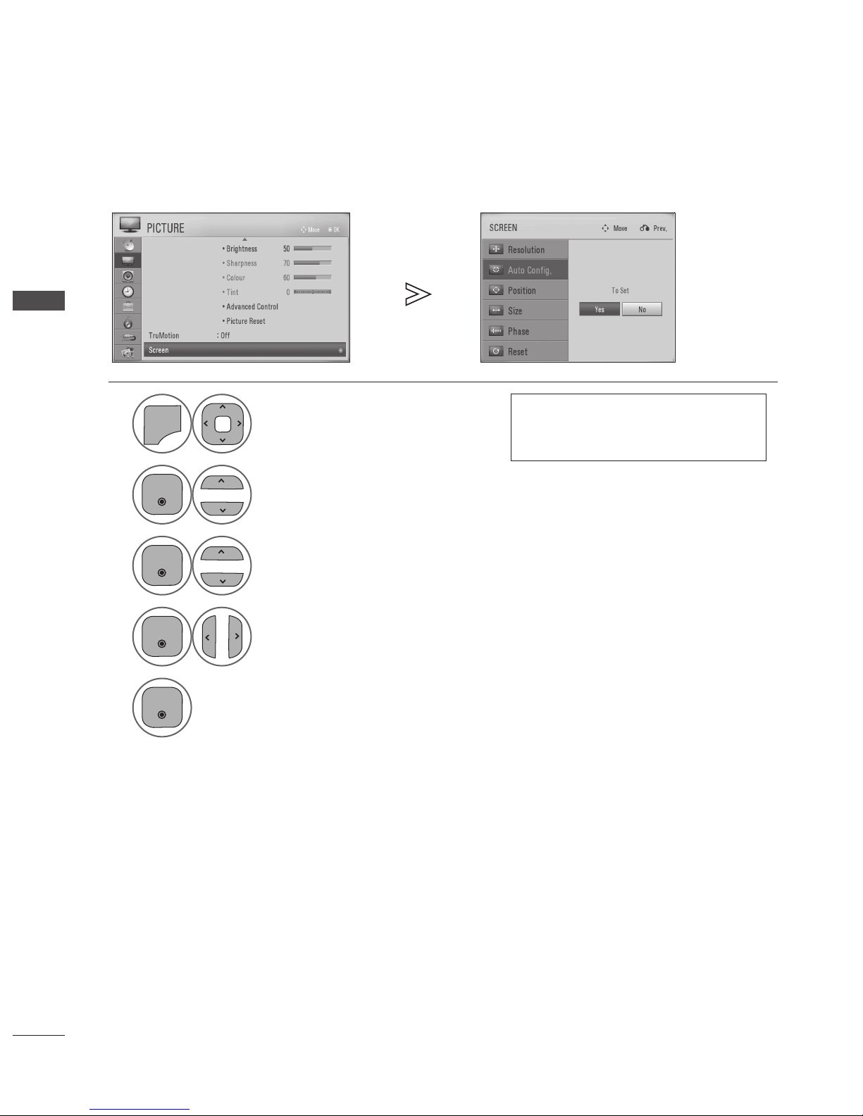
Auto Congure
Automatically optimizes the display. This is recommended for the first time connecting to a PC.
1
P
A
G
E
P
1 2 3
4 506
7 8 9
LIST
Q.VIEW
INPUT
ENERGY
SAVING
MARK
FAV
MARK
FAV
RATIO
MUTE
AV MODE
MENU
GUIDE
Q.MENU
TV/
RAD
P
A
G
E
P
1 2 3
4 506
7 8 9
LIST
Q.VIEW
INPUT
ENERGY
SAVING
MARK
FAV
MARK
FAV
RATIO
MUTE
AV MODE
MENU
GUIDE
Q.MENU
TV/
RAD
Select PICTURE.
• If the picture is not clear after auto
configuration, adjust the position, size or
phase of picture manually.
2
P
A
G
E
P
Q.VIEW
INPUT
ENERGY
SAVING
RATIO
MUTE
OK
AV MODE
Q.MENU
BACK
INFO
TV/
RAD
EXIT
P
A
G
E
P
Q.VIEW
INPUT
ENERGY
SAVING
RATIO
MUTE
AV MODE
Q.MENU
TV/
RAD
Select Screen.
3
P
A
G
E
P
Q.VIEW
INPUT
ENERGY
SAVING
RATIO
MUTE
OK
AV MODE
Q.MENU
BACK
INFO
TV/
RAD
EXIT
P
A
G
E
P
Q.VIEW
INPUT
ENERGY
SAVING
RATIO
MUTE
AV MODE
Q.MENU
TV/
RAD
Select Auto Cong..
4
P
A
G
E
P
Q.VIEW
INPUT
ENERGY
SAVING
RATIO
MUTE
OK
AV MODE
Q.MENU
BACK
INFO
TV/
RAD
EXIT
P
A
G
E
P
LIST
Q.VIEW
INPUT
ENERGY
SAVING
MARK
FAV
RATIO
MUTE
AV MODE
GUIDE
Q.MENU
TV/
RAD
Select Yes.
5
P
A
G
E
P
Q.VIEW
INPUT
ENERGY
SAVING
RATIO
MUTE
OK
AV MODE
Q.MENU
BACK
INFO
TV/
RAD
EXIT
Run Auto Cong..
• Press the MENU/EXIT button to return to normal TV viewing.
• Press the BACK button to return to the previous screen.
GB-29
EXTERNAL EQUIPMENT SETUP
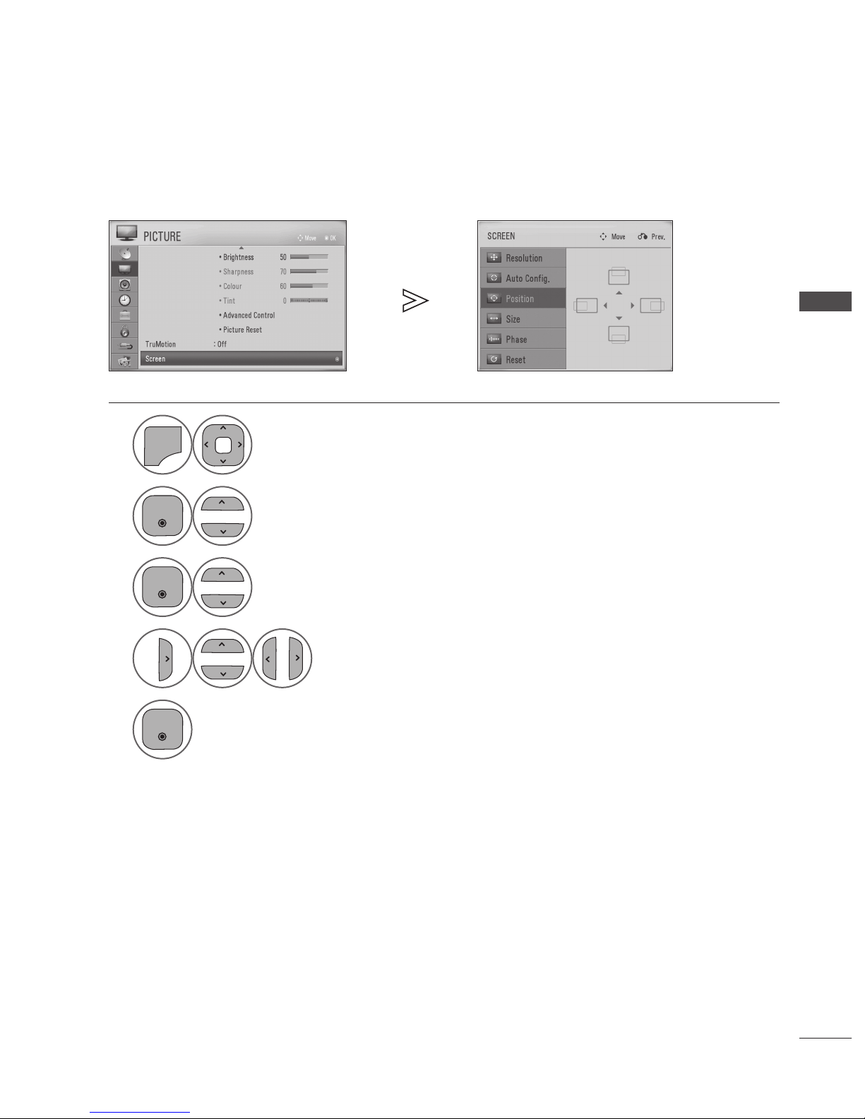
Adjustment for screen Position, Size, Phase
If the picture is not clear after auto adjustment and especially if characters are still trembling, adjust the picture phase manually.
1
P
A
G
E
P
1 2 3
4 506
7 8 9
LIST
Q.VIEW
INPUT
ENERGY
SAVING
MARK
FAV
MARK
FAV
RATIO
MUTE
AV MODE
MENU
GUIDE
Q.MENU
TV/
RAD
P
A
G
E
P
1 2 3
4 506
7 8 9
LIST
Q.VIEW
INPUT
ENERGY
SAVING
MARK
FAV
MARK
FAV
RATIO
MUTE
AV MODE
MENU
GUIDE
Q.MENU
TV/
RAD
Select PICTURE.
2
P
A
G
E
P
Q.VIEW
INPUT
ENERGY
SAVING
RATIO
MUTE
OK
AV MODE
Q.MENU
BACK
INFO
TV/
RAD
EXIT
P
A
G
E
P
Q.VIEW
INPUT
ENERGY
SAVING
RATIO
MUTE
AV MODE
Q.MENU
TV/
RAD
Select Screen.
3
P
A
G
E
P
Q.VIEW
INPUT
ENERGY
SAVING
RATIO
MUTE
OK
AV MODE
Q.MENU
BACK
INFO
TV/
RAD
EXIT
P
A
G
E
P
Q.VIEW
INPUT
ENERGY
SAVING
RATIO
MUTE
AV MODE
Q.MENU
TV/
RAD
Select Position, Size or Phase.
4
P
A
G
E
P
LIST
Q.VIEW
INPUT
ENERGY
SAVING
MARK
FAV
RATIO
MUTE
OK
AV MODE
GUIDE
Q.MENU
BACK
INFO
TV/
RAD
EXIT
P
A
G
E
P
Q.VIEW
INPUT
ENERGY
SAVING
RATIO
MUTE
AV MODE
Q.MENU
TV/
RAD
P
A
G
E
P
LIST
Q.VIEW
INPUT
ENERGY
SAVING
MARK
FAV
RATIO
MUTE
AV MODE
GUIDE
Q.MENU
TV/
RAD
Make appropriate adjustments.
5
P
A
G
E
P
Q.VIEW
INPUT
ENERGY
SAVING
RATIO
MUTE
OK
AV MODE
Q.MENU
BACK
INFO
TV/
RAD
EXIT
• Press the MENU/EXIT button to return to normal TV viewing.
• Press the BACK button to return to the previous screen.
 Loading...