How it Works
Log In / Sign Up
Buy Points
How it Works
FAQ
Contact Us
Questions and Suggestions
Users
LG
Loading...
#
42LC4R-ZA
42LC4T
42LC5
54
42LC50
42LC50C
6
42LC51
5
42LC51-ZA
3
42LC53
42LC53-ZA
42LC55
9
42LC5DC
9
42LC5 Series
7
42LC6DF
2
42LC6DF-UL
42LC7D
21
42LC7D - - 42"" LCD TV
42LC7D-AB
4
42LC7D Series
3
42LC7D-UB
2
42LC7DUK
3
42LC7D-ZA
42LC7R
15
42LC7RC
2
42LC7R Series
2
42LC7R-ZA
42LCD7D-AB
42LCSDC
2
42LCSOC
2
42LD320B
4
42LD320B-ZA
42LD320H
7
42LD320HUA
42LD340H
7
42LD340HUA
42LD343H
42LD345H
6
42LD4
3
42LD400
5
42LD4000
42LD400_LC420WUG-SCR7
42LD420
27
42LD420C
10
42LD420C-SA
42LD420N
2
42LD420-TA
42LD420-UA
2
42LD421
4
42LD426
42LD428
2
42LD450
32
42LD450C
7
42LD450CUA
42LD450N
4
42LD450N-ZA
42LD450-TA
42LD450UA
42LD450-ZA
42LD451C
42LD452B
5
42LD452B-UA
42LD452C
2
42LD455
3
42LD455B
42LD455H
42LD458
3
42LD458-ZA
42LD460
15
42LD460B
42LD460B/H
42LD460B/H-SA
42LD460-MA
42LD460-TA
42LD461C
5
42LD461C-TA
2
42LD461F
42LD462B
42LD462C
42LD465
10
42LD465C
42LD465-DA
3
42LD480-ZB
42LD490
2
42LD490-ZB
42LD4 Series
4
42LD5
42LD5000
42LD520
18
42LD520UA
42LD540
2
42LD550
39
42LD550N
2
42LD550N-ZC
42LD550-TA
42LD550UB
42LD550-ZC
42LD551
42LD551N-ZA
42LD551-ZA
42LD555-ZC
42LD5 Series
2
Loading...
Loading...
Nothing found
42LD450
Diagram
43 pgs
5.41 Mb
0
Owner Manual
36 pgs
5.58 Mb
0
Owner's Manual
220 pgs
13.17 Mb
0
Owner’s Manual
74 pgs
21.93 Mb
0
Owner’s Manual
100 pgs
34.63 Mb
0
Owner’s Manual
142 pgs
37.71 Mb
0
User Manual
142 pgs
5.78 Mb
0
Owner's Manual
172 pgs
71.67 Mb
0
Owner's Manual
142 pgs
6.34 Mb
0
Owner's Manual
142 pgs
38.09 Mb
0
Owner's Manual
142 pgs
6.34 Mb
0
Owner's Manual
217 pgs
18.88 Mb
0
Owner's Manual
100 pgs
4.39 Mb
0
Owner's Manual
100 pgs
33.69 Mb
0
Owner's Manual
74 pgs
21.44 Mb
0
Owner's Manual
212 pgs
69.63 Mb
0
Owner’s Manual
242 pgs
48.61 Mb
0
Service Manual
41 pgs
6.31 Mb
0
Specifications
2 pgs
1.75 Mb
0
Owner’s Manual [ar]
206 pgs
16.64 Mb
0
Owner's Manual [es]
160 pgs
72.42 Mb
0
User Manual [es]
206 pgs
12.94 Mb
0
User Manual [fr]
206 pgs
13.32 Mb
0
User manual [hr]
206 pgs
13.27 Mb
0
User Manual [hu]
206 pgs
13.39 Mb
0
User Manual [it]
206 pgs
13.28 Mb
0
User Manual [it]
206 pgs
13.57 Mb
0
User Manual [no]
206 pgs
13.49 Mb
0
OPERATING INSTRUCTIONS [pl]
206 pgs
13.82 Mb
0
User Manual [pl]
206 pgs
13.52 Mb
0
User Manual [ru]
206 pgs
13.59 Mb
0
User Manual [uk]
206 pgs
13.35 Mb
0
Table of contents
Loading...
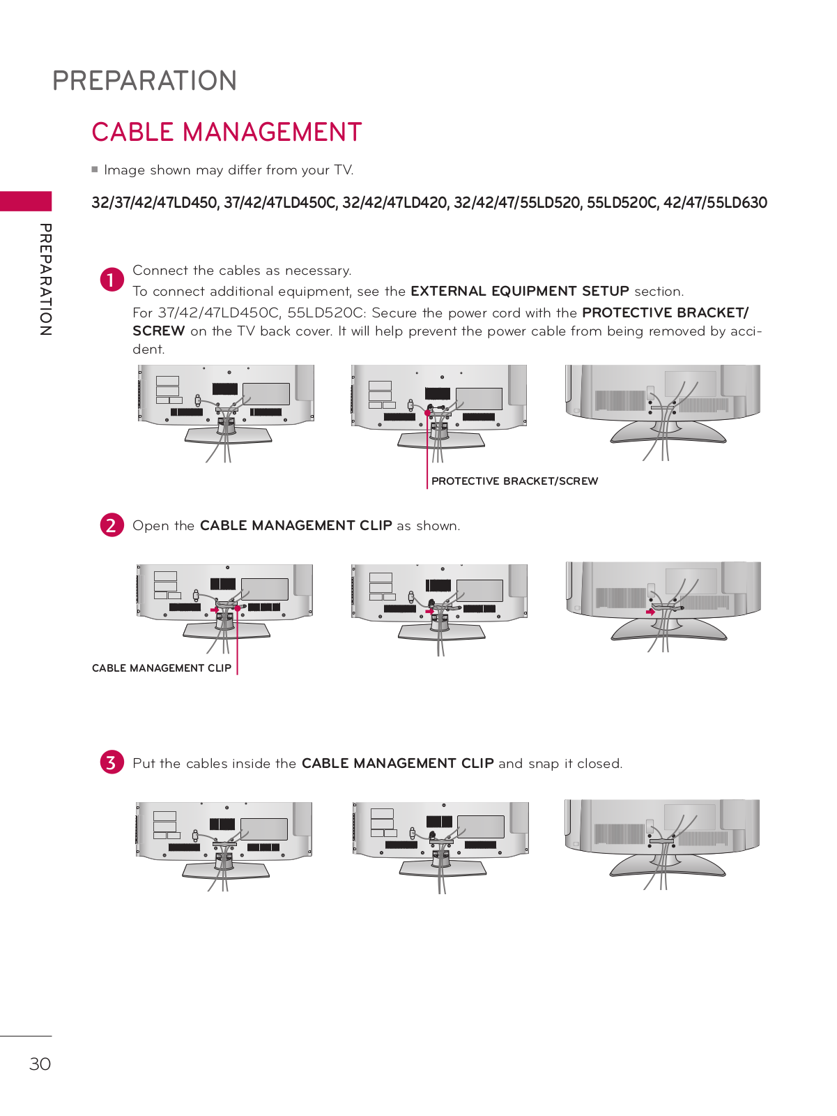
LG 42LD450 Owner's Manual
...
LG Owner's Manual
Download
Specifications and Main Features
Frequently Asked Questions
User Manual
Download
Loading...
+
142
hidden pages
Unhide
You need points to download manuals.
1 point = 1 manual.
You can buy points or you can get point for every manual you upload.
Buy points
Upload your manuals
 Loading...