

Page 1
42
42 Inch(Wide)
42 42
Inch(Wide) PDP SVC Training Manual
Inch(Wide)Inch(Wide)
PDP SVC Training Manual
PDP SVC Training Manual PDP SVC Training Manual
LG Electronics / DND QA
Page 2
Contents
Contents
ContentsContents
Ⅰ
Ⅰ. Usage/Service Points to be concerned
ⅠⅠ
Ⅱ
Ⅱ. Module formation & spec
ⅡⅡ
Ⅲ
Ⅲ. Screen defect diagnosis
ⅢⅢ
1. 4/7 or 3/7 of screen is not displayed.
2. Screen by Data COF is not displayed.
3. one or more of Data COF IC have regular vertical lines.
4. Data COF IC unit error pattern
5. The screen by Scan COF is not displayed.
6. Regular- interval vertical line in the whole screen.
7. Vertical data copy
8. One or more vertical bars.
9. One or more horizontal bars.
10. Input signal pattern is displayed but the whole brightness of screen is dark.
11. In full white pattern, foreign color is displayed or in full black pattern, misdischarge is partially occurred..
12. In full white pattern, the brightness is getting darker toward the center.
13. A specific brightness of one color is not clear.
Ⅳ
Ⅳ. Non-picture defect diag nosis
ⅣⅣ
!
!. One Point Service Guide(42 Inch, 40 Inch)
!!
Page 3
Ⅰ
Ⅰ.
. Usage/Service points to be concerned
ⅠⅠ
Usage/Service points to be concerned
. .
Usage/Service points to be concernedUsage/Service points to be concerned
Color PDP is a display device consisting of Panel section & Drive section. Panel section is composed of electrode,
fluorescent substances ,dielectrics and gases, and drive section is a combination of electrical circuit section and
PCB section. We call this concrete as PDP Module Ass’y and the following shows warning.
SUGGGESTIONS
1. Static precaution
Drive section circuit is C-MOS circuit, so to protect against static electricity, wear static-proof wrist band.
2. Cleaning
when wiping panel, do not use liquid cleaner or other chemicals . Use a damp cloth for cleaning .
3. handling
Color PDP uses high voltage(Max.500V). Be aware of electronic shock when handling PDP Unit and don’t touch drive circuit.
and even driver circuit’s capacitor is turned off but charge still remains there, so to touch drive circuit, be sure to wait at least 1 minute.
4. Warning when connecting signal & Power Connector in operation
do not touch connector while Color PDP is operating.
5. PDP servicing and guarantee
Glass Panel and Drive Circuit section are linked and operating together.
if you disassemble and assemble the product in your own hands , LGE is exempted from the guarantee of function, quality and etc.
6. Damage in still image
Color PDP uses fluorescent material. The quality of PDP fluorescence by nature becomes deteriorated if using it in the same condition of CRT.
To prevent this symptom, input full-screen regularly or use screensaver software.
So do not display the still image for a long time.
7. Temperature & ventilation
Color PDP’s Glass Panel section and Drive circuit section emit the heat so the temperature shall be kept under 40.
the temperature of glass panel section is pretty high because built-in drive circuit emits the heat.
PDP is operating with high voltage therefore be sure to keep it away from conductive objects.
8. Warning when handling Module
be aware that PDP shall not be touched by metal or hard objects and shocked by the heat or mechanical force.
be careful when disassembling or handling.
be sure to wear glove for preventing injury when the glass’s broken.
LG Electronics/DND QA
LG Electronics/DND QA Gr
LG Electronics/DND QA LG Electronics/DND QA
Gr
GrGr
Page 4
Service warning
1. When inserting parts or PCB, fasten the lead line to terminal before soldering.
2. When inserting high- voltage resistance(metal oxide film resistance or metal film resistance), keep 10mm away from PCB
3. High-voltage or high-temperature parts shall be away from the lead line.
4. This chassis is insulation(cold) chassis but for safety, it is better to use insulation trance.
when servicing power board, be sure to use insulation trance.
5. While PDP Module is in operati o n, d o not co nn ect or remov e li n es.
"
" With COF or panel defect, report it to LGE PDP module service department.
""
Defect diagnosis tool
1. One DVM ( FLUKE 87 or similar type )
2. Digital Oscilloscope ( over 200MHZ )
LG Electronics/DND QA
LG Electronics/DND QA Gr
LG Electronics/DND QA LG Electronics/DND QA
Gr
GrGr
Page 5
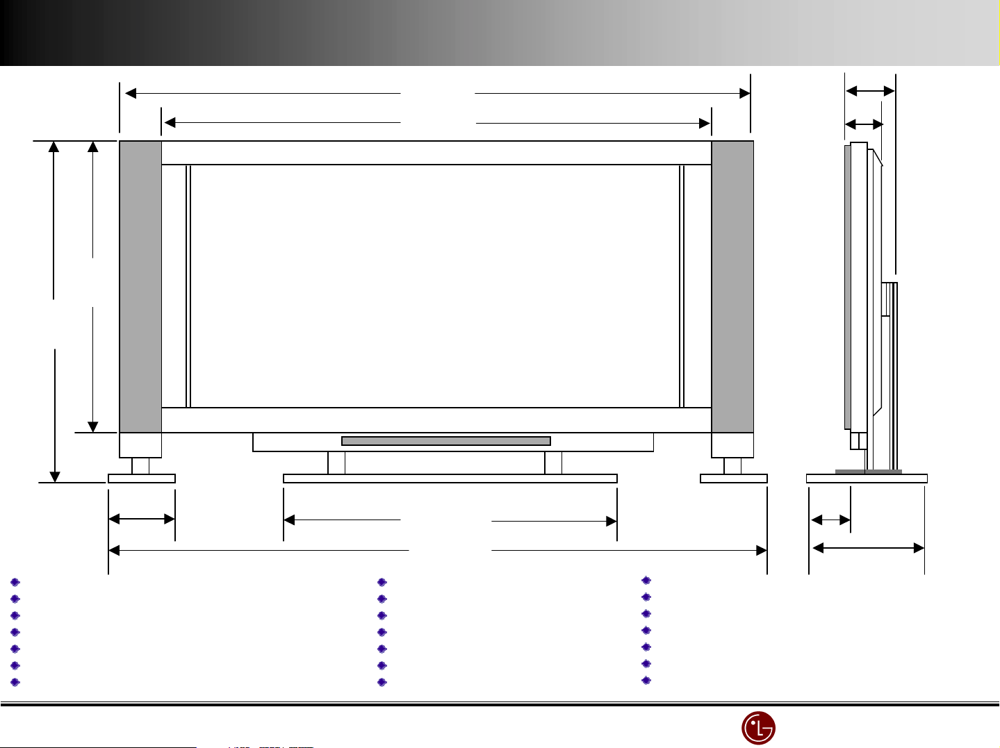
693.5
693.5
693.5693.5
635
635
635635
#259
#259
#259#259
#056
#056
#056#056
Power : 220V 60Hz
Power : 220V 60Hz
Power : 220V 60HzPower : 220V 60Hz
Power consumption : 340W
Power consumption : 340W
Power consumption : 340WPower consumption : 340W
MN
MN----42PZ10 Spec & Features
MNMN
42PZ10 Spec & Features
42PZ10 Spec & Features42PZ10 Spec & Features
9#.5
9#.5
9#.59#.5
82
82
8282
220
220
220220
aspect ratio: #6:9
aspect ratio: #6:9
aspect ratio: #6:9 aspect ratio: #6:9
screen size (H X V) : 920.# X 5#8.4mm
screen size (H X V) : 920.# X 5#8.4mm
screen size (H X V) : 920.# X 5#8.4mmscreen size (H X V) : 920.# X 5#8.4mm
resolution : 852 X 480 (VGA)
resolution : 852 X 480 (VGA)
resolution : 852 X 480 (VGA)resolution : 852 X 480 (VGA)
Cell Pitch (H X V) : 0.36 X #.08
Cell Pitch (H X V) : 0.36 X #.08
Cell Pitch (H X V) : 0.36 X #.08Cell Pitch (H X V) : 0.36 X #.08
displayable colors (R,G,B) : #,677K (256 X 256 X 256)
displayable colors (R,G,B) : #,677K (256 X 256 X 256)
displayable colors (R,G,B) : #,677K (256 X 256 X 256)displayable colors (R,G,B) : #,677K (256 X 256 X 256)
brightness : 250
brightness : 250 cd
brightness : 250 brightness : 250
contrast ratio : 250:# (w/o filter ; 700:# )
contrast ratio : 250:# (w/o filter ; 700:# )
contrast ratio : 250:# (w/o filter ; 700:# )contrast ratio : 250:# (w/o filter ; 700:# )
cd////$$$$ (w/o filter : 550
(w/o filter : 550 cd
cdcd
(w/o filter : 550 (w/o filter : 550
cd////$$$$ ))))
cdcd
779.5
779.5
779.5779.5
#379
#379
#379#379
color temperature : over 8500
color temperature : over 8500%%%% K
color temperature : over 8500color temperature : over 8500
viewing angle : over #60
viewing angle : over #60%%%%
viewing angle : over #60viewing angle : over #60
input signal : NTSC, HD, VGA ,SVGA
input signal : NTSC, HD, VGA ,SVGA
input signal : NTSC, HD, VGA ,SVGAinput signal : NTSC, HD, VGA ,SVGA
Twin Picture : PC/AV
Twin Picture : PC/AV
Twin Picture : PC/AVTwin Picture : PC/AV
PC input : D
PC input : D----SUB #5
PC input : DPC input : D
Control : D
Control : D----SUB25 / STB connection
Control : DControl : D
Video input : CVBS
Video input : CVBS
Video input : CVBSVideo input : CVBS
SUB #5
SUB #5SUB #5
SUB25 / STB connection
SUB25 / STB connectionSUB25 / STB connection
K
K K
##4.8
##4.8
##4.8##4.8
28#
28#
28#28#
SSSS----Video input
Video input
Video inputVideo input
DVD input(Y,
DVD input(Y,Cb
DVD input(Y,DVD input(Y,
Audio input : R/L
Audio input : R/L
Audio input : R/LAudio input : R/L
Power Cable : 3
Power Cable : 3&&&& ((((Ground terminal)
Power Cable : 3Power Cable : 3
Sound Output (Speaker) : R.L Out
Sound Output (Speaker) : R.L Out
Sound Output (Speaker) : R.L OutSound Output (Speaker) : R.L Out
R,G,B input : D
R,G,B input : D----SUB25 (RGBHV) : STB connection
R,G,B input : DR,G,B input : D
AC Input : 220V 60Hz
AC Input : 220V 60Hz
AC Input : 220V 60HzAC Input : 220V 60Hz
Cb,Cr)/R,L : Y/Y.
,Cr)/R,L : Y/Y. Pb
CbCb
,Cr)/R,L : Y/Y. ,Cr)/R,L : Y/Y.
Ground terminal)
Ground terminal)Ground terminal)
SUB25 (RGBHV) : STB connection
SUB25 (RGBHV) : STB connectionSUB25 (RGBHV) : STB connection
LG Electronics/DND QA
LG Electronics/DND QA Gr
LG Electronics/DND QA LG Electronics/DND QA
Pb////Cb
Cb, Pr/Cr+R/L
PbPb
, Pr/Cr+R/L
CbCb
, Pr/Cr+R/L, Pr/Cr+R/L
Gr
GrGr
Page 6
Spec of Models
Spec of Models
Spec of ModelsSpec of Models
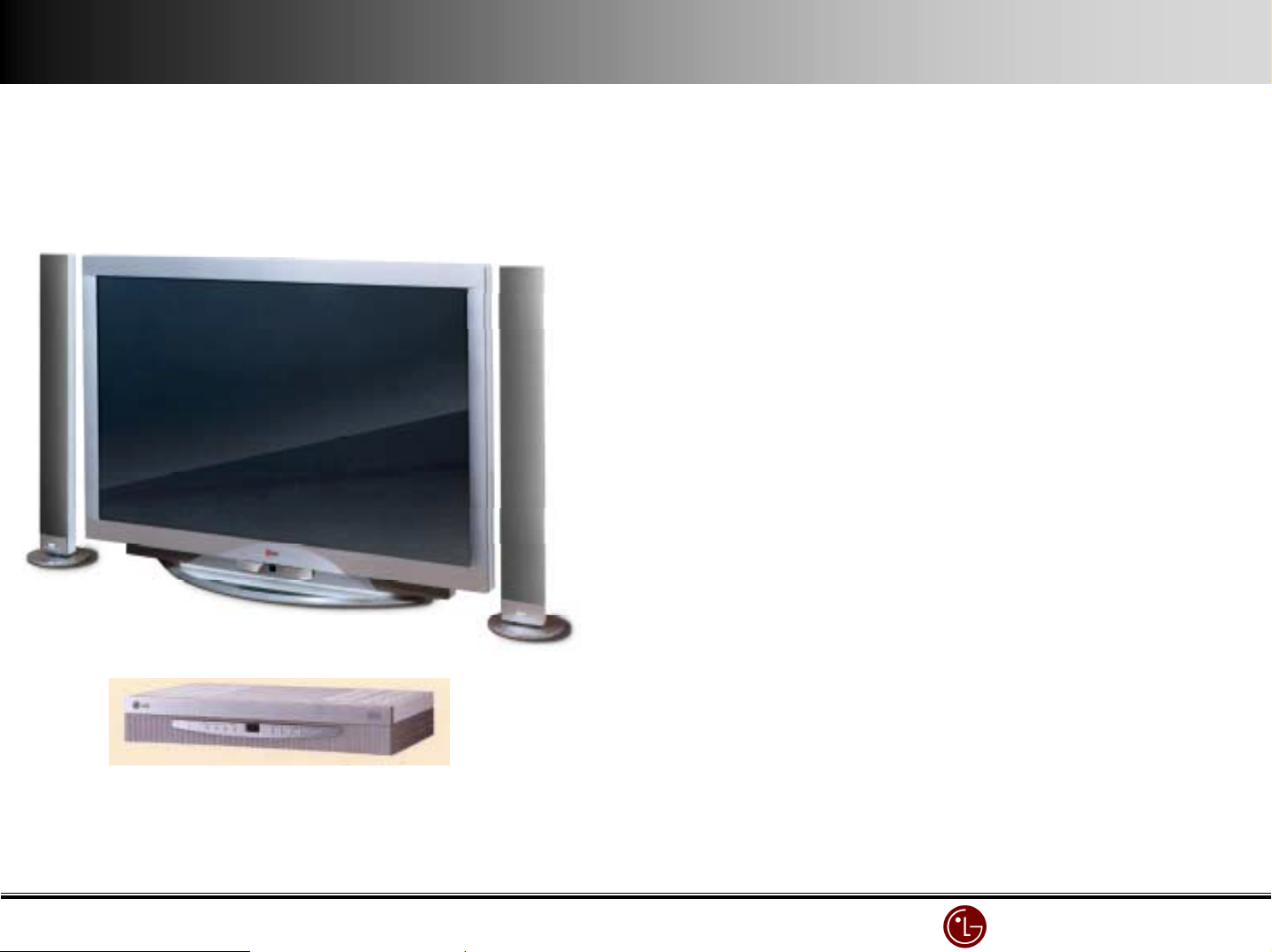
MN-42PZ10(42”W PDP MNT)
Market : Korea / N_ America / S_America
Market : Korea / N_ America / S_America
Market : Korea / N_ America / S_AmericaMarket : Korea / N_ America / S_America
(200#. July ~)
(200#. July ~)
(200#. July ~)(200#. July ~)
((((Example of Desk Top Type)
Example of Desk Top Type)
Example of Desk Top Type)Example of Desk Top Type)
RN
RN----BA##(3 System Multi STB)
BA##(3 System Multi STB)
RNRN
BA##(3 System Multi STB)BA##(3 System Multi STB)
430(W)X78(H)X280mm(D)
ITEMS SPECIFICATIONS(Tentative)
Screen Size: 42 inch/ 106cm diagonal
Aspect Ratio: 16 :9 (width:height)
Resolution: 852 x 480 Pixels(SD grade)
Peak Brightness : typ.240cd/m² (with filter 60%)
Contrast Ratio: 700:1(Dark Room & with filter 45%)
Viewing Angle: 160° horizontally and vertically
Displayable Colors: 16.7 million
Weight: kg (MNT), kg(D/stand), kg(spk.)x2
Life: >25,000 hours
(elapsed time to 50% of initial brightness)
Dimensions(MNT) : 105.6cm wide, 63.4cm high, 8.2cm deep
Input Terminals : RF terminal(PAL/SECAM/NTSC)
(Set Top Box) Composite Video input(RCA) X 2, S-Video
Audio L&R input(RCA) X 2
Component Video (Y,Pb,Pr) + R/L for DVD
Component Video (Y,Pb,Pr)+ R/L for HDTV Stb.
RGB-SUB 15 pin for HDTV Stb.(480p/720p/1080i)
Analog RGB-SUB 15pin(PC VGA ~SVGA)
Stereo Input for PC Audio
Output Terminals : Analog RGB-SUB 15 pin(PC/DTV input bypass)
(Set Top Box) Audio L&R(RCA)
RGB-SUB 25 Pin for MNT(RGB/HV in & Control)
Composite Video output + R/L output
Input Terminals : Analog RGB-SUB 15 pin (Compatible with PC
(MNT) VGA ~SVGA, Compressed XGA)
RGB-SUB 25 Pin for STB(RGB/HV in & Control)
Component Video (Y,Pb,Pr) for DVD & DTV Stb.
Composite Video input(PAL/SECAM/NTSC)
Audio L&R input(RCA)X2
Display Frequency : 15.73kHz to 60kHz horizontally, 50Hz to 75Hz(V)
Picture : PIP(2Tuner:STB), Twin Picture, Digital Comb filter,
Digital Video Enhancer(Jagging free )
Sound : A2 stereo, AVL, Dolby Virtual, 2x10Wrms
Remote Control : Included(Unified)
External Control : D-sub 25-pin connector
Power Source : 110-240V , 50/60 Hz
Power Consumption: 300 watts( with Max. Audio : 320W)
LG Electronics/DND QA
LG Electronics/DND QA Gr
LG Electronics/DND QA LG Electronics/DND QA
Gr
GrGr
Page 7
SET TOP BOX
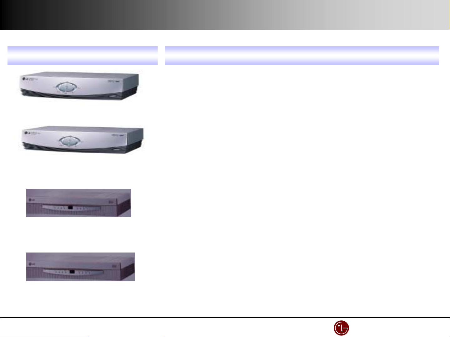
SET TOP BOX Compatible Model
SET TOP BOX SET TOP BOX
DIGITAL SET TOP BOX ( SK
DIGITAL SET TOP BOX ( SK----0#0T )
DIGITAL SET TOP BOX ( SKDIGITAL SET TOP BOX ( SK
DIGITAL SET TOP BOX ( SK
DIGITAL SET TOP BOX ( SK----0##T )
DIGITAL SET TOP BOX ( SKDIGITAL SET TOP BOX ( SK
0#0T )
0#0T )0#0T )
0##T )
0##T )0##T )
PDP STB type & compatible model
PDP STB type & compatible model
PDP STB type & compatible modelPDP STB type & compatible model
Compatible Model
Compatible Model Compatible Model
MN
MN----40X3M , MN
40X3M , MN----40PA#0, MN
MNMN
40X3M , MN40X3M , MN
all Model can be connected but because of noise problem with int
all Model can be connected but because of noise problem with internal
all Model can be connected but because of noise problem with intall Model can be connected but because of noise problem with int
fan, it is terminated.Be sure that MN
fan, it is terminated.Be sure that MN----40X3M is not compatible with SK
fan, it is terminated.Be sure that MNfan, it is terminated.Be sure that MN
Separately : dedicated cable (AP
Separately : dedicated cable (AP----EA#0)
Separately : dedicated cable (APSeparately : dedicated cable (AP
MN
MN----40PA#0, MN
40PA#0, MN----40PA#0A, MN
MNMN
40PA#0, MN40PA#0, MN
All but MN
All but MN----40X3M can be used
All but MNAll but MN
separately : dedicated cable (AP
separately : dedicated cable (AP----EA#0)
separately : dedicated cable (APseparately : dedicated cable (AP
40X3M can be used
40X3M can be used40X3M can be used
40PA#0, MN----40PA#0A, MN
40PA#0, MN40PA#0, MN
40PA#0A, MN----42PZ#0, MN
40PA#0A, MN40PA#0A, MN
40PA#0A, MN----42PZ#0, MN
40PA#0A, MN40PA#0A, MN
40X3M is not compatible with SK----0##T
40X3M is not compatible with SK40X3M is not compatible with SK
EA#0)
EA#0)EA#0)
42PZ#0, MN----60PZ#0
42PZ#0, MN42PZ#0, MN
EA#0)
EA#0)EA#0)
42PZ#0, MN----60PZ#0
42PZ#0, MN42PZ#0, MN
60PZ#0
60PZ#060PZ#0
60PZ#0
60PZ#060PZ#0
ernal
ernalernal
0##T
0##T 0##T
ANALOG SET TOP BOX ( RN
ANALOG SET TOP BOX ( RN----BA#0 )
ANALOG SET TOP BOX ( RNANALOG SET TOP BOX ( RN
ANALOG SET TOP BOX ( RN
ANALOG SET TOP BOX ( RN----BA## )
ANALOG SET TOP BOX ( RNANALOG SET TOP BOX ( RN
BA#0 )
BA#0 )BA#0 )
BA## )
BA## )BA## )
MN
MN----40PA#0, MN
40PA#0, MN----40PA#0A only
MNMN
40PA#0, MN40PA#0, MN
Only related model can be used.
Only related model can be used.
Only related model can be used.Only related model can be used.
MN
MN----42PZ#0 only
42PZ#0 only
MNMN
42PZ#0 only42PZ#0 only
Only related model can be used
Only related model can be used
Only related model can be usedOnly related model can be used
40PA#0A only
40PA#0A only40PA#0A only
LG Electronics/DND QA
LG Electronics/DND QA Gr
LG Electronics/DND QA LG Electronics/DND QA
Gr
GrGr
Page 8
Ⅱ
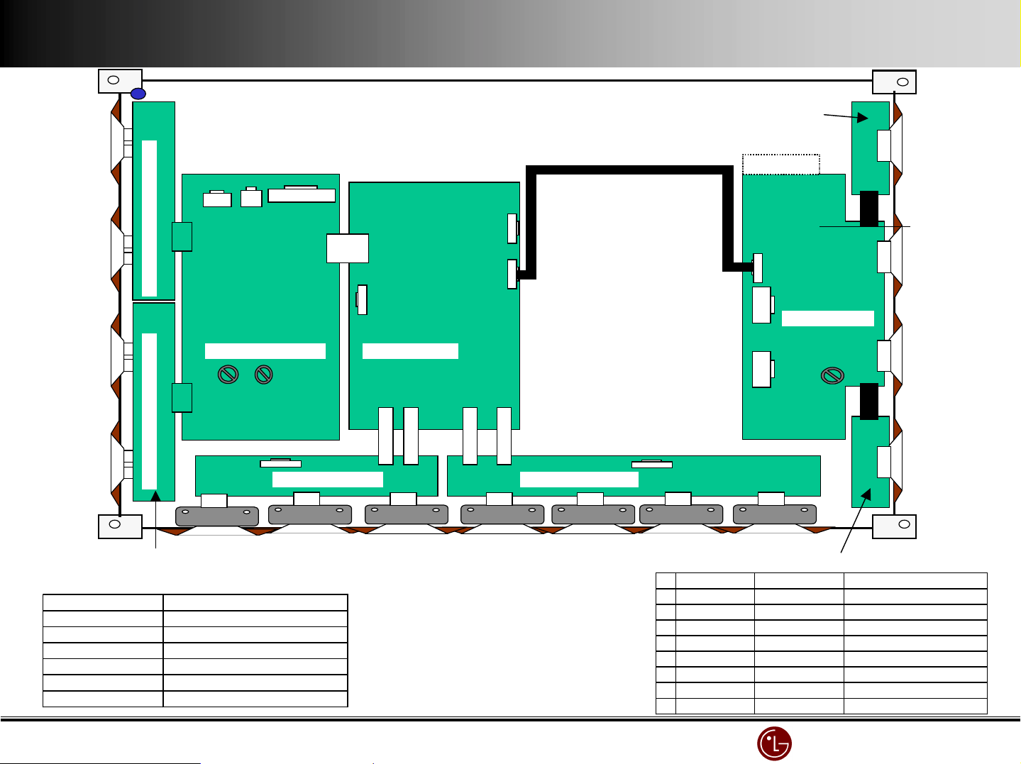
Ⅱ.... Module diagram & spec
ⅡⅡ
Module diagram & spec
Module diagram & specModule diagram & spec
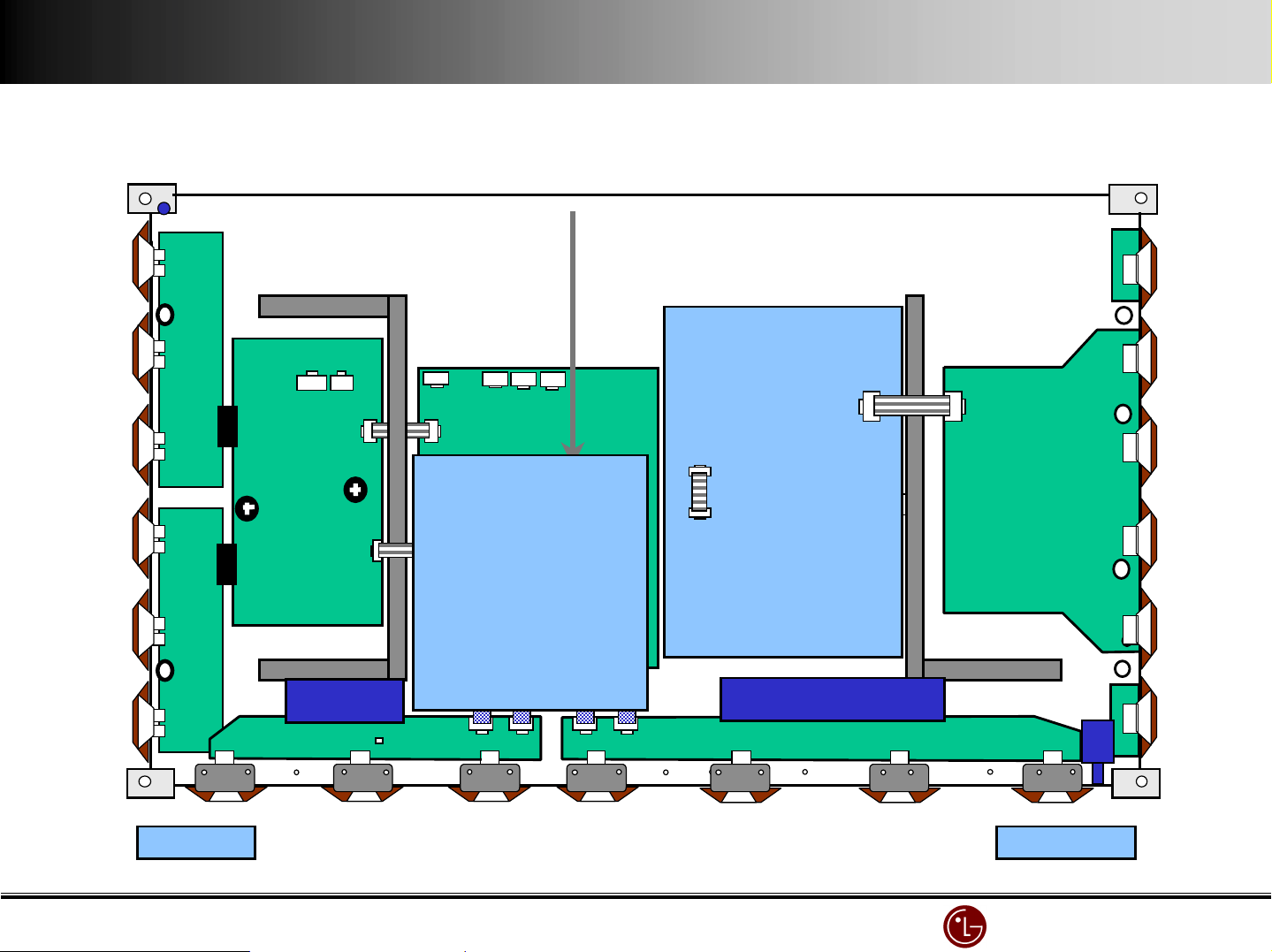
P3 P2
P5
P4
ZCNT TOP B/D ASSY
Label
P300
Y DRV Upper B/D ASSYY DRV Lower B/D ASSY
Y SUS B/D ASSY CTRL B/D ASSY
VR2 VR1
P6
P1
X LEFT B/D ASS’Y
YDRV B/D ASSY
5XT5 R )'4(C 'B45(CO))5CTIO)
5XT5 R )'4(C 'B45(CO))5CTIO)
5XT5 R )'4(C 'B45(CO))5CTIO)5XT5R)'4(C 'B45(CO))5CTIO)
,+../,-+* 0upp7y(08g.a7
P1~P2[X(B23] 5V,(15V,(V'
P3[Y(SUS(B23] VSC,(VS5TUP
P2[Y(SUS(B23] 5V,(15V,(VS
P1[Z(SUS(B23] 5V,(15V,(VS
P300[CTR4(B23] 5V
P100[CTR4(B23] ((((((((((((VI35O(SI6)'4
P100
X RIGHT B/D ASSY
ZSUS B/D ASSY
P1
P2
P2
ZCNT BOTTOM B/D ASSY
P'RT()O. p*+du,-(.am/0-a.da*d
1 6871QTH003B PWB(PCB)('SSY ZC)T(TOP(B23('SSY
26871QZH002B PWB(PCB)('SSY ZSUS(B23('SSY(
36871QTH004B PWB(PCB)('SSY ZC)T(BOTTOM(B23('SSY(
46871Q4H012' PWB(PCB)('SSY X(45FT(BOTTOM(B23('SSY
56871QRH010' PWB(PCB)('SSY X(RI6HT(BOTTOM(B23('SSY
66871Q3P016B PWB(PCB)('SSY Y3RV(Upp/*(B23('SSY(
76871Q3P017B PWB(PCB)('SSY Y3RV(4+w/*(B23('SSY(
86871QYH015' PWB(PCB)('SSY YSUS(B23('SSY(
VR1
LG Electronics/DND QA
LG Electronics/DND QA Gr
LG Electronics/DND QA LG Electronics/DND QA
Gr
GrGr
Page 9
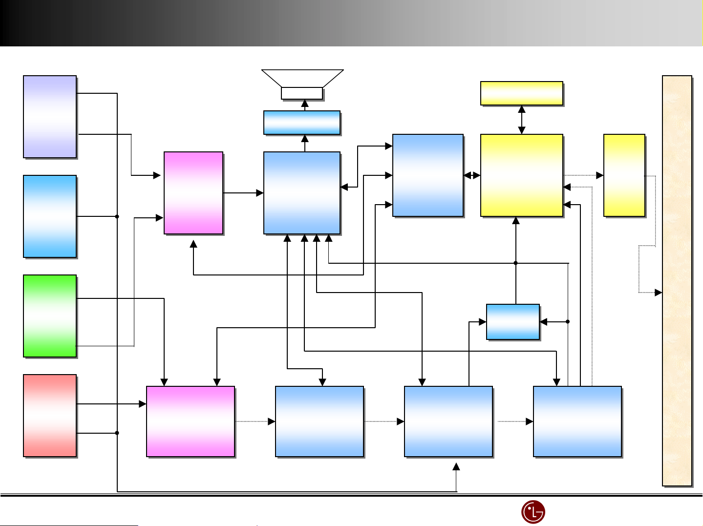
YY
Y-
Y
--
- Drive
DriveDrive
Drive
YY
Y-
Y
--
- Drive
DriveDrive
Drive
YYYY----Board
Board
BoardBoard
X
X – Board ( L )
X X
Controller
Controller
ControllerController
Board ( L )
Board ( L )Board ( L )
Board
Board
BoardBoard
VSC
VSC
VSCVSC
Board
Board
BoardBoard
POWER
POWER
POWERPOWER
Board
Board
BoardBoard
CN#
CN#
CN#C N#
CN2
CN2
CN2C N2
EMI Filter
EMI Filter
EMI FilterEMI Filter
X
X – Board ( R )
Board ( R )
X X
Board ( R )Board ( R )
ZZZZ----Board
Board
BoardBoard
Local key
Local key
Local keyLocal key
Main Power
Main Power
Main PowerMain Power
LG Electronics/DND QA
LG Electronics/DND QA Gr
LG Electronics/DND QA LG Electronics/DND QA
Gr
GrGr
Page 10
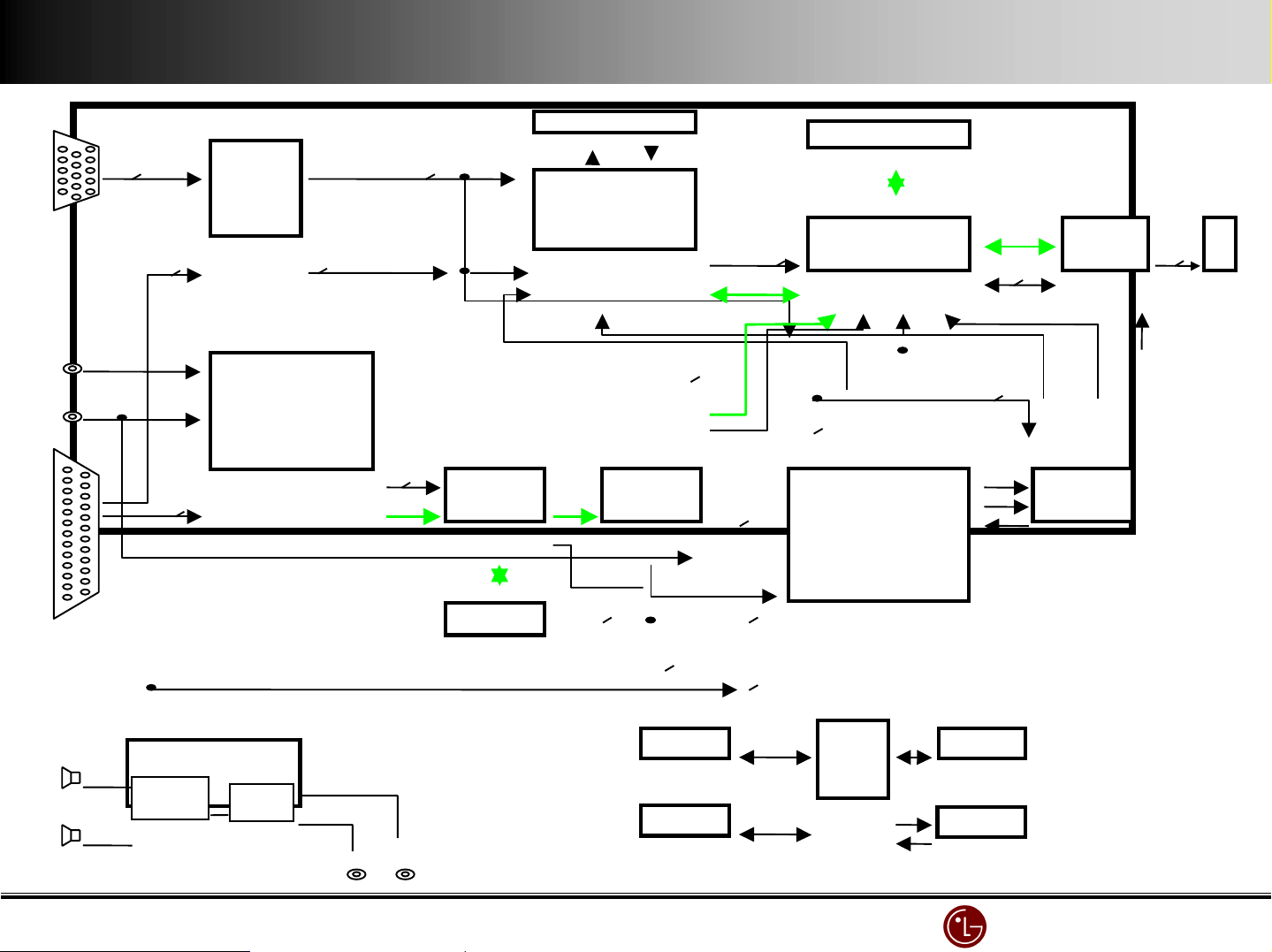
STB
STB
STBSTB
STB
STB
STBSTB
PC
PC
PCPC
PC
PC
PCPC
LA7222
LA7222
LA7222LA7222
LA7222
LA7222
LA7222LA7222
LA4282
LA4282
LA4282LA4282
LA4282
LA4282
LA4282LA4282
CXA2022S
CXA2022S
CXA2022SCXA2022S
CXA2022S
CXA2022S
CXA2022SCXA2022S
MICOM
MICOM
MICOMMICOM
CXP7500#0
CXP7500#0
CXP7500#0CXP7500#0
Monitor Block diagram
Monitor Block diagram
Monitor Block diagramMonitor Block diagram
2222MMMM----SDRAM
SDRAM
SDRAMSDRAM
2222MMMM----SDRAM
SDRAM
SDRAMSDRAM
Buffer
Buffer
BufferBuffer
Buffer
Buffer
MX88L284
MX88L284
MX88L284MX88L284
MX88L284
MX88L284
MX88L284MX88L284
BufferBuffer
HC54#
HC54#
HC54#HC54#
HC54#
HC54#
HC54#HC54#
PDP MPDULEPDP MPDULE
PDP MPDULE
PDP MPDULE
Video
Video
VideoVideo
Video
Video
VideoVideo
DVD
DVD
DVDDVD
DVD
DVD
DVDDVD
VPC3230
VPC3230
VPC3230VPC3230
VPC3230
VPC3230
VPC3230VPC3230
SDA94#0
SDA94#0
SDA94#0SDA94#0
SDA94#0
SDA94#0
SDA94#0SDA94#0
CXA2#0#
CXA2#0#
CXA2#0#CXA2#0#
CXA2#0#
CXA2#0#
CXA2#0#CXA2#0#
HC74
HC74
HC74HC74
HC74
HC74
HC74HC74
THS8083
THS8083
THS8083THS8083
THS8083
THS8083
THS8083THS8083
LG Electronics/DND QA
LG Electronics/DND QA Gr
LG Electronics/DND QA LG Electronics/DND QA
Gr
GrGr
Page 11
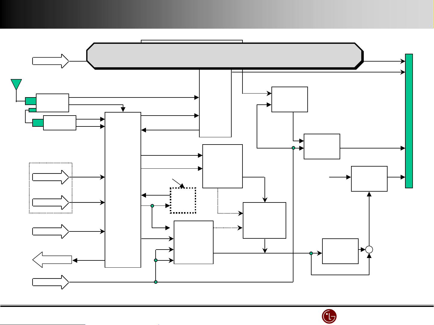
MN-42PZ10 VSC(JAG200 & FLI2200) Block Diagram
CVBS
YCbCr/
YPbPr
RGBHV
5
RGBHV
5
YUV
2
VIDEO
SWITCH
(M52758FP)
COLOR DECODER
(VPC3230D)
3
H/V
SOG
H/V/
FIELD/
LLC1
4
3RGB
DEINTERLACE
(FLI2200)
MEMORY
(4M-BYTE)
MONOSTALE MULTIBIB.
SOG_OUT
A/D CONVERTER
(CXA3516R)
H
ENHANCER
(FLI2220)
2H/V
CLAMP_AD
3RGB
5
H/V/CLK/
HBLK/VBLK
5Y,U,V,H,V
MEMORY (6M-B YTE )
2PLLH/CLK
5
RGBHV
COLOR CONTROL
SCALER
(JAG200)
&
VIDEO SWITCH
(CXA2101Q)
Buffer
(74F574 x 4)
4
H/V/DE/CLK
V
H
2H/V
H
V
Clamp
(GEN. CLAMP)
DISP_EN
EPLD
41P
8
R
AUDIO AMP
LA4282(L&R)
L
AUDIO
Sound
Processor
(MSP3401G)
3Y,Pb,Pr(MNT)
Y,Pb,Pr(STB)
(74HCT373)
ROM
(AT29C010)
3
PORT EXP
MICOM
(M62320X3)
EEPROM
X2416P
LG Electronics/DND QA
LG Electronics/DND QA Gr
LG Electronics/DND QA LG Electronics/DND QA
Gr
GrGr
Page 12
PC
TUNER.1
TUNER.2
TV (M)
L/R(tv)
TV (S)
RN-BA11(Tuner Receiver) Block - Diagram
RN-BA11(Tuner Receiver) Block - Diagram
L / R
2’nd SiF
L/R
L/R(tv)
MSP3401G
Sound
Processor
RGB(PC)
M52758FP
RGB/YUV
S/W
RGB (DTV)
Ro
Lo
S-VHS
==== AUDIO >?
9:;<
9:;<1
9:;<9:;<
9:;<
9:;<2
9:;<9:;<
>?
>?>?
MNT_OUT
DVD/DTV
(RCA JACK)
Y / C
V, L/R
V, L/R
CXA2069Q
A/V SW
CVBS
Y/C
OPTION
Y/C
CVBS
Y/C
DVD_Y
Y,Cr,Cb (DVD)
DCF
VPC3230D
(MAIN)
Vido
Proessor
VPC3230D
(SUB)
Video
Proessor
WE
RE
Y,Pb,Pr(DTV)
Y,Pb,Pr(DTV)
MS81V04160
FRAME
MEMORY
M52756FP
RGB/YUV
S/W
RGB(OSD)
LGTV1001
DRP
CXA2119M
S/W
+
RGB
YUV
LG Electronics/DND QA
LG Electronics/DND QA Gr
LG Electronics/DND QA LG Electronics/DND QA
Gr
GrGr
Page 13
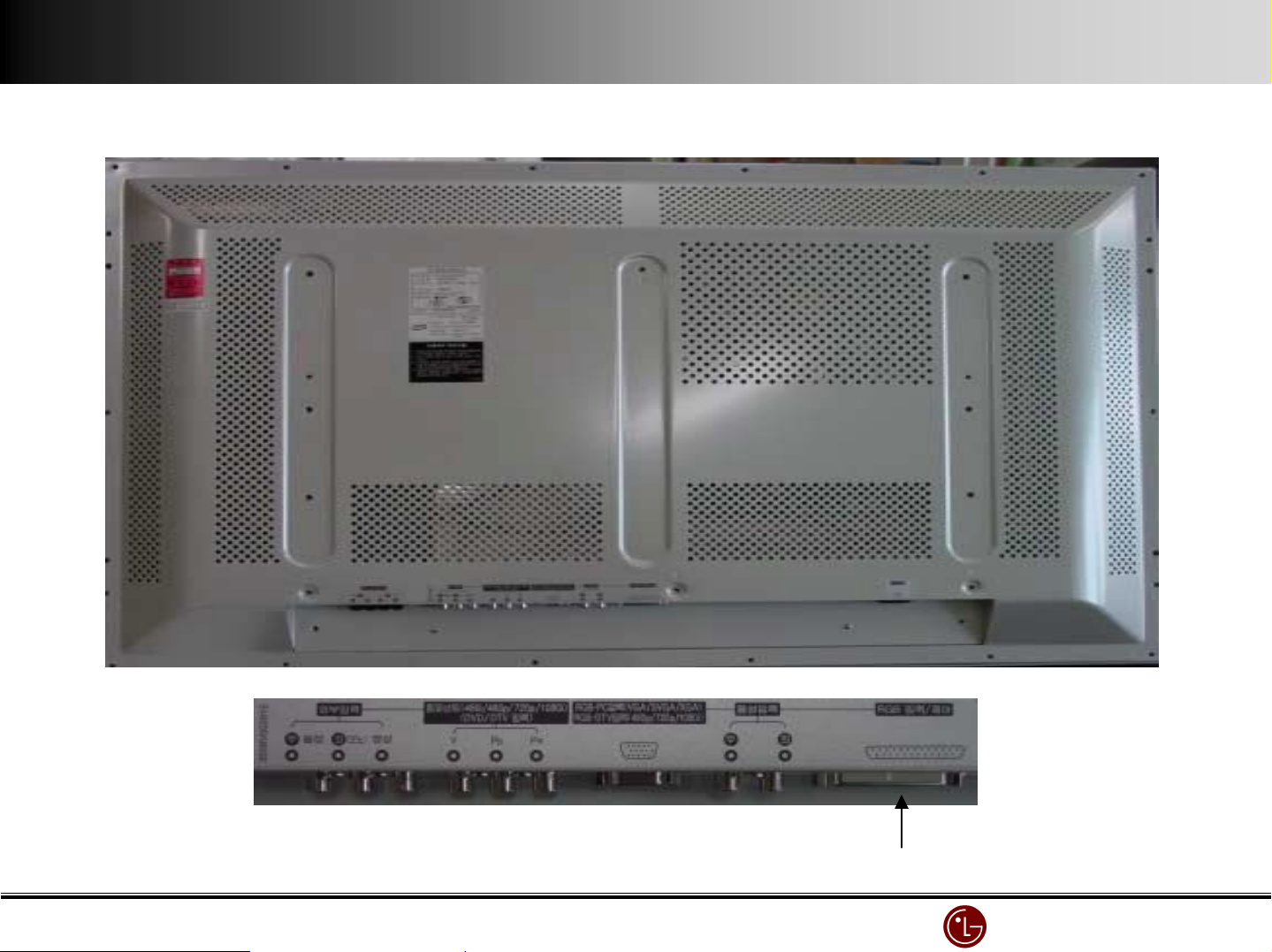
Product back & monitor in/output section
Product back & monitor in/output section
Product back & monitor in/output sectionProduct back & monitor in/output section
Connecting 25 Pin cable
Connecting 25 Pin cable
Connecting 25 Pin cableConnecting 25 Pin cable
(when connecting 25 Pin cable,
(when connecting 25 Pin cable,
(when connecting 25 Pin cable,(when connecting 25 Pin cable,
Connect external equipment to STB)
Connect external equipment to STB)
Connect external equipment to STB)Connect external equipment to STB)
LG Electronics/DND QA
LG Electronics/DND QA Gr
LG Electronics/DND QA LG Electronics/DND QA
Gr
GrGr
Page 14
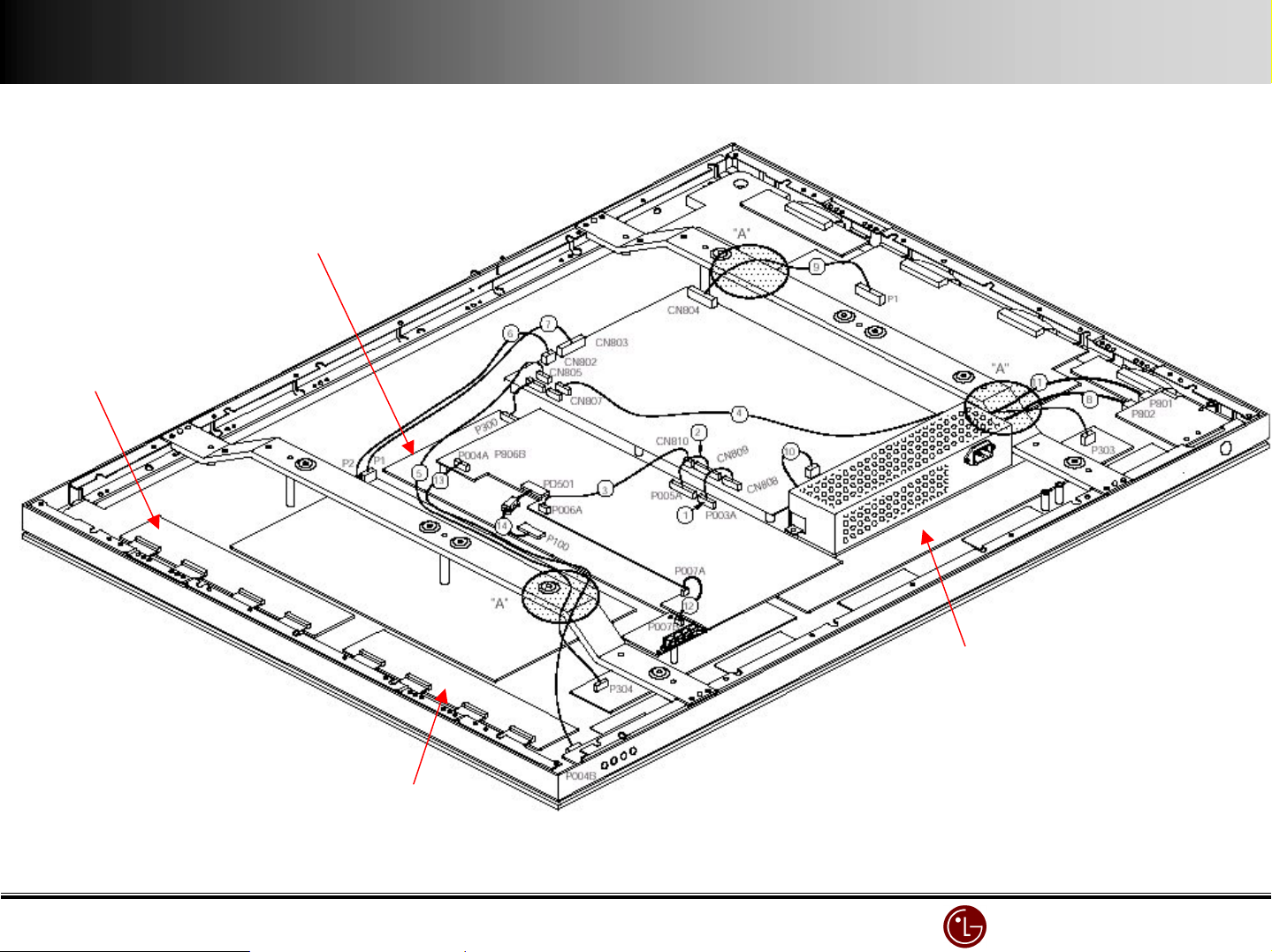
YYYY----Drive (TOP)
Drive (TOP)
Drive (TOP)Drive (TOP)
Controller Board
Controller Board
Controller BoardController Board
Connection diagram (back cover
Connection diagram (back cover’s open)
Connection diagram (back coverConnection diagram (back cover
ZZZZ----Board
Board
BoardBoard
Power Board
Power Board
Power BoardPower Board
VSC Board
VSC Board
VSC BoardVSC Board
s open)
s open)s open)
YYYY----Board
Board
BoardBoard
YYYY----Drive (Bottom)
Drive (Bottom)
Drive (Bottom)Drive (Bottom)
EMI Filter
EMI Filter
EMI FilterEMI Filter
LG Electronics/DND QA
LG Electronics/DND QA Gr
LG Electronics/DND QA LG Electronics/DND QA
Gr
GrGr
Page 15
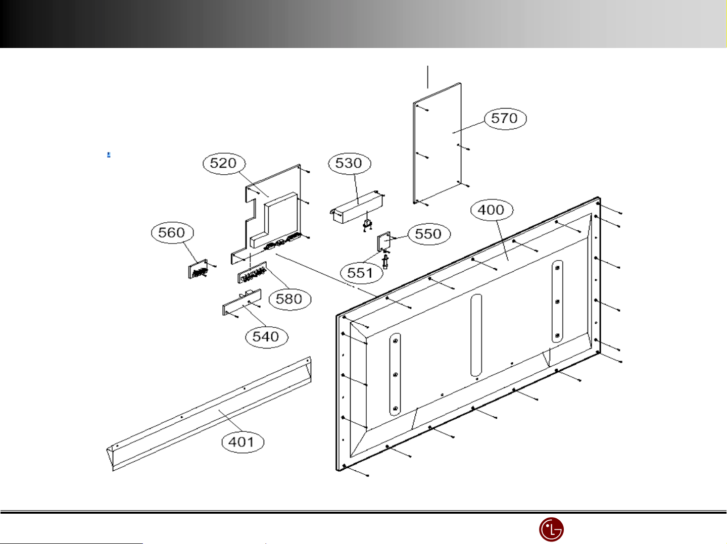
Exploded view (Back Cover, VSC, EMI, Power )
Exploded view (Back Cover, VSC, EMI, Power )
Exploded view (Back Cover, VSC, EMI, Power )Exploded view (Back Cover, VSC, EMI, Power )
VSC BOARDEMI Filter
VSC BOARDVSC BOARD
EMI Filter
EMI FilterEMI Filter
POWER BOARD
POWER BOARDVSC BOARD
POWER BOARDPOWER BOARD
BACK COVER
BACK COVER
BACK COVERBACK COVER
LG Electronics/DND QA
LG Electronics/DND QA Gr
LG Electronics/DND QA LG Electronics/DND QA
Gr
GrGr
Page 16
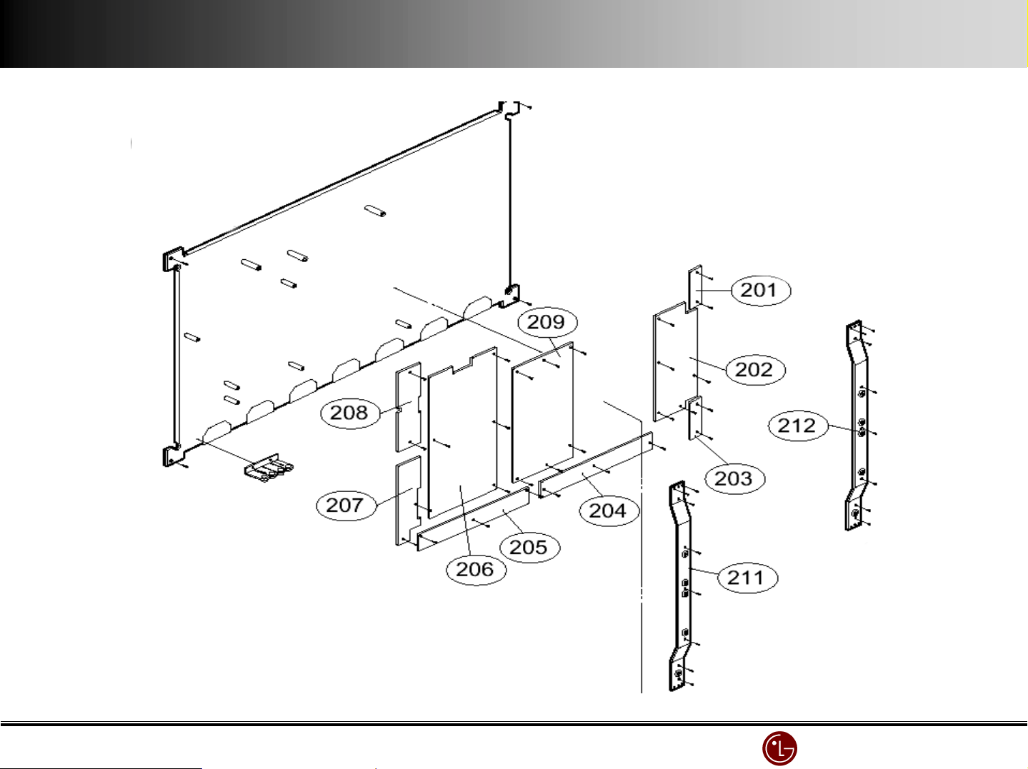
PANEL
PANEL
PANELPANEL
CONTROL
CONTROL
CONTROLCONTROL
BOARD
BOARD
BOARDBOARD
Exploded view (Module)
Exploded view (Module)
Exploded view (Module)Exploded view (Module)
ZZZZ----BOARD
BOARD
BOARDBOARD
YYYY----Drive BOARD
Drive BOARD
Drive BOARDDrive BOARD
YYYY----Drive BOARD
Drive BOARD
Drive BOARDDrive BOARD
YYYY----BOARD
BOARD
BOARDBOARD
XXXX----BOARD
XXXX----BOARD
BOARD
BOARDBOARD
BOARD
BOARDBOARD
LG Electronics/DND QA
LG Electronics/DND QA Gr
LG Electronics/DND QA LG Electronics/DND QA
Gr
GrGr
Page 17
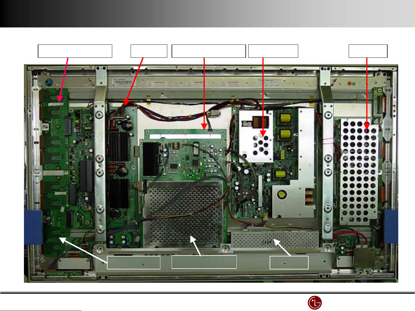
Drive Board (Top)
Drive Board (Top)Drive Board (Top)
Board Control Board(Back)
BoardBoard
Control Board(Back)YYYY----Drive Board (Top)
Control Board(Back)Control Board(Back)
Parts (back covers open)
Parts (back covers open)
Parts (back covers open)Parts (back covers open)
Power Board
Power Board ZZZZ----Board
Power BoardPower Board
BoardYYYY----Board
BoardBoard
YYYY----3*8v/(B+a*d
3*8v/(B+a*d
3*8v/(B+a*d3*8v/(B+a*d
VSC Board(Front)
VSC Board(Front)
VSC Board(Front)VSC Board(Front)
EMI Filter
EMI Filter
EMI FilterEMI Filter
Main Power
Main Power
Main Power Main Power
Switch
Switch
SwitchSwitch
LG Electronics/DND QA
LG Electronics/DND QA Gr
LG Electronics/DND QA LG Electronics/DND QA
Gr
GrGr
Page 18
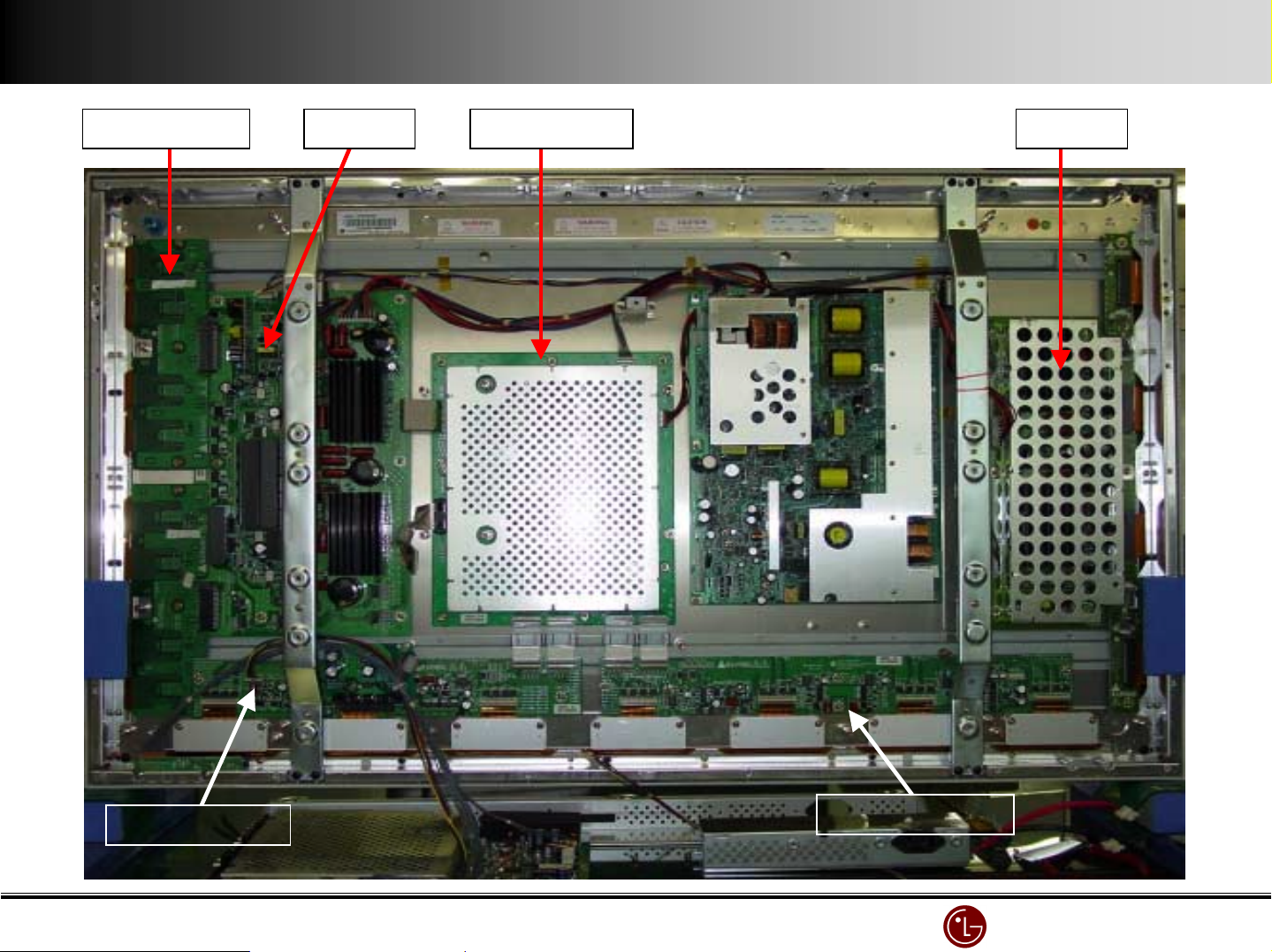
Drive Board
Drive BoardDrive Board
BoardYYYY----Drive Board
BoardBoard
EMI Filter & VSC Board are separated
EMI Filter & VSC Board are separated
EMI Filter & VSC Board are separatedEMI Filter & VSC Board are separated
Control Board
Control Board ZZZZ----Board
Control BoardControl Board
BoardYYYY----Board
BoardBoard
XXXX----Board ( Left )
Board ( Left )
Board ( Left )Board ( Left )
XXXX----Board ( Right)
Board ( Right)
Board ( Right) Board ( Right)
LG Electronics/DND QA
LG Electronics/DND QA Gr
LG Electronics/DND QA LG Electronics/DND QA
Gr
GrGr
Page 19
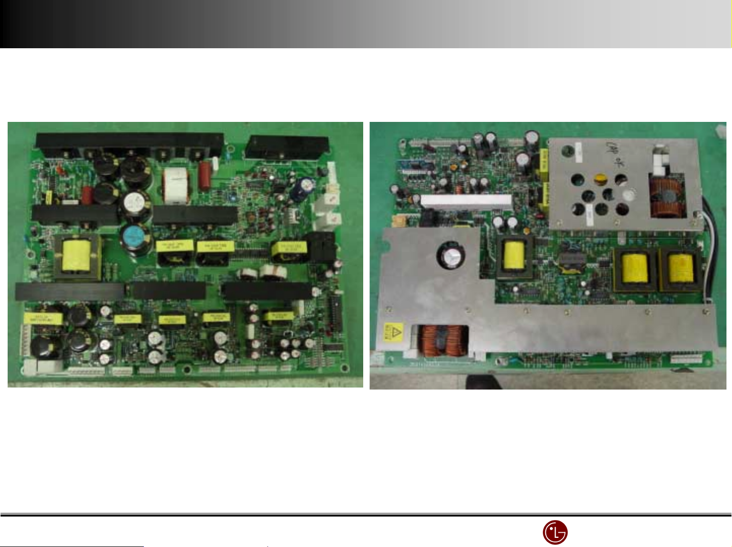
Power Board ( SMPS )
Power Board ( SMPS )
Power Board ( SMPS )Power Board ( SMPS )
Power well power Board-Korean market Murata Power Board
LG Electronics/DND QA
LG Electronics/DND QA Gr
LG Electronics/DND QA LG Electronics/DND QA
Gr
GrGr
Page 20
Ⅲ
Ⅲ.... Screen defect diagnosis
ⅢⅢ
1. The 4/7 or 3/7 of screen is not displayed.
1) Check the X B/D power connector.
2) Check the connector between CTRL B/D and X B/D.
3) Replace the X B/D.
"
" relations between screen and X B/D
""
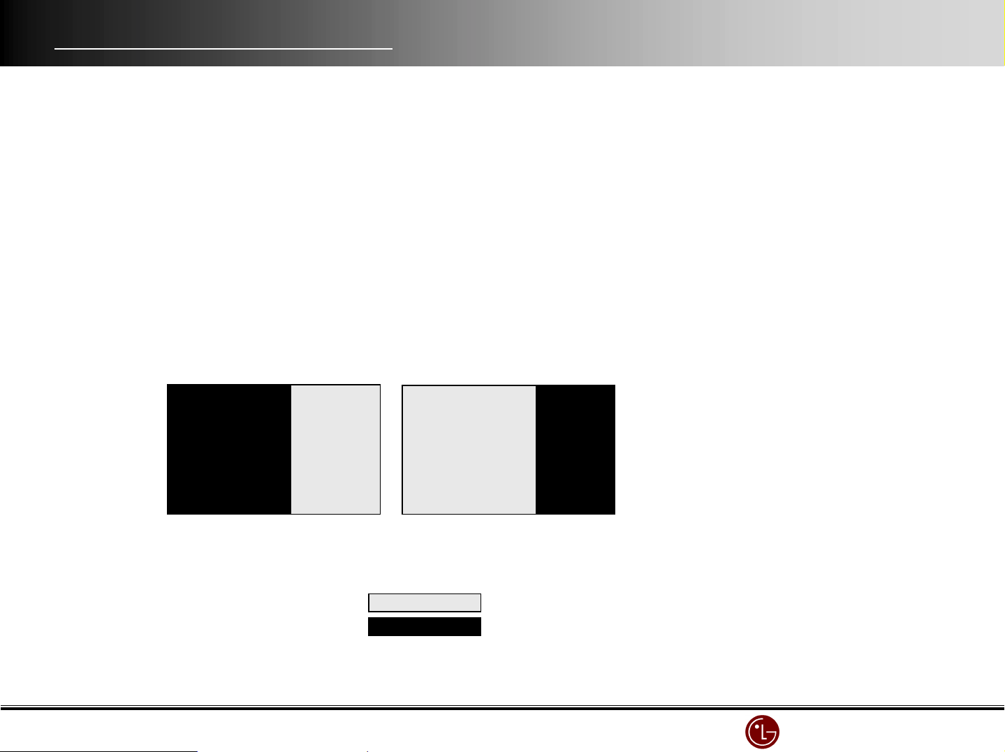
screen X B/D
left 4/7 of screen ↔ Right X B/D
right 3/7 of screen ↔ Left X B/D
"
" type
""
i) screen’s left(4/7)
ii) Screen’s right(3/7)
Displaying part
Non-displaying part
LG Electronics/DND QA
LG Electronics/DND QA Gr
LG Electronics/DND QA LG Electronics/DND QA
Gr
GrGr
Page 21
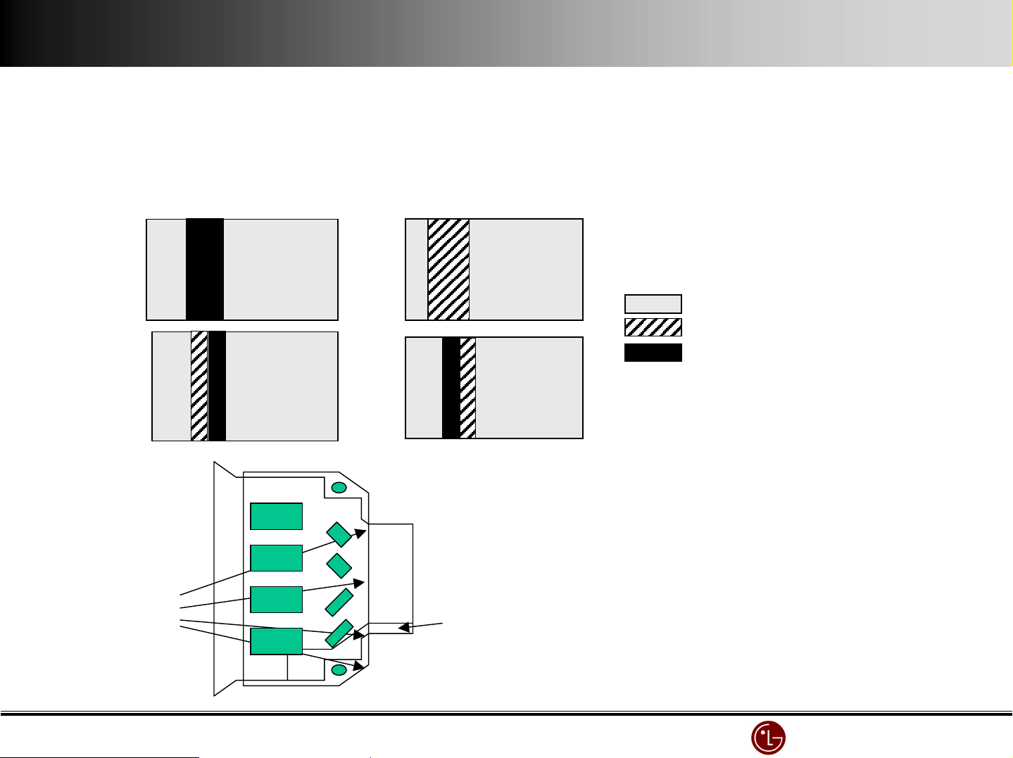
2. No image by Data COF. (the case one Data COF is totally or partially not displayed included)
1) It is mainly caused by related Data COF and X B/D connection error.
2) Check the connector between that Data COF & X B/D.
3) When Data COF has a defect, replace the related X B/D.
"
" examples of screen display type
""
( beside the below, any out of 7 Data COF can be occurred. )
ok
partially displaying
Non-image
"
" Data COF IC test method
""
②
resistance
Set ① pattern( GND ) to ANODE,
② Pattern (resistance joint part ) to CATHOD,
Test diode forward and backward.
Measure @ resistance value.(10A)
① GND
LG Electronics/DND QA
LG Electronics/DND QA Gr
LG Electronics/DND QA LG Electronics/DND QA
Gr
GrGr
Page 22
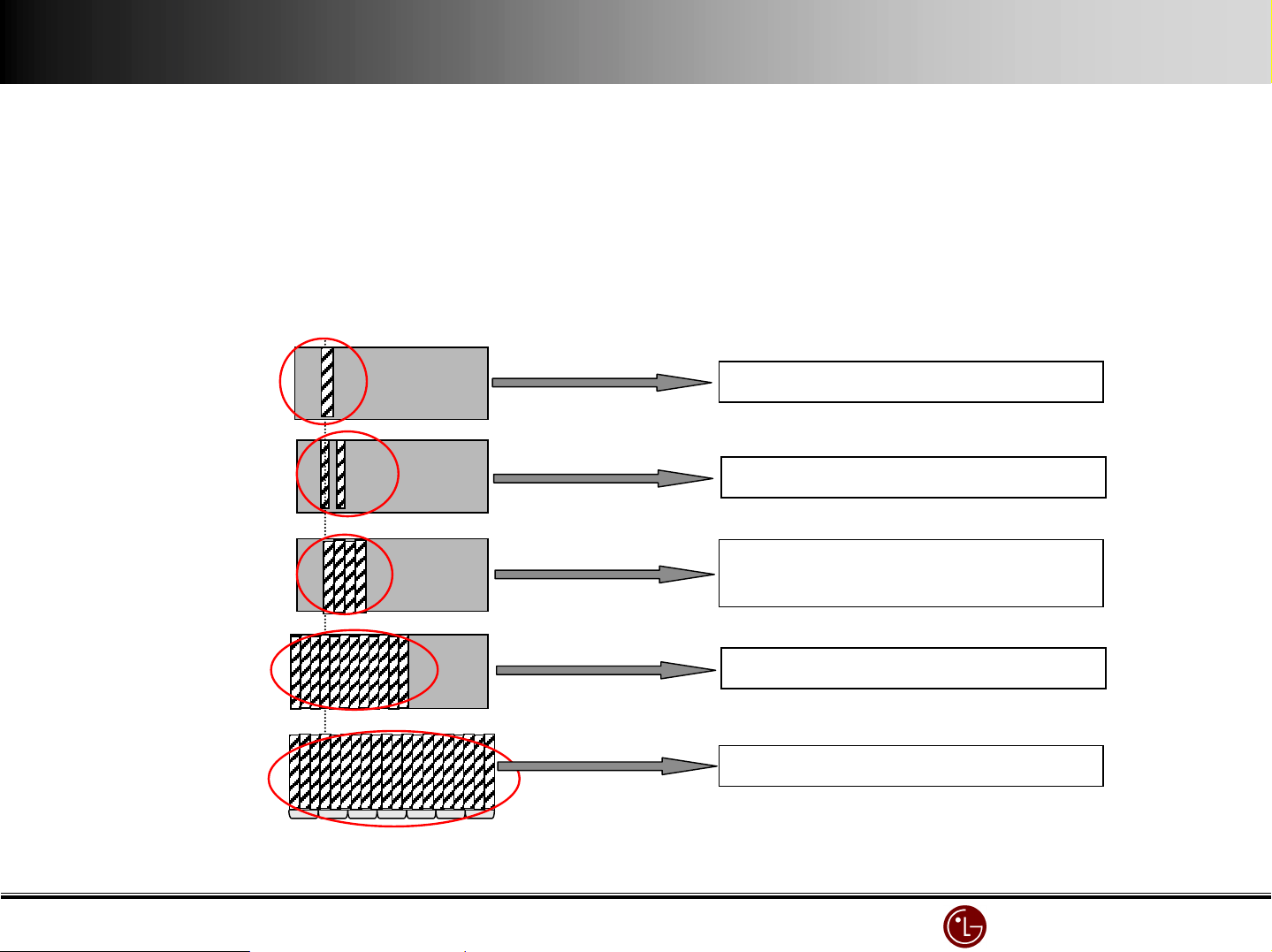
3. Data COF IC unit error
1) As pictures below, this is caused by the clock error of Data COF IC
2) With <case 1>, <case 2>, <case 3>, check Data COF connector and replace the X B/D.
3) With <case 4>, <case 5>, check the connector between CTRL B/D & X B/D and replace X B/D or CTRL B/D.
"
" Cases
""
<case 1>
<case 2>
<case 3>
<case 4>
<case 5>
One IC error in one COF
Two every-second IC error in one
4 IC errors in one COF
Data COF IC unit error in the whole X B/D
Data COF IC unit error in the whole screen.
LG Electronics/DND QA
LG Electronics/DND QA Gr
LG Electronics/DND QA LG Electronics/DND QA
Gr
GrGr
Page 23
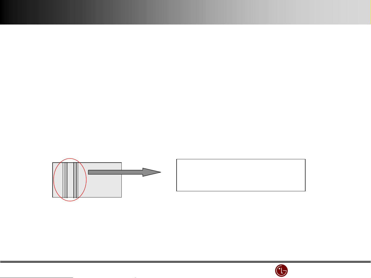
4. Regular vertical line with one or more Data COF IC
1) Regular vertical line with one Data COF IC is mainly caused by X B/D output terminal buffer’s output error. When two Data COF ICs have regular
vertical lines, it means the data transfer from Controller B/D to X B/D has an error.
2) Check the related X B/D connector.
3) Replace that X B/D or CTRL B/D
"
" relation between screen & X B/D
""
screen X B/D
left 4/7 of bottom screen ↔ Right X B/D
right 3/7 of bottom screen ↔ Left X B/D
"
" case
""
Partial error or total error with One or more ICs
defect.
LG Electronics/DND QA
LG Electronics/DND QA Gr
LG Electronics/DND QA LG Electronics/DND QA
Gr
GrGr
Page 24
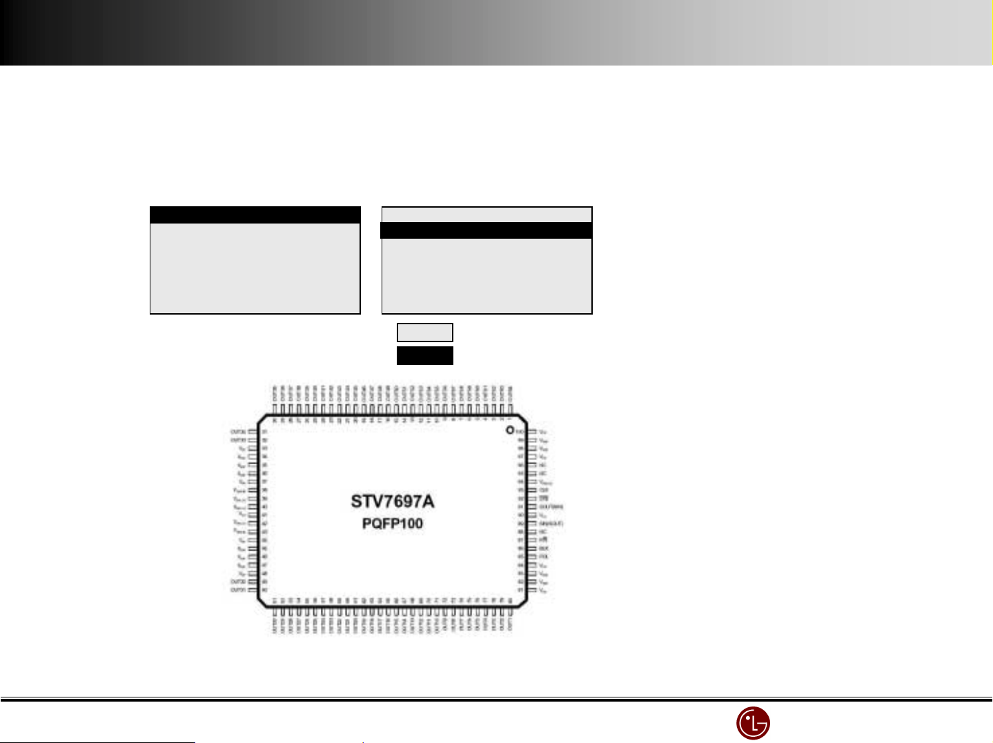
5. The screen by Scan FFC is not displayed
1) It is mainly caused by the bad connection between Scan FFC & Y B/D.
2) Check the related connector between Scan COF & Y B/D.
3) When Scan IC has a defect, replace the related Y DRV B/D.
"
" case
""
"
" SCAN IC check
""
1/8 of the screen
B
B
B
OK
total or partial non- image
Set Vpp Pin to ANODE, GND pin to CATHOD and test diode forward and backward.
LG Electronics/DND QA
LG Electronics/DND QA Gr
LG Electronics/DND QA LG Electronics/DND QA
Gr
GrGr
Page 25
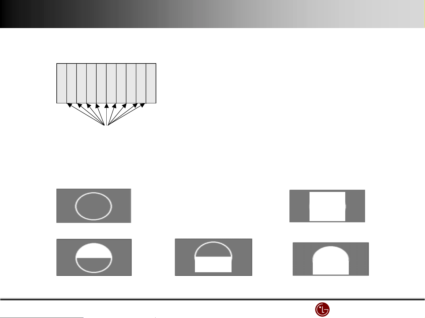
6. Regular vertical lines in the whole screen. (mainly in one specific color, regular line is flicking)
1) This problem is related to CONTROL B/D.
2) Replace CONTROL B/D
"
"case
""
Regular vertical lines in the whole screen
7. Vertical Dat a copy
1) It possibly happens when scan wave does not form properly.
2) Replace Y DRVB/D or Y SUS B/D
"
" case
""
<pattern supposed to display>
<case 1 : total copy>
<case2 : partial- top copy> <case 3 : partial- bottom copy> <case 4 : total copy>
LG Electronics/DND QA
LG Electronics/DND QA Gr
LG Electronics/DND QA LG Electronics/DND QA
Gr
GrGr
Page 26
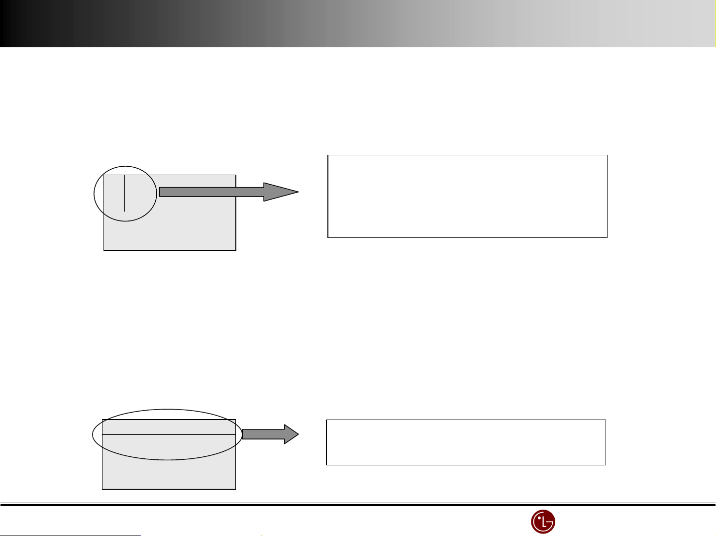
8. One or more vertical lines in th e screen.
1) Irregular vertical line is not related to Controller B/D or X B/D.
2) It is mainly caused by the followings open(or short).
- Panel itself defect
- DATA COF FPC attached to panel is open or short.
- DATA COF attached to panel itself defect
3) Replace module
"
" case
""
9. One or more horizontal lines in the screen.
1) Irregular borizontal line is not related to Controller B/D or Y B/D.
2) It is mainly caused by the followings open(or short).
- Panel itself defect
- SCAN FPC attached to panel is open or short.
- SCAN IC attached to panel itself defect
There are several types.
Several lines in ¼ area.
It can be seen on the both side, right and left.
The area is sometimes over ¼.
3) Replace Y DRV B/D
"
" case
""
Not always like this.
There can be several horizontal lines
LG Electronics/DND QA
LG Electronics/DND QA Gr
LG Electronics/DND QA LG Electronics/DND QA
Gr
GrGr
Page 27
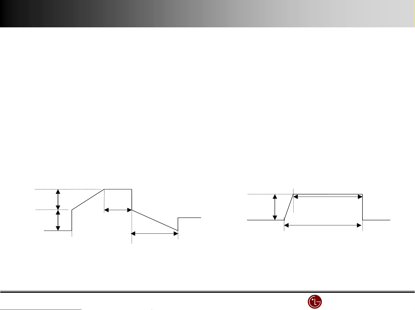
10. Input signal pattern is displayed but the whole brightness of the screen is dark.
1) It happens when Z B/D is not operating well.
2) Check whether Z B/D’s power connector is plugged .
3) Check whether the connector between Controller B/D & Z B/D is plugged.
4) Replace Controller B/D or Z B/D.
11. In full white pattern, foreign color is displayed or in full black pattern, mis-discharge
is partially occurred.
1) Check the slope of Y B/D set up, set down waveform.
2) Check the slope of Z B/D’s ramp waveform
3) Measure each B/D’s output waveform by over 200MHz oscilloscope and compare it to the below picture.
it is possible to control Y B/D’s setup slope by adjustinng VR2, setdown slope by VR1 and Z B/D’s ramp slope by VR1..
- Y B/D measurement point : TP ( Connector P4 36 pin )
- Z B/D measurement point : panel connection part ( SUS_OUT )
230V
Vsetup
175V
0V
Vs
setup
25µs
setdown
230µs
Y output voltage wave
175V
Vs
15µs
20µs
Z RAMP voltage wave
LG Electronics/DND QA
LG Electronics/DND QA Gr
LG Electronics/DND QA LG Electronics/DND QA
Gr
GrGr
Page 28
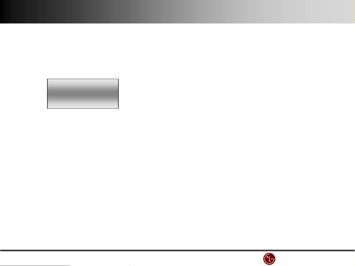
12. In full white pattern, the brightness is getting darker toward the center.
1) It happens with Z B/D’s ramp waveform
2) Check the connection between CTRL B/D and Z B/D’s connection cable.
3) Replace Z B/D.
"
" case
""
13. A specific brightness of one color is not clear.
1) Check CTRL B/D’s input signal connector.
2) Replace CTRL B/D.
LG Electronics/DND QA
LG Electronics/DND QA Gr
LG Electronics/DND QA LG Electronics/DND QA
Gr
GrGr
Page 29
ⅣⅣⅣⅣ.
. Non
Non----picture
. .
NonNon
picture Defect diagnosis.
picturepicture
Defect diagnosis.
Defect diagnosis.Defect diagnosis.
Non- image or same symptom when power off or black pattern.
1) Check CTRL B/D’s LED(D1~D4).
2) Check the power or signal cable input into CTRL B/D.
3) Check X B/D, Y B/D and Z B/D’s power connector.
4) Check the connector between CTRL B/D and X B/D, Y B/D, Z B/D respectively.
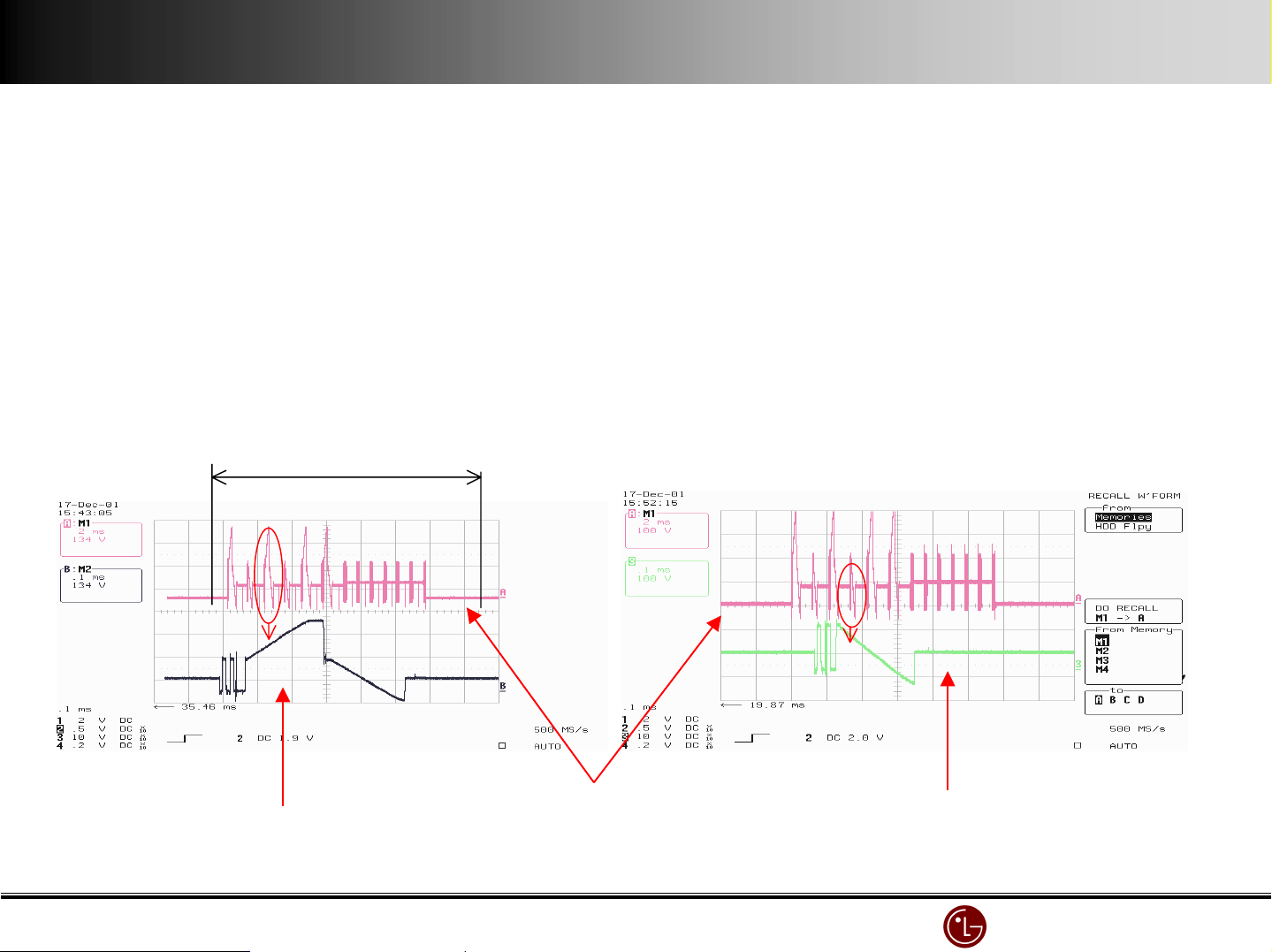
5) Measure each X, Y, Z B/D’s output waveform with over 200MHz oscilloscope and compare it to the below picture to detect the defect
and replace that.
- Y B/D measurement point : TP ( Connector P4 36 pin )
- Z B/D measurement point : panel connection part ( SUS_OUT )
- X B/D measurement point : L1(RIGHT), L2(LEFT BOTTOM)
6)Test scan(Y) IC.
7)Test data(X) COF IC
8)Replace CTRL B/D.
1Frame(16.7ms)
5) Test scan(Y) IC.
6) Test data(X) COF IC.
7) Replace CTRL B/D.
< A: Y B/D output waveform - 1 FRAME >
< B: Y B/D output waveform - 1 SF >
< B: Y B/D output waveform - 2 SF(non-Setup SF) >
LG Electronics/DND QA
LG Electronics/DND QA Gr
LG Electronics/DND QA LG Electronics/DND QA
Gr
GrGr
Page 30
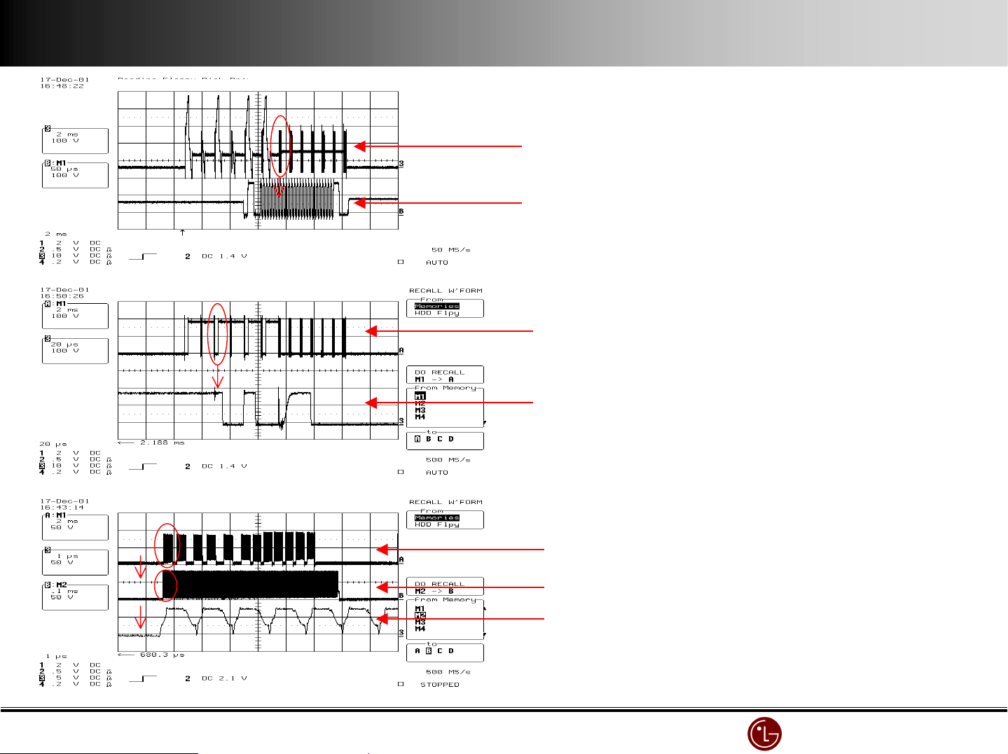
< A: Y B/D output waveform - 1Frame >
< B: Y B/D output waveform - 7~12 SF(SE) >
< A: Z B/D output waveform - 1Frame >
< B: Z B/D output waveform - 1SF >
< X B/D output waveform - 1 FRAME >
< X B/D output waveform - 1 SF >
< X B/D output waveform - amplification >
LG Electronics/DND QA
LG Electronics/DND QA Gr
LG Electronics/DND QA LG Electronics/DND QA
Gr
GrGr
Page 31
ⅤⅤⅤⅤ.
. One Point Service Guide
One Point Service Guide
. .
One Point Service GuideOne Point Service Guide
PDP Flicker and
42
42
4242
42
42
4242
PDP Flicker and
”
PDP Flicker and PDP Flicker and
PDP Flicker and
PDP Flicker and
”
PDP Flicker and PDP Flicker and
No Raster Troubleshooting
No Raster Troubleshooting
No Raster TroubleshootingNo Raster Troubleshooting
No Raster Troubleshooting
No Raster Troubleshooting
No Raster TroubleshootingNo Raster Troubleshooting
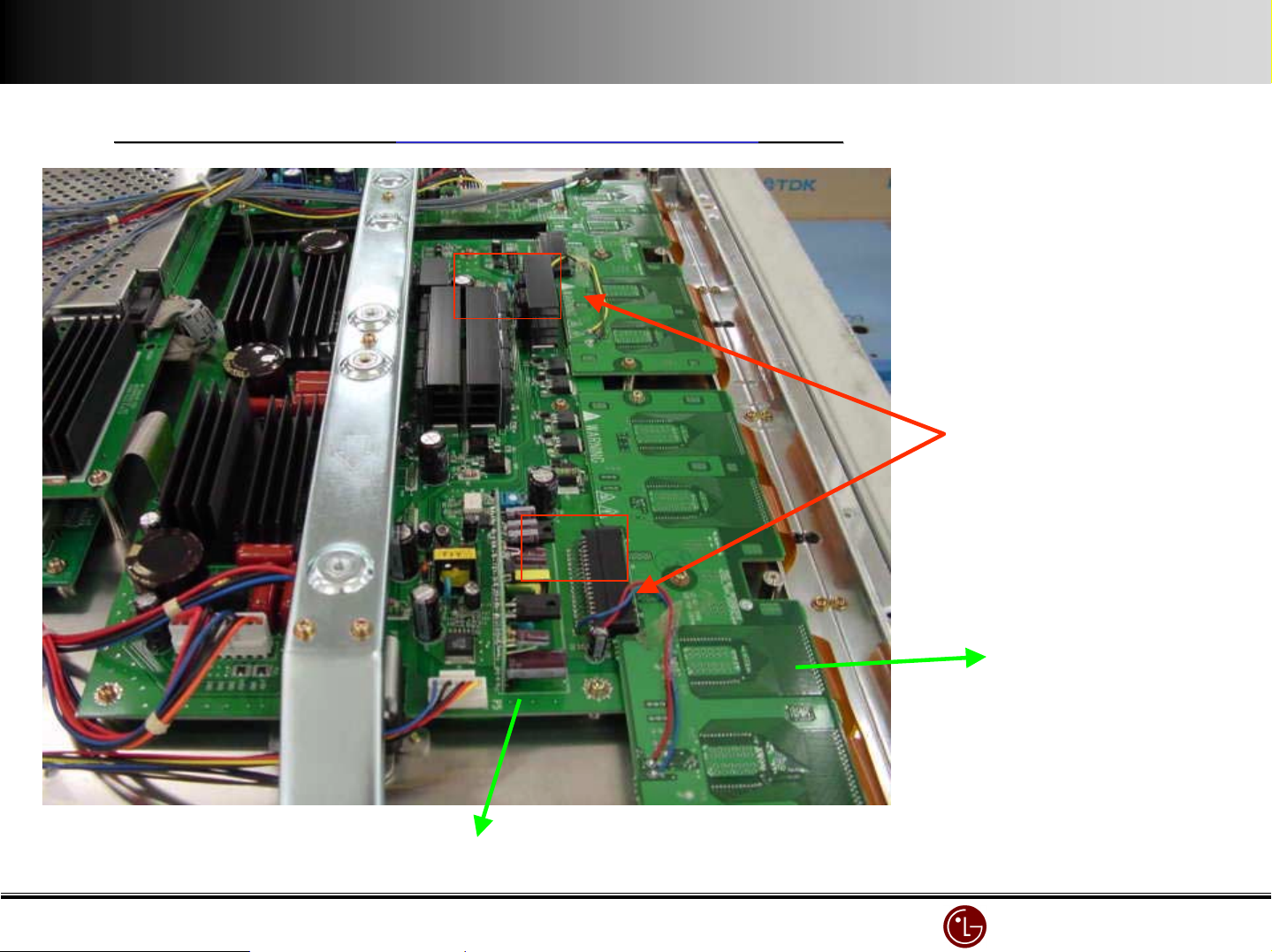
P6
P4
Guide
Guide
GuideGuide
Guide
Guide
GuideGuide
42
42 Inch
Inch
42 42
InchInch
cause : bad connection between
Y-Board
# 1, 2 drive board Connector pin
Rework should
be done
Y-Board
Y-Driver Board
LG Electronics/DND QA
LG Electronics/DND QA Gr
LG Electronics/DND QA LG Electronics/DND QA
Gr
GrGr
Page 32
D
P 6
C
C
D
amplified
D
D
C : outside Leg
D : inside Leg
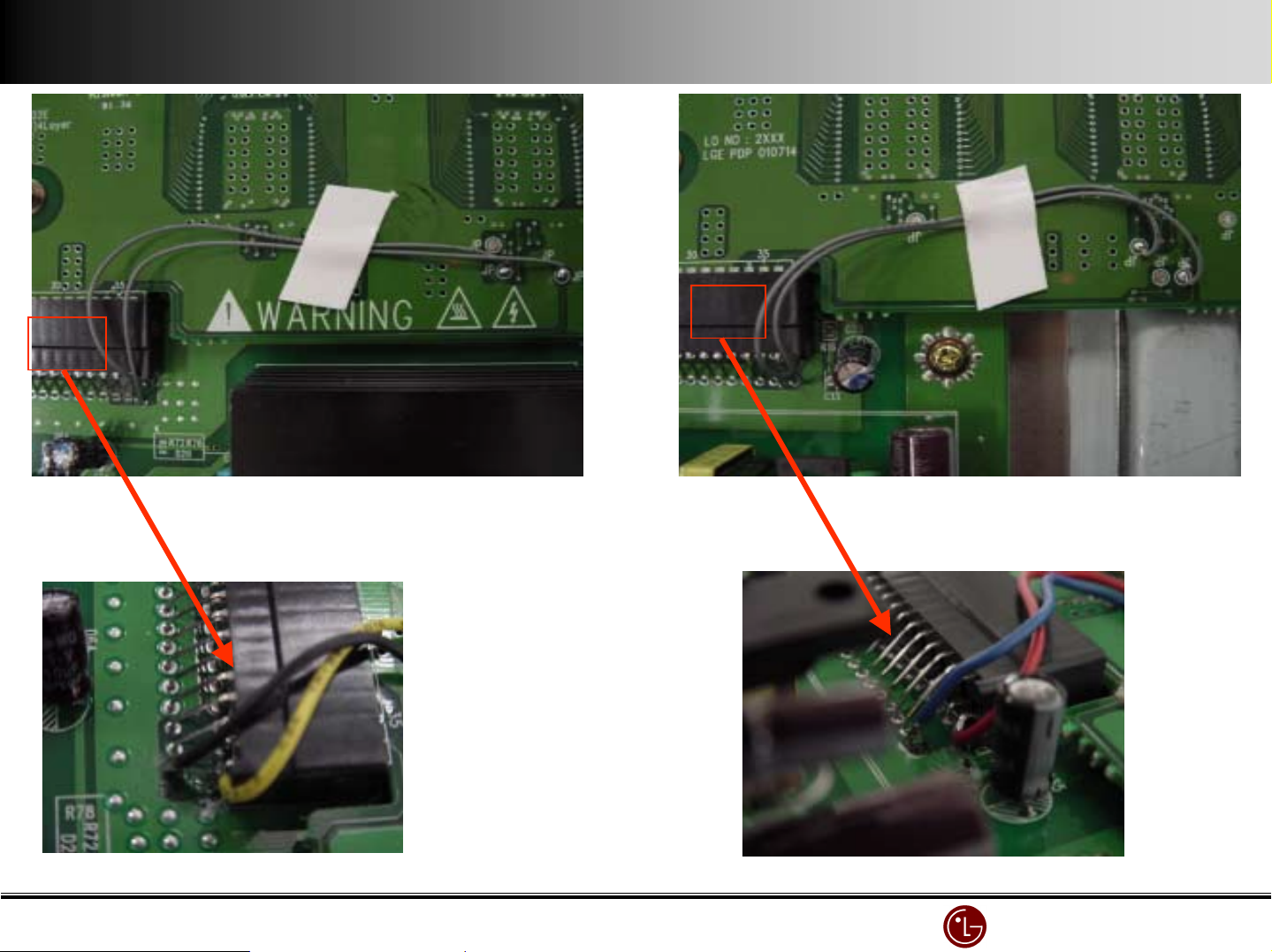
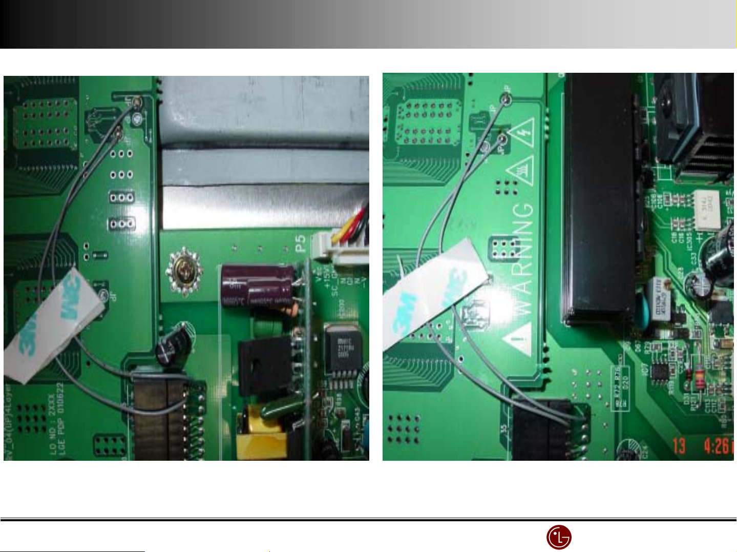
•P 6, P 4 both are the first pin, when
wiring, it should be done as picture
shown.
(bend the wire to Y-Driver B/D not
to Y-B/D . If not there can be noise)
•Don’t be confused with Pin number
•Improved since Dec,2001.
C
P 4
C
D
C
amplified
C
D
LG Electronics/DND QA
LG Electronics/DND QA Gr
LG Electronics/DND QA LG Electronics/DND QA
Gr
GrGr
Page 33
D
C
C
D
D
C
Be sure not to misconnect the line.
Be sure not to misconnect the line.
Be sure not to misconnect the line.Be sure not to misconnect the line.
See the picture precisely and then connect jump wire at the exac
See the picture precisely and then connect jump wire at the exact point
See the picture precisely and then connect jump wire at the exacSee the picture precisely and then connect jump wire at the exac
t point
t pointt point
D
C
LG Electronics/DND QA
LG Electronics/DND QA Gr
LG Electronics/DND QA LG Electronics/DND QA
Gr
GrGr
Page 34
Intermittent no
Intermittent no----image/image error while watching
Intermittent noIntermittent no
image/image error while watching
image/image error while watchingimage/image error while watching
CANVAS
X
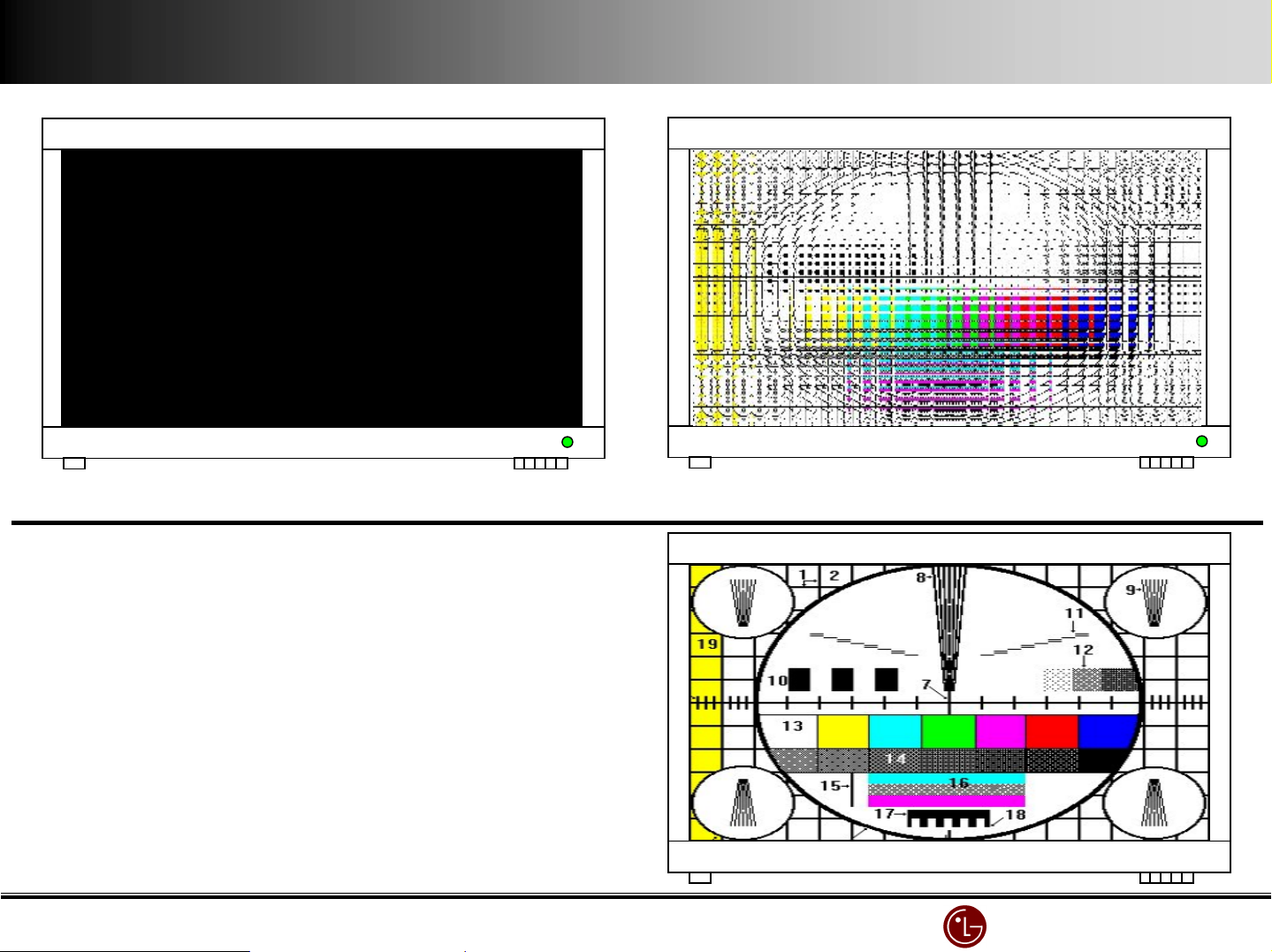
The screen is intermittently disappeared . LED is green
The screen is intermittently disappeared . LED is green
The screen is intermittently disappeared . LED is greenThe screen is intermittently disappeared . LED is green
cause : bad connection between Y
cause : bad connection between Y----Board and ##, 2 pin of
cause : bad connection between Ycause : bad connection between Y
YYYY----Drive Board Connector
Drive Board Connector
Drive Board Connector Drive Board Connector
Board and ##, 2 pin of
Board and ##, 2 pin ofBoard and ##, 2 pin of
CAVBAS
X
screen is distorted
screen is distorted weiderly
screen is distorted screen is distorted
CANVAS
X
weiderly (happened 2 a day)
weiderlyweiderly
(happened 2 a day)
(happened 2 a day)(happened 2 a day)
troubleshooting : connect bad linking between Y
troubleshooting : connect bad linking between Y----Board &
troubleshooting : connect bad linking between Ytroubleshooting : connect bad linking between Y
YYYY----Drive with jump wire (all 4 parts)
Drive with jump wire (all 4 parts)
Drive with jump wire (all 4 parts)Drive with jump wire (all 4 parts)
see working instruction(revised since Dec,200#. #)
see working instruction(revised since Dec,200#. #)
see working instruction(revised since Dec,200#. #)see working instruction(revised since Dec,200#. #)
Board &
Board & Board &
normal
normal
normalnormal
LG Electronics/DND QA
LG Electronics/DND QA Gr
LG Electronics/DND QA LG Electronics/DND QA
Gr
GrGr
Page 35
No Power
No Power
No PowerNo Power
CANVAS
X
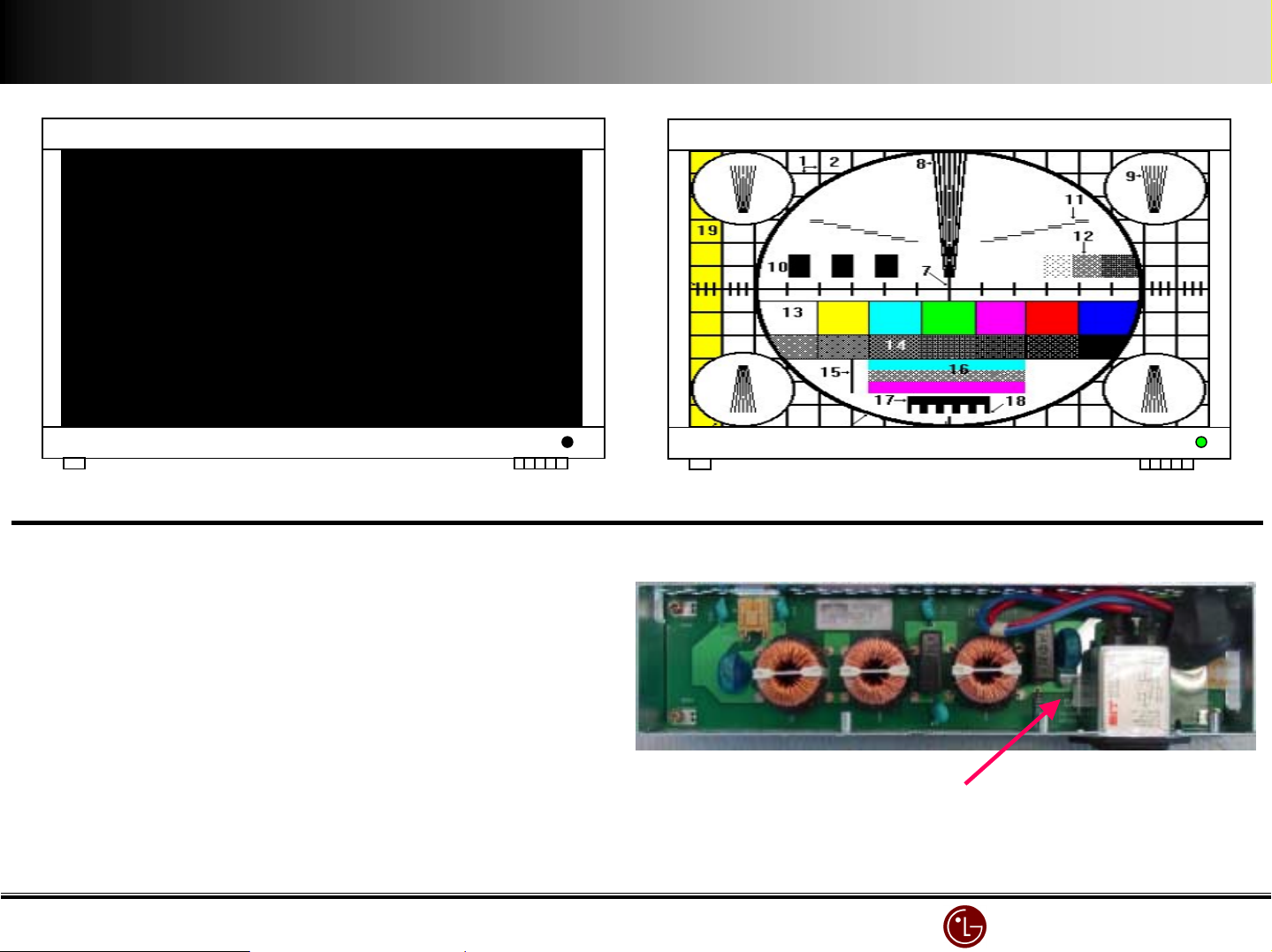
No Power
No Power
No Power No Power
( in ST
( in ST----BY mode, but no LED)
( in ST( in ST
Check the power supply & main power S/W on
Check the power supply & main power S/W on
Check the power supply & main power S/W onCheck the power supply & main power S/W on
BY mode, but no LED)
BY mode, but no LED)BY mode, but no LED)
CANVAS
X
normal
normal
normalnormal
Check EMI board fuse (check the rated capacity )
Check EMI board fuse (check the rated capacity )
Check EMI board fuse (check the rated capacity )Check EMI board fuse (check the rated capacity )
Be sure to use rated fuse.
Be sure to use rated fuse.
Be sure to use rated fuse.Be sure to use rated fuse.
Fuse #5 A
Fuse #5 A
Fuse #5 AFuse #5 A
LG Electronics/DND QA
LG Electronics/DND QA Gr
LG Electronics/DND QA LG Electronics/DND QA
Gr
GrGr
Page 36
No Raster
No Raster
No RasterNo Raster
CAVBAS
X
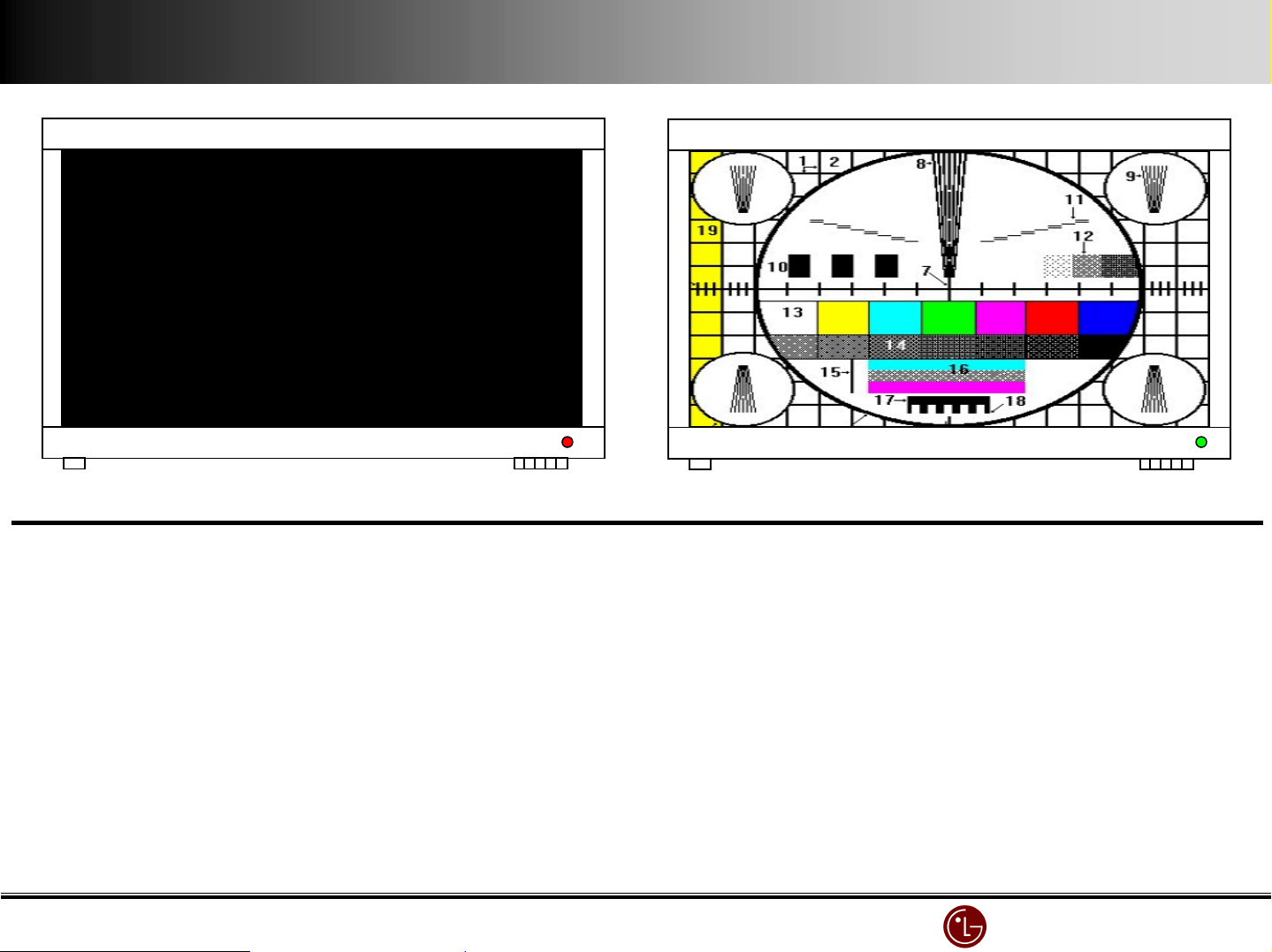
when Power
when Power’s on, after 2 ~ 3 sec, it
when Powerwhen Power
( LED changing green into red )
( LED changing green into red )
( LED changing green into red )( LED changing green into red )
CHECK : remove STB and operate monitor individually.
CHECK : remove STB and operate monitor individually.
CHECK : remove STB and operate monitor individually.CHECK : remove STB and operate monitor individually.
(check STB defect or Monitor defect )
(check STB defect or Monitor defect )
(check STB defect or Monitor defect )(check STB defect or Monitor defect )
s on, after 2 ~ 3 sec, it’s off
s on, after 2 ~ 3 sec, its on, after 2 ~ 3 sec, it
s off
s offs off
CANVAS
X
normal
normal
normalnormal
When using ANALOG STB, check STB only
When using ANALOG STB, check STB only
When using ANALOG STB, check STB onlyWhen using ANALOG STB, check STB only
MN
MN----42PZ#0 only STB : RN
42PZ#0 only STB : RN----BA##
MNMN
42PZ#0 only STB : RN42PZ#0 only STB : RN
Remove each Board
Remove each Board’s power supply connector and check the power is off.
Remove each BoardRemove each Board
When the power is not off,replace the related board.
When the power is not off,replace the related board.
When the power is not off,replace the related board.When the power is not off,replace the related board.
s power supply connector and check the power is off.
s power supply connector and check the power is off.s power supply connector and check the power is off.
BA##
BA##BA##
LG Electronics/DND QA
LG Electronics/DND QA Gr
LG Electronics/DND QA LG Electronics/DND QA
Gr
GrGr
Page 37
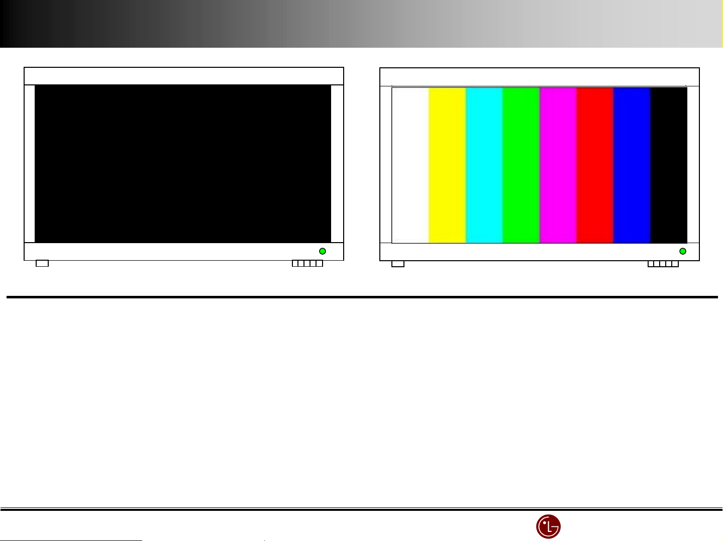
CANVAS
X
no picture (LED
no picture (LED’s green)
no picture (LEDno picture (LED
s green)
s green)s green)
CANVAS
X
normal
normal
normalnormal
No Picture
No Picture
No PictureNo Picture
Core checkpoint : remove STB and operate monitor individually.
Core checkpoint : remove STB and operate monitor individually.
Core checkpoint : remove STB and operate monitor individually.Core checkpoint : remove STB and operate monitor individually.
(check whether
(check whether STB
(check whether (check whether
With monitor defect, check VSC and then
With monitor defect, check VSC and then Controller Board.
With monitor defect, check VSC and thenWith monitor defect, check VSC and then
Troubleshooting : replace VSC Board
Troubleshooting : replace VSC Board
Troubleshooting : replace VSC Board Troubleshooting : replace VSC Board
STB’s
s a defect or monitor
STBSTB
a defect or monitor’s one)
s s
a defect or monitora defect or monitor
s one)
s one)s one)
Controller Board.
Controller Board.Controller Board.
LG Electronics/DND QA
LG Electronics/DND QA Gr
LG Electronics/DND QA LG Electronics/DND QA
Gr
GrGr
Page 38
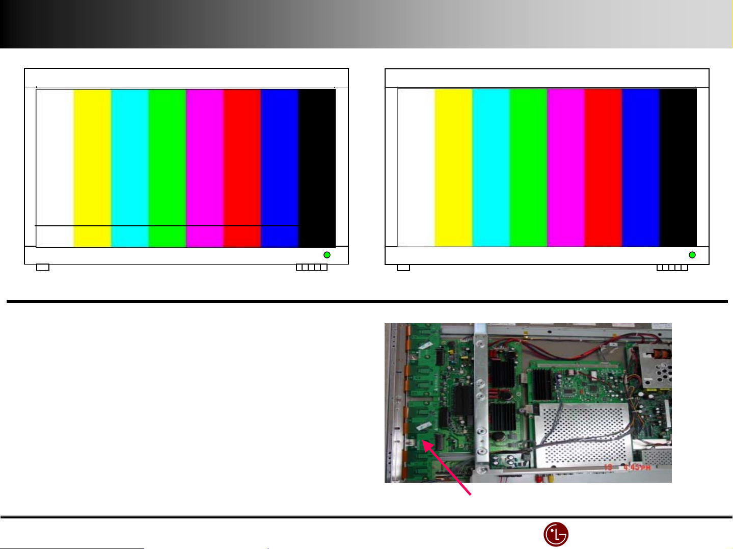
Address Bar ( Horizontal Bar )
Address Bar ( Horizontal Bar )
Address Bar ( Horizontal Bar )Address Bar ( Horizontal Bar )
CANVAS
X
no image (LED
no image (LED’s green)
no image (LEDno image (LED
s green)
s green)s green)
CANVAS
X
normal
normal
normalnormal
Cause : Y
Cause : Y----Drive ( Bottom ) defect
Cause : YCause : Y
Troubleshooting : Y
Troubleshooting : Y----Drive (lower part) replacement
Troubleshooting : YTroubleshooting : Y
This problem is shown in the bottom of screen,
This problem is shown in the bottom of screen,
This problem is shown in the bottom of screen,This problem is shown in the bottom of screen,
So it is caused by Y
So it is caused by Y----Drive
So it is caused by YSo it is caused by Y
Drive ( Bottom ) defect
Drive ( Bottom ) defectDrive ( Bottom ) defect
Drive (lower part) replacement
Drive (lower part) replacement Drive (lower part) replacement
Drive
Drive Drive
YYYY----Drive Board ( Bottom )
Drive Board ( Bottom )
Drive Board ( Bottom )Drive Board ( Bottom )
LG Electronics/DND QA
LG Electronics/DND QA Gr
LG Electronics/DND QA LG Electronics/DND QA
Gr
GrGr
Page 39
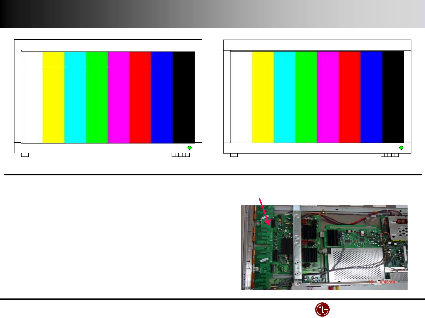
Address Bar ( Horizontal Bar )
Address Bar ( Horizontal Bar )
Address Bar ( Horizontal Bar )Address Bar ( Horizontal Bar )
CANVAS
X
no image (LED
no image (LED’s green)
no image (LEDno image (LED
Cause : Y
Cause : Y----Drive Board (upper part) defect
Cause : YCause : Y
Drive Board (upper part) defect
Drive Board (upper part) defectDrive Board (upper part) defect
s green)
s green)s green)
CANVAS
X
normal
normal
normalnormal
YYYY----Drive Board ( Top )
Drive Board ( Top )
Drive Board ( Top )Drive Board ( Top )
Troubleshooting : Y
Troubleshooting : Y----Drive Board replacement
Troubleshooting : YTroubleshooting : Y
Drive Board replacement
Drive Board replacementDrive Board replacement
LG Electronics/DND QA
LG Electronics/DND QA Gr
LG Electronics/DND QA LG Electronics/DND QA
Gr
GrGr
Page 40
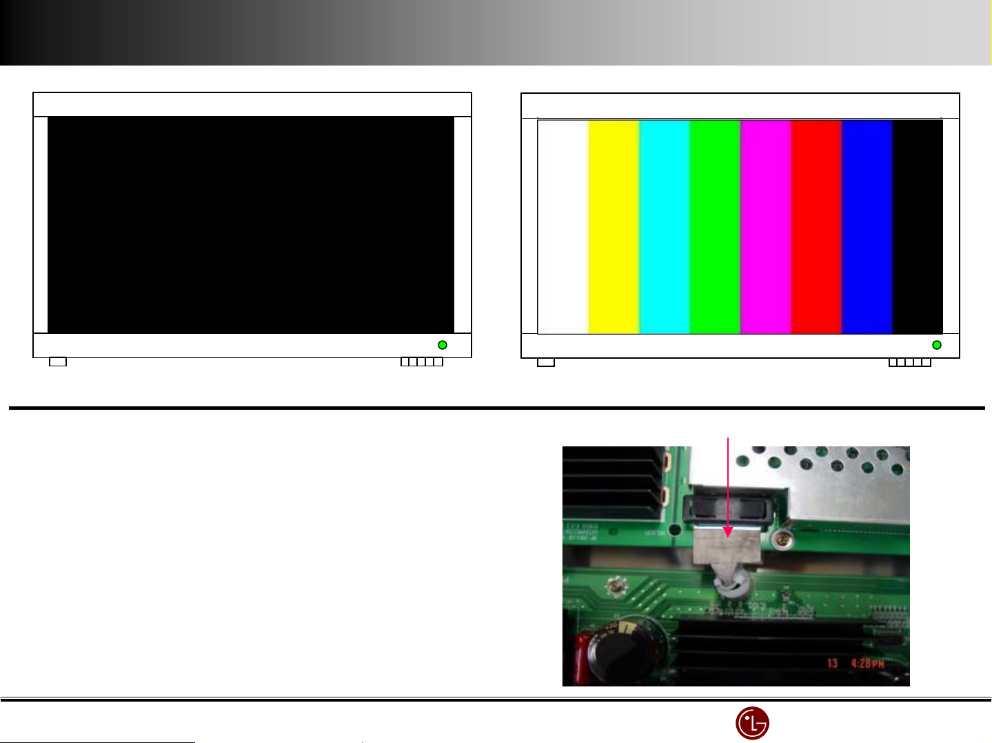
CANVAS
X
no image (LED
no image (LED’s green)
no image (LEDno image (LED
s green)
s green)s green)
CANVAS
X
normal
normal
normalnormal
PD50# Connector
PD50# Connector
PD50# ConnectorPD50# Connector
No Picture
No Picture
No PictureNo Picture
cause : PD
cause : PD----50# Connector contact point defect
cause : PDcause : PD
troubleshooting : PD
troubleshooting : PD----50# Connector replacement
troubleshooting : PDtroubleshooting : PD
(with PD
(with PD----50# Connector contact point defect,
(with PD(with PD
Various defect symptoms can be seen)
Various defect symptoms can be seen)
Various defect symptoms can be seen)Various defect symptoms can be seen)
50# Connector contact point defect
50# Connector contact point defect50# Connector contact point defect
50# Connector replacement
50# Connector replacement50# Connector replacement
50# Connector contact point defect,
50# Connector contact point defect,50# Connector contact point defect,
LG Electronics/DND QA
LG Electronics/DND QA Gr
LG Electronics/DND QA LG Electronics/DND QA
Gr
GrGr
Page 41
High frequency noise (
High frequency noise (“Bee
High frequency noise (High frequency noise (
Bee” sound)
BeeBee
sound)
sound)sound)
CANVAS
X
normal picture with high frequency noise (
normal picture with high frequency noise (“bee
normal picture with high frequency noise (normal picture with high frequency noise (
SMPS is supposed to operate
SMPS is supposed to operate
SMPS is supposed to operateSMPS is supposed to operate
with high frequency so
with high frequency so
with high frequency sowith high frequency so
small noise is not considered
small noise is not considered
small noise is not considered small noise is not considered
as a defect.
as a defect.
as a defect.as a defect.
bee”)
beebee
CANVAS
X
)
))
normal
normal
normalnormal
Power (SMPS) Board
Power (SMPS) Board
Power (SMPS) BoardPower (SMPS) Board
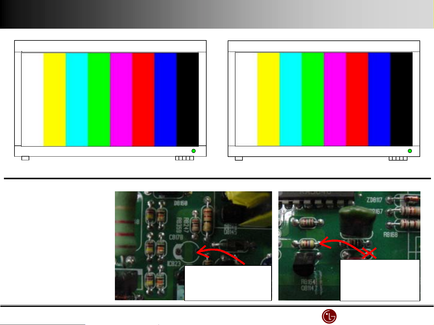
#. C8#78 0.22
#. C8#78 0.22EEEE/50V add
#. C8#78 0.22#. C8#78 0.22
2. Open C8#39 right lead,
2. Open C8#39 right lead,
2. Open C8#39 right lead,2. Open C8#39 right lead,
and then connect it to
and then connect it to
and then connect it toand then connect it to
R8#64 right lead.
R8#64 right lead.
R8#64 right lead.R8#64 right lead.
/50V add
/50V add/50V add
C8#78 0.22uF
electrolytic
Improved since Nov,200#
Improved since Nov,200#
Improved since Nov,200#Improved since Nov,200#
#.
#. Slight noise is not a defect and write down explanation
Slight noise is not a defect and write down explanation
#. #.
Slight noise is not a defect and write down explanationSlight noise is not a defect and write down explanation
capacitor insertion
Open C8#39 right
lead and then
wire R8#64 right
lead
LG Electronics/DND QA
LG Electronics/DND QA Gr
LG Electronics/DND QA LG Electronics/DND QA
Gr
GrGr
Page 42
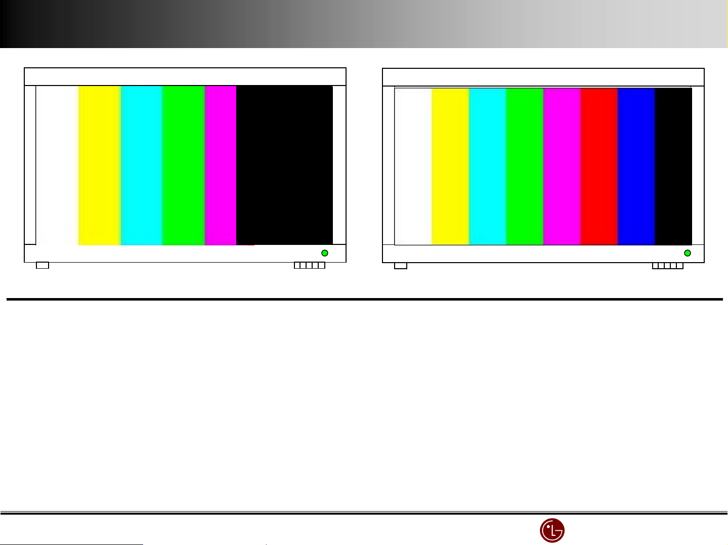
No picture in right
No picture in right----2/5 area
No picture in rightNo picture in right
2/5 area
2/5 area2/5 area
CANVAS
X
No picture in the right
No picture in the right----2/5 area
No picture in the rightNo picture in the right
XXXX----Board ( Left ) power supply check
Board ( Left ) power supply check
Board ( Left ) power supply checkBoard ( Left ) power supply check
2/5 area
2/5 area2/5 area
CANVAS
X
normal
normal
normalnormal
XXXX----Board ( Left )Connector check
Board ( Left )Connector check
Board ( Left )Connector checkBoard ( Left )Connector check
XXXX----Board ( Left ) replacement
Board ( Left ) replacement
Board ( Left ) replacementBoard ( Left ) replacement
LG Electronics/DND QA
LG Electronics/DND QA Gr
LG Electronics/DND QA LG Electronics/DND QA
Gr
GrGr
Page 43
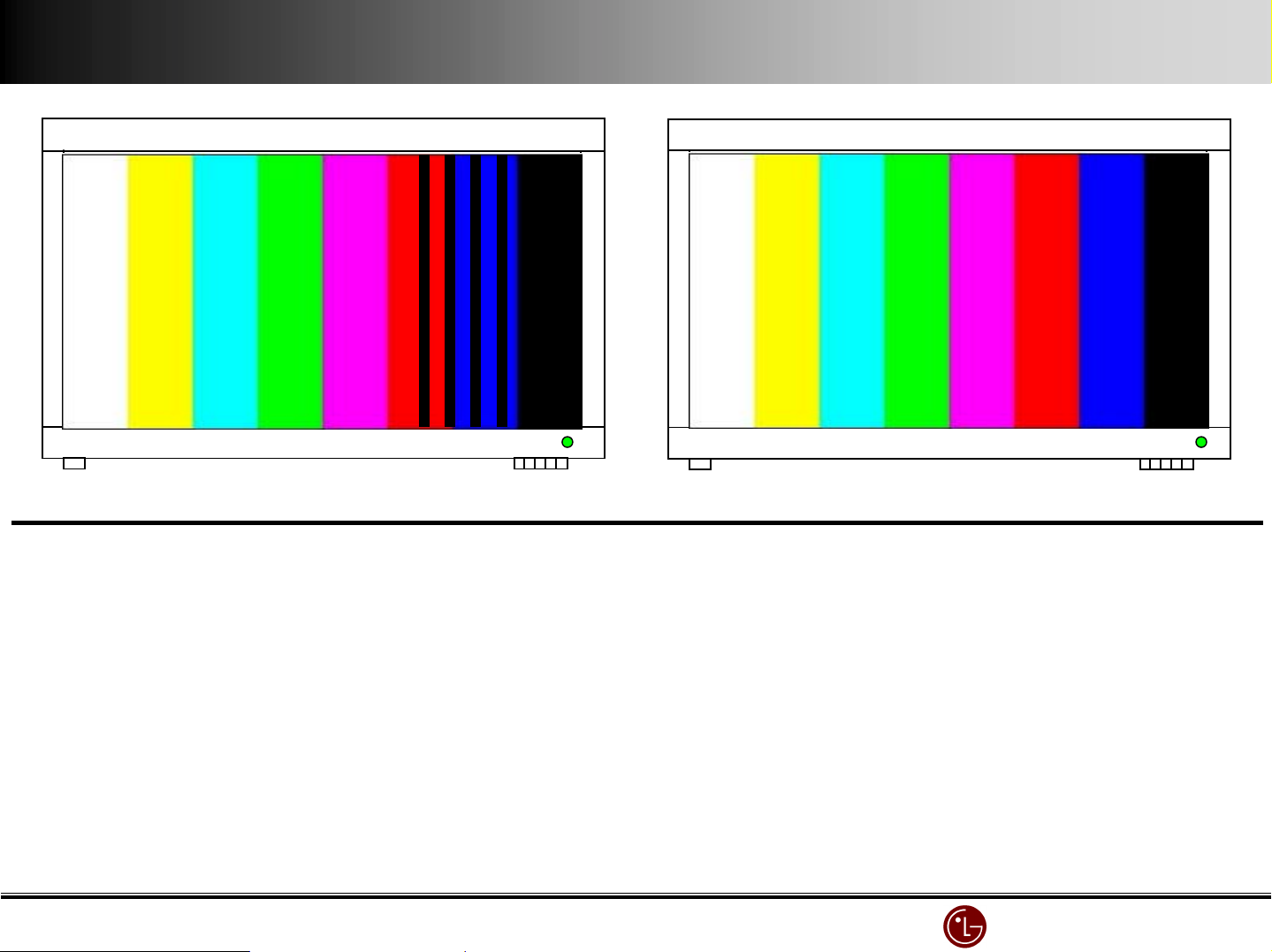
Address Bar (Vertical )
Address Bar (Vertical )
Address Bar (Vertical )Address Bar (Vertical )
CANVAS
X
stripe in right
stripe in right----2/5 area
stripe in rightstripe in right
XXXX----Board ( Left ) power supply check
Board ( Left ) power supply check
Board ( Left ) power supply checkBoard ( Left ) power supply check
XXXX----Board ( Left ) Connector check
Board ( Left ) Connector check
Board ( Left ) Connector checkBoard ( Left ) Connector check
2/5 area
2/5 area2/5 area
CANVAS
X
normal
normal
normalnormal
XXXX----Board ( Left ) replacement
Board ( Left ) replacement
Board ( Left ) replacementBoard ( Left ) replacement
LG Electronics/DND QA
LG Electronics/DND QA Gr
LG Electronics/DND QA LG Electronics/DND QA
Gr
GrGr
Page 44
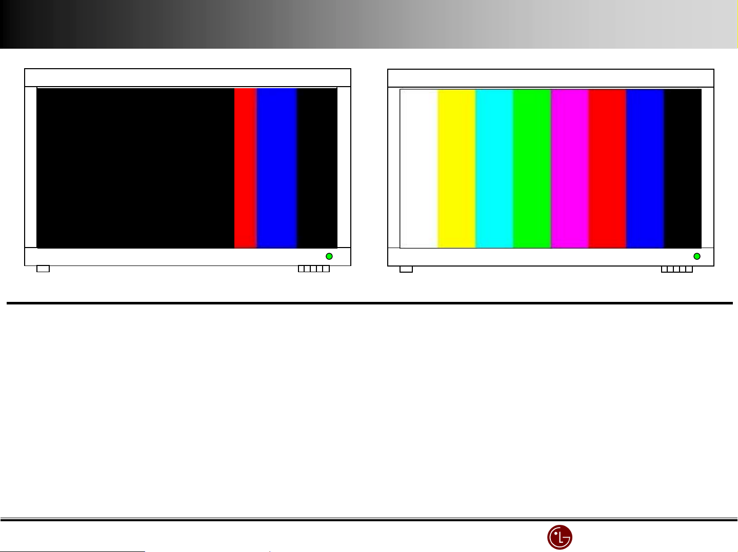
No picture in left 3/5 of the screen
No picture in left 3/5 of the screen
No picture in left 3/5 of the screenNo picture in left 3/5 of the screen
CANVAS
X
left 3/5 of screen with vertical stripes
left 3/5 of screen with vertical stripes
left 3/5 of screen with vertical stripesleft 3/5 of screen with vertical stripes
CANVAS
X
normal
normal
normalnormal
XXXX----Board ( Right ) power supply check
Board ( Right ) power supply check
Board ( Right ) power supply checkBoard ( Right ) power supply check
XXXX----Board ( Right )Connector check
Board ( Right )Connector check
Board ( Right )Connector checkBoard ( Right )Connector check
XXXX----Board ( Right ) replacement
Board ( Right ) replacement
Board ( Right ) replacementBoard ( Right ) replacement
LG Electronics/DND QA
LG Electronics/DND QA Gr
LG Electronics/DND QA LG Electronics/DND QA
Gr
GrGr
Page 45
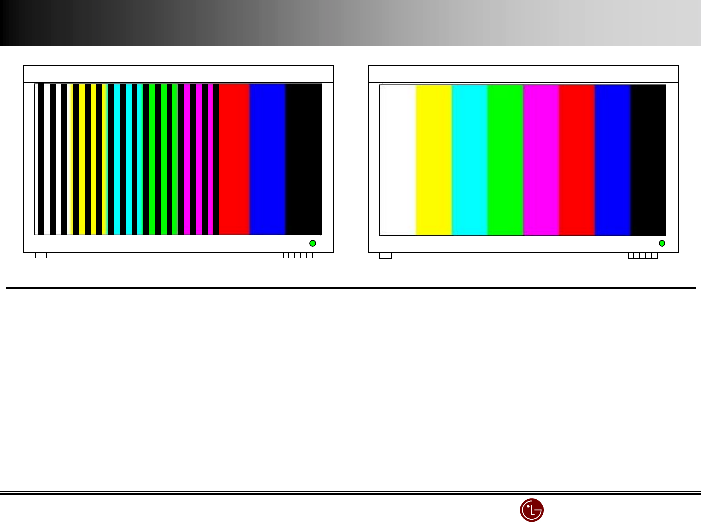
Address Bar (Vertical )
Address Bar (Vertical )
Address Bar (Vertical )Address Bar (Vertical )
CANVAS
X
left 3/5 of screen with vertical stripes.
left 3/5 of screen with vertical stripes.
left 3/5 of screen with vertical stripes.left 3/5 of screen with vertical stripes.
CANVAS
X
normal
normal
normalnormal
XXXX----Board ( Right ) power supply check
Board ( Right ) power supply check
Board ( Right ) power supply checkBoard ( Right ) power supply check
XXXX----Board ( Right )Connector check
Board ( Right )Connector check
Board ( Right )Connector checkBoard ( Right )Connector check
XXXX----Board ( Right ) replacement
Board ( Right ) replacement
Board ( Right ) replacementBoard ( Right ) replacement
LG Electronics/DND QA
LG Electronics/DND QA Gr
LG Electronics/DND QA LG Electronics/DND QA
Gr
GrGr
Page 46
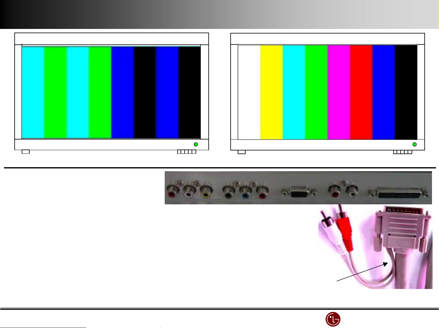
No Red
No Red
No RedNo Red
CANVAS
X
no Red ( B or G )
no Red ( B or G )
no Red ( B or G )no Red ( B or G )
CANVAS
X
normal
normal
normalnormal
Test Monitor individually.
Test Monitor individually.
Test Monitor individually.Test Monitor individually.
If detect a problem with monitor, check VSC Board.
If detect a problem with monitor, check VSC Board.
If detect a problem with monitor, check VSC Board.If detect a problem with monitor, check VSC Board.
If it has a problem with STB connecting, focus on 25 Pin.
If it has a problem with STB connecting, focus on 25 Pin.
If it has a problem with STB connecting, focus on 25 Pin.If it has a problem with STB connecting, focus on 25 Pin.
Be sure not to connect 5 Pin (AP
Be sure not to connect 5 Pin (AP----EA#0) by force
Be sure not to connect 5 Pin (APBe sure not to connect 5 Pin (AP
25
25 Pin Cable P/No : GVZ AP
Pin Cable P/No : GVZ AP----EA#0
25 25
Pin Cable P/No : GVZ APPin Cable P/No : GVZ AP
EA#0) by force
EA#0) by forceEA#0) by force
EA#0
EA#0EA#0
Be sure not to bend it by force or internal
Be sure not to bend it by force or internal
Be sure not to bend it by force or internal Be sure not to bend it by force or internal
Insulated conductor can be down.
Insulated conductor can be down.
Insulated conductor can be down.Insulated conductor can be down.
LG Electronics/DND QA
LG Electronics/DND QA Gr
LG Electronics/DND QA LG Electronics/DND QA
Gr
GrGr
Page 47
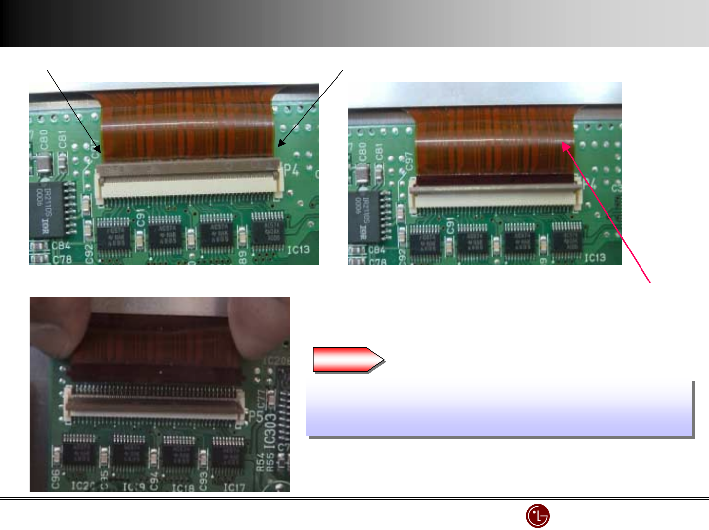
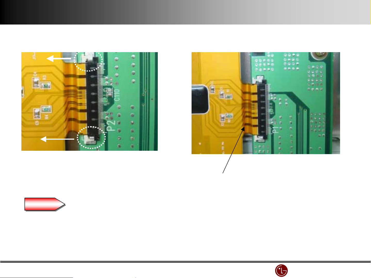
1) X - Board COF Connector separation
42
42 Inch
Inch
42 42
InchInch
Lift up the right and left of X-BOARD CONNECTOR.
When you handle COF CONNECTOR, don’t pressure. First release LOCK and separate.
If COF CONNECTOR is damaged, you should replace MODULE ASS’Y. So, be aware of this!!
Lift up X-BOARD CONNECTOR and separate
COP CONNECTOR by pulling up.
COF Connector
Warning
Warning
When you exchange X-Board, first you should separate COF
When you exchange X-Board, first you should separate COF
Connector. Be careful to handle it.
Connector. Be careful to handle it.
COF Connector is attached to Module. When COF Connector is
COF Connector is attached to Module. When COF Connector is
broken, Module ASS’Y must be replaced a new one.
broken, Module ASS’Y must be replaced a new one.
LG Electronics/DND QA
LG Electronics/DND QA Gr
LG Electronics/DND QA LG Electronics/DND QA
Gr
GrGr
Page 48
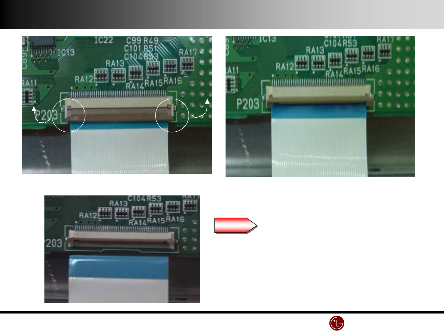
2) X - Board Connector separation
Lift up each edge of left/right. Lifted condition
Be careful to handle LOCK or it can be broken.
When LOCK is broken, replace a new X-BOARD.
Warning
Warning
It’s easy to separate it by releasing Connector Lock .
Do not pressure or it can be hurt.
When LOCK is hurt, replace a new X-BOARD
LG Electronics/DND QA
LG Electronics/DND QA Gr
LG Electronics/DND QA LG Electronics/DND QA
Gr
GrGr
Page 49
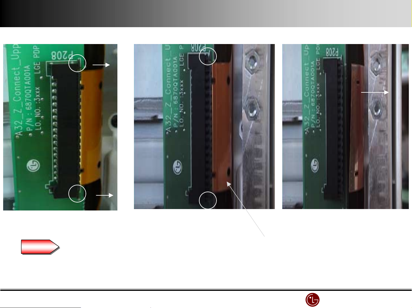
3) Y - Board COF Connector separation
Pull the white LOCK as shown in arrow
Pull the white LOCK as shown in arrow.
Separate COF CONNECTOR by pulling in the left.
Warning
Warning
Be careful to handle LOCK and COF Conne ct or. When LOCK pa rt is damaged, you should replace
a new Y-Board. In case of COF Connector, Module Assembly.
LG Electronics/DND QA
LG Electronics/DND QA Gr
LG Electronics/DND QA LG Electronics/DND QA
Gr
GrGr
Page 50
4) Z - Board COF Connector separation
Separate the fixed Screw of Z-Board.
Pull out Lock as shown in arrow.
Warning
Warning
Be careful not to tear COF Connector.
If COF Connector is torn, replace a new Module Assembly
Condition in Lock part is pulled Pull COF Connector as shown in arrow.
COF Connector
It’s easy to separate COF on condition
that Z-Board Screw is separated.
In case Z-Board is assembled, it’s really
hard to separate.
LG Electronics/DND QA
LG Electronics/DND QA Gr
LG Electronics/DND QA LG Electronics/DND QA
Gr
GrGr
Page 51
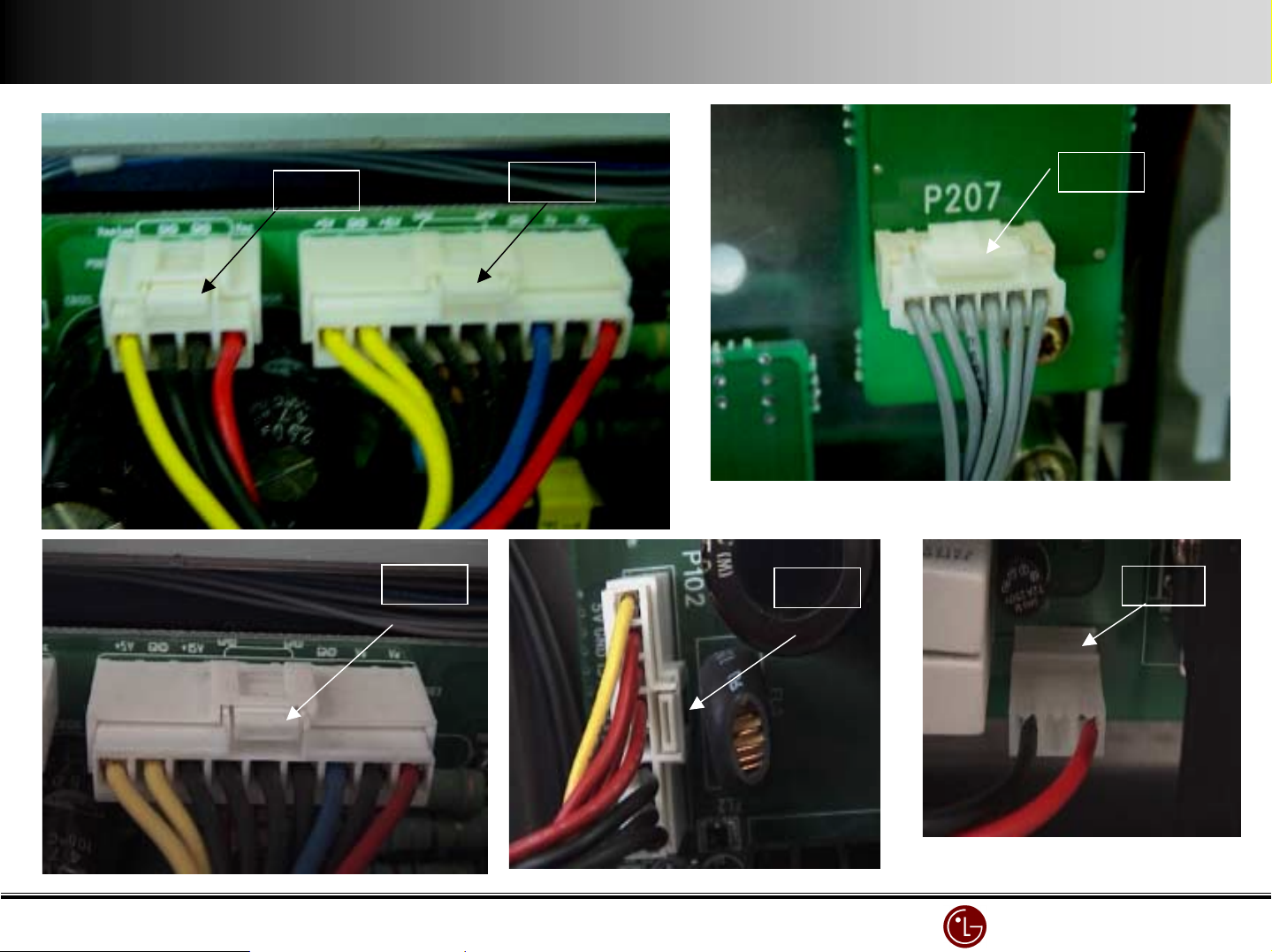
5) Connector separation Guide
Push LOCK and pull o ut
PUSH
PUSH
PUSH
PUSH
PUSH
PULL
LG Electronics/DND QA
LG Electronics/DND QA Gr
LG Electronics/DND QA LG Electronics/DND QA
Gr
GrGr
Page 52
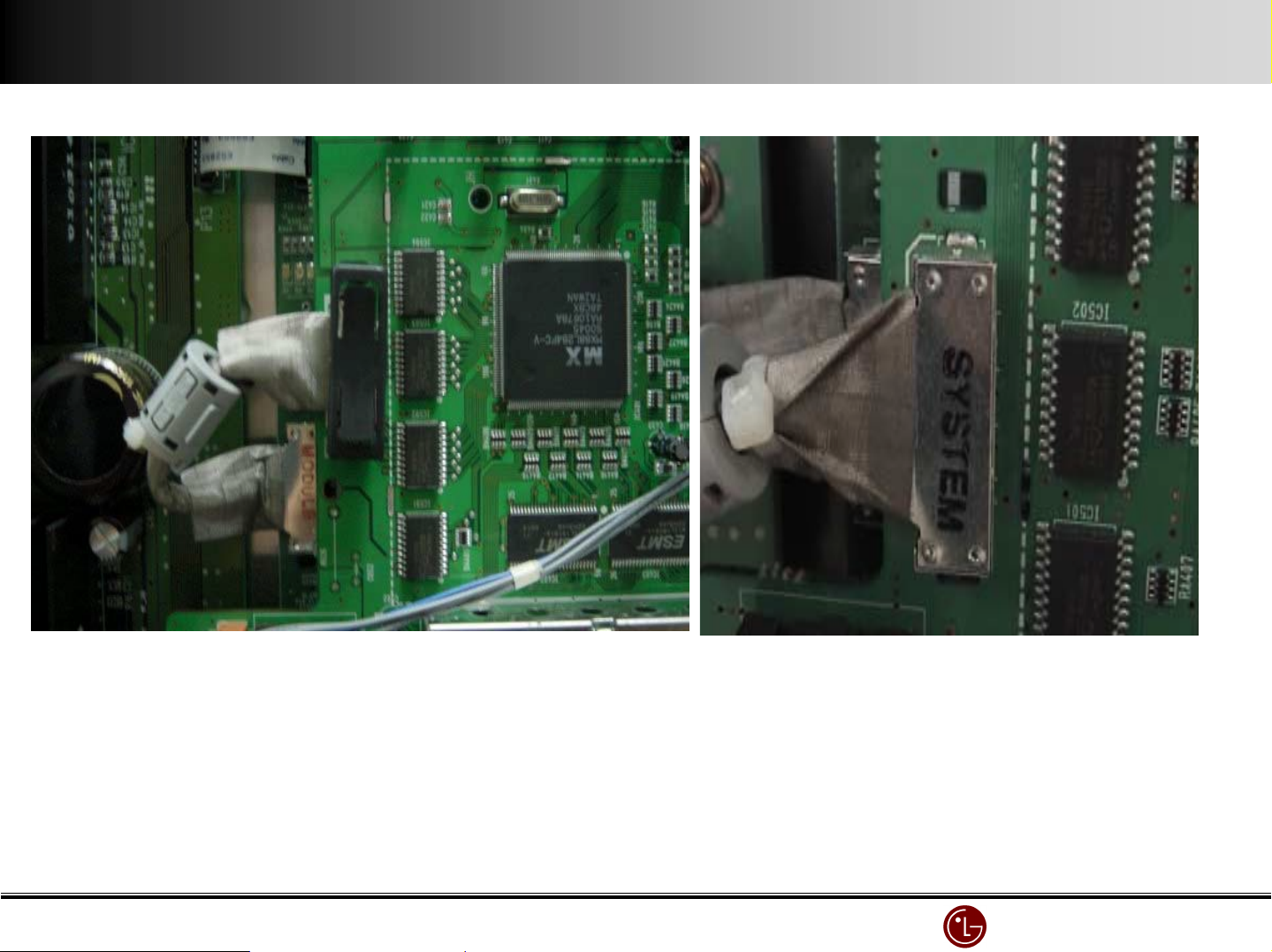
6) Control Board & VSC Board Connector
LG Electronics/DND QA
LG Electronics/DND QA Gr
LG Electronics/DND QA LG Electronics/DND QA
Gr
GrGr
Page 53
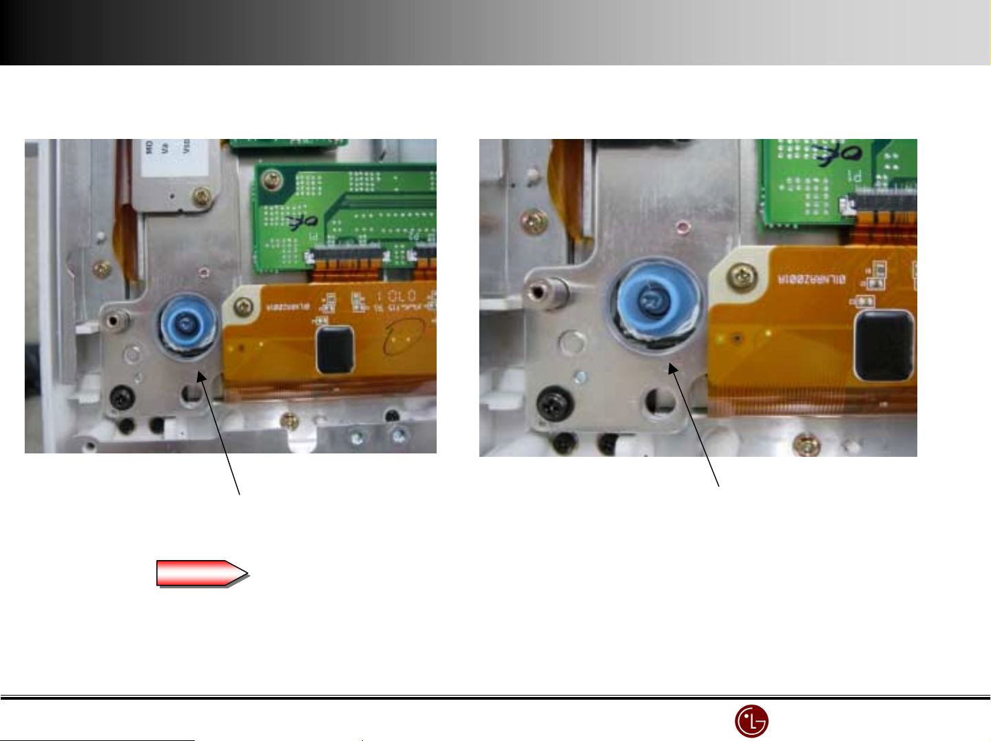
7) Gas injection (Sealing up) condition
Be sealed up after gas injection
Warning
Warning
Be careful to handle the sealed-up part after gas injection.
If it is broken, the gas escapes. So, replace the Module.
Be sealed up after gas injectio n
LG Electronics/DND QA
LG Electronics/DND QA Gr
LG Electronics/DND QA LG Electronics/DND QA
Gr
GrGr
Page 54
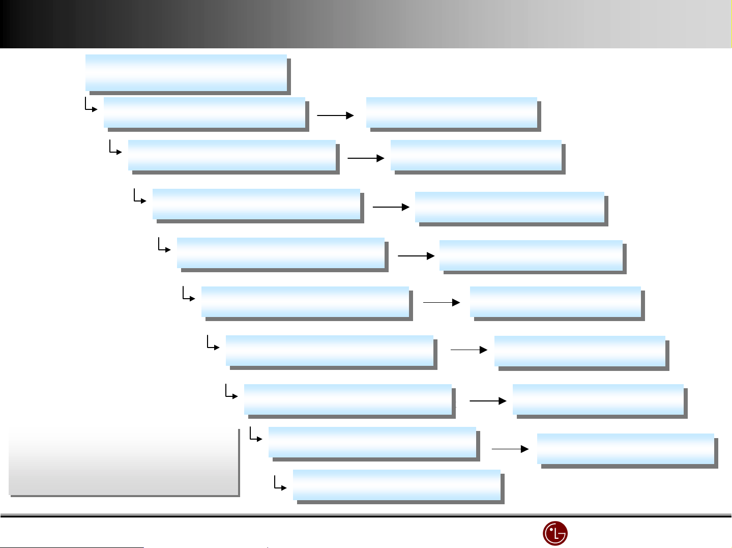
8) Power off in 2 ~ 3 minutes(Protection)
Power is On and off 2~3 minutes.
Power is On and off 2~3 minutes.
(Protection)
(Protection)
P301 Connector Open Check.
P301 Connector Open Check.
P302 Connector Open Check
P302 Connector Open Check
P303 Connector Open Check
P303 Connector Open Check
P304 Connector Open Check
P304 Connector Open Check
P102 Connector Open Check
P102 Connector Open Check
P3, P2 Connector Open Check
P3, P2 Connector Open Check
P005, P003 Connector Open Check
P005, P003 Connector Open Check
OK
X - Board Top Right Change.
X - Board Top Right Change.
OK
X - Board Top Left Change.
X - Board Top Left Change.
OK
X - Board Bottom Right Change.
X - Board Bottom Right Change.
OK
X - Board Bottom Left Change.
X - Board Bottom Left Change.
OK
Z - Board Change.
OK
OK
Z - Board Change.
Y - Board Change.
Y - Board Change.
VSC- Board Change.
VSC- Board Change.
PROTECT operation;
PROTECT operation;
When the load voltage is short.
When the load voltage is short.
When each voltage doesn’t work (in general)
When each voltage doesn’t work (in general)
P006 Connector Open Check
P006 Connector Open Check
Power Board Change
Power Board Change
OK
VSC - Board Change.
VSC - Board Change.
Sound Output IC Short Check
Sound Output IC Short Check
LG Electronics/DND QA
LG Electronics/DND QA Gr
LG Electronics/DND QA LG Electronics/DND QA
Gr
GrGr
Page 55
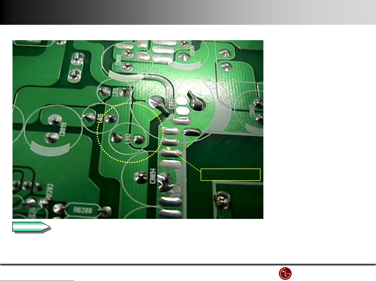
9) Power off in 2 ~ 3 minutes(Protection)
L813 Cold Solder
Symptom : As soon as the power on,
it’s off in 2 - 3minutes.
(PROTECT operation)
Cause : No VS voltage
L813 Coil cold soldering.
Check
Check
Open the Conne ctor connecting to each Board to check the power is off.
if each Board is same, check the Power Board and voltage.
LG Electronics/DND QA
LG Electronics/DND QA Gr
LG Electronics/DND QA LG Electronics/DND QA
Gr
GrGr
Page 56
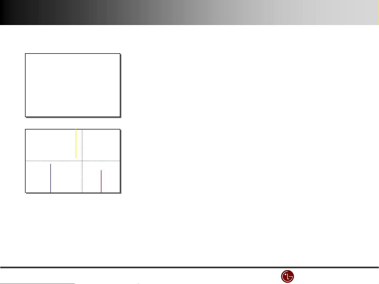
10) ADD BAR inspection and repair
HEATRUN : WHITE
Press the ADJ KEY and check the position of add bar by changing WHITE or
RED or BLUE or GREEN
Top Right Top Left
Bottom Right
Bottom Left
MP-40PA10 uses 4 board such as left,right, top and bottom.
Divide the screen in 4 and once you see ADD BAR check COF CONNECTOR
between MODULE and X-BOARD.
If there is no defect in COF CONNECTOR replace X-BOARD.
But the problem still remains and check the connector between X-BOARD and
CONTROL BOARD. And if you can’t find defect, check CONTROL.
LG Electronics/DND QA
LG Electronics/DND QA Gr
LG Electronics/DND QA LG Electronics/DND QA
Gr
GrGr
Page 57
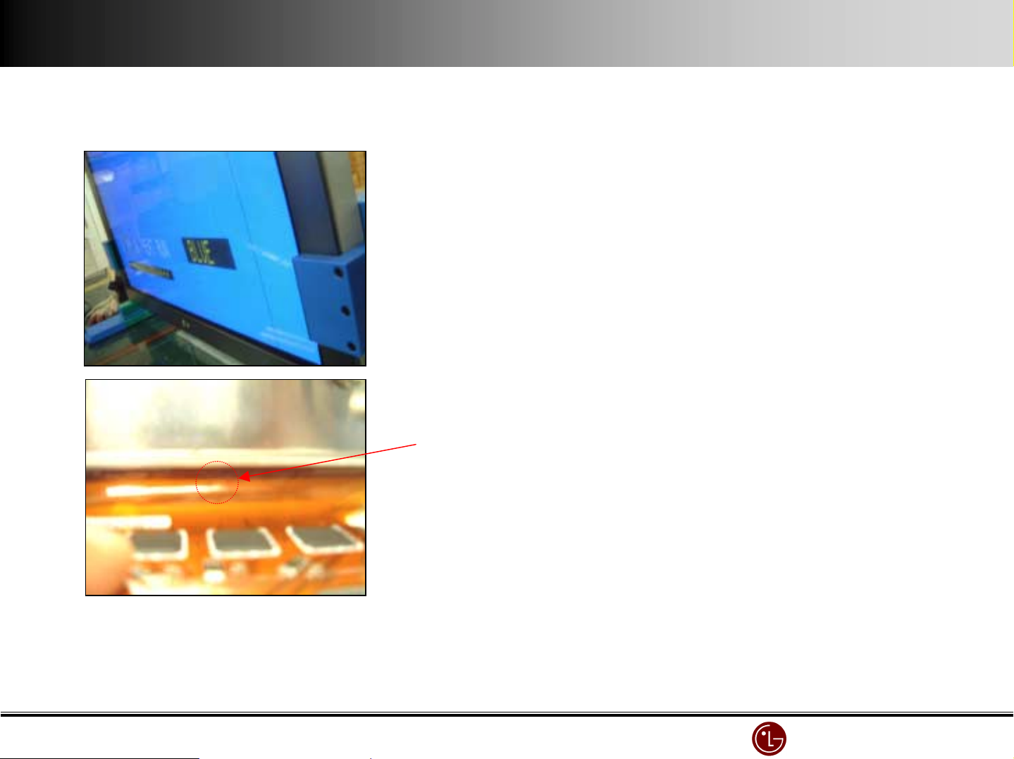
11) One Point Service Guide
Symptom : B color 1 Address line Open
Cause : Dented COF
COF is dented
LG Electronics/DND QA
LG Electronics/DND QA Gr
LG Electronics/DND QA LG Electronics/DND QA
Gr
GrGr
Page 58
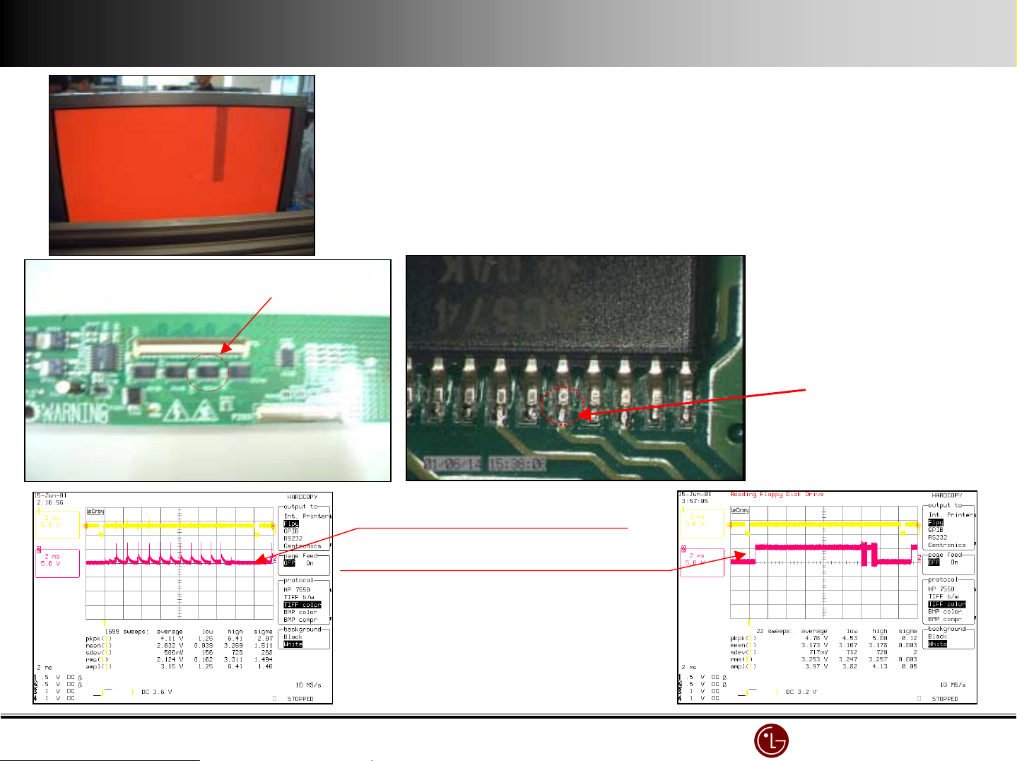
IC14
Symptom : Inferior R Address color
Cause : Inferior DATA output by cold soldering 16 pin of IC14 in X-L-TOP
( Normal waveform after tearing off IC Pin)
Countermeasure : Replace X-L-TOP board.
Cold Soldering
Abnorm al waveform by cold soldering
Normal waveform after tearing off IC pin
LG Electronics/DND QA
LG Electronics/DND QA Gr
LG Electronics/DND QA LG Electronics/DND QA
Gr
GrGr
Page 59
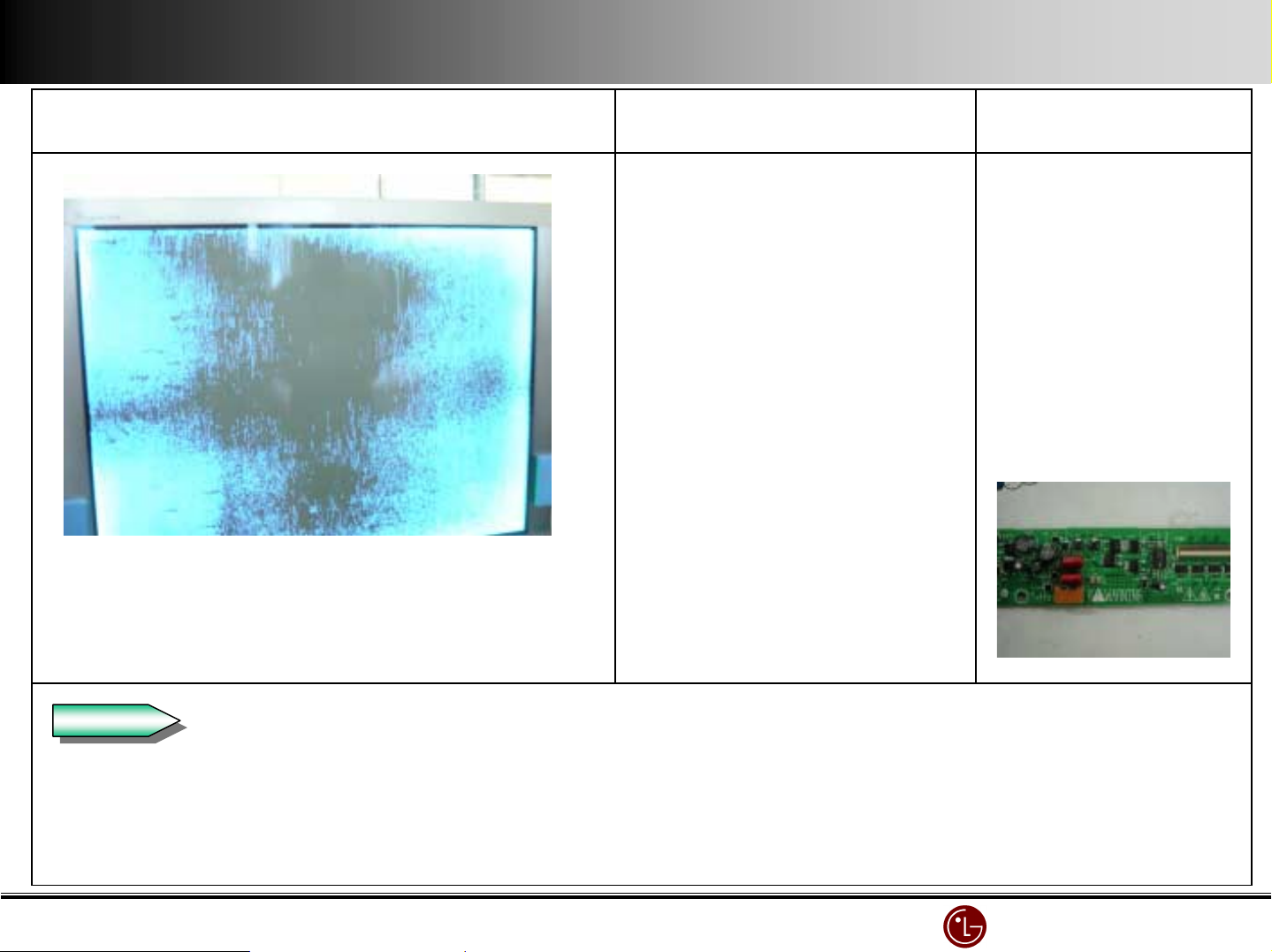
Symptom Causes Countermeasure
The blue spreads on the screen (Mis-discharge)
and power off in 2 ~ 3 seconds.
If you turn on again, it will be same problem.
Check
Check
If 15V line voltage reduces
below 14V,
Mis-discharge occurs and
power off because of
protection circuit.
Replace PSU
(Power Supply Unit)
and defective X-Board.
Defective X-Board
If when Power on, screen shows like above and turn off in 2 seconds, check if turning off or not by disconnecting
all X & Y boards.
LG Electronics/DND QA
LG Electronics/DND QA Gr
LG Electronics/DND QA LG Electronics/DND QA
Gr
GrGr
Page 60
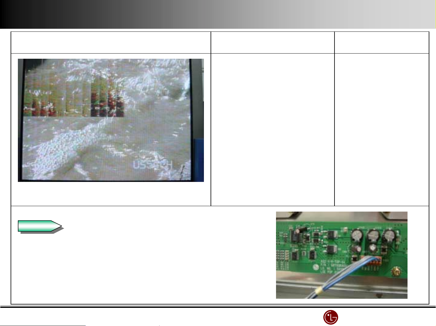
Symptom
Cause
Countermeasure
The top left part of screen is broken
(Top Right X-BOARD)
Check
Check
Check Top right X-BOARD 5V.(If 0V, it happens)
No 5V supply to Top right
X-Board.
Connect 5V line
Check 5V line from SMPS to X-BOARD.
LG Electronics/DND QA
LG Electronics/DND QA Gr
LG Electronics/DND QA LG Electronics/DND QA
Gr
GrGr
Page 61
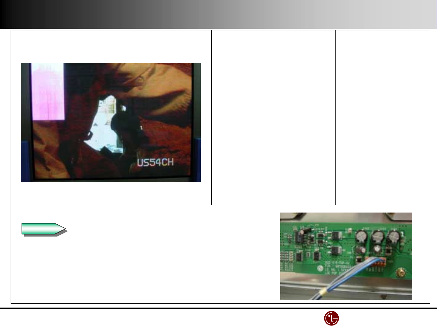
Symptom
Cause
Countermeasure
Pinkish screen in the top left.
(Top right X-BOARD)
Check
Check
Check Top right X-BOARD Va(70V).(If 0V, it happens)
No Va(70V) supply to Top
right X-Board.
Connect 70V line
Check 70V(Va) line from SMPS to X-BOARD.
LG Electronics/DND QA
LG Electronics/DND QA Gr
LG Electronics/DND QA LG Electronics/DND QA
Gr
GrGr
Page 62
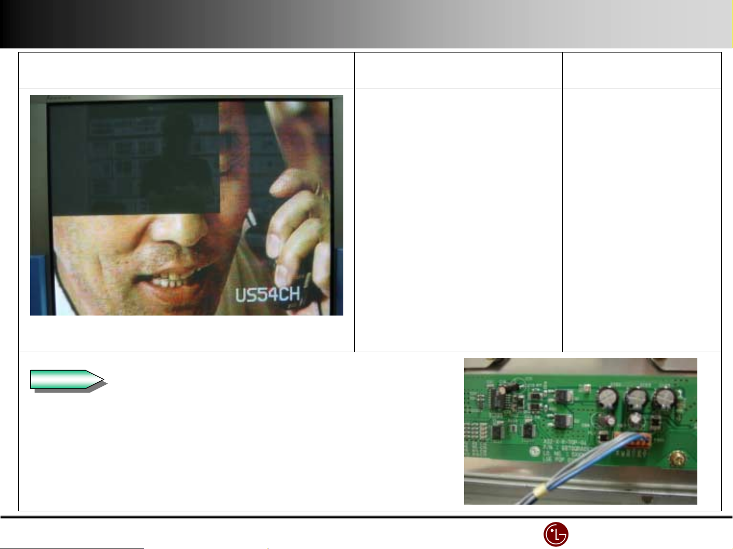
Symptom
Cause
Countermeasure
The 3/5 top left in the screen is blank
(Top Right X-BOARD)
Check
Check
Check Top right X-BOARD 12V.( If 0V, it happens )
No 12V supply to Top right
X-Board.
No Va(70V) supply to Top
right X-Board.
Connect 12V line
Connect 70V line
Check Top right X-BOARD Va(70V).(If 0V, it happens)
Check 12V & 70V(Va) line from SMPS to X-BOARD.
LG Electronics/DND QA
LG Electronics/DND QA Gr
LG Electronics/DND QA LG Electronics/DND QA
Gr
GrGr
Page 63
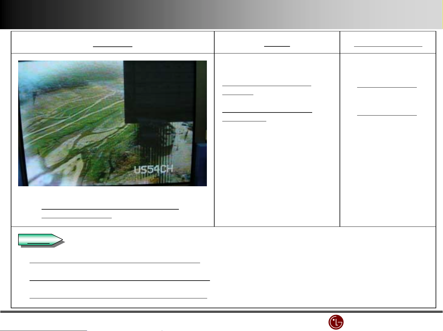
Symptom
Cause
Countermeasure
The 3/5 top right of the screen is blank.
(Top left X-BOARD)
Check
Check
Check Top left X-BOARD 12V.( If 0V, it happens )
No 12V supply to Top left
X-Board.
No Va(70V) supply to Top
left X-Board.
Connect 12V line
Connect 70V line
Check Top left X-BOARD Va(70V).(If 0V, it happens)
Check 12V & Va(70V) line from SMPS to X-BOARD.
LG Electronics/DND QA
LG Electronics/DND QA Gr
LG Electronics/DND QA LG Electronics/DND QA
Gr
GrGr
Page 64
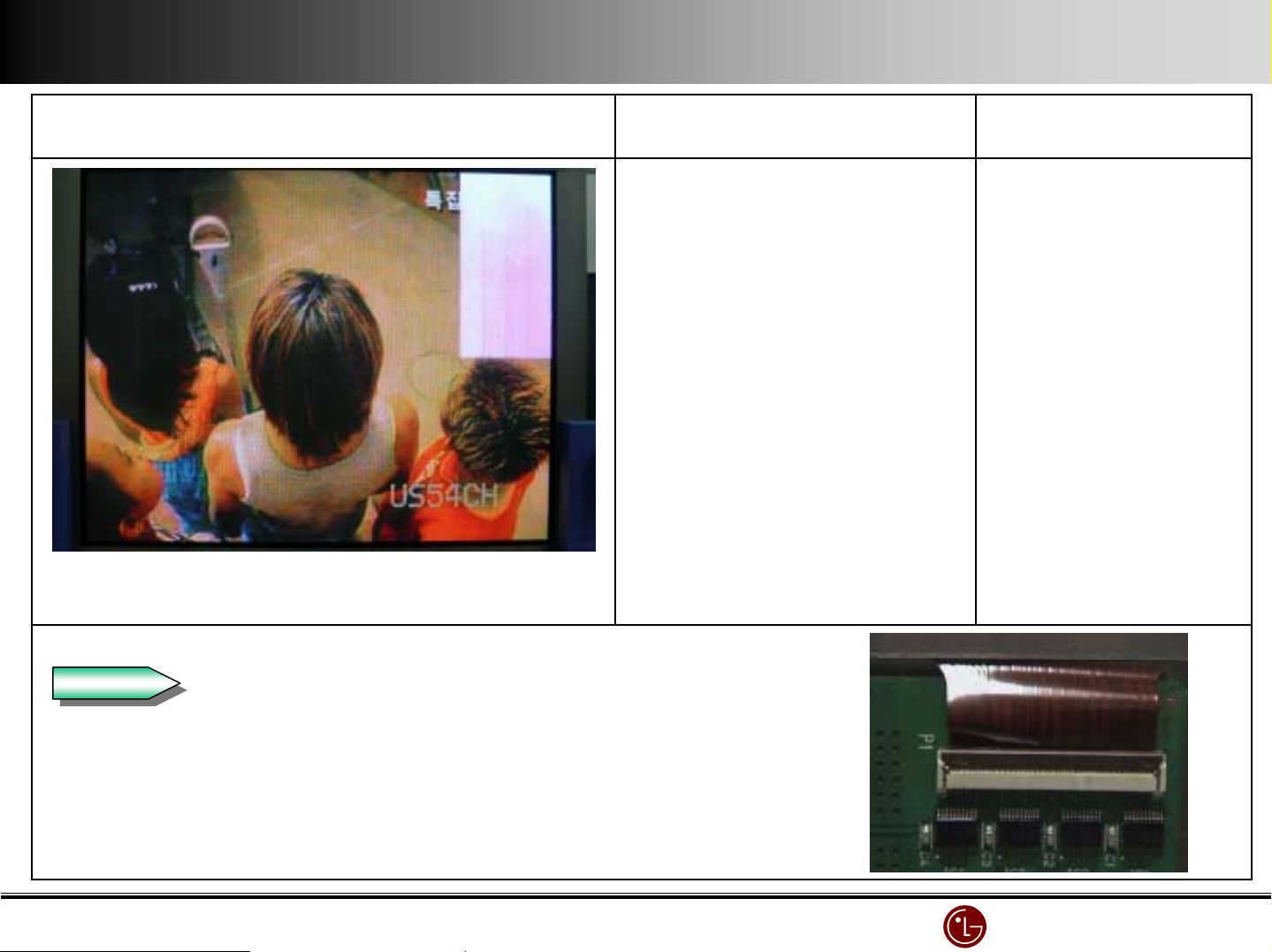
Symptom
Cause
Countermeasure
P1 COF connector on Top left
X-Board is open.
Pinkish screen in the 1/5 top right
(Top left X-BOARD)
Check
Check
Check the contact point and Locking of P1 on Top left X-BOARD.
Reassemble it
LG Electronics/DND QA
LG Electronics/DND QA Gr
LG Electronics/DND QA LG Electronics/DND QA
Gr
GrGr
Page 65
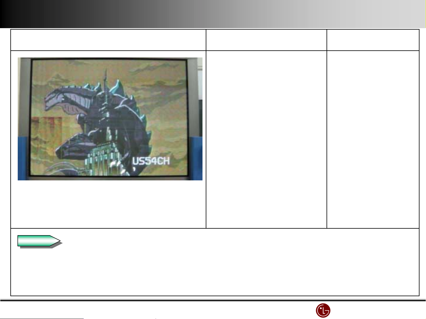
Symptom
Cause
Countermeasure
The 3/5 bottom left of screen is broken.
(BOTTOM RIGHT X-BOARD)
Check
Check
No 5V supply to bottom right
X-Board.
Connect 5V line
Check Bottom right X-BOARD 5V.( If 0V, it happens )
Check 5V line from SMPS to X-BOARD.
LG Electronics/DND QA
LG Electronics/DND QA Gr
LG Electronics/DND QA LG Electronics/DND QA
Gr
GrGr
Page 66
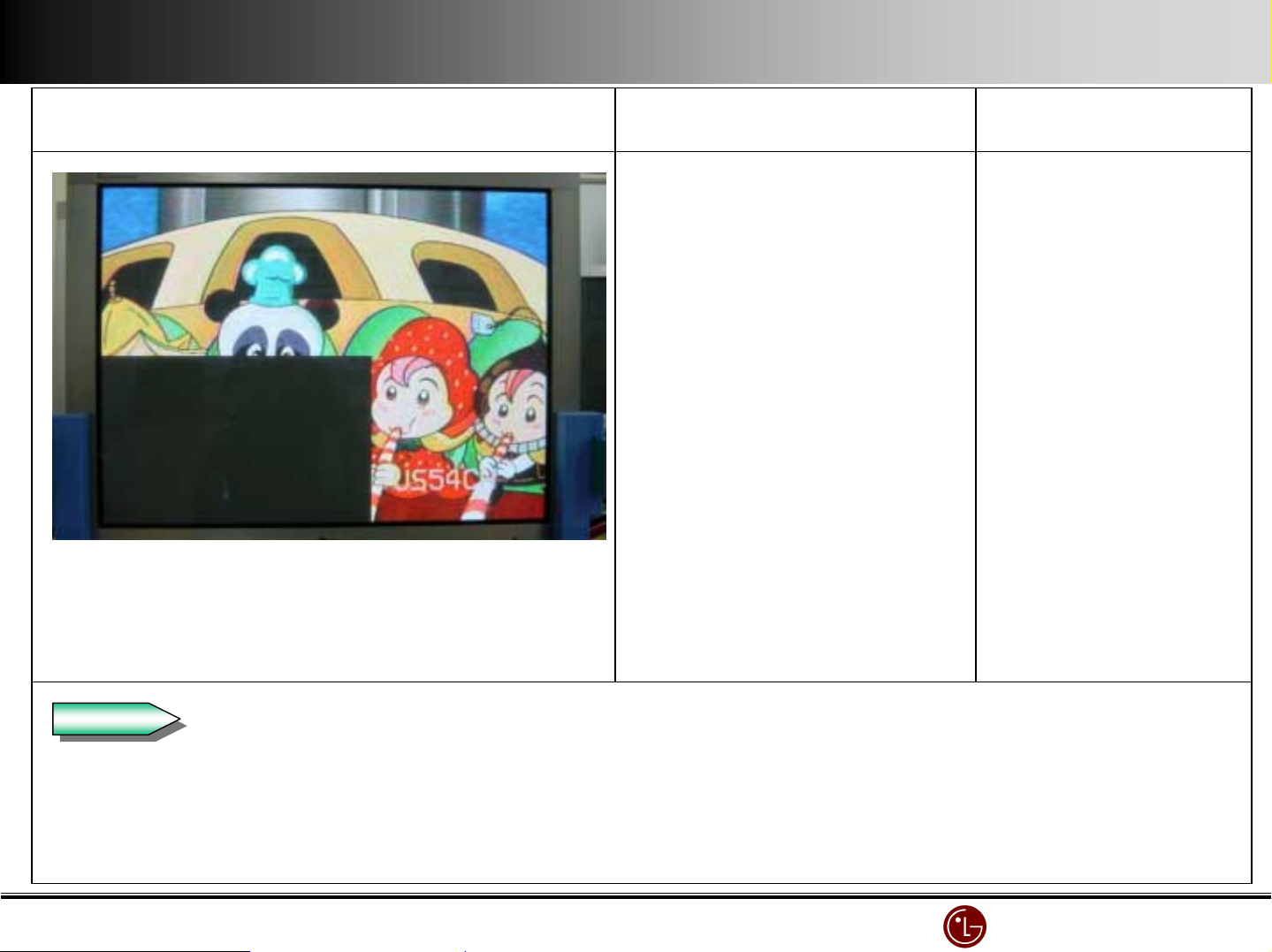
Symptom
Cause
Countermeasure
The 3/5 bottom left of the screen is Blank.
(Bottom Right X-BOARD)
Check
Check
No 12V supply to bottom right
X-Board.
No Va(70V) supply to bottom
right X-Board.
Connect 12V line
Check Bottom right X-BOARD 12V.( If 0V, it happens )
Check 12V line from SMPS to X-BOARD.
LG Electronics/DND QA
LG Electronics/DND QA Gr
LG Electronics/DND QA LG Electronics/DND QA
Gr
GrGr
Page 67
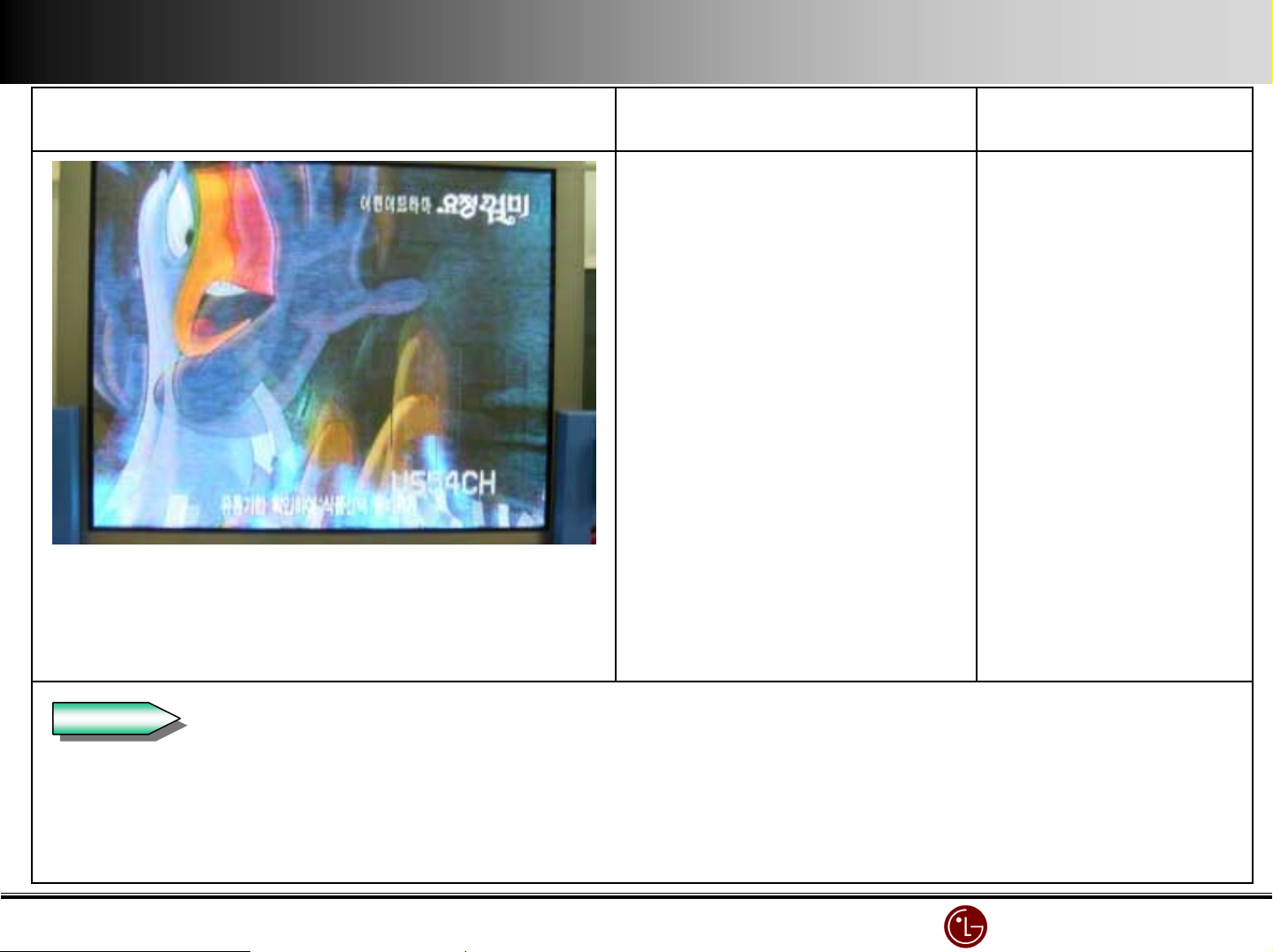
Symptom
Cause
Countermeasure
Check
Check
The 2/5 right of the screen is broken.
(Bottom left X-BOARD)
No 5V supply to bottom left
X-Board.
Connect 5V line
Check Bottom left X-BOARD 5V.( If 0V, it happens )
Check 5V line from SMPS to X-BOARD.
LG Electronics/DND QA
LG Electronics/DND QA Gr
LG Electronics/DND QA LG Electronics/DND QA
Gr
GrGr
Page 68
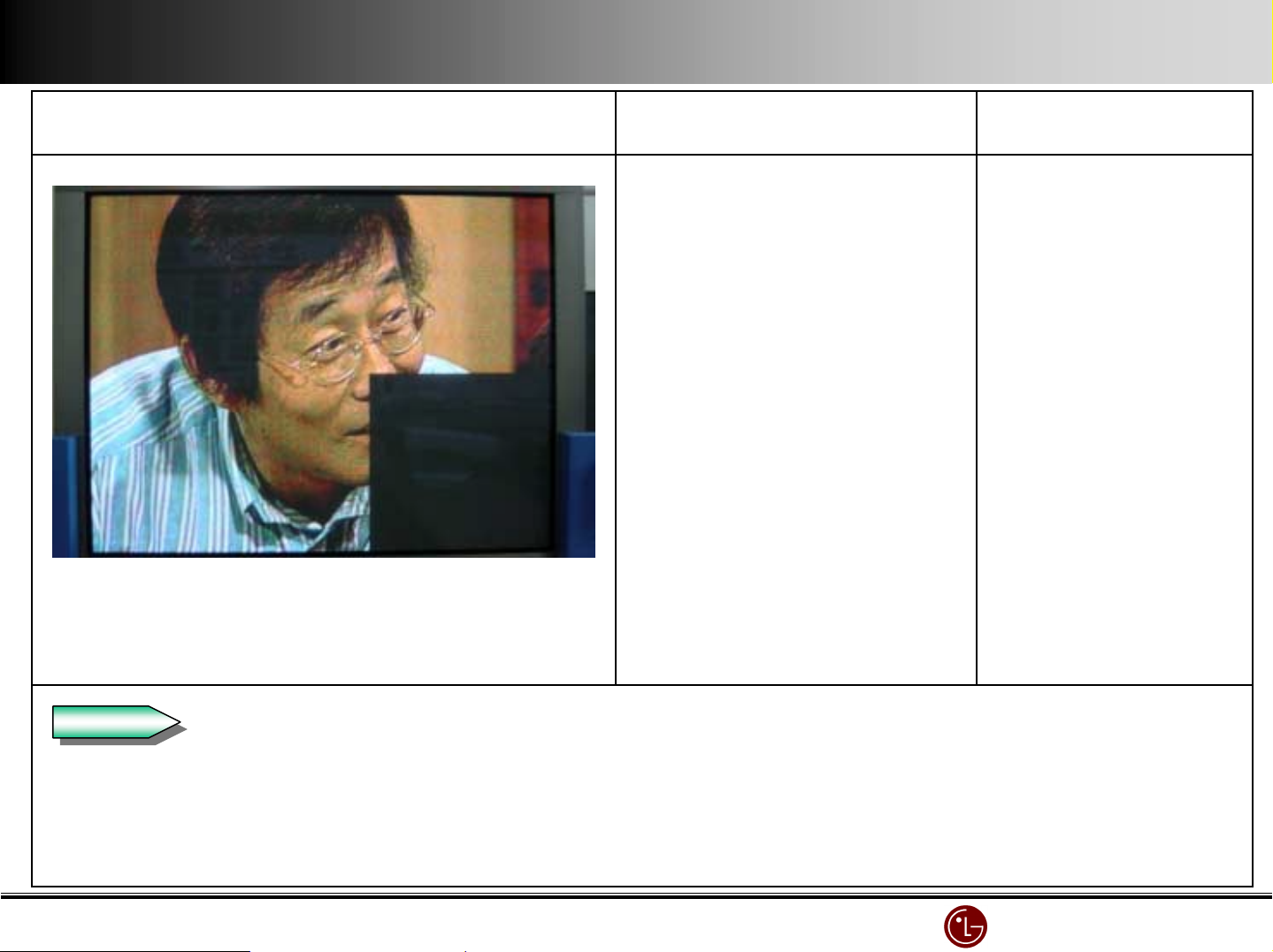
Symptom
Cause
Countermeasure
The 2/5 right part of the screen is blank.
(Bottom left X-BOARD )
Check
Check
No 12V supply to bottom left
X-Board.
Connect 12V line
Check Bottom left X-BOARD 12V.( If 0V, it happens )
Check 12V line from SMPS to X-BOARD.
LG Electronics/DND QA
LG Electronics/DND QA Gr
LG Electronics/DND QA LG Electronics/DND QA
Gr
GrGr
Page 69
Symptom
Cause
Countermeasure
ADDRESS bar appears in the right bottom of the screen.
(X-BOARD BOTTOM LEFT)
Check
Check
Check connecting of the connector of bottom left X-BOARD.
The connecting of X-Board bottom
left connector is bad.
Reassemble it.
Reassemble it.
X-BOARD BOTTOM LEFT CONNECTOR
OPEN.
LG Electronics/DND QA
LG Electronics/DND QA Gr
LG Electronics/DND QA LG Electronics/DND QA
Gr
GrGr
Page 70
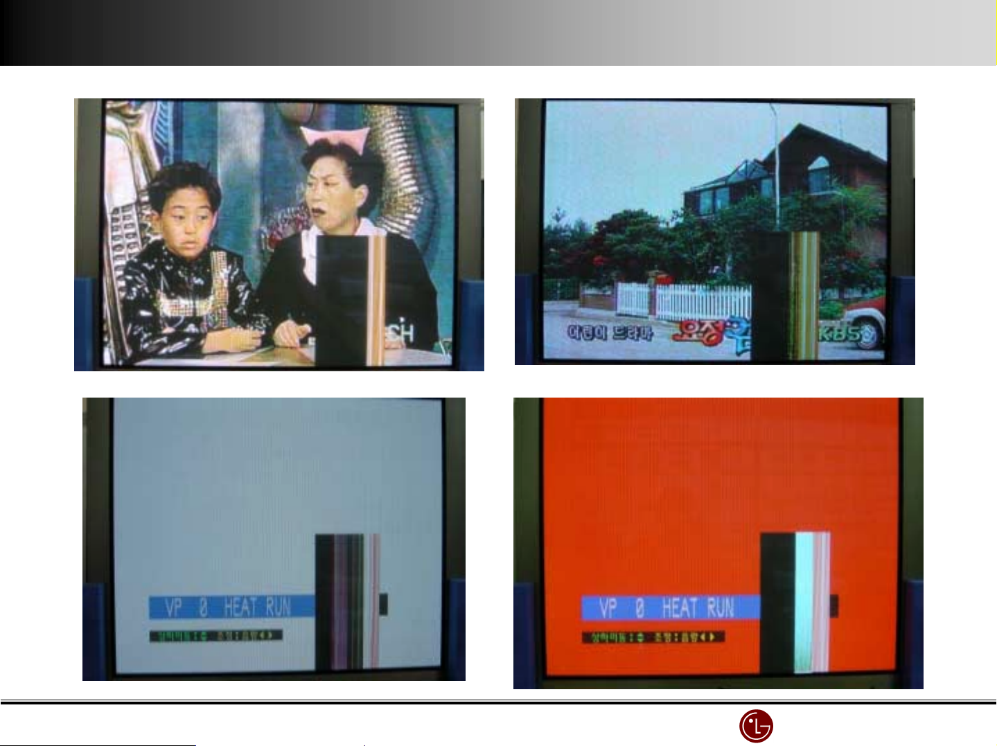
Examples
Examples
ExamplesExamples
LG Electronics/DND QA
LG Electronics/DND QA Gr
LG Electronics/DND QA LG Electronics/DND QA
Gr
GrGr
Page 71
Symptom
Cause
Countermeasure
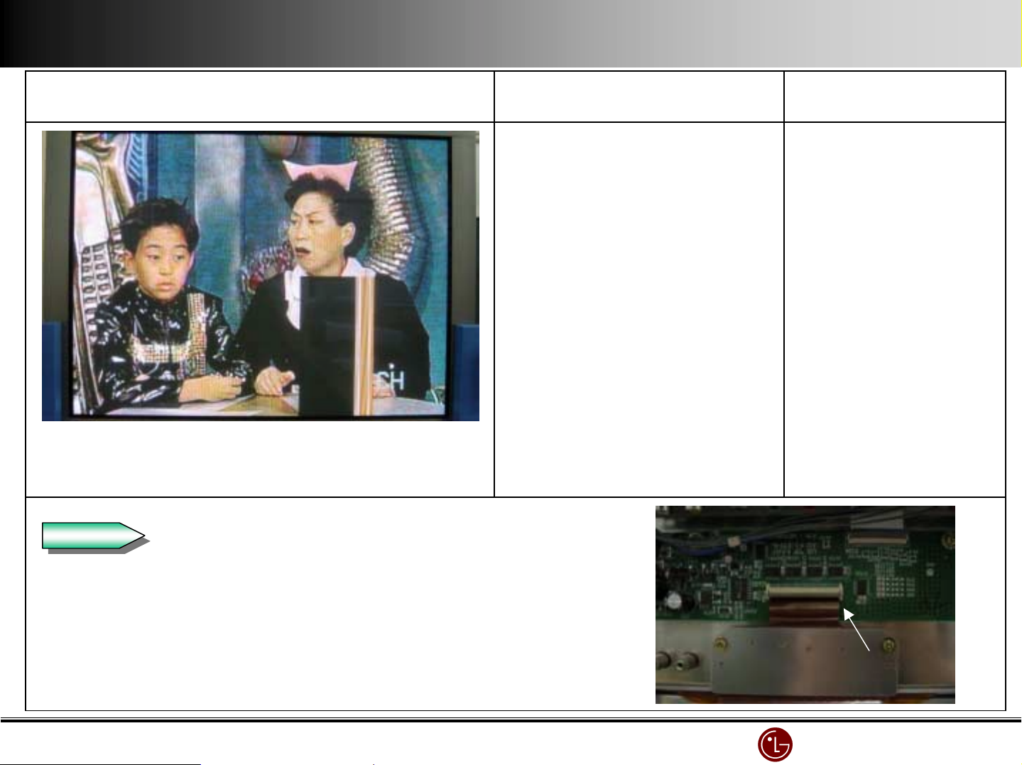
Screen is divided in top and bottom, and vertical bar
appears.
Check
Check
P13 CONNECTOR contact point inferior CHECK.
Connector(P13) is OPEN or
Connecting condition is bad
Reassemble P13.
P13 CONNECTOR SIGNAL CHEK.
P13 CONNECTOR
LG Electronics/DND QA
LG Electronics/DND QA Gr
LG Electronics/DND QA LG Electronics/DND QA
Gr
GrGr
Page 72
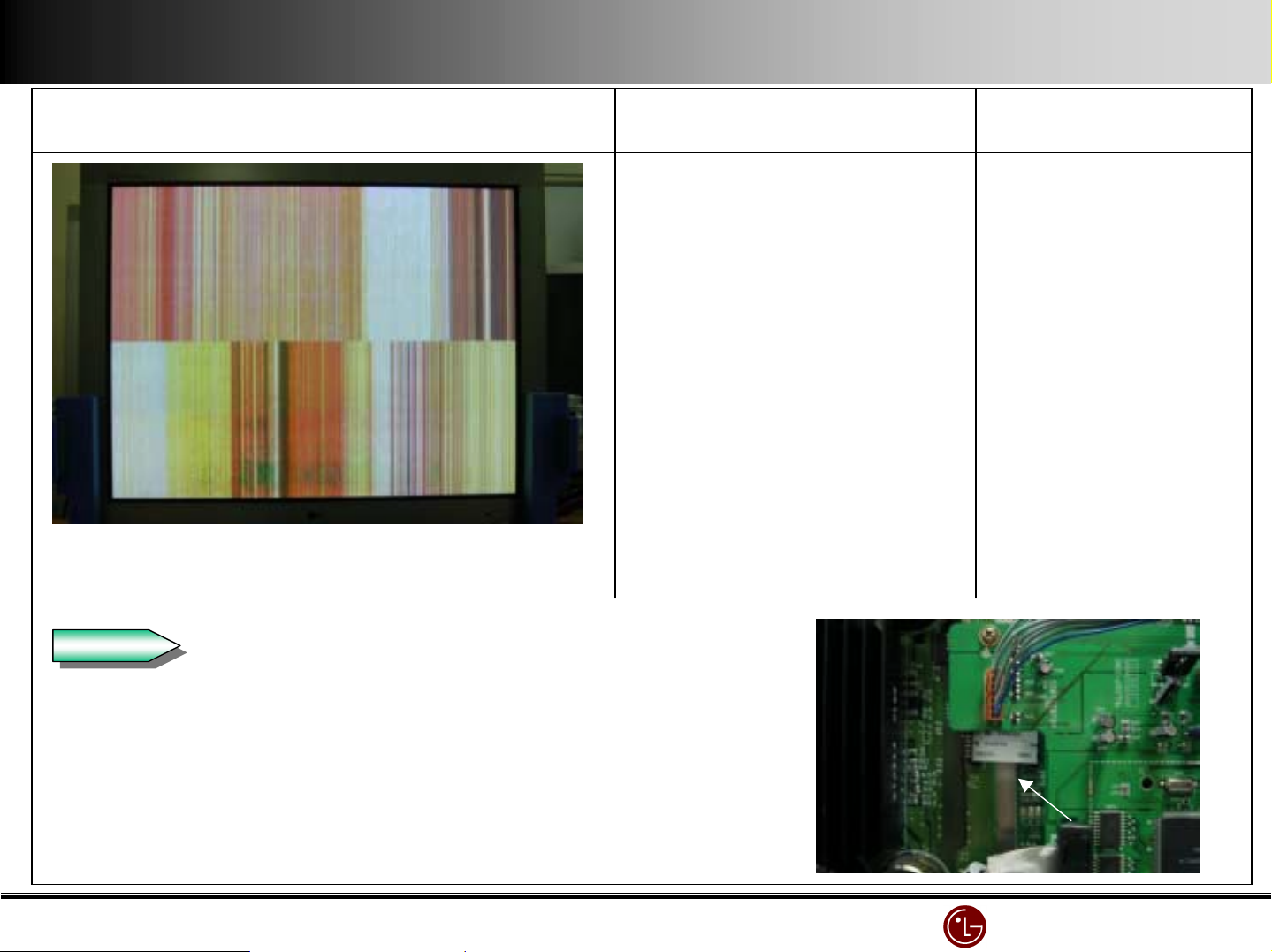
Symptom
Screen is broken and has the vertical/horizontal bar.
Cause
VSC Board Connector is Open. Reassemble VSC Board
Countermeasure
Connector
Check
Check
Check the connector connecting
Reassemble the Connector
LG Electronics/DND QA
LG Electronics/DND QA Gr
LG Electronics/DND QA LG Electronics/DND QA
Gr
GrGr
Page 73
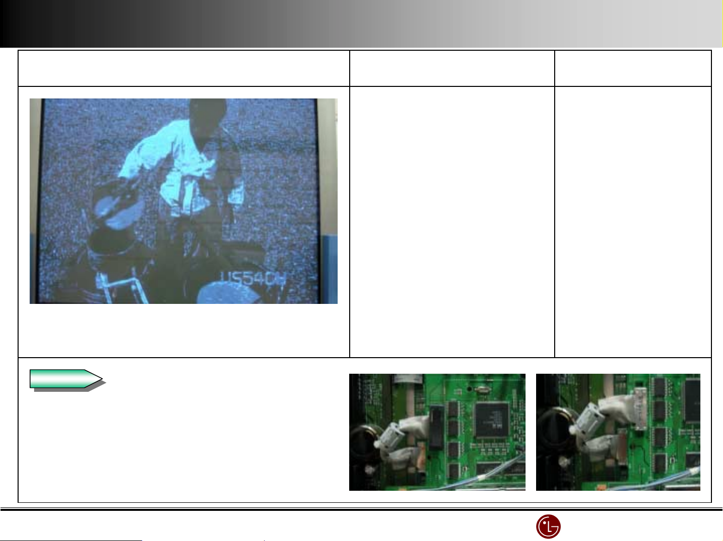
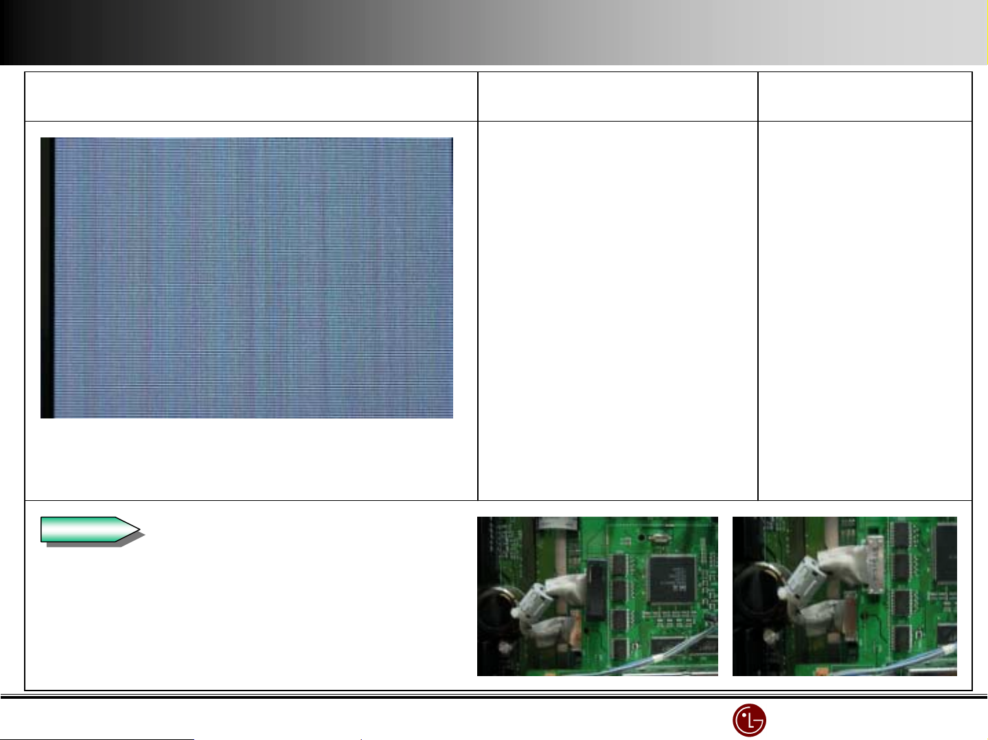
Symptom
The screen is bluish(Mosaic screen)
Cause
Loose VSC Board Connector Reassemble VSC BOARD
Countermeasure
Connector
Check
Check
Check the connection condition of the Connector.
Reassemble the Connector.
LG Electronics/DND QA
LG Electronics/DND QA Gr
LG Electronics/DND QA LG Electronics/DND QA
Gr
GrGr
Page 74
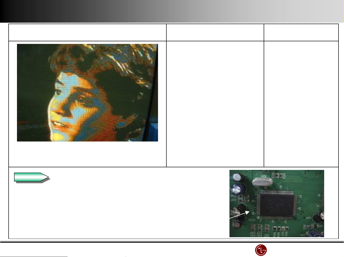
Symptom
The mosaic appears in the screen when it connects to VIDEO Input.
(The sensibility of Y-signal is low.)
When connected to Component Input, it is O.K.
Cause
Bad IC203 Replace IC203(V PC3230D)
Countermeasure
Check
Check
Check if X201 on VSC board oscillates.
Check Video In/Out of IC203 on VSC board.
IC201
(VPC3230D)
Decoder IC
LG Electronics/DND QA
LG Electronics/DND QA Gr
LG Electronics/DND QA LG Electronics/DND QA
Gr
GrGr
Page 75
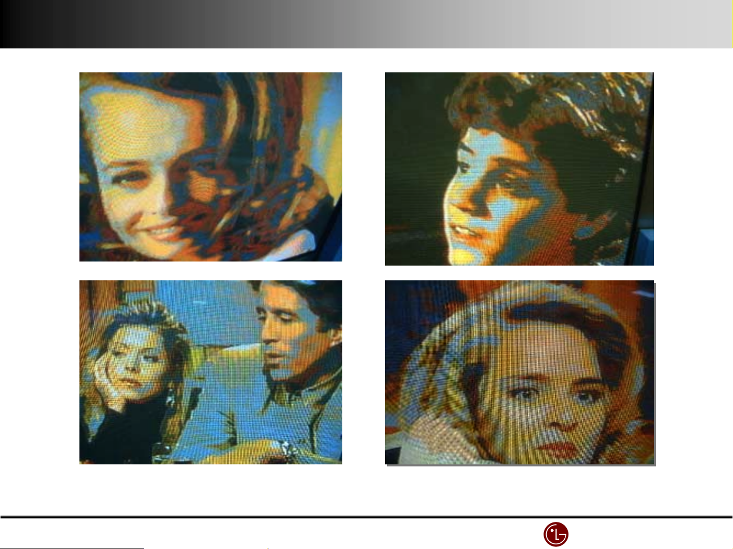
Examples
Examples
ExamplesExamples
IC201(VPC3230D) Decoder is inferior
LG Electronics/DND QA
LG Electronics/DND QA Gr
LG Electronics/DND QA LG Electronics/DND QA
Gr
GrGr
Page 76
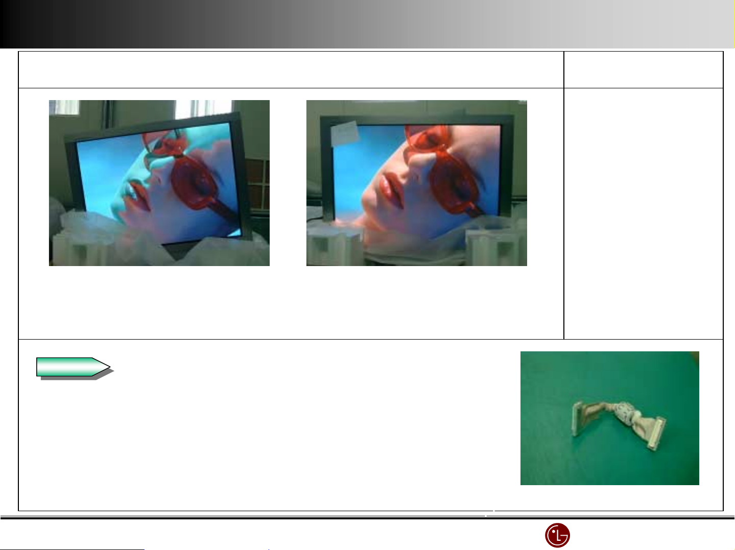
Abnormal Normal
Noise with division of colors
Symptom
Cause
Countermeasure
Bad Connector connecting
Control Board and VSC B/D.
Change the Connect or
Check
Check
Contact point and signal condition of Connector Control Board and VSC Board.
Bad Connector
LG Electronics/DND QA
LG Electronics/DND QA Gr
LG Electronics/DND QA LG Electronics/DND QA
Gr
GrGr
Page 77
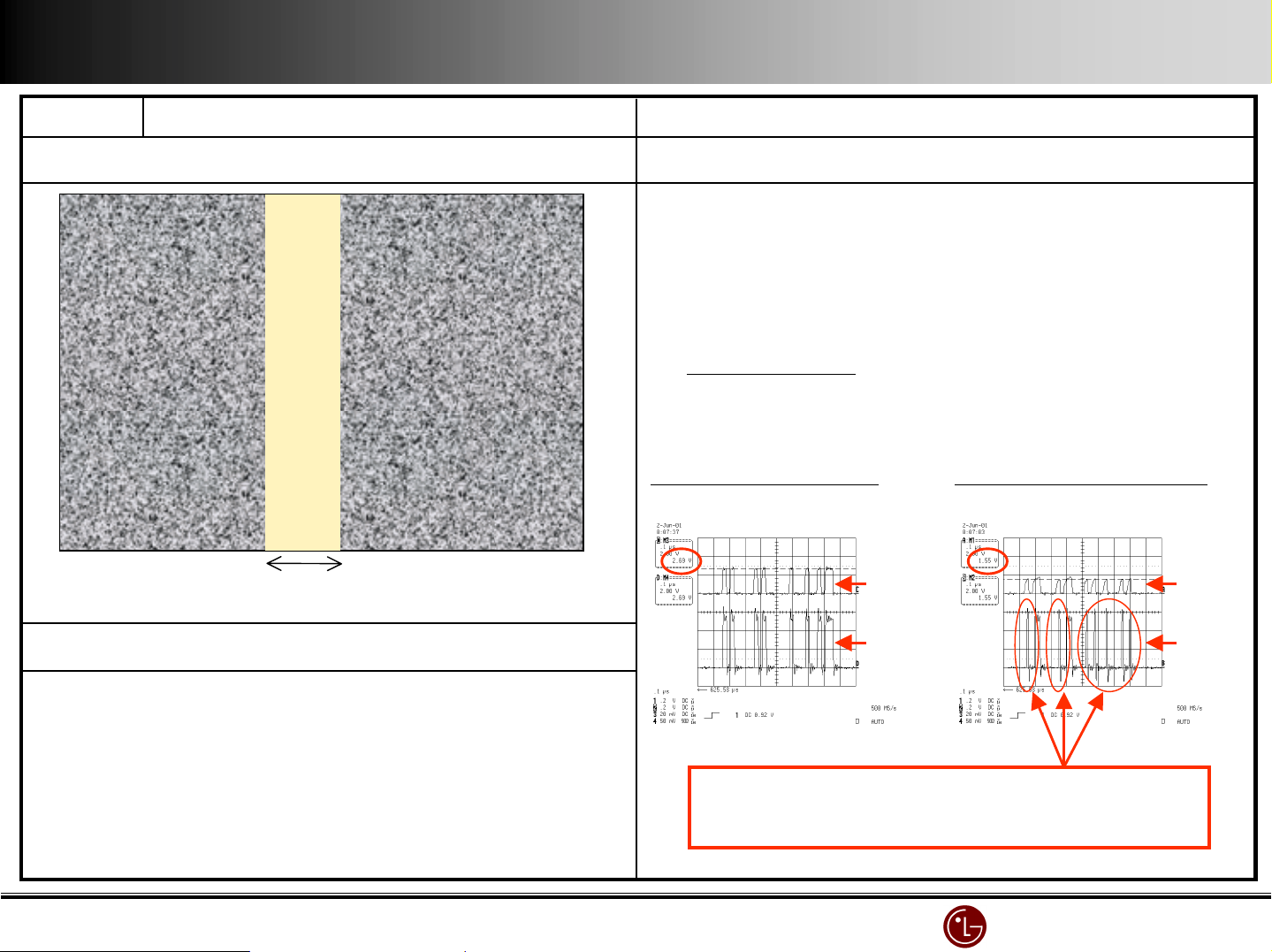
Name No signal Vertical Bar
Symptom Cause and Countermeasure
1.Cause : Bad IC2 (DA1)
F IC2 DA1(Data Arrange) No.162 Pin output is changing
depending on the temperature.G abnormal X-B’d Buffer I C
* Room temperature : 2.5V Output (Normal Pin = over 2.8V)
* Heated : 1.5V Output(Normal Pin = 2.7V )
G
G Bad IC2 (DA1)
GG
2. Countermeasure : Replace IC2
8cm
Realization
When ASIC Chip(IC2 DA1 LGD4001) on Control Board gets
high temperature, you can observe it
(In normal temperatu r e it’s O.K. )
< Waveform of normal pin>
H
H heated
HH
Buffer(74ACT541) waveform abnormally narrows.
I
I In this case, it is impossible for Flip Flop(74AC574) on
II
X B/D to read data.
DA1
Buffer
< Waveform of abnormal pin >
H
H heated
HH
DA1
Buffer
LG Electronics/DND QA
LG Electronics/DND QA Gr
LG Electronics/DND QA LG Electronics/DND QA
Gr
GrGr
Page 78
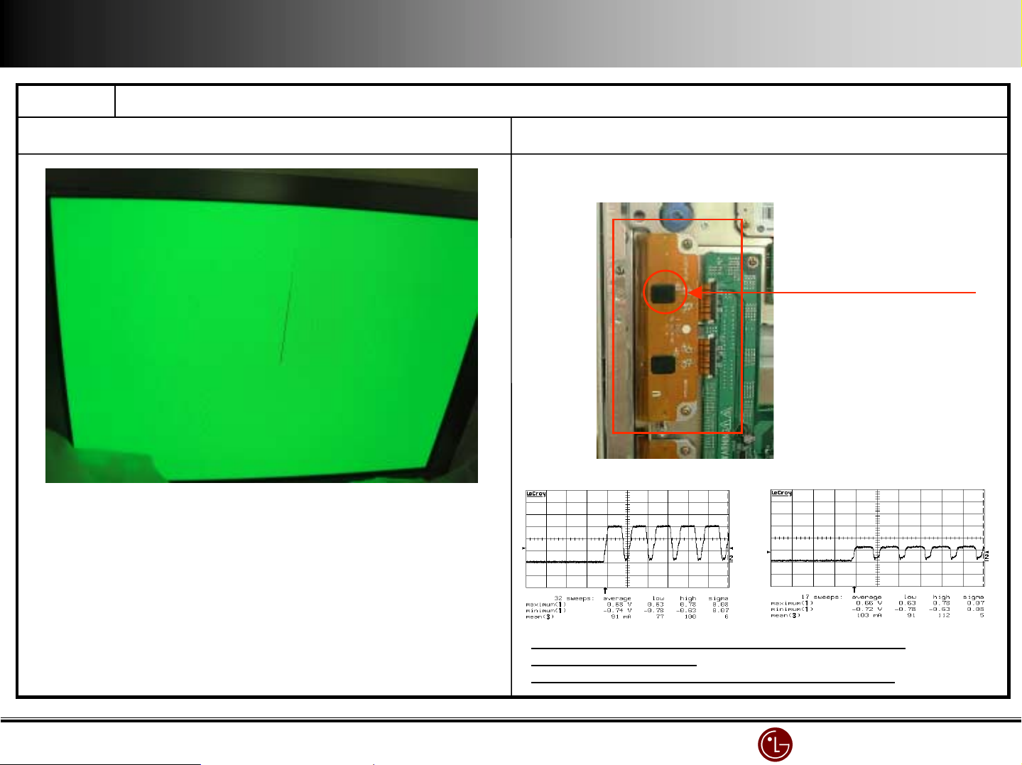
Name Add O pen (Green 1 Line)
Symptom Cause and Countermeasure
1.cause: Add. COF Drive IC inferior
Add. COF Drive IC
Normal Line Data waveform
F the output of inferior line less than that of the normal Line
Add. COF Drive IC inferior
F COF inspectionJKL : 24V Open check (normal 50V)
Open Line Data output waveform
LG Electronics/DND QA
LG Electronics/DND QA Gr
LG Electronics/DND QA LG Electronics/DND QA
Gr
GrGr
Page 79
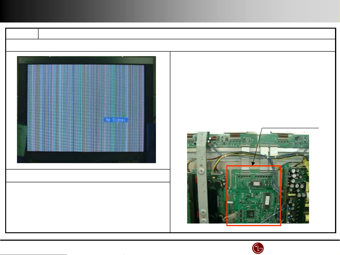
Name Vert ical bar when Power off/on(Mis-discharge)
Symptom Cause and Countermeasure
1.Cause : Control board malfunctions when Power off/on.
2.Countermeasure: Change some parts on Control board.
3.Changing parts : A32_CTRL_03 B/D (Marked on PCB)
-.R14,17,18,21 : 330 ==> 4 .7K (Chip Resistor)
-.R15,16,19,20 : 22K ==> 4. 7K (Chip Resistor)
-.C504, 505 : 0.1uF / 50V add (Chip Capacitor)
Control board
Realization
1.PDP Power on Mode external input
(regardless of wire/wireless signal but it’s easy to reenact in wireless
signal)
2. Remove Power Cord (Power’s off)
3.after about 20minutes, insert Power cord
(automatically the Power’s on and the vertical bar is shown as above)
LG Electronics/DND QA
LG Electronics/DND QA Gr
LG Electronics/DND QA LG Electronics/DND QA
Gr
GrGr
 Loading...